Embed Size (px)
Citation preview
Important User Information Solid state equipment has operational characteristics differingfrom those of electromechanical equipment. “SafetyGuidelines for the Application, Installation and Maintenance ofSolid State Controls” (Allen-Bradley Publication SGI-1.1)describes some important differences between solid stateequipment and hard-wired electromechanical devices.Because of this difference, and also because of the wide varietyof uses for solid state equipment, all persons responsible forapplying this equipment must satisfy themselves that eachintended application of this equipment is acceptable.
In no event will the Allen-Bradley Company or Helm InstrumentCompany be responsible or liable for indirect or consequentialdamages resulting from the use or application of thisequipment.
The examples and diagrams in this manual are included solelyfor illustrative purposes. Because of the many variables andrequirements associated with any particular installation, theAllen-Bradley Company or Helm Instrument Company cannotassume responsibility or liability for actual use based on theexamples and diagrams.
No patent liability is assumed by Allen-Bradley Company orHelm Instrument Company with respect to use of information,circuits, equipment, or software described in this manual.
Reproduction of the contents of this manual, in whole or in part,without written permission of the Allen-Bradley Company andHelm Instrument Company is prohibited.
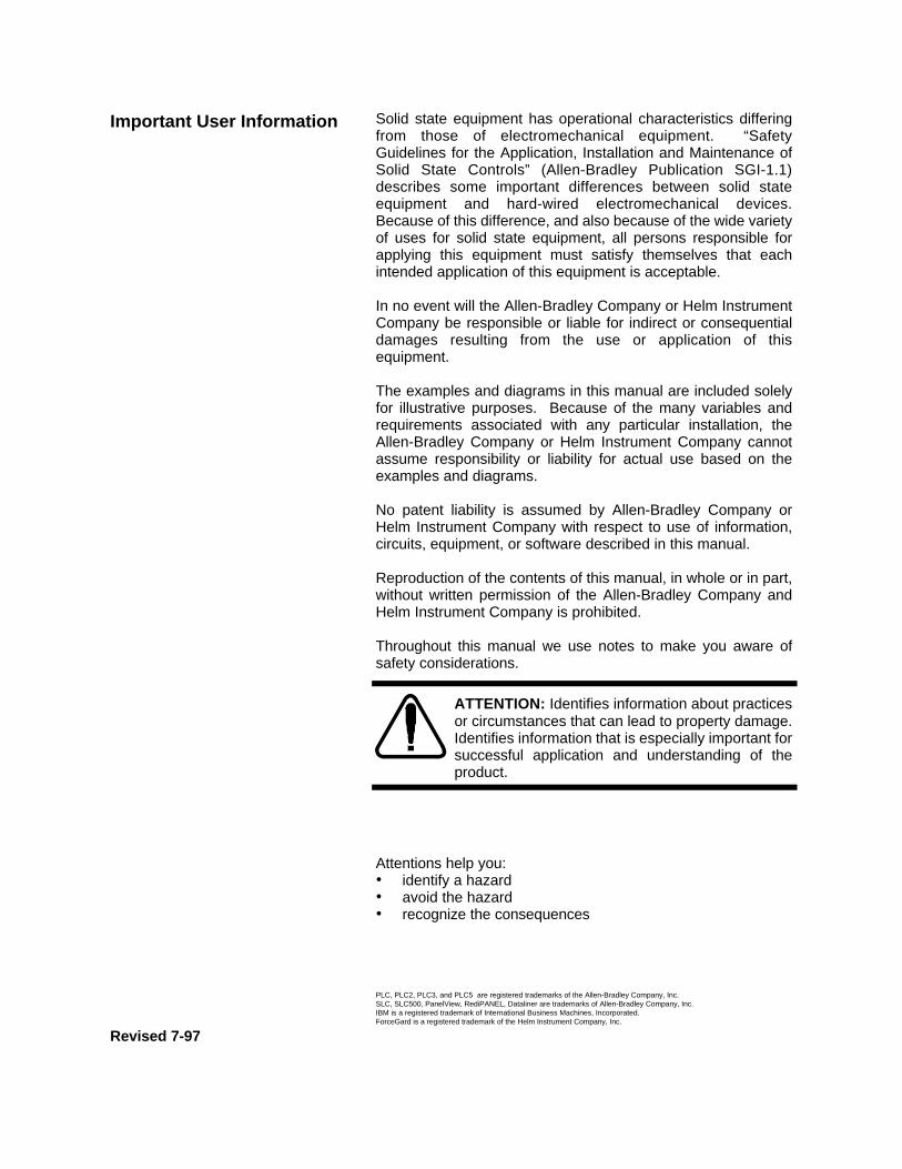
Throughout this manual we use notes to make you aware ofsafety considerations.
ATTENTION: Identifies information about practicesor circumstances that can lead to property damage.Identifies information that is especially important forsuccessful application and understanding of theproduct.
Attentions help you:• identify a hazard• avoid the hazard• recognize the consequences
PLC, PLC2, PLC3, and PLC5 are registered trademarks of the Allen-Bradley Company, Inc.SLC, SLC500, PanelView, RediPANEL, Dataliner are trademarks of Allen-Bradley Company, Inc.IBM is a registered trademark of International Business Machines, Incorporated.ForceGard is a registered trademark of the Helm Instrument Company, Inc.
Revised 7-97

Table of ContentsResolver Input ModuleUser Manual
Preface............................................................................................. P-1
Who Should Use this Manual...........................................................P-1
Purpose of this Manual ....................................................................P-1
Contents of this Manual..............................................................P-2
Related Documentation ..............................................................P-3
Terms and Abbreviations .................................................................P-4
Common Techniques Used in this Manual .......................................P-6
Product Support..........................................................................P-6
Your Questions or Comments on this Manual .............................P-6
Chapter 1..........................................................................................1-1
Module Components........................................................................ 1-1
Resolver Operation .......................................................................... 1-1
Features........................................................................................... 1-1
Hardware Overview ......................................................................... 1-2
Hardware Features .......................................................................... 1-3
Chapter 2..........................................................................................2-1
Getting Started ................................................................................ 2-1
Required Tools and Equipment ....................................................... 2-1
System Operation ............................................................................ 2-2
Resolver Wiring................................................................................ 2-2
Chapter 3..........................................................................................3-1
Channel Configuration, Data and Status.......................................... 3-1
Module Addressing .......................................................................... 3-1
Resolver Module ID Code 3535..................................................... 3-1
Data Table Memory Map ................................................................. 3-1
Output Image ................................................................................ 3-1
Input Image ................................................................................... 3-2
Integer File .................................................................................... 3-3
Overview
GettingStarted
ChannelConfiguration,Data andStatus
Table of ContentsResolver Input ModuleUser Manual
Chapter 4 ........................................................................................ 4-1
Initial Setup Procedures ................................................................... 4-1
Step 1. Set Master/Slave Mode .................................................. 4-1
Step 2. Set Mode Bit to Setup .................................................... 4-2
Step 3. Calibrate Resolver Module for Slave Operation.............. 4-3
Step 4. Set Forward/Reverse Operation Mode........................... 4-4
Step 5. Adjust Resolver Offset.................................................... 4-4
Step 6. Set Mode Bit to Run ....................................................... 4-5
Additional Application Notes........................................................ 4-4
Strokes per Minute (SPM) Calculation ........................................ 4-6
Download Bit............................................................................... 4-7
Chapter 5 ........................................................................................ 5-1
Resolver Wiring Diagram................................................................. 5-1
InitialSetupProcedures
WiringDiagrams

Preface
Read this preface to familiarize yourself with the rest of this manual. This prefacecovers the following topics:
• who should use this manual• the purpose of this manual• terms and abbreviations• conventions used in this manual• Allen-Bradley support
Use this manual if you are responsible for the design, installation, programming, ormaintenance of an automation control system that uses Allen-Bradley small logiccontrollers.
You should have a basic understanding of SLC 500 products. You should understandelectronic process control and be able to interpret the ladder logic instructions requiredto generate the electronic signals that control your application. If you do not, contactyour local Allen-Bradley representative for the proper training before using this product.
This manual is a learning and reference guide for the Helm Resolver Input Module. Itcontains the information you need to install, wire, and use the module.
WhoShould Usethis Manual
Purpose ofthis Manual
P-1
Preface

Preface
Chapter Title Content
Preface Describes the purpose, background,and scope of this manual. Alsospecifies the audience for whom thismanual is intended and defines keyterms and abbreviations usedthroughout this book.
1 Overview Provides a hardware and systemoverview. Explains and illustrates thecomponents of the system.
2 Installation and Wiring Provides installation information andwiring guidelines.
3 Channel Configuration, Data andStatus
Examines the channel configurationand the channel status word, andexplains how the module usesconfiguration data and generates statusduring operation.
4 Ladder Programming Examples Gives an example of the ladder logicrequired to define the module foroperation. Also includes representativeexamples for unique requirements suchas strokes per minute calculation andresolver offset.
5 Wiring Diagrams
A Specifications Provides physical, electrical,environmental, and functionalspecifications for the module.
B Ladder Program
Contents ofthis Manual
P-2

Preface
For Read this Document DocumentNumber
An overview for the SLC 500 family ofproducts
SLC 500 System Overview 1747-2.30
A description on how to install and use yourModular SLC 500 programmable controller
Installation & Operation Manual for ModularHardware Style Programmable Controllers
1747NI002
A description on how to install and use yourFixed SLC 500 programmable controller
Installation & Operation Manual for FixedHardware Style Programmable Controllers
1747-NI001
A procedural manual for technicalpersonnel who use APS to develop controlapplications
Allen-Bradley Advanced ProgrammingSoftware (APS) User’s Manual
1747-NM002
A reference manual that contains status filedate, instruction set, and troubleshootinginformation about APS
Allen-Bradley Advanced ProgrammingSoftware (APS) Reference Manual
1747-NR001
An introduction to APS for first-time users,containing basic concepts but focusing onsimple tasks and exercises, and allowingthe reader to begin programming in theshortest time possible
Getting Started Guide for APS 1747-NM001
A procedural and reference manual fortechnical personnel who use an HHT todevelop control applications
Allen-Bradley Hand-Held Terminal User’sManual
1747-NP002
An introduction to HHT for first-time users,containing basic concepts but focusing onsimple tasks and exercises, and allowingthe reader to begin programming in theshortest time possible
Getting Started Guide for HHT 1747-NM009
A resource manual and user’s guidecontaining information about the analogmodules used in your SLC 500 system
SLC 500 Analog I/O Modules User’sManual
1746-NM003
A complete listing of current AutomationGroup documentation, including orderinginstructions. Also indicates whether thedocuments are available on CD-ROM or inmulti-languages
Automation Group Publication Index SD499
A glossary of industrial automation termsand abbreviations
Allen-Bradley Industrial AutomationGlossary
ICCG-7.1
An article on wire sizes and types forgrounding electrical equipment
National Electrical Code Published by theNational FireProtectionAssociation ofBoston, MA.
Related Documentation
The following documents contain information that may be helpful to you as youuse Allen-Bradley SLC products. To obtain a copy of any of the Allen-Bradleydocuments listed, contact your local Allen-Bradley office or distributor.
P-3

Preface
The following terms and abbreviations are used throughout this manual. For definitionsof terms not listed here refer to Allen-Bradley’s Industrial Automation Glossary,Publication ICCG-7.1.
Calibration - Procedure, performed by trained personnel, to set the RMS (mean squareroot) voltages of the resolver.
Chassis - A hardware assembly that houses devices such as I/O modules, adaptermodules, processor modules, and power supplies.
Configuration Word - Contains the configuration information needed by the module toconfigure and operate. Information is written to the configuration word through the logicsupplied in your ladder program.
Data Word - A 16-bit integer that represents the value of the analog input channel. Thechannel data word is valid only when the channel is enabled.
LSB - (Least Significant Bit) Refers to a data increment defined as the full scale rangedivided by the resolution. The bit that represents the smallest value within a string ofbits.
Master/Slave Operation - Selectable mode of module operation. Default is Masterwhen module is wired to a Helm Model HR1101 resolver. Mode is Slave when modulereceives input by tapping off of an existing resolver. Slave mode requires a calibrationprocedure.
Monitor Mode - Normal run state.
Multiplexer - A switching system that allows several input signals to share a commonA/D converter.
Offset - A value represented in degrees to restore resolver to zero at the top of thestroke. Required when resolver has not been mechanically set to zero.
Remote Configuration - A control system where the chassis can be located severalthousand feet from the processor chassis. Chassis communication is via the 1747-SNScanner and 1747-ASB Remote I/O Adapter.
Resolution - The smallest detectable change in a measurement, typically expressed inengineering units (e.g. 0.15C) or as a number of bits. For example a 12-bit system has4,096 possible output states. It can therefore measure 1 part in 4096.
Resolver - Sometimes called encoder. Device attached on a machine to determinemachine stroke position. Sine/cosine based resolver required for Helm Resolver InputModule.
Sampling time - The time required by the A/D converter to sample an input channel.
Terms andAbbrevia-tions
P-4

Preface
Scale - Value used to describe the press/machine overall tonnage. Set for maximumvalue of one channel. For example, settings for a 150 ton press = 75.
Setup Mode - Status condition of module. Normally enabled to perform calibration andsetup procedures.
Status Word - Contains status information about the channel’s current configurationand operational state. You can use this information in your ladder program to determinewhether the channel data word is valid.
Strokes per Minute (SPM) - Value calculated when a machine cycles through acomplete rotation ( 0 to 360 degrees)..TSM - Acronym for Through-the-Stroke load monitoring. Resolver input is required formonitoring the load being developed during machine cycle.
Update Time - The time required for the module to sample and convert the input signalsof all enabled input channels and make the resulting data values available to the SLCprocessor.
Terms andAbbrevia-tions(continued)
P-5

Preface
The following conventions are used throughout this manual:
• Bulleted lists such as this one provide information, not procedural steps.• Numbered lists provide sequential steps or hierarchical information.
Contact your Helm representative or call Helm direct at 419/893-4356:
• sales and order support• product technical training• warranty support• support service agreements
Your Questions or Comments on this Manual
If you have any suggestions for how this manual could be made more useful to you,please send us your ideas.
CommonTechniquesUsed in thisManual
ProductSupport
P-6

Appendix AElectricalSpecifications:
Backplane Current Consumption 49m@5VDC57m@24VDC
Backplane Power Consumption 2W
Number of Channels 1
I/O Chassis Location Any I/O module slot except 0
Calibration Manual Calibration
Isolation 500 VDC continuous between inputs andchassis ground, and between inputs andbackplane
PhysicalSpecifications:
LED Indicators 1 Power Indicator1 Communications Indicator
Module ID Code 3535
Recommended Cable Resolver Cable #27081
Terminal Strip 8-pin removable
EnvironmentalSpecifications:
Operating Temperature 0°C to 60°C (32°F to 140°F)
Hazardous Environment Classification Class 1 Division 2 Hazardous Environment
InputSpecifications:
Type of Input Resolver
Display Resolution 0.1º
Overall Module Accuracy /- 8+ 1 LSB arc mins.
Module Update Time 200µsec
Page A-1

Chapter 1
You have just purchased the most advanced Programmable Limit Switch/Die Monitoringsolution available. HELM INSTRUMENT COMPANY, INC. manufactures a completeline of monitoring control solutions for use on metal stamping, forging, compaction andassembly presses; cold forming, cold heating, injection molding and die cast machines.
Resolvers, standard or custom transducers and load cells are available for in-diemonitoring of transfer or progressive tooling.
At HELM, quality is inherent not only in the design of our products but in the attitudes ofour employees as well. We’re working together to give you the best. After all, that’swhat our business is all about - providing innovative instrumentation to help make yourmanufacturing process more productive and your operation more effective.
The Helm Resolver Input module provides intelligent absolute position feedback to theAllen-Bradley SLC family of programmable controllers. The module supplies A-Bprocessors position and velocity data from ultra-reliable resolver based transducers.Each HM571-RES module occupies a single slot in the I/O rack. Position data isupdated every 200 micro seconds. Up to 16 user programmable on/off states enableprogrammable limit switching to enhance control solutions.
Features include: velocity data acquired at up to 2000 RPM, programmable positionresolution up to 4096 counts per turn and a programmable resolver offset value.
When used with the Helm ForceGard strain gage input module, the resolver moduleprovides for real time signature analysis.
The Helm Resolver module resides on the backplane of the Allen-Bradley 1746SLC-5/03. The system is comprised of two parts; the input module and a sine/cosinebased resolver such as the Helm Model HR-1101 resolver. The HR-1101 sine/co-sineResolver is housed in a rugged enclosure designed especially for industrial applications.The resolver is a very accurate absolute position shaft encoder known for it’s extremedurability. Helm resolvers are passive devices which consist of brushless rotarytransformers with one rotor and two stator windings. These windings are positioned at90 degrees apart from one another thus providing a sine and cosine analog output signalcorresponding to the shaft position.
Components
Page 1-1
Overview

The resolver module fits into any single-slot, except the processor slot(0). It is a Class1 module (uses eight input words and eight output words).
The Helm Resolver input module can accept input from one resolver. Multiple HelmHR-1101 resolvers can be wired in paralleled to one resolver input module.
The module has no output channels. Module configuration requires manual and userprogrammable setup.
The resolver module receives and stores digitally converted analog data into its imagetable for retrieval by modular SLC 500 processors.
Page 1-2
Chapter 1
HardwareOverview

Chapter 1
Page 1-3
Power LED Indicates 5 volts is supplied.
Transmit LED Indicates module is communicating toprocessor.
Door Label Resolver wiring diagram
Transmit Connector Connector for communication with HelmForceGard module via Receive IN jack.
8-Pin Connector For resolver input wiring.
Dip Switches S1- Adjustment for Master/Slave operation.S2- Adjustment for Forward/Reverse resolverrotation.
Potentiometers Three of the four pots are used for calibratingthe resolver, a sine adjust, a cosine adjust anda reference adjust for slave operation.
Voltage Test Points Used with voltage meter when adjusting sine/cosine potentiometers.
HardwareFeatures
TRANSMIT
POWER
ANALOG
HELM INSTRUMENTCO., INC.
MAUMEE, OHIO USA
TRANSMIT
HELMINSTR
UMENT
COM
ADEIN
USA
J1R15
S2
REF
SIN
(FORWARD)
(REVERSE)
J6
J4CO
S
(SLAVE)
(MASTER)J3
REF
R24 R22(SIN)
R25(COS)
R23(REF)
S1

Chapter 2This chapter can help you to get started using the Helm Resolver input module. Theprocedures included here assume that you have a basic understanding of SLC 500products. You should understand electronic process control and be able to interpret theladder logic instructions required to generate the electronic signals that control yourapplication.
Because it is a start-up guide, this chapter does not contain detailed explanations aboutthe procedures listed. It does, however, reference other chapters in this book where youcan get more information about applying the procedures described in each step. It alsoreferences other SLC documentation that may be helpful if you are unfamiliar withprogramming techniques or system installation requirements.
If you have any questions or are unfamiliar with the terms used or concepts presented inthe procedural steps, always read the referenced chapters and other recommendeddocumentation before trying to apply the information.
This chapter will:
• tell you what equipment you need
• explain how to install and wire the module
• show you how to set look windows for resolver input
Have the following tools and equipment ready:• small blade screwdriver
• voltage meter
• potentiometer trimmer (tweeker)
• appropriate resolver cable
• programming equipment (All programming examples shown in this manualdemonstrate the use of Allen-Bradley’s Advanced Programming Software [APS] forpersonal computers.)
Page 2-1
RequiredTools andEquipment
GettingStarted

Chapter 2The Resolver module communicates to the SLC processor through the parallelbackplane interface and receives +5Vdc and +24Vdc power from the SLC power supplythrough the backplane. No external power supply is required. You may install as manyResolver modules in your system as the power supply can support.
The module contains an 8-pin orange connector for wiring resolver. The pin-out isshown below.
Page 2-2
To ensure properoperation andhigh immunity toelectrical noise,
always use Helm resolvercable. (Part Number 6117).
To limit noise, keep resolvercable as far away as possiblefrom power and load lines.
SystemOperation
ResolverWiring
TRANSMIT
POWER
ANAL OG
HELM INSTRUM ENTCO., INC.
M AUM EE, OHIO USA
TRANSMIT

Chapter 3This chapter explains how the Resolver Input module and the SLC processorcommunicate through the module's input and output image. It lists the preliminary setupand operation required before the module can function in a 1746 I/O system.
The module identification code is a unique number encoded for each 1746 I/O module.This code defines for the processor the type of specialty I/O module residing in aspecific slot in the chassis. With APS software, manually enter the module ID code.
No special I/O configuration (SPIO CONFIG) information is required. The module IDcode automatically assigns the correct number of input and output words. The followingmemory map shows how the output and input image tables are defined.
The 8 word output image (output from the CPU to the module) contains information thatyou configure for your application. Example - If you want to set the value of the SLCdata pointer on the module located in slot 4 in the SLC chassis, your address would beO:4.2. (O = file type : =element delimiter 4 =slot . =word delimiter 2 =word)
Bit SETUP MODE BIT O:e/0Bit RUN MODE BIT O:e/1Bit DOWNLOAD BIT O:e/2Integer DEGREE OFFSET O:e.1
Setup Mode Bit (O:e/0)When set on (1) module is in calibrate mode.
Run Mode Bit (O:e/1)When set on (1) module is in run mode.
Download Bit (O:e/2)Enabled during system power-up to download settings to processor.
Degree Offset (O:e.1)Number of degrees required to zero balance the resolver. Offset is required when theresolver is not mechanically set.
SPM Timing Value (O:e.3)Used for internal calculation of Strokes Per Minute.
Page 3-1
ForceGardModule IDCode 3535
ChannelConfiguration,Data and Status
ModuleAddressing
Output Image

Chapter 3
Page 3-2
The 8-word module input image (input from the module to the CPU) represents datawords and status words.
Input words (data words) hold the input data that represents the values of the resolverinputs.
Input words (status bits) contain the various status conditions and reflect theconfiguration settings you have entered into the output configuration words.
(I =file type : =element delimiter 2 =slot . =word delimiter 0 =word / 2 =bit)
Integer DEGREE VALUE I:e.1Integer SPM Timing Value I:e.3
SPM - Strokes per Minute (I:e.3)Integer word, calculation register based on machine cycle, resolver rotation from 0-360degrees.
Data TableInput Image

Chapter 3
Page 3-3
Using APS software, reserve an entire Integer file (128 words).
For illustration purposes in this manual, we have reserved Integer file N12:0 - N12:128.
Data Description Address
Bit RESOLVER RUN/SETUP MAINTAINED N12:0/0BUTTON FROM OPERATOR INTERFACE
Bit SEND OFFSET MOMENTARY BUTTON N12:0/1FROM OPERATOR INTERFACE
Bit CLEAR OFFSET MOMENTARY BUTTON N12:0/2FROM OPERATOR INTERFACE
Bit PRESS IN MOTION INDICATOR N12:0/4Integer OFFSET VALUE (0-3599) N12:1Integer REGISTER USED FOR COMPARING N12:2
TWO ANGLESInteger SPM TIMING VALUE N12:3Integer PASSWORD FOR CLEARING OR N12:4
SENDING OFFSET (VALUE IS ENTEREDIN LADDER LOGIC TO COMPARE TOENTERED VALUE)
Integer TEMPORARY CALCULATION REGISTER N12:5FOR SPM
Integer STORED OFFSET FOR USE ON POWER-UP N12:6Integer CURRENT RESOLVER ANGLE (0-359) N12:7Integer OLD RESOLVER ANGLE N12:8Integer PASSWORD FOR CLEARING OR N12:9
SENDING OFFSET (ENTERED FROMOPERATOR INTERFACE)
Data TableInteger File

Chapter 4
Page 4-1
A complete listing of a sample ladder logic program is included at the back ofthis manual. Examples shown here are for reference.
All values are 0 (default) on initial start-up. This means that all limitswitch settings are disabled. Once established, values reside inmemory and are downloaded at system power-up.
Make the following adjustments to initialize module for properoperation:• set master/slave mode status• calibrate resolver (required if module will operate in Slave mode - e.g. input tapped off of an existing resolver)• set start and stop degrees for up to 16 look windows
Step 1. Set dip switch (S1) to Master (On) position or Slave (Off) position.
InitialSetupProcedures
R15
S2
REF
SIN
(REVERSE)
J6
J4CO
S
(SLAVE)
(MASTER)J3
REF
R24 R22(SIN)
R25(COS)
R23(REF)
(FORWARD)
S1

Chapter 4
Page 4-2
Step 2. Set the Run mode bit to Setup.
You can do this with either an operator interface such as a PanelView or by runningAPS software and forcing the setup mode bit to "1". The setup mode bit is 0:e.0/0where “e” refers to the slot number where the resolver input module is located.
⇒ If you are using Helm Panel Software select Setup Mode (toggle F3until display reads Setup Mode).
InitialSetupProcedures
Rung 2:0this rung sets the helm resolver into setup mode when panelview setup/runbutton is set to setup mode; helm resolver must be in setup mode before you canenter an offset value to zero the resolver| Resolver || Resolver Setup Mode || Run\Setup Bit 0 || Mode Bit || N12:0 O:1 ||----]/[--------------------------------------------------------+----(L)-----+-|| 0 | 0 | || | | || | Resolver | || | Run Mode | || | Bit | || | O:1 | || +----(U)-----+ || 1 |

Chapter 4
Page 4-3
Step 3. Calibrate Resolver (Required for Slave Operation Only)
[a] Turn power off to the SLC500 PLC rack and remove the resolver board.
[b] Plug the extender card into a slot in the PLC rack and plug the resolver board into theextender card. (Any slot except slot 0).
[c] Turn power back on to the PLC. Setup the resolver board for Slave operation by settingswitch S1.
[d] Plug the cable from the resolver into the resolver module 8 pin connector according tothe tag on the module door.
NOTE: For all measurements, use testpoint J6 for ground connectionand make sure you are using a true rms meter.
[f] Adjust R23 (Ref input) for 2 Vrms (2.8Vp) measured at testpoint J5.
[g] With the meter on testpoint J4, advance the press until the meter reads zero.
[h] Adjust R22 for 2 Vrms measured at testpoint J3. (Calibrates Sine signal).
[i] With the meter on testpoint J3, advance the press until the meter reads zero.
[j] Adjust R25 for 2 Vrms measured at testpoint J4. (Calibrates Cosine signal).
End of calibration, check display readings, verify degree readout is same on all units andthat readings increment correctly as press is advanced.
Turn the power off to the PLC, remove the card extender, and plug the resolver board backinto the slot. Turn power back on and verify that the resolver counts from 0 to 359.9.
Reset the setup mode bit to 0.
R15
S2
REF
SIN
(REVERSE)
J6
J4
CO
S
(SLAVE)
(MASTER)J3
REF
R24 R22(SIN)
R25(COS)
R23(REF)
(FORWARD)
S1

Chapter 4
Page 4-4
You can either change this bit using an operator interface or APS software. You mustchange 0:e.0/0 to 0 to exit setup mode for the resolver. The "e" refers to the slot numberwhere the resolver input module is located.
Troubleshooting Notes:
Re-check operations [f] through [j].
If reading decrements as press is advanced, check S1, S3, or R1, R2 for reversedconnections.
If reading is off 180 degrees from desired reading, check S2, S4 for reversed connection.
If reading is off a few degrees from desired reading, check calibration.
Step 4. Forward/Reverse Setting
1. Factory default setting is for Forward. Adjust S2 to Off position for reverse mode.
Step 5. Set Resolver Offset
To enter offset 2 conditions must be met: 1.) resolver must be in setup mode and 2.)password - one stored in integer file N12:4. Password entered from operator interface mustequal integer stored in N12:4.
Rung 2:2| password Panelview || Resolver entered Send || Run\Setup from Offset || Mode Bit panelview Button || N12:0 +EQU---------------+ N12:0 N12:0 +MOV---------------+ ||----]/[-----+EQUAL +----] [------[OSR]---+-+MOVE +-+-|| 0 |Source A N12:9| 1 3 | |Source N12:1| | || | 0| | | 0| | || |Source B N12:4| | |Dest O:1.1| | || | 0| | | 0| | || +------------------+ | +------------------+ | || | +MOV---------------+ | || +-+MOVE +-+ || |Source N12:1| || | 0| || |Dest N12:6| || | 0| || +------------------+ |

Step 6. Set the Run mode bit to Run
Chapter 4
Rung 2:1this rung sets the helm resolver into run mode when the panelview setup/runbutton is set to run mode; the helm resolver should be in this mode for normaloperation| || Resolver Resolver || Run\Setup Run Mode || Mode Bit Bit || N12:0 O:1 ||----] [--------------------------------------------------------+----(L)-----+-|| 0 | 1 | || | Resolver | || | Setup Mode | || | Bit 0 | || | O:1 | || +----(U)-----+ || 0 |
Page 4-5
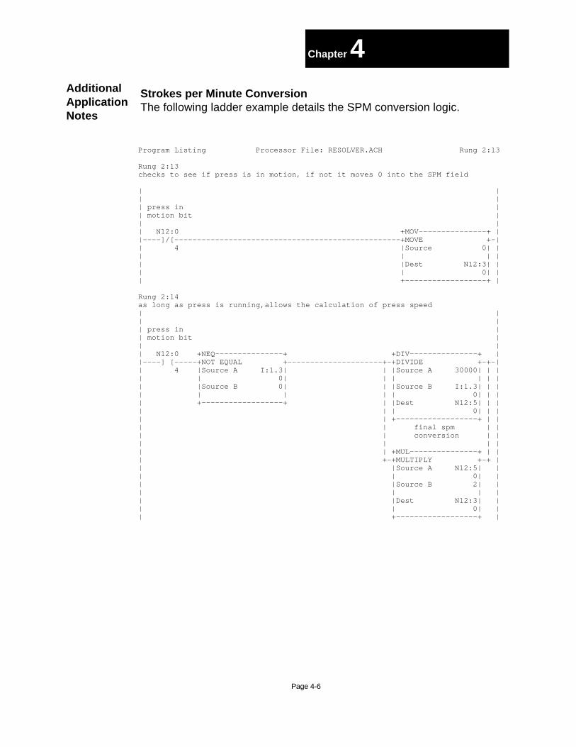
Strokes per Minute ConversionThe following ladder example details the SPM conversion logic.
Page 4-6
Chapter 4AdditionalApplicationNotes
Program Listing Processor File: RESOLVER.ACH Rung 2:13
Rung 2:13checks to see if press is in motion, if not it moves 0 into the SPM field
| || || press in || motion bit || || N12:0 +MOV---------------+ ||----]/[--------------------------------------------------+MOVE +-|| 4 |Source 0| || | | || |Dest N12:3| || | 0| || +------------------+ |
Rung 2:14as long as press is running,allows the calculation of press speed| || || press in || motion bit || || N12:0 +NEQ---------------+ +DIV---------------+ ||----] [-----+NOT EQUAL +---------------------+-+DIVIDE +-+-|| 4 |Source A I:1.3| | |Source A 30000| | || | 0| | | | | || |Source B 0| | |Source B I:1.3| | || | | | | 0| | || +------------------+ | |Dest N12:5| | || | | 0| | || | +------------------+ | || | final spm | || | conversion | || | | || | +MUL---------------+ | || +-+MULTIPLY +-+ || |Source A N12:5| || | 0| || |Source B 2| || | | || |Dest N12:3| || | 0| || +------------------+ |

Download Bits
These two rungs will automatically send out resolver offset everytime onpower-up.
Page 4-7
Chapter 4AdditionalApplicationNotes
Rung 2:4sends out resolver offset to resolver module 100mS after power-up| +TON---------------+ ||----------------------------------------------------+TIMER ON DELAY +-(EN)-|| |Timer T4:0+-(DN) || |Time Base 0.01| || |Preset 100| || |Accum 100| || +------------------+ |
Rung 2:5| T4:0 +MOV---------------+ ||--]/[------------------------------------------------+-+MOVE +-+-|| DN | |Source N12:6| | || | | 0| | || | |Dest O:1.1| | || | | 0| | || | +------------------+ | || | Resolver | || | Download | || | Bit | || | O:1 | || +----( )---------------+ || 2 |

Page 5-1
Chapter 5WiringDiagrams
TRANSMITANALOG
HELM INSTRUMENTCO., INC.
MAUMEE, OHIO USA
TRANSM IT
S3S1
S2S4R1R2
SHIELD
S2 BLACK
S1 RED/WHITE
S3 RED
R2 WHITE/BLACK
R1 WHITE
S4 BLACK/WHITE GE
D C
B
AF
INSIDE BACK VIEW OF7 PIN FEMALE AMPHENOL CONNECTOR

LadderProgramming
Appendix B
B-1
Rung 2:0this rung sets the helm resolver into setup mode when panelview setup/runbutton is set to setup mode; helm resolver must be in setup mode before you canenter an offset value to zero the resolver| Resolver || Resolver Setup Mode || Run\Setup Bit 0 || Mode Bit || N12:0 O:1 ||----]/[--------------------------------------------------------+----(L)-----+-|| 0 | 0 | || | | || | Resolver | || | Run Mode | || | Bit | || | O:1 | || +----(U)-----+ || 1 |
Rung 2:1this rung sets the helm resolver into run mode when the panelview setup/runbutton is set to run mode; the helm resolver should be in this mode for normaloperation| || Resolver Resolver || Run\Setup Run Mode || Mode Bit Bit || N12:0 O:1 ||----] [--------------------------------------------------------+----(L)-----+-|| 0 | 1 | || | Resolver | || | Setup Mode | || | Bit 0 | || | O:1 | || +----(U)-----+ || 0 |

Program Listing Processor File: RESOLVER.ACH Rung 2:2
Rung 2:2| password Panelview || Resolver entered Send || Run\Setup from Offset || Mode Bit panelview Button || N12:0 +EQU---------------+ N12:0 N12:0 +MOV---------------+ ||----]/[-----+EQUAL +----] [------[OSR]---+-+MOVE +-+-|| 0 |Source A N12:9| 1 3 | |Source N12:1| | || | 0| | | 0| | || |Source B N12:4| | |Dest O:1.1| | || | 0| | | 0| | || +------------------+ | +------------------+ | || | +MOV---------------+ | || +-+MOVE +-+ || |Source N12:1| || | 0| || |Dest N12:6| || | 0| || +------------------+ |
Rung 2:3| Panelview password || Clear entered || Offset from || Button panelview || N12:0 +EQU---------------+ +MOV---------------+ ||----] [-----+EQUAL +---------------------+-+MOVE +-+-|| 2 |Source A N12:9| | |Source 0| | || | 0| | | | | || |Source B N12:4| | |Dest O:1.1| | || | 0| | | 0| | || +------------------+ | +------------------+ | || | +MOV---------------+ | || +-+MOVE +-+ || |Source 0| || | | || |Dest N12:1| || | 0| || +------------------+ |
Rung 2:4sends out resolver offset to resolver module 100mS after power-up| +TON---------------+ ||----------------------------------------------------+TIMER ON DELAY +-(EN)-|| |Timer T4:0+-(DN) || |Time Base 0.01| || |Preset 100| || |Accum 100| || +------------------+ |
LadderProgramming
Appendix B
B-2

Program Listing Processor File: RESOLVER.ACH Rung 2:5
Rung 2:5| T4:0 +MOV---------------+ ||--]/[------------------------------------------------+-+MOVE +-+-|| DN | |Source N12:6| | || | | 0| | || | |Dest O:1.1| | || | | 0| | || | +------------------+ | || | Resolver | || | Download | || | Bit | || | O:1 | || +----( )---------------+ || 2 |
Rung 2:6| current || resolver || angle || +MOV---------------+ ||---------------------------------------------------------+MOVE +-|| |Source I:1.1| || | 0| || |Dest N12:7| || | 0| || +------------------+ |
Rung 2:7| motion || detect || time delay || || +TON---------------+ ||----------------------------------------------------+TIMER ON DELAY +-(EN)-|| |Timer T4:1+-(DN) || |Time Base 0.01| || |Preset 10| || |Accum 5| || +------------------+ |
Rung 2:8| time to || check motion || crank detect || angle time delay || || T4:1 T4:1 ||----] [----------------------------------------------+---(RES)--------------+-|| DN | | || | save | || | current to | || | old angle | || | +MOV---------------+ | || +-+MOVE +-+ || |Source N12:7| || | 0| || |Dest N12:8| || | 0| || +------------------+ |
Appendix B
B-3
LadderProgramming

Program Listing Processor File: RESOLVER.ACH Rung 2:9
Rung 2:9| +SUB---------------+ ||---------------------------------------------------------+SUBTRACT +-|| |Source A N12:7| || | 0| || |Source B N12:8| || | 0| || |Dest N12:2| || | 0| || +------------------+ |
Rung 2:10| +GRT---------------+ N12:0 ||-+-+GREATER THAN +-+------------------------------------------------( )--|| | |Source A N12:2| | 5 || | | 0| | || | |Source B 1| | || | | | | || | +------------------+ | || | +LES---------------+ | || +-+LESS THAN +-+ || |Source A N12:2| || | 0| || |Source B -1| || | | || +------------------+ |
Rung 2:11| N12:0 +TOF---------------+ ||--] [-----------------------------------------------+TIMER OFF DELAY +-(EN)-|| 5 |Timer T4:2+-(DN) || |Time Base 0.01| || |Preset 100| || |Accum 100| || +------------------+ |
Rung 2:12| || || press in || motion bit || || T4:2 N12:0 ||--] [-----------------------------------------------------------------( )-----|| DN 4 |
LadderProgramming

Program Listing Processor File: RESOLVER.ACH Rung 2:13
Rung 2:13checks to see if press is in motion, if not it moves 0 into the SPM field
| || || press in || motion bit || || N12:0 +MOV---------------+ ||----]/[--------------------------------------------------+MOVE +-|| 4 |Source 0| || | | || |Dest N12:3| || | 0| || +------------------+ |
Rung 2:14as long as press is running,allows the calculation of press speed| || || press in || motion bit || || N12:0 +NEQ---------------+ +DIV---------------+ ||----] [-----+NOT EQUAL +---------------------+-+DIVIDE +-+-|| 4 |Source A I:1.3| | |Source A 30000| | || | 0| | | | | || |Source B 0| | |Source B I:1.3| | || | | | | 0| | || +------------------+ | |Dest N12:5| | || | | 0| | || | +------------------+ | || | final spm | || | conversion | || | | || | +MUL---------------+ | || +-+MULTIPLY +-+ || |Source A N12:5| || | 0| || |Source B 2| || | | || |Dest N12:3| || | 0| || +------------------+ |
Rung 2:15| ||-------------------------------------+END+------------------------------------|
| |
----------------------------------|| |
LadderProgramming