Embed Size (px)
Citation preview
Improved Conductivity Analysis in Desalination
ProcessesBy Ryo Hashimoto, Emerson Process Management, Rosemount Analytical
onductivity measurements are widely used in a variety of industries and applications, including leak detection, clean-in-place, water treatment, interface
detection, and notably, in desalination. As the need for fresh water escalates worldwide, the demand for desalination plants continues to increase dramatically, and one of the key measurements critical in desalination is conductivity. Drinking water desalination plants, both thermal (evaporative) and membrane (reverse osmosis), make extensive use of conductivity to monitor how completely dissolved ionic solids are being removed from the brackish raw water.
There are two basic desalination technologies: membrane separation done through reverse osmosis and distillation. Reverse osmosis (RO) consumes less power than distillation, so it’s often the preferred method. In the RO process, raw seawater or brackish groundwater is pumped at high pressure against a semi-permeable membrane. The membrane permits water to pass through, but blocks and rejects dissolved solids as concentrated brine. Today’s RO membranes can reject up to 99 percent of the dissolved solids in the feedwater.
Measuring Membrane Performance with ConductivityIn membrane-based reverse osmosis, pressure forces water through the membrane to reject most solute ions and molecules while allowing water of very low mineral content to pass through. Higher pressures increase the flux of water through the membrane, which is good, as it also leads to better permeate quality. The concentration of dissolved solids on the feedwater side of the membrane increases with increased pressure, causing the brine to escalate. This condition results in fouling or build-up on the membranes, increasing maintenance and shortening membrane life.
The most useful measurement in the separation process itself is conductivity. The objectionable solids in seawater or brackish water are primarily ionic, so conductivity is a cost effective and easy way of measuring membrane performance. Typically, the conductivity of both the feedwater and permeate are measured, allowing continuous calculation of percent solids rejection by the membrane. Unexpected
changes in performance immediately alert plant operators to a problem.
For this reason, conductivity is an important measurement in the desalination process, but while plant operators may use conductivity frequently, they don’t necessarily understand the theory and application for how the measurement is performed. It’s important to understand the various types of conductivity, where they are appropriately used, and how conductivity interacts with temperature and other factors that can ultimately impact the performance of conductivity measurements.
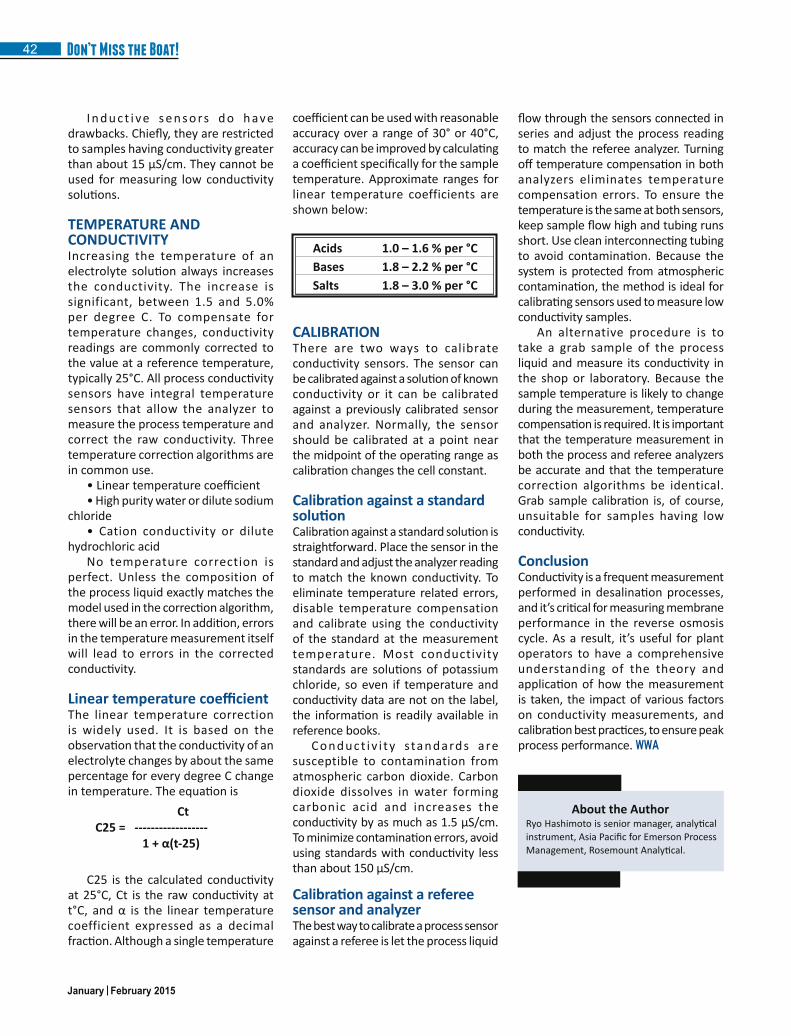
MEASUREMENT OF CONDUCTIVITYConductivity is a measure of how well a solution conducts electricity. To carry a current, a solution must contain charged particles, or ions. Most conductivity measurements are made in aqueous solutions, and the ions responsible for the conductivity come from electrolytes dissolved in the water. Salts, acids, and bases are all electrolytes, see table 1.
Category Substance
Salts Sodium chloride and magnesium sulfate
Acids Hydrochloric acid and acetic acid
Bases Sodium hydroxide and ammonia
Although water itself is not an electrolyte, it does have a very small conductivity, implying that at least some ions are present. The ions are hydrogen and hydroxide, and they originate from the dissociation of molecular water. See Figure 1
Conductivity is not specific. It measures the total concentration of ions in solution. It cannot distinguish one electrolyte or ion from another.
Not all aqueous solutions have conductivity. Solutions of non-electrolytes, for example sugar or alcohol, have no conductivity because neither sugar nor alcohol contains ions nor do they produce ions when dissolved in water.
Table 1
January February 2015
Don’t Miss the Boat!40
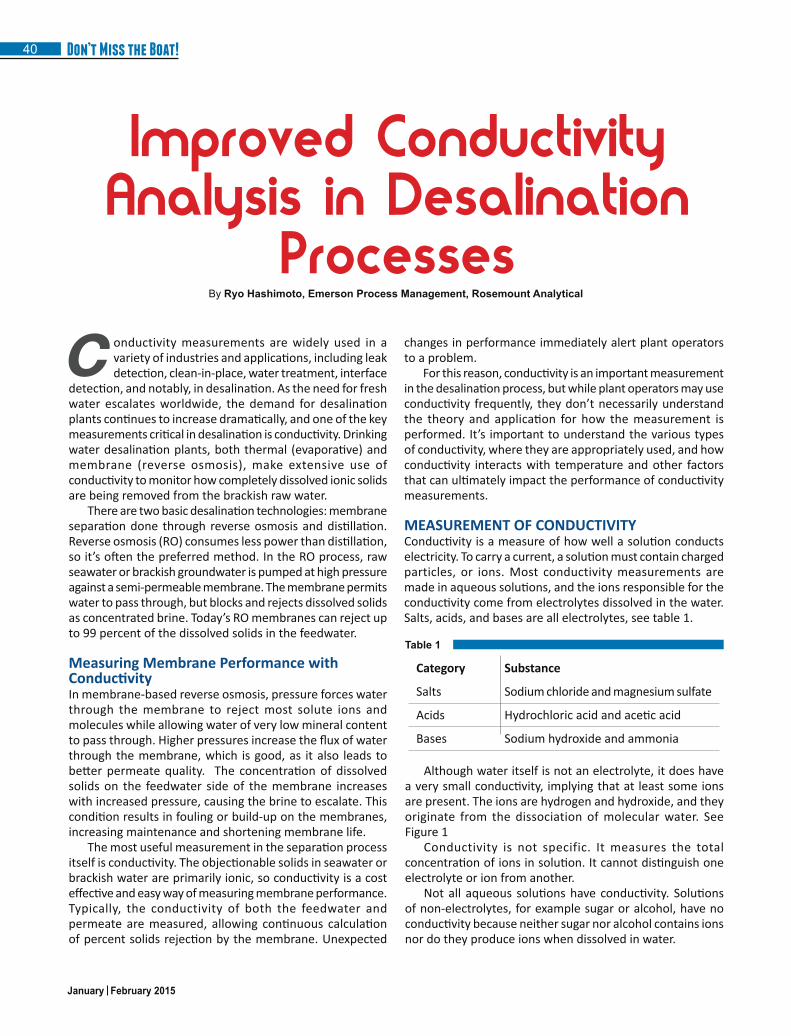
There are two types of conductivity measurement: contacting and inductive. The choice of which to use depends on the amount of conductivity, the corrosiveness of the liquid, and the amount of suspended solids. Generally, the inductive method is better when the conductivity is high, the liquid is corrosive, or suspended solids are present
ContactingConductivityMost contacting conductivity sensors consist of two metal electrodes, usually stainless steel or titanium, in contact with the electrolyte solution. The analyzer applies an alternating voltage to the electrodes. The electric field causes the ions to move back and forth producing a current. Because the charge carriers are ions, the current is called an ionic current. The analyzer measures the current and uses Ohm’s law to calculate the resistance of the solution (resistance = voltage/current). The conductance of the solution is the reciprocal of the resistance.
Contacting conductivity measurements are restricted to applications where the conductivity is fairly low and the sample is non-corrosive and free of suspended solids. It’s ideal for measuring high purity water in semiconductor, steam electric power, and pharmaceutical plants, but in desalination processes, the preferred method is inductive conductivity.
InductiveConductivityInductive conductivity is sometimes called toroidal or electrodeless conductivity. An inductive sensor consists of two wire-wound metal toroids encased in a corrosion-resistant plastic body. One toroid is the drive coil, the other is the receive coil. The sensor is immersed in the conductive liquid. The analyzer applies an alternating voltage to the drive coil, which induces a voltage in the liquid surrounding the coil. The voltage causes an ionic current to flow proportional to the conductance of the liquid. The ionic current induces an electronic current in the receive coil, which the analyzer measures. The induced current is directly proportional to the conductance of the solution. See Figure 2.
The current in the receive coil depends on the number of windings in the drive and receive coils and the physical dimensions of the sensor, which defines the volume of sample through which the ionic current flows. The number
of windings and the dimensions of the sensor are described by the cell constant. As in the case of contacting sensors, the product of the cell constant and conductance is the conductivity.
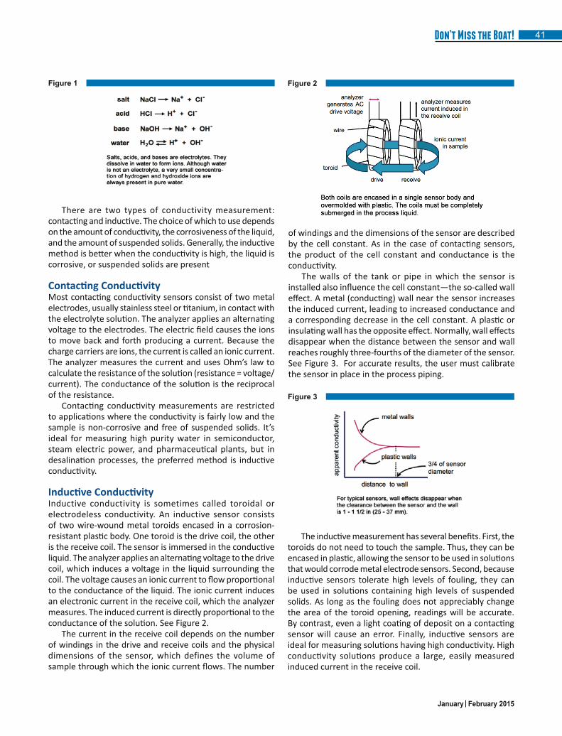
The walls of the tank or pipe in which the sensor is installed also influence the cell constant—the so-called wall effect. A metal (conducting) wall near the sensor increases the induced current, leading to increased conductance and a corresponding decrease in the cell constant. A plastic or insulating wall has the opposite effect. Normally, wall effects disappear when the distance between the sensor and wall reaches roughly three-fourths of the diameter of the sensor. See Figure 3. For accurate results, the user must calibrate the sensor in place in the process piping.
Figure 2
Figure 3
The inductive measurement has several benefits. First, the toroids do not need to touch the sample. Thus, they can be encased in plastic, allowing the sensor to be used in solutions that would corrode metal electrode sensors. Second, because inductive sensors tolerate high levels of fouling, they can be used in solutions containing high levels of suspended solids. As long as the fouling does not appreciably change the area of the toroid opening, readings will be accurate. By contrast, even a light coating of deposit on a contacting sensor will cause an error. Finally, inductive sensors are ideal for measuring solutions having high conductivity. High conductivity solutions produce a large, easily measured induced current in the receive coil.
Figure 1
January February 2015
41Don’t Miss the Boat!
CtC25 = ------------------1+α(t-25)
C25 is the calculated conductivity at 25°C, Ct is the raw conductivity at t°C, and α is the linear temperature coefficient expressed as a decimal fraction. Although a single temperature
Acids 1.0 – 1.6 % per °CBases 1.8 – 2.2 % per °CSalts 1.8 – 3.0 % per °C
CALIBRATIONThere are two ways to calibrate conductivity sensors. The sensor can be calibrated against a solution of known conductivity or it can be calibrated against a previously calibrated sensor and analyzer. Normally, the sensor should be calibrated at a point near the midpoint of the operating range as calibration changes the cell constant.
CalibrationagainstastandardsolutionCalibration against a standard solution is straightforward. Place the sensor in the standard and adjust the analyzer reading to match the known conductivity. To eliminate temperature related errors, disable temperature compensation and calibrate using the conductivity of the standard at the measurement temperature. Most conductivity standards are solutions of potassium chloride, so even if temperature and conductivity data are not on the label, the information is readily available in reference books.
Conduct iv i ty standards are susceptible to contamination from atmospheric carbon dioxide. Carbon dioxide dissolves in water forming carbonic acid and increases the conductivity by as much as 1.5 μS/cm. To minimize contamination errors, avoid using standards with conductivity less than about 150 μS/cm.
CalibrationagainstarefereesensorandanalyzerThe best way to calibrate a process sensor against a referee is let the process liquid
Ryo Hashimoto is senior manager, analytical instrument, Asia Pacific for Emerson Process Management, Rosemount Analytical.
About the Author
I n d u c t i ve s e n s o rs d o h ave drawbacks. Chiefly, they are restricted to samples having conductivity greater than about 15 μS/cm. They cannot be used for measuring low conductivity solutions.
TEMPERATURE AND CONDUCTIVITYIncreasing the temperature of an electrolyte solution always increases the conductivity. The increase is significant, between 1.5 and 5.0% per degree C. To compensate for temperature changes, conductivity readings are commonly corrected to the value at a reference temperature, typically 25°C. All process conductivity sensors have integral temperature sensors that allow the analyzer to measure the process temperature and correct the raw conductivity. Three temperature correction algorithms are in common use.
• Linear temperature coefficient• High purity water or dilute sodium
chloride• Cation conductivity or dilute
hydrochloric acidNo temperature correction is
perfect. Unless the composition of the process liquid exactly matches the model used in the correction algorithm, there will be an error. In addition, errors in the temperature measurement itself will lead to errors in the corrected conductivity.
LineartemperaturecoefficientThe linear temperature correction is widely used. It is based on the observation that the conductivity of an electrolyte changes by about the same percentage for every degree C change in temperature. The equation is
coefficient can be used with reasonable accuracy over a range of 30° or 40°C, accuracy can be improved by calculating a coefficient specifically for the sample temperature. Approximate ranges for linear temperature coefficients are shown below:
flow through the sensors connected in series and adjust the process reading to match the referee analyzer. Turning off temperature compensation in both analyzers eliminates temperature compensation errors. To ensure the temperature is the same at both sensors, keep sample flow high and tubing runs short. Use clean interconnecting tubing to avoid contamination. Because the system is protected from atmospheric contamination, the method is ideal for calibrating sensors used to measure low conductivity samples.
An alternative procedure is to take a grab sample of the process liquid and measure its conductivity in the shop or laboratory. Because the sample temperature is likely to change during the measurement, temperature compensation is required. It is important that the temperature measurement in both the process and referee analyzers be accurate and that the temperature correction algorithms be identical. Grab sample calibration is, of course, unsuitable for samples having low conductivity.
ConclusionConductivity is a frequent measurement performed in desalination processes, and it’s critical for measuring membrane performance in the reverse osmosis cycle. As a result, it’s useful for plant operators to have a comprehensive understanding of the theory and application of how the measurement is taken, the impact of various factors on conductivity measurements, and calibration best practices, to ensure peak process performance. WWA
January February 2015
Don’t Miss the Boat!42


![Improved Electrical Conductivity of a Carbon Nanotube Mat …carbonlett.org/Upload/files/CARBONLETT/[243-247]-08.pdf · Improved electrical conductivity of a thermoplastic CNT mat](https://img.pdfslide.net/doc/110x75/5c66db0f09d3f252168cf940/improved-electrical-conductivity-of-a-carbon-nanotube-mat-243-247-08pdf-improved.jpg)