Embed Size (px)
Citation preview

Improved decoding of staircase codes
Citation for published version (APA):Lei, Y., Chen, B., Liga, G., Deng, X., Cao, Z., Li, J., Xu, K., & Alvarado, A. (2019). Improved decoding ofstaircase codes: the soft-aided bit-marking (SABM) algorithm. arXiv, [1902.01178v1].https://arxiv.org/abs/1902.01178
Document status and date:Published: 04/02/2019
Document Version:Accepted manuscript including changes made at the peer-review stage
Please check the document version of this publication:
• A submitted manuscript is the version of the article upon submission and before peer-review. There can beimportant differences between the submitted version and the official published version of record. Peopleinterested in the research are advised to contact the author for the final version of the publication, or visit theDOI to the publisher's website.• The final author version and the galley proof are versions of the publication after peer review.• The final published version features the final layout of the paper including the volume, issue and pagenumbers.Link to publication
General rightsCopyright and moral rights for the publications made accessible in the public portal are retained by the authors and/or other copyright ownersand it is a condition of accessing publications that users recognise and abide by the legal requirements associated with these rights.
• Users may download and print one copy of any publication from the public portal for the purpose of private study or research. • You may not further distribute the material or use it for any profit-making activity or commercial gain • You may freely distribute the URL identifying the publication in the public portal.
If the publication is distributed under the terms of Article 25fa of the Dutch Copyright Act, indicated by the “Taverne” license above, pleasefollow below link for the End User Agreement:www.tue.nl/taverne
Take down policyIf you believe that this document breaches copyright please contact us at:[email protected] details and we will investigate your claim.
Download date: 29. Jan. 2022
PREPRINT, FEBRUARY 5, 2019. 1
Improved Decoding of Staircase Codes: TheSoft-aided Bit-marking (SABM) Algorithm
Yi Lei, Bin Chen, Member, IEEE, Gabriele Liga, Xiong Deng, Zizeng Cao, Jianqiang Li, Senior Member, IEEE,Kun Xu, Member, IEEE, Alex Alvarado, Senior Member, IEEE
Abstract—Staircase codes (SCCs) are typically decoded usingiterative bounded-distance decoding (BDD) and hard decisions.In this paper, a novel decoding algorithm is proposed, whichpartially uses soft information from the channel. The proposedalgorithm is based on marking certain number of highly reliableand highly unreliable bits. These marked bits are used to improvethe miscorrection-detection capability of the SCC decoder andthe error-correcting capability of BDD. For SCCs with 2-error-correcting Bose-Chaudhuri-Hocquenghem component codes, ouralgorithm improves upon standard SCC decoding by up to0.30 dB at a bit-error rate (BER) of 10−7. The proposedalgorithm is shown to achieve almost half of the gain achievableby an idealized decoder with this structure. A complexity analysisbased on the number of additional calls to the component BDDdecoder shows that the relative complexity increase is only around4% at a BER of 10−4. This additional complexity is shownto decrease as the channel quality improves. Our algorithm isalso extended (with minor modifications) to product codes. Thesimulation results show that in this case, the algorithm offersgains of up to 0.44 dB at a BER of 10−8.
Index Terms—Optical communication systems, staircase codes,product codes, hard decision, iterative bounded distance decod-ing, marked bits.
I. INTRODUCTION AND MOTIVATION
Forward error correction (FEC) is required in optical com-munication systems to meet the ever increasing data demandsin optical transport networks (OTNs). FEC codes that canboost the net coding gain (NCG) are of key importance. AReed-Solomon (RS) code with parameters of (255, 239) wasthe first standardized FEC code for OTNs in the ITU-T Rec-ommendation G.975 [1]. For an output bit error ratio (BER)of 10−15, the NCG of RS(255, 239) is 6.2 dB. In order toincrease transmission data rate and distance, several super FECcodes were considered in the ITU-T Recommendation G.975.1
Y. Lei is with State Key Laboratory of Information of Photonics andOptical Communications, Beijing University of Posts and Telecommunications(BUPT), China and the Signal Processing Systems (SPS) Group, Departmentof Electrical Engineering, Eindhoven University of Technology, The Nether-lands (e-mail:[email protected]).
A. Alvarado, B. Chen, G. Liga and X. Deng are with the Signal ProcessingSystems (SPS) Group, Department of Electrical Engineering, EindhovenUniversity of Technology, The Netherlands. Z. Cao and B. Chen are withthe Electro-Optical Communications (ECO) Group, Department of ElectricalEngineering, Eindhoven University of Technology, The Netherlands (e-mails:{a.alvarado, b.c.chen,g.liga,x.deng,z.cao}@tue.nl).
J. Li and K. Xu are with State Key Laboratory of Informationof Photonics and Optical Communications, Beijing University of Postsand Telecommunications (BUPT), China (e-mails: [email protected],[email protected])
This work was presented in part at the International Symposium on TurboCodes & Iterative Information Processing 2018, Hong Kong, China, Dec.2018.
[2]. Most of these super FECs utilize two concatenated FECcodes, such as: BCH(3860, 3824, 3)+BCH(2040, 1930, 10)codes1 , RS(1023, 1007)+BCH(2047, 1952, 8) codes, etc. Theachieved NCG can be up to 8.99 dB at a BER of 10−15.
OTNs are currently targeting data rates of 400 Gb/s andbeyond [3], [4]. In this scenario, FEC codes with higher NCGare highly desired. Soft-decision (SD) FEC codes provide largeNCGs, however, they are not the best candidates for very highdata rate applications due to their high power consumptionand decoding latency. For applications with strict latencyand complexity requirements (e.g., short reach), simple butpowerful hard-decision (HD) FEC codes, e.g., product codes(PCs) [5] and staircase codes (SCCs) [6], [7], have receivedconsiderable attention: PC has been adopted (as an inner code)in the subclass I.5 of G.975.1 [2], while SCC is part of the400ZR Implementation Agreement (as an outer code) in theOptical Internetworking Forum [8]. SCC is also recommendedfor 100G optical transport unit (OTU) order 4 for long-reachapplications in the ITU-T Recommendation G.709.2/Y.1331.2[9]. In [10], product and staircase decodes are implementedin very-large-scale integration system, which reach more than1 Tb/s information throughputs with only energy efficienciesof around 2 pJ/bit. Recently, low-complexity concatenatedFEC and adaptive coded modulation schemes have also beenstudied to combine the advantages of soft- and hard-decisiondecoders [11], [12].
Both SCCs and PCs are based on simple component codes,Bose-Chaudhuri-Hocquenghem (BCH) codes being the mostpopular ones. The decoding is done iteratively based onbounded-distance decoding (BDD) for the component codes.Although very simple, one drawback of BDD is that itserror-correcting capability is limited to t = b(d0 − 1)/2c,where d0 is the minimum Hamming distance (MHD) of thecomponent code [13]. BDD can detect more than t errors,but cannot correct them. In some cases, BDD may alsoerroneously decode a received sequence with more than terrors, a situation known as a miscorrection. Miscorrectionsare known to degrade the performance of iterative BDD.To prevent miscorrections and/or extend the error correctingcapability, several methods have been studied in the literature.In what follows we review those methods.
To prevent miscorrections in SCCs, the authors of [14]proposed rejecting bit-flips from the decoding of bit sequencesassociated with the last SCC block if they conflict with a
1Throughout this paper we use nc, kc, and t to denote the codewordlength, information length, and error-correcting capability, resp. BCH codesare denoted as BCH(nc, kc, t).
arX
iv:1
902.
0117
8v1
[ee
ss.S
P] 4
Feb
201
9

PREPRINT, FEBRUARY 5, 2019. 2
zero-syndrome codeword from the previous block. As pointedout in [15, Sec. I], the obtained gains of [14] are expectedto be limited. An anchor-based decoding algorithm has beenproposed in [15], [16], where some bit sequences are labeledas anchor codewords. These sequences are thought to havebeen decoded without miscorrections. Decoding results thatare inconsistent with anchor codewords are discarded. It hasbeen demonstrated that this algorithm works well with bothSCCs and PCs. The algorithm of [16] outperforms [14], butit suffers from an increased complexity as anchor codewordsneed to be tracked during iterative BDD. Very recently, amodified iterative BDD for PCs was proposed in [17]–[20].In this algorithm, channel reliabilities are used to perform thefinal HD at the output of BDD, instead of directly acceptingthe decoding result. Large gains are obtained, but it requiresadditional memory (and processing) as all the soft informationneeds to be saved. Moreover, its effectiveness for SCCs hasnot yet been reported in the literature.
To extend the error correcting capability, Chase proposedthree kinds of algorithms to decode block codes with channelsoft information [21]. In this class of algorithm, each bit isaccompanied with an analog weight, according to the softinformation. During the decoding, the algorithms will generatea sequence of test patterns first, then decode all of themand choose the decoding result with lowest analog weightas the final output. Through this way, the error correctingcapability can be extended from b(d0 − 1)/2c to d0 − 1. Themain drawback of these three algorithms is that the decoderneeds to decode at least b(d0/2) + 1c test patterns (whilein fact, not all of them are necessary). This significantlyincreases the decoding complexity and latency. In addition,algorithm 3 in [21] behaves similarly to erasure decoding thatthe sequence of test patterns is equivalent to the sequence oferasures described in [22, Sec. 6.6]. Both Chase decoders anderasure decoding were not designed to take miscorrections intoaccount. In addition, based on chase decoder, the authors of[23] have considered to use soft-input/soft-output decoder todecode each component code within all iterations. However,the achieved additional gain is only 0.30 dB for large blocksize, at the expense of greatly increased complexity.
In this paper, we propose the soft-aided bit-marking(SABM) algorithm to improve the decoding of SCCs as wellas PCs. As high order modulation formats are often usedin modern optical communication systems, the performanceof the proposed SABM algorithm under different modulationformats was investigated. The presented gains are achieved bymarking highly reliable and highly unreliable bits, an idea wefirst proposed in [24] and also experimentally validated in amulti-span hybrid-amplified system in [25]. Unlike previousworks, the proposed SABM algorithm jointly increases themiscorrection-detection capability of the SCC decoder andthe error-correcting capability of BDD. The main feature ofthe proposed algorithm is its low complexity, as explained inwhat follows. For SCCs, the SABM algorithm only requiresmodifications to the decoding structure of the last block ofeach decoding window. Furthermore, in the SABM algorithmeach component code needs to be decoded at most twice. Also,the algorithm is based on marking bits only, and thus, no soft
Proposed Receiver
Standard HD-Receiver
StaircaseEncoder
info.bits M -PAM Mapper
{0, 1}m −→ S
bl,1
bl,m
... √ρ
xl
zl
ylHD-Demapper{0, 1}m ←− R
StaircaseDecoder
bl,1
bl,m
...
info.bits
LLRCalculation
LLRMarking
|λl,1|
|λl,m|
...
· · ·ql,1 ql,m
Fig. 1: System model under consideration.
bits (log-likelihood ratios, LLRs) need to be stored. Finally,marked bits do not need to be tracked during the iterativeprocess either.
The remainder of the paper is organized as follows. In Sec.II, we present the system model we consider and introducethe principles of SCCs and BDD. In Sec. III, we describe theproposed SABM algorithm. Some examples are also gave toexplain how it works. In Sec. IV, we present the simulationresults for SCCs, and discuss the complexity of the SABMalgorithm. In Sec. V, we extend this algorithm to PCs andinvestigate the performance. Finally, we conclude this paperin Sec. VI.
II. SYSTEM MODEL, SCCS, AND BDD
A. System Model
As shown in Fig. 1, information bits are encoded by astaircase encoder and then mapped to symbols xl taken froman equally-spaced M -ary Pulse Amplitude Modulation (PAM)constellation S = {s1, s2, . . . , sM} with M = 2m points,where l is the discrete time index. The bit-to-symbol mappingis the binary reflected Gray code. The received signal isyl =
√ρxl + zl, where zl is zero-mean unit-variance additive
white Gaussian noise (AWGN).The standard HD receiver structure for SCCs uses an HD-
based demapper to estimate the code bits, which are then fedto the decoder (green area in Fig. 1). In this paper, we considera receiver architecture where the HD-FEC decoder uses softinformation from the channel. This soft information is typi-cally represented using LLRs, calculated as [26, eq. (3.50)]
λl,k =∑
b∈{0,1}(−1)b log
∑i∈Ik,b
exp(− (yl −√ρsi)2
2
), (1)
with k = 1, . . . ,m, and where b denotes bit negation. In (1),the set Ik,b enumerates all the constellation points in S whosekth bit ci,k is b, i.e., Ik,b , {i = 1, 2, . . . ,M : ci,k = b}.
The proposed structure is shown in Fig. 1 (red area). Inthis structure, apart from the HD-estimated bits bl,1, . . . , bl,m,a sequence of marked bits will also be made available to thedecoder. We call this architecture soft-aided (SA) HD-FECdecoding. These marked bits are denoted by ql,k and can be:highly reliable bits (HRBs), highly unreliable bits (HUBs), orunmarked bits. The marking is made based on the absolute
PREPRINT, FEBRUARY 5, 2019. 3
BT0 B1
BT2 B3
BT4 B5
w
w
p
p
. . .
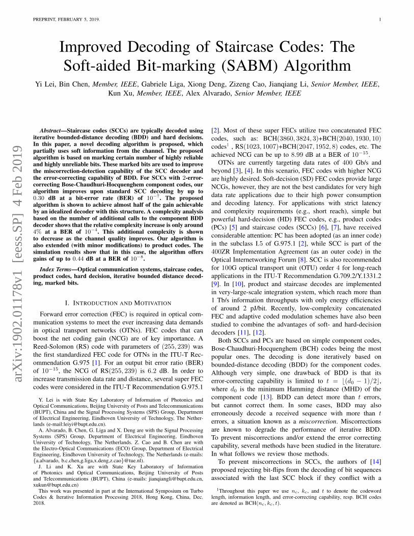
Fig. 2: Staircase structure of SCCs considered in this paper.
value of the LLRs |λl,k|. More details about the markingprocedure and how this can be exploited by the decoder willbe given in Sec. III.
B. Staircase Codes
Fig. 2 shows the staircase structure of SCCs we consider inthis paper, where block B0 is initialized to all zeros. Each sub-sequent SCC block Bi, i = 1, 2, . . ., is composed of w(w−p)information bits (white areas) and wp parity bits (gray areas).Each row of the matrix [BT
i−1Bi] ∀i > 1 is a valid codewordin a component code C. We consider the component code Cto be a binary code with parameters (nc, kc, t). Then, w andp are given by: w = nc/2 and p = nc − kc. The code rateR of the SCC is R = 1 − p/w = 2kc/nc − 1. Throughoutthis paper, the component codes C considered are extended(by 1 additional parity bit) BCH codes. The mapping betweencode bits and symbols is done by reading row-by-row the SCCblocks Bi, i = 1, 2, . . .
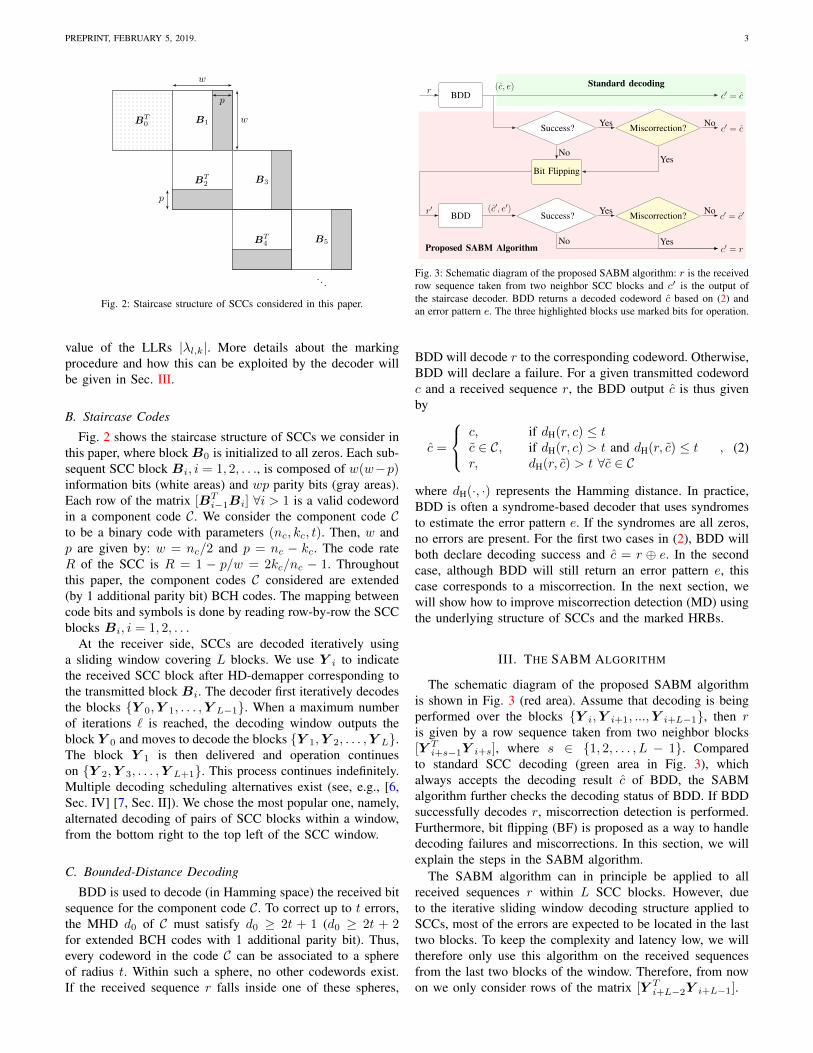
At the receiver side, SCCs are decoded iteratively usinga sliding window covering L blocks. We use Y i to indicatethe received SCC block after HD-demapper corresponding tothe transmitted block Bi. The decoder first iteratively decodesthe blocks {Y 0,Y 1, . . . ,Y L−1}. When a maximum numberof iterations ` is reached, the decoding window outputs theblock Y 0 and moves to decode the blocks {Y 1,Y 2, . . . ,Y L}.The block Y 1 is then delivered and operation continueson {Y 2,Y 3, . . . ,Y L+1}. This process continues indefinitely.Multiple decoding scheduling alternatives exist (see, e.g., [6,Sec. IV] [7, Sec. II]). We chose the most popular one, namely,alternated decoding of pairs of SCC blocks within a window,from the bottom right to the top left of the SCC window.
C. Bounded-Distance Decoding
BDD is used to decode (in Hamming space) the received bitsequence for the component code C. To correct up to t errors,the MHD d0 of C must satisfy d0 ≥ 2t + 1 (d0 ≥ 2t + 2for extended BCH codes with 1 additional parity bit). Thus,every codeword in the code C can be associated to a sphereof radius t. Within such a sphere, no other codewords exist.If the received sequence r falls inside one of these spheres,
BDD
Success? Miscorrection?
Bit Flipping
BDD Success? Miscorrection?
c′ = r
c′ = c′
c′ = c
c′ = cr
Yes No
NoYes
r′ (c′, e′) Yes No
No Yes
(c, e)
Proposed SABM Algorithm
Standard decoding
Fig. 3: Schematic diagram of the proposed SABM algorithm: r is the receivedrow sequence taken from two neighbor SCC blocks and c′ is the output ofthe staircase decoder. BDD returns a decoded codeword c based on (2) andan error pattern e. The three highlighted blocks use marked bits for operation.
BDD will decode r to the corresponding codeword. Otherwise,BDD will declare a failure. For a given transmitted codewordc and a received sequence r, the BDD output c is thus givenby
c =
c, if dH(r, c) ≤ tc ∈ C, if dH(r, c) > t and dH(r, c) ≤ tr, dH(r, c) > t ∀c ∈ C
, (2)
where dH(·, ·) represents the Hamming distance. In practice,BDD is often a syndrome-based decoder that uses syndromesto estimate the error pattern e. If the syndromes are all zeros,no errors are present. For the first two cases in (2), BDD willboth declare decoding success and c = r ⊕ e. In the secondcase, although BDD will still return an error pattern e, thiscase corresponds to a miscorrection. In the next section, wewill show how to improve miscorrection detection (MD) usingthe underlying structure of SCCs and the marked HRBs.
III. THE SABM ALGORITHM
The schematic diagram of the proposed SABM algorithmis shown in Fig. 3 (red area). Assume that decoding is beingperformed over the blocks {Y i,Y i+1, ...,Y i+L−1}, then ris given by a row sequence taken from two neighbor blocks[Y T
i+s−1Y i+s], where s ∈ {1, 2, . . . , L − 1}. Comparedto standard SCC decoding (green area in Fig. 3), whichalways accepts the decoding result c of BDD, the SABMalgorithm further checks the decoding status of BDD. If BDDsuccessfully decodes r, miscorrection detection is performed.Furthermore, bit flipping (BF) is proposed as a way to handledecoding failures and miscorrections. In this section, we willexplain the steps in the SABM algorithm.
The SABM algorithm can in principle be applied to allreceived sequences r within L SCC blocks. However, dueto the iterative sliding window decoding structure applied toSCCs, most of the errors are expected to be located in the lasttwo blocks. To keep the complexity and latency low, we willtherefore only use this algorithm on the received sequencesfrom the last two blocks of the window. Therefore, from nowon we only consider rows of the matrix [Y T
i+L−2Y i+L−1].
PREPRINT, FEBRUARY 5, 2019. 4
|λl,k|4 2 3 0.5 1 22
1.7 2.5 12 1 6 15
3 0.2 0.7 1.5 6 5
1 2 3 4 5 6
Y i
(1, 2)
123456
Y Ti+1
1 2 3 4 5 6
Y i+2
(3, 1)
123456
Y Ti+3
(4, 1)
(4, 3)
(4, 5)
1 2 3 4 5 6
Y i+4
...
. . .
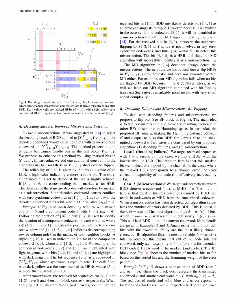
Fig. 4: Decoding example (w = 6, L = 5, t = 2): black crosses are receivederrors after channel transmission and red crosses indicate miscorrections afterBDD. Dark yellow cells are marked HRBs (δ = 10), while light yellow cellsare marked HUBs. Lighter yellow colors indicate a smaller value of |λl,k|.
A. Decoding Success: Improved Miscorrection Detection
To avoid miscorrections, it was suggested in [14] to rejectthe decoding result of BDD applied to [Y T
i+L−2Y i+L−1] if thedecoded codeword would cause conflicts with zero-syndromecodewords in [Y T
i+L−3Y i+L−2]. This method protects bits inY i+L−2 but cannot handle bits in the last block Y i+L−1.We propose to enhance this method by using marked bits inY i+L−1. In particular, we add one additional constraint to thealgorithm in [14]: no HRBs in Y i+L−1 shall ever be flipped.
The reliability of a bit is given by the absolute value of itsLLR, a high value indicating a more reliable bit. Therefore,a threshold δ is set to decide if the bit is highly reliable.If |λl,k| > δ, the corresponding bit is marked as an HRB.The decision of the staircase decoder will therefore be markedas a miscorrection if the decoded codeword causes conflictswith zero-syndrome codewords in [Y T
i+L−3Y i+L−2], or if thedecoded codeword flips a bit whose LLR satisfies |λl,k| > δ.
Example 1: Fig. 4 shows a decoding window with w = 6and L = 5 and a component code C with t = 2 (d0 = 6).Following the notation of [16], a pair (i, j) is used to specifythe location of a component codeword in each window, wherei ∈ {1, 2, . . . , L−1} indicates the position relative to the cur-rent window and j ∈ {1, 2, . . . , w} indicates the correspondingrow or column index in the matrix of two neighbor blocks. Atriple (i, j, k) is used to indicate the kth bit in the componentcodeword (i, j), where k ∈ {1, 2, . . . , 2w}. For example, thecomponent codewords (1, 2) and (3, 1) are highlighted withlight magenta, while bits (1, 2, 11) and (3, 1, 4) are highlightedwith dark magenta. The bit sequence (3, 1) is a codeword in[Y T
i+2Y i+3] whose syndrome is equal to zero. The cells filledwith dark yellow are the ones marked as HRBs whose |λl,k|is more than δ, while δ = 10.
After transmission, the received bit sequences for (4, 1) and(4, 3) have 5 and 4 errors (black crosses), respectively. Whenapplying BDD, miscorrections (red crosses) occur. For the
received bits in (4, 1), BDD mistakenly detects bit (4, 1, 1) asan error and suggests to flip it. However, because it is involvedin the zero-syndrome codeword (3, 1), it will be identified asa miscorrection by both our MD algorithm and by the one in[14]. For the received bits in (4, 3), however, the suggestedflipping bit (4, 3, 5) in Y i+L−2 is not involved in any zero-syndrome codewords, and thus, [14] would fail to detect thismiscorrection. The bit (4, 3, 9) is a HRB, and thus, our MDalgorithm will successfully identify it as a miscorrection. M
The MD algorithm in [14] does not always detect themiscorrections. The new rule we introduced (never flip HRBsin Y i+L−1) is only heuristic and does not guarantee perfectMD either. For example, our MD algorithm fails when no bitsare flipped by BDD because r = c ∈ C. Nevertheless, as wewill see later, our MD algorithm combined with bit flipping(see next Sec.) gives remarkably good results with very smalladded complexity.
B. Decoding Failures and Miscorrections: Bit Flipping
To deal with decoding failures and miscorrections, wepropose to flip bits (see BF block in Fig. 3). The main ideais to flip certain bits in r and make the resulting sequence r′
(after BF) closer to c in Hamming space. In particular, theproposed BF aims at making the Hamming distance betweenr′ and c equal to t, so that BDD can correct r′ to the trans-mitted codeword c. Two cases are considered by our proposedalgorithm: (1) decoding failures, and (2) miscorrections.
Case 1 (Decoding Failures): We target received sequenceswith t + 1 errors. In this case, we flip a HUB with thelowest absolute LLR. The intuition here is that this markedbit was indeed one flipped by the channel. In the cases wherethe marked HUB corresponds to a channel error, the errorcorrection capability of the code C is effectively increased by1 bit.
Case 2 (Miscorrections): We target miscorrections whereBDD chooses a codeword c ∈ C at MHD of c. The intuitionhere is that most of the miscorrections caused by BDD willresult in codewords at MHD from the transmitted codeword.When a miscorrection has been detected, our algorithm calcu-lates the number of errors detected by BDD. This is equal todH(r, c) = wH(e). Then, our algorithm flips d0−wH(e)−t bits,which in some cases will result in r′ that satisfy dH(c, r′) = t.This will lead BDD to find the correct codeword. More detailsare given in Examples 2 and 3. Again using the intuition thatbits with the lowest reliability are the most likely channelerrors, our BF algorithm flips the most unreliable d0−wH(e)−tbits. In practice, this means that out of nc code bits percodeword, only d0−wH(e)− t < t+ 1 (or t+ 2 for extendedBCH codes) HUBs need to be marked (and sorted). The BFblock (see Fig. 3) chooses the number of marked bits to flipbased on this sorted list and the Hamming weight of the errorpattern.
Example 2: Fig. 5 shows a representation of BDD (t = 2and d0 = 6), where the black dots represent the transmittedcodeword c and another codeword c ∈ C with dH(c, c) = d0.The red dashed circle and solid blue circles correspond tolocations of r for Cases 1 and 2, respectively. The bit sequence
PREPRINT, FEBRUARY 5, 2019. 5
c cd0 = 6
t = 2 t = 2
dH(r, c) = 1dH(r, c) = 2
dH(r, c) = 3
dH(r, c) = 5dH(r, c) = 4
· · · · · ·
Fig. 5: Schematic representation of BDD: c is the transmitted codeword andc ∈ C is another codeword at MHD d0 = 6. The circles around c show thepossible locations of r with 1, 2, .... errors from inside to outside in turn,while black solid circles indicate cases that BDD will decode successfully.Diamonds indicate four possible locations, where miscorrection happens.
(4, 5) in Fig. 4 (3 errors) would lie on the red dashed circle,while sequences (4, 1) and (4, 3) correspond to red diamonds(5 and 4 errors, respectively). For the latter two bit sequences,provided that we flip the correct bits (flipping 3 and 2 markedbits, respectively), will give a r′ with dH(c, r′) = t which canbe correctly decoded. M
Example 3: Light yellow cells in Fig. 4 show the marked3 HUBs with the lowest reliability within that codeword. Thelighter yellow color indicates a smaller value of |λl,k|. In thisexample, BDD fails to decode bit sequence (4, 5). Fortunately,(4, 5, 8) corresponds to the marked HUB with smallest |λl,k|.Thus, it will be flipped after BF, and then the remaining2 errors (4, 5, 3) and (4, 5, 10) will be fully corrected byapplying BDD again. This corresponds to Case 1.
For bit sequences (4,1) and (4,3), the decoding results ofBDD are identified as miscorrections (as explained in Example1) with wH(e) = 1 and wH(e) = 2, respectively. Accordingto the BF rule for miscorrections, 3 and 2 bits with smallest|λl,k| among the marked HUBs, i.e., (4,1,8), (4,1,10), (4,1,11)in (4,1), and (4,3,7), (4,3,10) in (4,3), will all be flipped. As aresult, only 2 errors are left in (4,1) and (4,3), which are withinthe error correcting capability of BDD. This corresponds toCase 2. M
BF will not always result in the correct decision. As shownin Example 2, this is the case for certain miscorrections(black diamonds in Fig. 4). Additionally, miscorrections forcodewords at distances larger than d0 are not considered either.Finally, marked LLRs might not correspond to channel errors.In all these cases, either decoding failures or miscorrectionswill happen. To avoid these cases, the SABM algorithmincludes two final checks after BF and BDD (see lowest partof Fig. 3): successful decoding and MD.
IV. ALGORITHM OPTIMIZATION AND SIMULATIONRESULTS
In this section, the component codes used for simulationsare extended BCH codes with 1 extra parity bit and 2-error-correcting capability (t = 2). The decoding window size isL = 9, and the maximum number of iterations is ` = 7.
0 5 10 15 20 25
10−6
10−5
10−4
10−3
10−2
10−1
δ∗ = 10
δ∗ = 11
δ
Post
-SC
CB
ER
SNR=6.98 dB, 2-PAMSNR=7.02 dB, 2-PAMSNR=7.05 dB, 2-PAM
Fig. 6: Post-SCC BER vs. LLR threshold δ for code rate R = 0.87 and2-PAM.
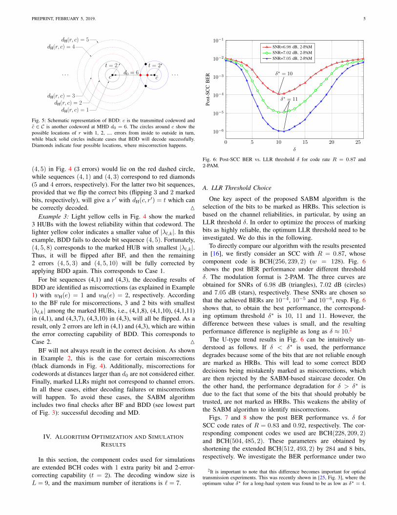
A. LLR Threshold Choice
One key aspect of the proposed SABM algorithm is theselection of the bits to be marked as HRBs. This selection isbased on the channel reliabilities, in particular, by using anLLR threshold δ. In order to optimize the process of markingbits as highly reliable, the optimum LLR threshold need to beinvestigated. We do this in the following.
To directly compare our algorithm with the results presentedin [16], we firstly consider an SCC with R = 0.87, whosecomponent code is BCH(256, 239, 2) (w = 128). Fig. 6shows the post BER performance under different thresholdδ. The modulation format is 2-PAM. The three curves areobtained for SNRs of 6.98 dB (triangles), 7.02 dB (circles)and 7.05 dB (stars), respectively. These SNRs are chosen sothat the achieved BERs are 10−4, 10−5 and 10−6, resp. Fig. 6shows that, to obtain the best performance, the correspond-ing optimum threshold δ∗ is 10, 11 and 11. However, thedifference between these values is small, and the resultingperformance difference is negligible as long as δ ≈ 10.2
The U-type trend results in Fig. 6 can be intuitively un-derstood as follows. If δ < δ∗ is used, the performancedegrades because some of the bits that are not reliable enoughare marked as HRBs. This will lead to some correct BDDdecisions being mistakenly marked as miscorrections, whichare then rejected by the SABM-based staircase decoder. Onthe other hand, the performance degradation for δ > δ∗ isdue to the fact that some of the bits that should probably betrusted, are not marked as HRBs. This weakens the ability ofthe SABM algorithm to identify miscorrections.
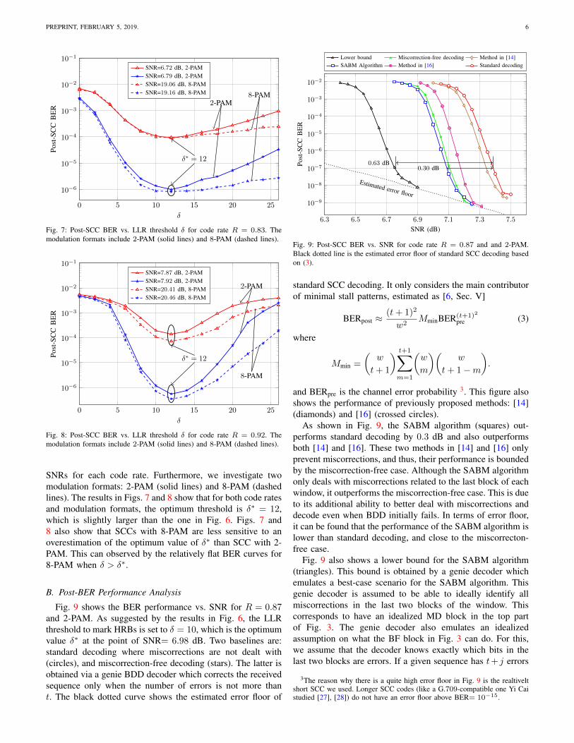
Figs. 7 and 8 show the post BER performance vs. δ forSCC code rates of R = 0.83 and 0.92, respectively. The cor-responding component codes we used are BCH(228, 209, 2)and BCH(504, 485, 2). These parameters are obtained byshortening the extended BCH(512, 493, 2) by 284 and 8 bits,respectively. We investigate the BER performance under two
2It is important to note that this difference becomes important for opticaltransmission experiments. This was recently shown in [25, Fig. 3], where theoptimum value δ∗ for a long-haul system was found to be as low as δ∗ = 4.
PREPRINT, FEBRUARY 5, 2019. 6
0 5 10 15 20 25
10−6
10−5
10−4
10−3
10−2
10−1
δ∗ = 12
2-PAM8-PAM
δ
Post
-SC
CB
ER
SNR=6.72 dB, 2-PAMSNR=6.79 dB, 2-PAMSNR=19.06 dB, 8-PAMSNR=19.16 dB, 8-PAM
Fig. 7: Post-SCC BER vs. LLR threshold δ for code rate R = 0.83. Themodulation formats include 2-PAM (solid lines) and 8-PAM (dashed lines).
0 5 10 15 20 25
10−6
10−5
10−4
10−3
10−2
10−1
δ∗ = 12
2-PAM
8-PAM
δ
Post
-SC
CB
ER
SNR=7.87 dB, 2-PAMSNR=7.92 dB, 2-PAMSNR=20.41 dB, 8-PAMSNR=20.46 dB, 8-PAM
Fig. 8: Post-SCC BER vs. LLR threshold δ for code rate R = 0.92. Themodulation formats include 2-PAM (solid lines) and 8-PAM (dashed lines).
SNRs for each code rate. Furthermore, we investigate twomodulation formats: 2-PAM (solid lines) and 8-PAM (dashedlines). The results in Figs. 7 and 8 show that for both code ratesand modulation formats, the optimum threshold is δ∗ = 12,which is slightly larger than the one in Fig. 6. Figs. 7 and8 also show that SCCs with 8-PAM are less sensitive to anoverestimation of the optimum value of δ∗ than SCC with 2-PAM. This can observed by the relatively flat BER curves for8-PAM when δ > δ∗.
B. Post-BER Performance Analysis
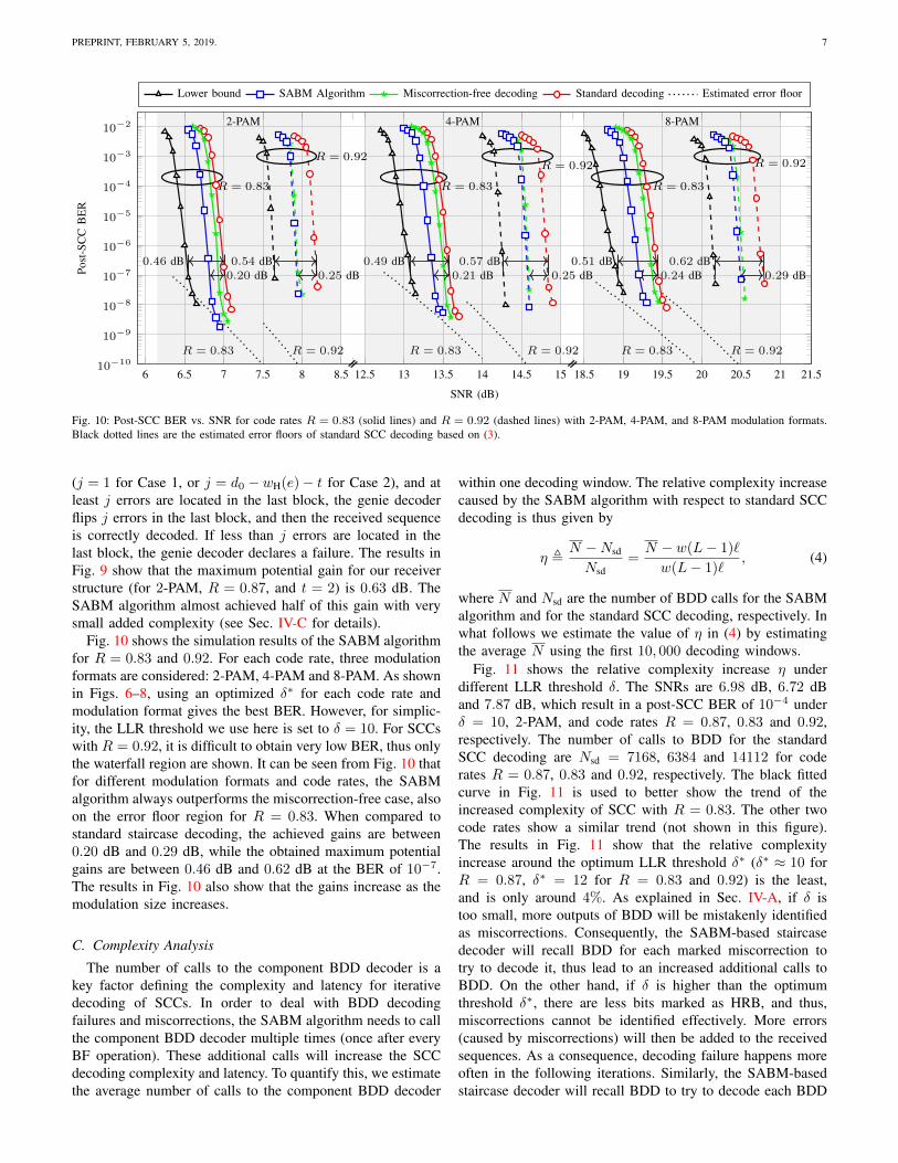
Fig. 9 shows the BER performance vs. SNR for R = 0.87and 2-PAM. As suggested by the results in Fig. 6, the LLRthreshold to mark HRBs is set to δ = 10, which is the optimumvalue δ∗ at the point of SNR= 6.98 dB. Two baselines are:standard decoding where miscorrections are not dealt with(circles), and miscorrection-free decoding (stars). The latter isobtained via a genie BDD decoder which corrects the receivedsequence only when the number of errors is not more thant. The black dotted curve shows the estimated error floor of
6.3 6.5 6.7 6.9 7.1 7.3 7.5
10−9
10−8
10−7
10−6
10−5
10−4
10−3
10−2
Estimated error floor
0.30 dB0.63 dB
SNR (dB)
Post
-SC
CB
ER
Lower bound Miscorrection-free decoding Method in [14]SABM Algorithm Method in [16] Standard decoding
Fig. 9: Post-SCC BER vs. SNR for code rate R = 0.87 and and 2-PAM.Black dotted line is the estimated error floor of standard SCC decoding basedon (3).
standard SCC decoding. It only considers the main contributorof minimal stall patterns, estimated as [6, Sec. V]
BERpost ≈(t+ 1)2
w2MminBER(t+1)2
pre (3)
where
Mmin =
(w
t+ 1
) t+1∑m=1
(w
m
)(w
t+ 1−m
).
and BERpre is the channel error probability 3. This figure alsoshows the performance of previously proposed methods: [14](diamonds) and [16] (crossed circles).
As shown in Fig. 9, the SABM algorithm (squares) out-performs standard decoding by 0.3 dB and also outperformsboth [14] and [16]. These two methods in [14] and [16] onlyprevent miscorrections, and thus, their performance is boundedby the miscorrection-free case. Although the SABM algorithmonly deals with miscorrections related to the last block of eachwindow, it outperforms the miscorrection-free case. This is dueto its additional ability to better deal with miscorrections anddecode even when BDD initially fails. In terms of error floor,it can be found that the performance of the SABM algorithm islower than standard decoding, and close to the miscorrecton-free case.
Fig. 9 also shows a lower bound for the SABM algorithm(triangles). This bound is obtained by a genie decoder whichemulates a best-case scenario for the SABM algorithm. Thisgenie decoder is assumed to be able to ideally identify allmiscorrections in the last two blocks of the window. Thiscorresponds to have an idealized MD block in the top partof Fig. 3. The genie decoder also emulates an idealizedassumption on what the BF block in Fig. 3 can do. For this,we assume that the decoder knows exactly which bits in thelast two blocks are errors. If a given sequence has t+ j errors
3The reason why there is a quite high error floor in Fig. 9 is the realtiveltshort SCC we used. Longer SCC codes (like a G.709-compatible one Yi Caistudied [27], [28]) do not have an error floor above BER= 10−15.
PREPRINT, FEBRUARY 5, 2019. 7
6 6.5 7 7.5 8 8.5 12.5 13 13.5 14 14.5 15 18.5 19 19.5 20 20.5 21 21.510−10
10−9
10−8
10−7
10−6
10−5
10−4
10−3
10−2
//// ////
0.20 dB0.46 dB
R = 0.83
0.25 dB0.54 dB
R = 0.92
0.21 dB0.49 dB
R = 0.83
0.25 dB0.57 dB
R = 0.92
0.24 dB0.51 dB
R = 0.83
0.29 dB0.62 dB
R = 0.92
2-PAM 4-PAM 8-PAM
R = 0.83
R = 0.92
R = 0.83
R = 0.92
R = 0.83
R = 0.92
SNR (dB)
Post
-SC
CB
ER
Lower bound SABM Algorithm Miscorrection-free decoding Standard decoding Estimated error floor
Fig. 10: Post-SCC BER vs. SNR for code rates R = 0.83 (solid lines) and R = 0.92 (dashed lines) with 2-PAM, 4-PAM, and 8-PAM modulation formats.Black dotted lines are the estimated error floors of standard SCC decoding based on (3).
(j = 1 for Case 1, or j = d0 −wH(e)− t for Case 2), and atleast j errors are located in the last block, the genie decoderflips j errors in the last block, and then the received sequenceis correctly decoded. If less than j errors are located in thelast block, the genie decoder declares a failure. The results inFig. 9 show that the maximum potential gain for our receiverstructure (for 2-PAM, R = 0.87, and t = 2) is 0.63 dB. TheSABM algorithm almost achieved half of this gain with verysmall added complexity (see Sec. IV-C for details).
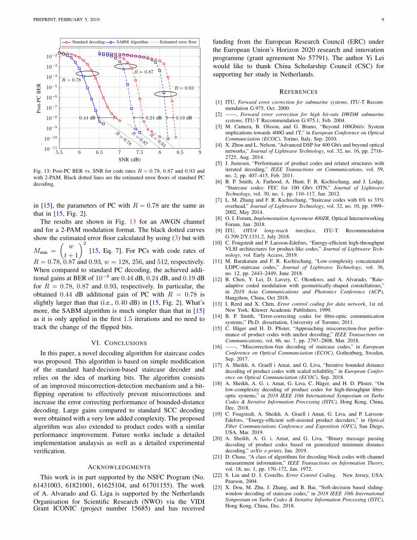
Fig. 10 shows the simulation results of the SABM algorithmfor R = 0.83 and 0.92. For each code rate, three modulationformats are considered: 2-PAM, 4-PAM and 8-PAM. As shownin Figs. 6–8, using an optimized δ∗ for each code rate andmodulation format gives the best BER. However, for simplic-ity, the LLR threshold we use here is set to δ = 10. For SCCswith R = 0.92, it is difficult to obtain very low BER, thus onlythe waterfall region are shown. It can be seen from Fig. 10 thatfor different modulation formats and code rates, the SABMalgorithm always outperforms the miscorrection-free case, alsoon the error floor region for R = 0.83. When compared tostandard staircase decoding, the achieved gains are between0.20 dB and 0.29 dB, while the obtained maximum potentialgains are between 0.46 dB and 0.62 dB at the BER of 10−7.The results in Fig. 10 also show that the gains increase as themodulation size increases.
C. Complexity Analysis
The number of calls to the component BDD decoder is akey factor defining the complexity and latency for iterativedecoding of SCCs. In order to deal with BDD decodingfailures and miscorrections, the SABM algorithm needs to callthe component BDD decoder multiple times (once after everyBF operation). These additional calls will increase the SCCdecoding complexity and latency. To quantify this, we estimatethe average number of calls to the component BDD decoder
within one decoding window. The relative complexity increasecaused by the SABM algorithm with respect to standard SCCdecoding is thus given by
η ,N −Nsd
Nsd=N − w(L− 1)`
w(L− 1)`, (4)
where N and Nsd are the number of BDD calls for the SABMalgorithm and for the standard SCC decoding, respectively. Inwhat follows we estimate the value of η in (4) by estimatingthe average N using the first 10, 000 decoding windows.
Fig. 11 shows the relative complexity increase η underdifferent LLR threshold δ. The SNRs are 6.98 dB, 6.72 dBand 7.87 dB, which result in a post-SCC BER of 10−4 underδ = 10, 2-PAM, and code rates R = 0.87, 0.83 and 0.92,respectively. The number of calls to BDD for the standardSCC decoding are Nsd = 7168, 6384 and 14112 for coderates R = 0.87, 0.83 and 0.92, respectively. The black fittedcurve in Fig. 11 is used to better show the trend of theincreased complexity of SCC with R = 0.83. The other twocode rates show a similar trend (not shown in this figure).The results in Fig. 11 show that the relative complexityincrease around the optimum LLR threshold δ∗ (δ∗ ≈ 10 forR = 0.87, δ∗ = 12 for R = 0.83 and 0.92) is the least,and is only around 4%. As explained in Sec. IV-A, if δ istoo small, more outputs of BDD will be mistakenly identifiedas miscorrections. Consequently, the SABM-based staircasedecoder will recall BDD for each marked miscorrection totry to decode it, thus lead to an increased additional calls toBDD. On the other hand, if δ is higher than the optimumthreshold δ∗, there are less bits marked as HRB, and thus,miscorrections cannot be identified effectively. More errors(caused by miscorrections) will then be added to the receivedsequences. As a consequence, decoding failure happens moreoften in the following iterations. Similarly, the SABM-basedstaircase decoder will recall BDD to try to decode each BDD

PREPRINT, FEBRUARY 5, 2019. 8
0 5 10 15 20
0
5
10
15
δ
rela
tive
com
plex
ityin
crea
seη
(%)
R = 0.87
R = 0.83
R = 0.92
Fig. 11: The relative complexity increase η vs. δ with L = 9, ` = 7 and2-PAM. The SNRs are 6.98 dB, 6.72 dB and 7.87 dB for R = 0.87, 0.83
and 0.92, respectively.
decoding failure. Therefore, the complexity increases slightlyin this case too.
Fig. 12 shows the relative complexity increase η of theSABM algorithm under different post-SCC BER. Similarlyto Fig. 11, the black fitted curve is used to better show thetrend of the increased complexity of SCC with R = 0.83. TheLLR threshold used was δ = 10. When the SNR increases,there are less errors in the received sequence and most ofthe time BDD can deal with them successfully. Therefore,the case of decoding failure or miscorrection happens lessfrequently, leading to a decreased additional calls to BDDin the SABM algorithm. This effect is shown in Fig. 12,where the relative complexity increase reduces as the channelcondition improves. In the asymptotic case (SNR tendingto infinity), the total number of BDD calls in the SABMalgorithm will approach that of the standard SCC decoding,and thus, η → 0.
V. EXTENSION TO PRODUCT CODES
A product code is a set of square arrays of size nc × nc,constructed in such a way that every row or column is anallowed codeword in some component (block) code (nc, kc, t)[29]. Multiple algorithms have been recently proposed toimprove the decoding performance of PCs while keeping amanageable decoding complexity, as in e.g. [5], [15], [18],[30]–[33]. The algorithm we introduced in this paper can alsobe used, with slight modifications, to improve conventionaldecoding of PCs. In this section, first we show how to modifythe SABM algorithm presented in Sec. III to suit PCs, andsecond we illustrate the gains achieved with this improvedapproach.
A. Modification to the SABM Algorithm for PC Decoding
In the SCC case, both MD and BF are applied only tothe last block in the decoding window exploiting the channel
10−3 10−4 10−6
0
2
4
6
8
10
Post-SCC BER
rela
tive
com
plex
ityin
crea
seη
(%)
R = 0.87
R = 0.83
R = 0.92
Fig. 12: The relative complexity increase η vs. post-BER with δ = 10,L = 9, ` = 7 and 2-PAM.
reliabilities (LLRs). This is justified by the fact that the lastblock contains less reliable bits as no previous decodingiterations were perfomed on it. Differently from SCCs, in thePC case, row and column decoding are performed iterativelywithin the same block. As a result, no bits within each blockcan be regarded as more or less reliable than others, andconflicts between column and row decoding are likely to arise.Thus, one may expect to obtain gains only when MD and BFis performed within the first decoding iterations.
In particular, we have analyzed the performance of ouralgorithm and found it needs to be modified as follows. MDand BF operations should only be performed within the firstdecoding iteration and the first half of the second iteration(row decoding). Extending beyond the second iteration wasobserved to degrade the decoding performance, hypotheticallydue to conflicts between row and column decodings. Furthe-more, the BF is only adopted in case of decoding failure (HUBflipping) and not in the case of miscorrection. As for the rowdecoding operated in the first iteration, MD is only operatedbased on the marked HRBs, since no previous information onthe codeword syndromes is available from the decoder. Fromthe first column decoding onwards MD is based on both bitmarking or syndrome information. The reliability threshold tomark the bits was also optimized for the PC case and theoptimal value was found to be identical to the case of SCC,δ = δ∗ = 10.
B. Post-BER Performance Analysis
We consider 3 different PCs based on 1-bit extended BCHcodes as component codes with the following parameters(128, 113, 2), (256, 239, 2), and (512, 493, 2). These param-eters result in a 128 × 128, 256 × 256, and 512 × 512 PCcode arrays with overall code rate R = 0.78, 0.87 and 0.93,respectively. In order to compare with the algorithm proposed
PREPRINT, FEBRUARY 5, 2019. 9
5.5 6 6.5 7 7.5 8 8.5 910−11
10−10
10−9
10−8
10−7
10−6
10−5
10−4
10−3
10−2
0.44 dB 0.24 dB 0.19 dB
R = 0.78
R=0.78
R = 0.87
R=0.87
R = 0.93
R=0.93
R = 0.78
R = 0.87
R = 0.93R = 0.78
R = 0.87
R = 0.93
SNR (dB)
Post
-PC
BE
RStandard decoding SABM Algorithm Estimated error floor
Fig. 13: Post-PC BER vs. SNR for code rates R = 0.78, 0.87 and 0.93 andwith 2-PAM. Black dotted lines are the estimated error floors of standard PCdecoding.
in [15], the parameters of PC with R = 0.78 are the same asthat in [15, Fig. 2].
The results are shown in Fig. 13 for an AWGN channeland for a 2-PAM modulation format. The black dotted curvesshow the estimated error floor calculated by using (3) but with
Mmin =
(w
t+ 1
)2
[15, Eq. 7]. For PCs with code rates of
R = 0.78, 0.87 and 0.93, w = 128, 256, and 512, respectively.When compared to standard PC decoding, the achieved addi-tional gains at BER of 10−8 are 0.44 dB, 0.24 dB, and 0.19 dBfor R = 0.78, 0.87 and 0.93, respectively. In particular, theobtained 0.44 dB additional gain of PC with R = 0.78 isslightly larger than that (i.e., 0.40 dB) in [15, Fig. 2]. What’smore, the SABM algorithm is much simpler than that in [15]as it is only applied in the first 1.5 iterations and no need totrack the change of the flipped bits.
VI. CONCLUSIONS
In this paper, a novel decoding algorithm for staircase codeswas proposed. This algorithm is based on simple modificationof the standard hard-decision-based staircase decoder andrelies on the idea of marking bits. The algorithm consistsof an improved miscorrection-detection mechanism and a bit-flipping operation to effectively prevent miscorrections andincrease the error correcting performance of bounded-distancedecoding. Large gains compared to standard SCC decodingwere obtained with a very low added complexity. The proposedalgorithm was also extended to product codes with a similarperformance improvement. Future works include a detailedimplementation analaysis as well as a detailed experimentalverification.
ACKNOWLEDGMENTS
This work is in part supported by the NSFC Program (No.61431003, 61821001, 61625104, and 61701155). The workof A. Alvarado and G. Liga is supported by the NetherlandsOrganisation for Scientific Research (NWO) via the VIDIGrant ICONIC (project number 15685) and has received
funding from the European Research Council (ERC) underthe European Union’s Horizon 2020 research and innovationprogramme (grant agreement No 57791). The author Yi Leiwould like to thank China Scholarship Council (CSC) forsupporting her study in Netherlands.
REFERENCES
[1] ITU, Forward error correction for submarine systems, ITU-T Recom-mendation G.975, Oct. 2000.
[2] ——, Forward error correction for high bit-rate DWDM submarinesystems, ITU-T Recommendation G.975.1, Feb. 2004.
[3] M. Camera, B. Olsson, and G. Bruno, “Beyond 100Gbit/s: Systemimplications towards 400G and 1T,” in European Conference on OpticalCommunciation (ECOC), Torino, Italy, Sep. 2010.
[4] X. Zhou and L. Nelson, “Advanced DSP for 400 Gb/s and beyond opticalnetworks,” Journal of Lightwave Technology, vol. 32, no. 16, pp. 2716–2725, Aug. 2014.
[5] J. Justesen, “Performance of product codes and related structures withiterated decoding,” IEEE Transactions on Communications, vol. 59,no. 2, pp. 407–415, Feb. 2011.
[6] B. P. Smith, A. Farhood, A. Hunt, F. R. Kschischang, and J. Lodge,“Staircase codes: FEC for 100 Gb/s OTN,” Journal of LightwaveTechnology, vol. 30, no. 1, pp. 110–117, Jan. 2012.
[7] L. M. Zhang and F. R. Kschischang, “Staircase codes with 6% to 33%overhead,” Journal of Lightwave Technology, vol. 32, no. 10, pp. 1999–2002, May 2014.
[8] O. I. Forum, Implementation Agreement 400ZR, Optical InternetworkingForum, Jan. 2018.
[9] ITU, OTU4 long-reach interface, ITU-T RecommendationG.709.2/Y.1331.2, July 2018.
[10] C. Fougstedt and P. Larsson-Edefors, “Energy-efficient high-throughputVLSI architectures for product-like codes,” Journal of Lightwave Tech-nology, vol. Early Access, 2019.
[11] M. Barakatain and F. R. Kschischang, “Low-complexity concatenatedLDPC-staircase codes,” Journal of Lightwave Technology, vol. 36,no. 12, pp. 2443–2449, June 2018.
[12] B. Chen, Y. Lei, D. Lavery, C. Okonkwo, and A. Alvarado, “Rate-adaptive coded modulation with geometrically-shaped constellations,”in 2018 Asia Communications and Photonics Conference (ACP),Hangzhou, China, Oct 2018.
[13] I. Reed and X. Chen, Error control coding for data network, 1st ed.New York: Kluwer Academic Publishers, 1999.
[14] B. P. Smith, “Error-correcting codes for fibre-optic communicationsystems,” Ph.D. dissertation, University of Toronto, 2011.
[15] C. Hager and H. D. Pfister, “Approaching miscorrection-free perfor-mance of product codes with anchor decoding,” IEEE Transactions onCommunications, vol. 66, no. 7, pp. 2797–2808, Mar. 2018.
[16] ——, “Miscorrection-free decoding of staircase codes,” in EuropeanConference on Optical Communciation (ECOC), Gothenburg, Sweden,Sep. 2017.
[17] A. Sheikh, A. Graell i Amat, and G. Liva, “Iterative bounded distancedecoding of product codes with scaled reliability,” in European Confer-ence on Optical Communciation (ECOC), Sep. 2018.
[18] A. Sheikh, A. G. i. Amat, G. Liva, C. Hager, and H. D. Pfister, “Onlow-complexity decoding of product codes for high-throughput fiber-optic systems,” in 2018 IEEE 10th International Symposium on TurboCodes & Iterative Information Processing (ISTC), Hong Kong, China,Dec. 2018.
[19] C. Fougstedt, A. Sheikh, A. Graell i Amat, G. Liva, and P. Larsson-Edefors, “Energy-efficient soft-assisted product decoders,” in OpticalFiber Communciations Conference and Exposition (OFC), San Diego,USA, Mar. 2019.
[20] A. Sheikh, A. G. i. Amat, and G. Liva, “Binary message passingdecoding of product codes based on generalized minimum distancedecoding,” arXiv e-prints, Jan. 2019.
[21] D. Chase, “A class of algorithms for decoding block codes with channelmeasurement information,” IEEE Transactions on Information Theory,vol. 18, no. 1, pp. 170–172, Jan. 1972.
[22] S. Lin and D. J. Costello, Error Control Coding. New Jersey, USA:Pearson, 2004.
[23] X. Dou, M. Zhu, J. Zhang, and B. Bai, “Soft-decision based sliding-window decoding of staircase codes,” in 2018 IEEE 10th InternationalSymposium on Turbo Codes & Iterative Information Processing (ISTC),Hong Kong, China, Dec. 2018.
PREPRINT, FEBRUARY 5, 2019. 10
[24] Y. Lei, A. Alvarado, B. Chen, X. Deng, Z. Cao, J. Li, and K. Xu,“Decoding staircase codes with marked bits,” in 2018 IEEE 10th Inter-national Symposium on Turbo Codes & Iterative Information Processing(ISTC), Hong Kong, China, Dec. 2018.
[25] B. Chen, Y. Lei, S. van der Heide, J. van Weerdenburg, A. Alvarado,and C. Okonkwo, “First experimental verification of improved decodingof staircase codes using marked bits,” in Optical Fiber CommunciationsConference and Exposition (OFC), San Diego, USA, Mar. 2019.
[26] L. Szczecinski and A. Alvarado, Bit-Interleaved Coded Modulation:Fundamentals, Analysis, and Design. Chichester, UK: Wiley, 2015.
[27] Y. Cai, W. Wang, W. Qian, J. Xing, K. Tao, J. Yin, S. Zhang, M. Lei,E. Sun, K. Y. an Hungchang Chien, Q. Liao, and H. Chen, “FPGAinvestigation on error-floor performance of a concatenated staircase andhamming code for 400G-ZR forward error correction,” in Optical FiberCommunciations Conference and Exposition (OFC), San Diego, USA,Mar. 2018.
[28] ——, “FPGA investigation on error-flare performance of a concatenatedstaircase and hamming fec code for 400G inter-data center interconnect,”
Journal of Lightwave Technology, vol. Early Access, Nov. 2018.[29] P. Elias, “Error-free coding,” Transactions of the IRE Professional Group
on Information Theory, vol. 4, no. 4, pp. 29–37, Sep. 1954.[30] T. Mittelholzer, T. Parnell, N. Papandreou, and H. Pozidis, “Improving
the error-floor performance of binary half-product codes,” in 2016International Symposium on Information Theory and Its Applications(ISITA), Oct 2016, pp. 295–299.
[31] C. Condo, F. Leduc-Primeau, G. Sarkis, P. Giard, and W. J. Gross,“Stall pattern avoidance in polynomial product codes,” in 2016 IEEEGlobal Conference on Signal and Information Processing (GlobalSIP),Dec 2016, pp. 699–702.
[32] M. J. S. Sridharan and T. Coe, “Product code based forward errorcorrection system,” Patent US 6,810,499 B2, 13, 2003. [Online].Available: http://www.patentlens.net/patentlens/...
[33] J. Justesen and T. Hoholdt, “Analysis of iterated hard decision decodingof product codes with reed-solomon component codes,” in 2007 IEEEInformation Theory Workshop, Sep. 2007, pp. 174–177.