Embed Size (px)
Citation preview
in: Proc. 9th European Conference on Industrial Furnaces and Boilers (INFUB), Estoril, Portugal, 2011
1 of 13
IMPROVEMENT OF GAS–SOLID INTERACTION IN DUAL CIRCULATING FLUIDIZED BED SYSTEMS
Johannes C. Schmid,* Tobias Pröll, Christoph Pfeifer, Hermann Hofbauer
Vienna University of Technology, Institute of Chemical Engineering
Getreidemarkt 9, 1060 Vienna, Austria *Corresponding author, email: [email protected], phone: +43 1 58801 166385
ABSTRACT Dual fluidized bed systems are increasingly used or investigated for energy conversion technologies such as steam gasification, sorption-enhanced reforming, and chemical looping combustion. Intensive gas–solids contact is required for these processes. Pilot plant tests have been conducted to determine the effect of fluidization regime on gas phase conversion. Based on a previous design proposal comprising two interconnected circulating fluidized bed (CFB) reactors, the addition of flow obstacles is proposed and investigated to significantly increase gas–solids contact. The solids are entrained from one CFB (primary reactor) and directed via a fluidized loop seal to the upper section of the other CFB (secondary reactor). The secondary reactor features circulation of solids within itself and the solids move back to the primary reactor through a fluidized loop seal connecting the bottom of the two reactors. The secondary reactor is divided into zones with improved gas–solid interaction using flow obstacles at defined height intervals. If the fluidizing velocity in the secondary CFB is low enough to avoid high solids entrainment at the top, the bulk of solids will exhibit a net downward movement. Solid fuel can be fed into the lower part up to the middle of the secondary CFB. Due to the dispersed downward movement of the solids, no volatiles are produced in the upper part and the problems of insufficient gas phase conversion are avoided. Further, the proposed design implies conditions where size classification effects take place, which potentially allows selective ash removal. Three different cold flow models have been equipped with flow obstacles and the first results show the fluid dynamic feasibility of the proposed concept. Keywords: fluidization, circulating fluidized beds, fluidized bed systems,
gas–solid reactor, gasification, reforming, chemical looping
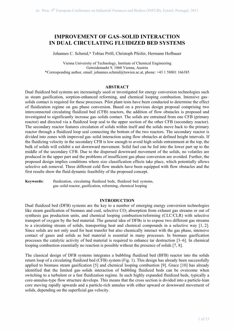
INTRODUCTION Dual fluidized bed (DFB) systems are the key to a number of emerging energy conversion technologies like steam gasification of biomass and coal, selective CO2 absorption from exhaust gas streams or out of synthesis gas production units, and chemical looping combustion/reforming (CLC/CLR) with selective transport of oxygen by the bed material. The general idea of DFBs is to expose two different gas streams to a circulating stream of solids, transporting heat and chemical compounds in a selective way [1, 2]. Since solids are not only used for heat transfer but also chemically interact with the gas phase, intensive contact of gases and solids as bed material is essential in many processes. In biomass gasification processes the catalytic activity of bed material is required to enhance tar destruction [3–6]. In chemical looping combustion essentially no reaction is possible without the presence of solids [7, 8]. The classical design of DFB systems integrates a bubbling fluidized bed (BFB) reactor into the solids return loop of a circulating fluidized bed (CFB) system (Fig. 1). This design has already been successfully applied to biomass steam gasification [5] and chemical looping combustion [9]. Grace [10] has already identified that the limited gas–solids interaction of bubbling fluidized beds can be overcome when switching to a turbulent or a fast fluidization regime. In such highly expanded fluidized beds, typically a core-annulus-type flow structure develops. This means that the cross section is divided into a particle-lean core moving rapidly upwards and a particle-rich annulus with either upward or downward movement of solids, depending on the superficial gas velocity.
2 of 13
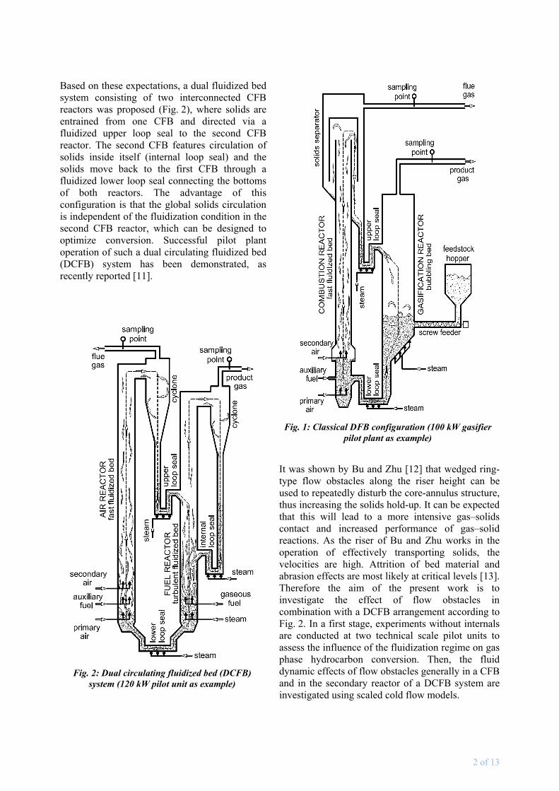
Based on these expectations, a dual fluidized bed system consisting of two interconnected CFB reactors was proposed (Fig. 2), where solids are entrained from one CFB and directed via a fluidized upper loop seal to the second CFB reactor. The second CFB features circulation of solids inside itself (internal loop seal) and the solids move back to the first CFB through a fluidized lower loop seal connecting the bottoms of both reactors. The advantage of this configuration is that the global solids circulation is independent of the fluidization condition in the second CFB reactor, which can be designed to optimize conversion. Successful pilot plant operation of such a dual circulating fluidized bed (DCFB) system has been demonstrated, as recently reported [11].
It was shown by Bu and Zhu [12] that wedged ring-type flow obstacles along the riser height can be used to repeatedly disturb the core-annulus structure, thus increasing the solids hold-up. It can be expected that this will lead to a more intensive gas–solids contact and increased performance of gas–solid reactions. As the riser of Bu and Zhu works in the operation of effectively transporting solids, the velocities are high. Attrition of bed material and abrasion effects are most likely at critical levels [13]. Therefore the aim of the present work is to investigate the effect of flow obstacles in combination with a DCFB arrangement according to Fig. 2. In a first stage, experiments without internals are conducted at two technical scale pilot units to assess the influence of the fluidization regime on gas phase hydrocarbon conversion. Then, the fluid dynamic effects of flow obstacles generally in a CFB and in the secondary reactor of a DCFB system are investigated using scaled cold flow models.
Fig. 1: Classical DFB configuration (100 kW gasifier pilot plant as example)
Fig. 2: Dual circulating fluidized bed (DCFB) system (120 kW pilot unit as example)
3 of 13
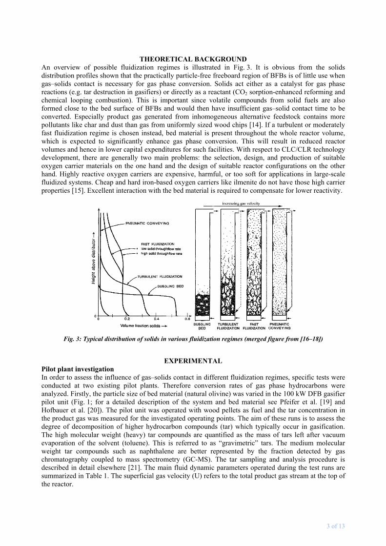
THEORETICAL BACKGROUND An overview of possible fluidization regimes is illustrated in Fig. 3. It is obvious from the solids distribution profiles shown that the practically particle-free freeboard region of BFBs is of little use when gas–solids contact is necessary for gas phase conversion. Solids act either as a catalyst for gas phase reactions (e.g. tar destruction in gasifiers) or directly as a reactant (CO2 sorption-enhanced reforming and chemical looping combustion). This is important since volatile compounds from solid fuels are also formed close to the bed surface of BFBs and would then have insufficient gas–solid contact time to be converted. Especially product gas generated from inhomogeneous alternative feedstock contains more pollutants like char and dust than gas from uniformly sized wood chips [14]. If a turbulent or moderately fast fluidization regime is chosen instead, bed material is present throughout the whole reactor volume, which is expected to significantly enhance gas phase conversion. This will result in reduced reactor volumes and hence in lower capital expenditures for such facilities. With respect to CLC/CLR technology development, there are generally two main problems: the selection, design, and production of suitable oxygen carrier materials on the one hand and the design of suitable reactor configurations on the other hand. Highly reactive oxygen carriers are expensive, harmful, or too soft for applications in large-scale fluidized systems. Cheap and hard iron-based oxygen carriers like ilmenite do not have those high carrier properties [15]. Excellent interaction with the bed material is required to compensate for lower reactivity.
Fig. 3: Typical distribution of solids in various fluidization regimes (merged figure from [16–18])
EXPERIMENTAL
Pilot plant investigation In order to assess the influence of gas–solids contact in different fluidization regimes, specific tests were conducted at two existing pilot plants. Therefore conversion rates of gas phase hydrocarbons were analyzed. Firstly, the particle size of bed material (natural olivine) was varied in the 100 kW DFB gasifier pilot unit (Fig. 1; for a detailed description of the system and bed material see Pfeifer et al. [19] and Hofbauer et al. [20]). The pilot unit was operated with wood pellets as fuel and the tar concentration in the product gas was measured for the investigated operating points. The aim of these runs is to assess the degree of decomposition of higher hydrocarbon compounds (tar) which typically occur in gasification. The high molecular weight (heavy) tar compounds are quantified as the mass of tars left after vacuum evaporation of the solvent (toluene). This is referred to as “gravimetric” tars. The medium molecular weight tar compounds such as naphthalene are better represented by the fraction detected by gas chromatography coupled to mass spectrometry (GC-MS). The tar sampling and analysis procedure is described in detail elsewhere [21]. The main fluid dynamic parameters operated during the test runs are summarized in Table 1. The superficial gas velocity (U) refers to the total product gas stream at the top of the reactor.
4 of 13
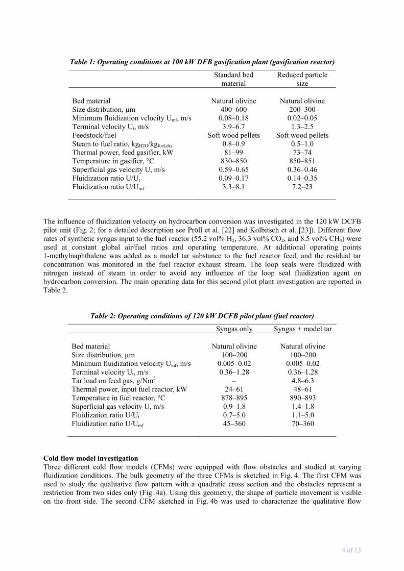
Table 1: Operating conditions at 100 kW DFB gasification plant (gasification reactor)
Standard bed material
Reduced particle size
Bed material
Natural olivine
Natural olivine
Size distribution, µm 400–600 200–300 Minimum fluidization velocity Umf, m/s 0.08–0.18 0.02–0.05 Terminal velocity Ut, m/s 3.9–6.7 1.3–2.5 Feedstock/fuel Soft wood pellets Soft wood pellets Steam to fuel ratio, kgH2O/kgfuel,dry 0.8–0.9 0.5–1.0 Thermal power, feed gasifier, kW 81–99 73–74 Temperature in gasifier, °C 830–850 850–851 Superficial gas velocity U, m/s 0.59–0.65 0.36–0.46 Fluidization ratio U/Ut 0.09–0.17 0.14–0.35 Fluidization ratio U/Umf
3.3–8.1 7.2–23
The influence of fluidization velocity on hydrocarbon conversion was investigated in the 120 kW DCFB pilot unit (Fig. 2; for a detailed description see Pröll et al. [22] and Kolbitsch et al. [23]). Different flow rates of synthetic syngas input to the fuel reactor (55.2 vol% H2, 36.3 vol% CO2, and 8.5 vol% CH4) were used at constant global air/fuel ratios and operating temperature. At additional operating points 1-methylnaphthalene was added as a model tar substance to the fuel reactor feed, and the residual tar concentration was monitored in the fuel reactor exhaust stream. The loop seals were fluidized with nitrogen instead of steam in order to avoid any influence of the loop seal fluidization agent on hydrocarbon conversion. The main operating data for this second pilot plant investigation are reported in Table 2.
Table 2: Operating conditions of 120 kW DCFB pilot plant (fuel reactor)
Syngas only Syngas + model tar Bed material
Natural olivine
Natural olivine
Size distribution, µm 100–200 100–200 Minimum fluidization velocity Umf, m/s 0.005–0.02 0.005–0.02 Terminal velocity Ut, m/s 0.36–1.28 0.36–1.28 Tar load on feed gas, g/Nm3 – 4.8–6.3 Thermal power, input fuel reactor, kW 24–61 48–61 Temperature in fuel reactor, °C 878–895 890–893 Superficial gas velocity U, m/s 0.9–1.8 1.4–1.8 Fluidization ratio U/Ut 0.7–5.0 1.1–5.0 Fluidization ratio U/Umf
45–360 70–360
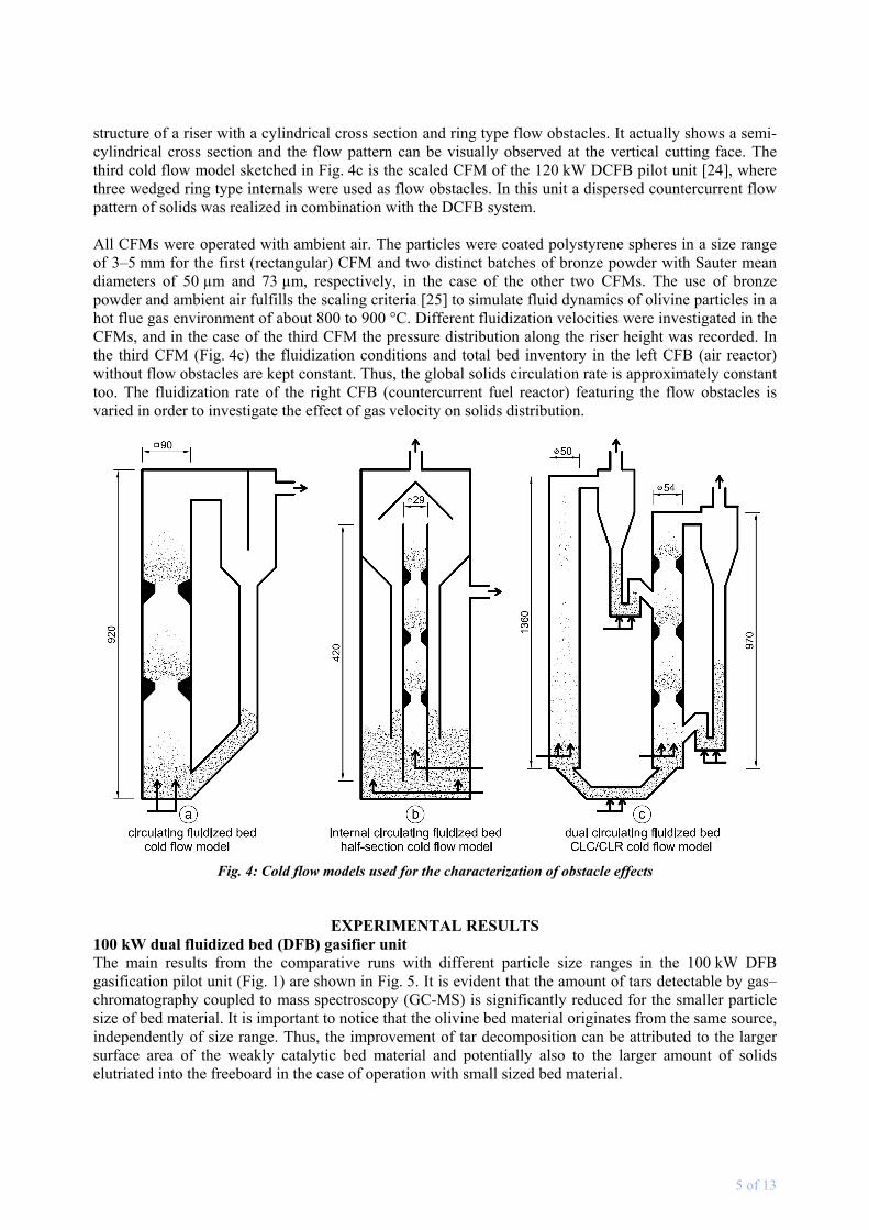
Cold flow model investigation Three different cold flow models (CFMs) were equipped with flow obstacles and studied at varying fluidization conditions. The bulk geometry of the three CFMs is sketched in Fig. 4. The first CFM was used to study the qualitative flow pattern with a quadratic cross section and the obstacles represent a restriction from two sides only (Fig. 4a). Using this geometry, the shape of particle movement is visible on the front side. The second CFM sketched in Fig. 4b was used to characterize the qualitative flow
5 of 13
structure of a riser with a cylindrical cross section and ring type flow obstacles. It actually shows a semi-cylindrical cross section and the flow pattern can be visually observed at the vertical cutting face. The third cold flow model sketched in Fig. 4c is the scaled CFM of the 120 kW DCFB pilot unit [24], where three wedged ring type internals were used as flow obstacles. In this unit a dispersed countercurrent flow pattern of solids was realized in combination with the DCFB system. All CFMs were operated with ambient air. The particles were coated polystyrene spheres in a size range of 3–5 mm for the first (rectangular) CFM and two distinct batches of bronze powder with Sauter mean diameters of 50 µm and 73 µm, respectively, in the case of the other two CFMs. The use of bronze powder and ambient air fulfills the scaling criteria [25] to simulate fluid dynamics of olivine particles in a hot flue gas environment of about 800 to 900 °C. Different fluidization velocities were investigated in the CFMs, and in the case of the third CFM the pressure distribution along the riser height was recorded. In the third CFM (Fig. 4c) the fluidization conditions and total bed inventory in the left CFB (air reactor) without flow obstacles are kept constant. Thus, the global solids circulation rate is approximately constant too. The fluidization rate of the right CFB (countercurrent fuel reactor) featuring the flow obstacles is varied in order to investigate the effect of gas velocity on solids distribution.
Fig. 4: Cold flow models used for the characterization of obstacle effects
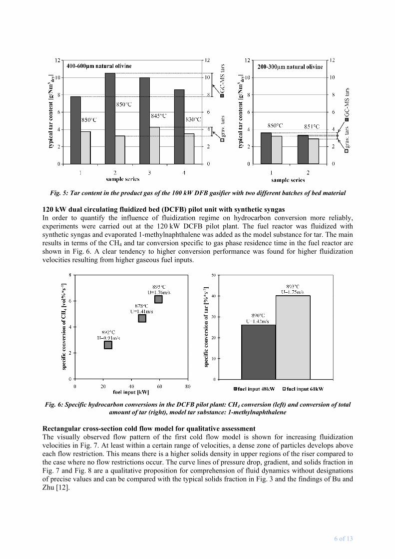
EXPERIMENTAL RESULTS 100 kW dual fluidized bed (DFB) gasifier unit The main results from the comparative runs with different particle size ranges in the 100 kW DFB gasification pilot unit (Fig. 1) are shown in Fig. 5. It is evident that the amount of tars detectable by gas–chromatography coupled to mass spectroscopy (GC-MS) is significantly reduced for the smaller particle size of bed material. It is important to notice that the olivine bed material originates from the same source, independently of size range. Thus, the improvement of tar decomposition can be attributed to the larger surface area of the weakly catalytic bed material and potentially also to the larger amount of solids elutriated into the freeboard in the case of operation with small sized bed material.
6 of 13
Fig. 5: Tar content in the product gas of the 100 kW DFB gasifier with two different batches of bed material 120 kW dual circulating fluidized bed (DCFB) pilot unit with synthetic syngas In order to quantify the influence of fluidization regime on hydrocarbon conversion more reliably, experiments were carried out at the 120 kW DCFB pilot plant. The fuel reactor was fluidized with synthetic syngas and evaporated 1-methylnaphthalene was added as the model substance for tar. The main results in terms of the CH4 and tar conversion specific to gas phase residence time in the fuel reactor are shown in Fig. 6. A clear tendency to higher conversion performance was found for higher fluidization velocities resulting from higher gaseous fuel inputs.
Fig. 6: Specific hydrocarbon conversions in the DCFB pilot plant: CH4 conversion (left) and conversion of total amount of tar (right), model tar substance: 1-methylnaphthalene
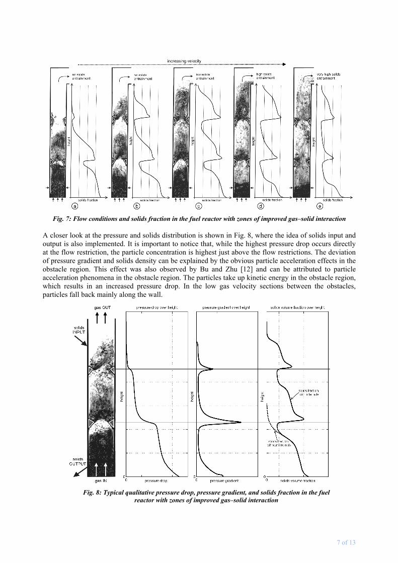
Rectangular cross-section cold flow model for qualitative assessment The visually observed flow pattern of the first cold flow model is shown for increasing fluidization velocities in Fig. 7. At least within a certain range of velocities, a dense zone of particles develops above each flow restriction. This means there is a higher solids density in upper regions of the riser compared to the case where no flow restrictions occur. The curve lines of pressure drop, gradient, and solids fraction in Fig. 7 and Fig. 8 are a qualitative proposition for comprehension of fluid dynamics without designations of precise values and can be compared with the typical solids fraction in Fig. 3 and the findings of Bu and Zhu [12].
7 of 13
Fig. 7: Flow conditions and solids fraction in the fuel reactor with zones of improved gas–solid interaction A closer look at the pressure and solids distribution is shown in Fig. 8, where the idea of solids input and output is also implemented. It is important to notice that, while the highest pressure drop occurs directly at the flow restriction, the particle concentration is highest just above the flow restrictions. The deviation of pressure gradient and solids density can be explained by the obvious particle acceleration effects in the obstacle region. This effect was also observed by Bu and Zhu [12] and can be attributed to particle acceleration phenomena in the obstacle region. The particles take up kinetic energy in the obstacle region, which results in an increased pressure drop. In the low gas velocity sections between the obstacles, particles fall back mainly along the wall.
Fig. 8: Typical qualitative pressure drop, pressure gradient, and solids fraction in the fuel reactor with zones of improved gas–solid interaction
8 of 13
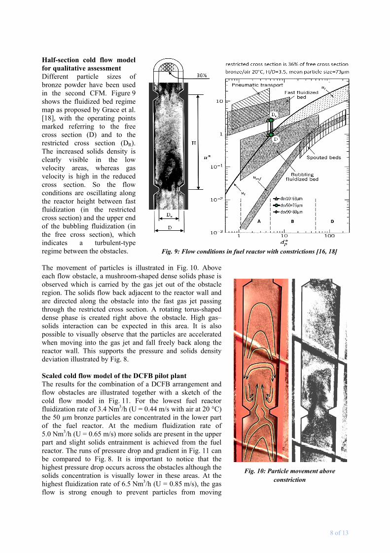
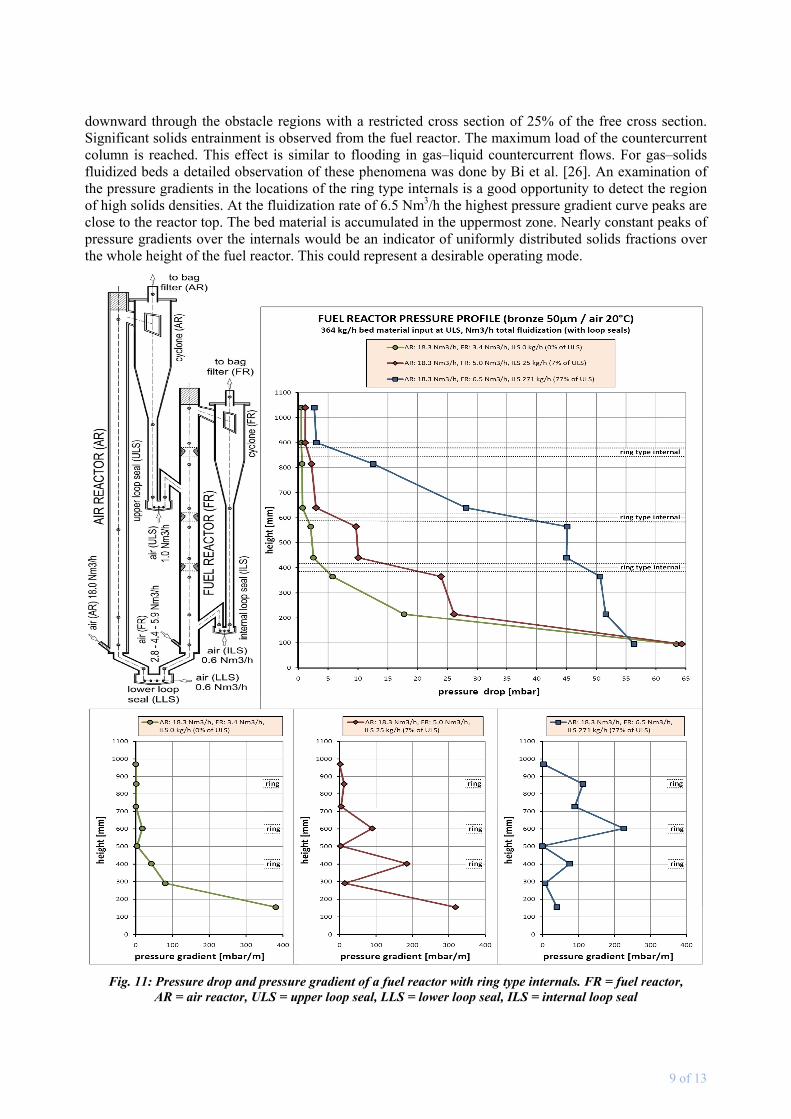
Half-section cold flow model for qualitative assessment Different particle sizes of bronze powder have been used in the second CFM. Figure 9 shows the fluidized bed regime map as proposed by Grace et al. [18], with the operating points marked referring to the free cross section (D) and to the restricted cross section (DR). The increased solids density is clearly visible in the low velocity areas, whereas gas velocity is high in the reduced cross section. So the flow conditions are oscillating along the reactor height between fast fluidization (in the restricted cross section) and the upper end of the bubbling fluidization (in the free cross section), which indicates a turbulent-type regime between the obstacles. The movement of particles is illustrated in Fig. 10. Above each flow obstacle, a mushroom-shaped dense solids phase is observed which is carried by the gas jet out of the obstacle region. The solids flow back adjacent to the reactor wall and are directed along the obstacle into the fast gas jet passing through the restricted cross section. A rotating torus-shaped dense phase is created right above the obstacle. High gas–solids interaction can be expected in this area. It is also possible to visually observe that the particles are accelerated when moving into the gas jet and fall freely back along the reactor wall. This supports the pressure and solids density deviation illustrated by Fig. 8. Scaled cold flow model of the DCFB pilot plant The results for the combination of a DCFB arrangement and flow obstacles are illustrated together with a sketch of the cold flow model in Fig. 11. For the lowest fuel reactor fluidization rate of 3.4 Nm3/h (U = 0.44 m/s with air at 20 °C) the 50 µm bronze particles are concentrated in the lower part of the fuel reactor. At the medium fluidization rate of 5.0 Nm3/h (U = 0.65 m/s) more solids are present in the upper part and slight solids entrainment is achieved from the fuel reactor. The runs of pressure drop and gradient in Fig. 11 can be compared to Fig. 8. It is important to notice that the highest pressure drop occurs across the obstacles although the solids concentration is visually lower in these areas. At the highest fluidization rate of 6.5 Nm3/h (U = 0.85 m/s), the gas flow is strong enough to prevent particles from moving
Fig. 10: Particle movement above constriction
Fig. 9: Flow conditions in fuel reactor with constrictions [16, 18]
9 of 13
downward through the obstacle regions with a restricted cross section of 25% of the free cross section. Significant solids entrainment is observed from the fuel reactor. The maximum load of the countercurrent column is reached. This effect is similar to flooding in gas–liquid countercurrent flows. For gas–solids fluidized beds a detailed observation of these phenomena was done by Bi et al. [26]. An examination of the pressure gradients in the locations of the ring type internals is a good opportunity to detect the region of high solids densities. At the fluidization rate of 6.5 Nm3/h the highest pressure gradient curve peaks are close to the reactor top. The bed material is accumulated in the uppermost zone. Nearly constant peaks of pressure gradients over the internals would be an indicator of uniformly distributed solids fractions over the whole height of the fuel reactor. This could represent a desirable operating mode.
Fig. 11: Pressure drop and pressure gradient of a fuel reactor with ring type internals. FR = fuel reactor,
AR = air reactor, ULS = upper loop seal, LLS = lower loop seal, ILS = internal loop seal
10 of 13
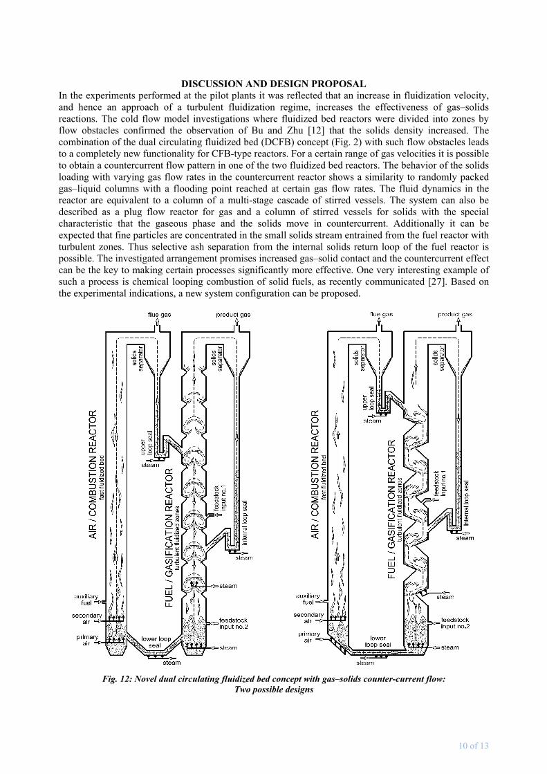
DISCUSSION AND DESIGN PROPOSAL In the experiments performed at the pilot plants it was reflected that an increase in fluidization velocity, and hence an approach of a turbulent fluidization regime, increases the effectiveness of gas–solids reactions. The cold flow model investigations where fluidized bed reactors were divided into zones by flow obstacles confirmed the observation of Bu and Zhu [12] that the solids density increased. The combination of the dual circulating fluidized bed (DCFB) concept (Fig. 2) with such flow obstacles leads to a completely new functionality for CFB-type reactors. For a certain range of gas velocities it is possible to obtain a countercurrent flow pattern in one of the two fluidized bed reactors. The behavior of the solids loading with varying gas flow rates in the countercurrent reactor shows a similarity to randomly packed gas–liquid columns with a flooding point reached at certain gas flow rates. The fluid dynamics in the reactor are equivalent to a column of a multi-stage cascade of stirred vessels. The system can also be described as a plug flow reactor for gas and a column of stirred vessels for solids with the special characteristic that the gaseous phase and the solids move in countercurrent. Additionally it can be expected that fine particles are concentrated in the small solids stream entrained from the fuel reactor with turbulent zones. Thus selective ash separation from the internal solids return loop of the fuel reactor is possible. The investigated arrangement promises increased gas–solid contact and the countercurrent effect can be the key to making certain processes significantly more effective. One very interesting example of such a process is chemical looping combustion of solid fuels, as recently communicated [27]. Based on the experimental indications, a new system configuration can be proposed.
Fig. 12: Novel dual circulating fluidized bed concept with gas–solids counter-current flow: Two possible designs
11 of 13
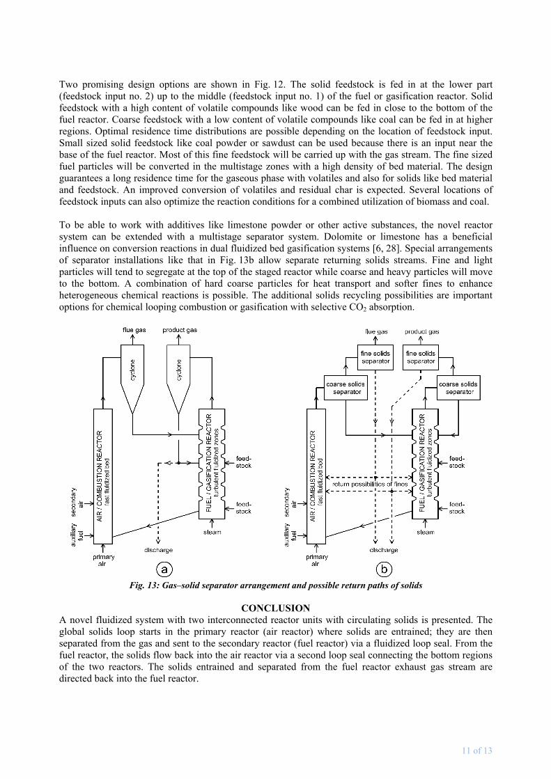
Two promising design options are shown in Fig. 12. The solid feedstock is fed in at the lower part (feedstock input no. 2) up to the middle (feedstock input no. 1) of the fuel or gasification reactor. Solid feedstock with a high content of volatile compounds like wood can be fed in close to the bottom of the fuel reactor. Coarse feedstock with a low content of volatile compounds like coal can be fed in at higher regions. Optimal residence time distributions are possible depending on the location of feedstock input. Small sized solid feedstock like coal powder or sawdust can be used because there is an input near the base of the fuel reactor. Most of this fine feedstock will be carried up with the gas stream. The fine sized fuel particles will be converted in the multistage zones with a high density of bed material. The design guarantees a long residence time for the gaseous phase with volatiles and also for solids like bed material and feedstock. An improved conversion of volatiles and residual char is expected. Several locations of feedstock inputs can also optimize the reaction conditions for a combined utilization of biomass and coal. To be able to work with additives like limestone powder or other active substances, the novel reactor system can be extended with a multistage separator system. Dolomite or limestone has a beneficial influence on conversion reactions in dual fluidized bed gasification systems [6, 28]. Special arrangements of separator installations like that in Fig. 13b allow separate returning solids streams. Fine and light particles will tend to segregate at the top of the staged reactor while coarse and heavy particles will move to the bottom. A combination of hard coarse particles for heat transport and softer fines to enhance heterogeneous chemical reactions is possible. The additional solids recycling possibilities are important options for chemical looping combustion or gasification with selective CO2 absorption.
Fig. 13: Gas–solid separator arrangement and possible return paths of solids
CONCLUSION
A novel fluidized system with two interconnected reactor units with circulating solids is presented. The global solids loop starts in the primary reactor (air reactor) where solids are entrained; they are then separated from the gas and sent to the secondary reactor (fuel reactor) via a fluidized loop seal. From the fuel reactor, the solids flow back into the air reactor via a second loop seal connecting the bottom regions of the two reactors. The solids entrained and separated from the fuel reactor exhaust gas stream are directed back into the fuel reactor.
12 of 13
Pilot scale experiments show that hydrocarbon conversion performance improves with increasing fluidization velocity, probably due to improved gas–solids contact in the turbulent fluidization regime compared to a bubbling regime. Further improvement of gas–solids contact can be achieved by modification of the geometry of the secondary fluidized bed. The reactor is then practically divided into a sequence of sections by necks built out of, for example, refractory. Solids density is high in each section between these necks. It is possible to feed the solids coming from the primary reactor close to the top of the moderately fluidized secondary reactor. Since the solids leave the secondary reactor at the bottom, this allows a countercurrent flow regime of gas and solids in the secondary CFB. The fluid dynamics are equivalent to a column of a multistage cascade of stirred vessels. In addition to that the gas phase and the solids have contrary (countercurrent) movements in this part of the system. Increased gas–solid contact can be expected in the turbulent regime. Examining the aspirated turbulent flow conditions in the fuel reactor and the way in which the two circulating fluidized bed reactors are connected (loop seals), the innovation of the novel design is conspicuous. The observation of flow characteristics with different bed materials and fluidization behaviors with various geometrical conditions will be done in a new cold flow model. It will be the scope of future research to develop concepts for reliable scale-up. The cold flow model will correspond to a pilot plant with 100 to 200 kW of feedstock input, which is currently in the phase of planning with careful attention to scaling relationships for fluidized beds. Important results on the ability to feed different solid fuels, possible operation modes, and abrasion effects will be worked out. Due to the lower gas velocities in turbulent fluidization, the erosion of installations of the plant seems manageable. Based on the cold flow model results it is shown that the improvement is significant and the pressure drop increase is acceptable, especially because the highest pressure drops are in the fuel reactor with steam fluidization. The countercurrent effect can improve conversions in gasification systems and is considered a key feature when solid fuels are to be used directly in chemical looping combustion. The most important conclusion is that the type of internal proposed represents a rather simple geometrical change and thus promises good applicability to refractory-lined units at industrial scale.
ACKNOWLEDGEMENTS Valuable support by Ignacio Diaz, Karl Mayer, Klemens Marx, Stefan Penthor, Carolina Guio, Veronika Wilk, Stefan Koppatz, and Reinhard Jentsch is gratefully acknowledged. This work is part of the projects G-volution and G-volution II under the “New Energies 2020” calls of the Austrian Climate and Energy Fund processed by the Austrian Research Promotion Agency (FFG). The work has been accomplished in cooperation with TECON Engineering GmbH.
REFERENCES
[1] Hofbauer, H., Stoiber, H., Veronik, G., “Gasification of organic material in a novel fluidization bed system”, in: Proc. 1st SCEJ Symp. Fluidization, Tokyo, pp.291–299, 1995
[2] Hofbauer, H., Veronik, G., Fleck, T., Rauch, R., “The FICFB gasification process”, in: Developments in Thermochemical Biomass Conversion, Vol. 2, Banff, pp.1016–1025, 1997
[3] Delgado, J., Aznar, M. P., Corella, J., “Calcined dolomite, magnesite, and calcite for cleaning hot gas from a fluidized bed biomass gasifier with steam: Life and usefulness”, Ind. Eng. Chem. Res. 35, pp.3637–3643, 1996
[4] Corella, J., Aznar, M. P., Gil, J., Caballero, M. A., “Biomass gasification in fluidized bed: where to locate the dolomite to improve gasification”, Energy Fuels 13 (6), pp.1122–1127, 1999
[5] Rauch, R., Hofbauer, H., Bosch, K., Siefert, I., Aichernig, C., Tremmel, H., Voigtlaender, K., Koch, R., Lehner, R., “Steam gasification of biomass at CHP plant Güssing – status of the demonstration plant”, in: Proc. 2nd World Conf. and Technology Exhibition on Biomass for Energy, Industry and Climate Protection, Rome, Italy, 2004
[6] Koppatz, S., Pfeifer, C., Rauch, R., Hofbauer, H., Marquard-Möllenstedt, T., Specht, M., “H2 rich product gas by steam gasification of biomass with in situ CO2 absorption in a dual fluidized bed system of 8 MW fuel input”, Fuel Process. Technol. 90 (7/8), pp.914–921, 2009
13 of 13
[7] Ishida, M., Jin, H. G., “Chemical-looping combustion power generation plant system”, United States Patent, patent number: 5,447,024, filed: Nov. 7, 1994, date of patent: Sept. 5, 1995
[8] Mattisson, T., Lyngfelt, A., “Applications of chemical-looping combustion with capture of CO2”, in: Second Nordic Minisymposium on Carbon Dioxide Capture and Storage, Göteborg, October 26, 2001
[9] Lyngfelt, A., Thunman, H., “Chemical-looping combustion: Design, construction and 100 h of operational experience of a 10 kW prototype”, in: Thomas, D. (Ed.), Carbon Dioxide Capture for Storage in Deep Geologic Formations – Results from the CO2 Capture Project: Vol. 1 – Capture and Separation of Carbon Dioxide from Combustion, Elsevier, London. ISBN 0080445705, 2004
[10] Grace, J. R., “High-velocity fluidized bed reactors”, Chem. Eng. Sci. 45, pp.1953–1966, 1990
[11] Pröll, T., Kolbitsch, P., Bolhàr-Nordenkampf J., Hofbauer, H., "A dual circulating fluidized bed (DCFB) system for chemical looping combustion", in: Proc 2008 AIChE Annual Meeting, Philadelphia, PA, November 16–21, 2008
[12] Bu, J., Zhu, J. X., "Influence of ring-type internals on axial pressure distribution in circulating fluidized bed", Can. J. Chem. Eng. 77(1), pp.26–34, 1999
[13] Werther, J., Reppenhagen, J., “Attrition in fluidized beds and pneumatic conveying lines”, in: Wang, W.C. (Ed.), Fluidization Solids Handling and Processing, Noyes Publications, p. 435 ff, 1999
[14] Wilk, V., Kitzler, H., Koppatz, S., Pfeifer, C., Hofbauer, H., "Gasification of residues and waste wood in a dual fluidised bed steam gasifier", in: Proc. Int. Conf. Polygeneration Stategies, Leipzig (ICPS 10), Deutschland, September 7–9, 2010
[15] Lyngfelt, A., Johansson, M. and Mattisson, T., “Chemical-looping combustion – status of development”, in: 9th Int. Conf. Circulating Fluidized Beds, May 13–16, Hamburg, 2008
[16] Kunii, D., Levenspiel, O., “Circulating fluidized-bed reactors”, Chem. Eng. Sci. 52 (15), pp.2471–2482, 1996
[17] Lim, K. S., Zhu, J. X., Grace, J. R., “Hydrodynamics of gas–solid fluidization”, Int. J. Multiphase Flow 2l (Suppl.), pp.141–193, 1995
[18] Grace, J. R., “Contacting modes and behaviour classification of gas–solid and other two-phase suspensions” Can. J. Chem. Eng. 64, pp.353–363, 1986
[19] Pfeifer, C., Puchner, B., Hofbauer, H., "Comparison of dual fluidized bed steam gasification of biomass with and without selective transport of CO2", Chem. Eng. Sci. J. 64, pp.5073–5083, 2009
[20] Hofbauer, H., Rauch, R., Loeffler, G., Kaiser, S., Fercher, E., Tremmel, H., “Six years experience with the FICFB-gasification process”, in: 12th European Conf. and Technology Exhibition on Biomass for Energy, Industry and Climate Protection, Amsterdam, The Netherlands, Jun 17–21, 2002
[21] Wolfesberger, U., Aigner, I., Hofbauer H., “Content and composition in producer gas of fluidized bed gasification of wood – Influence of temperature and pressure”, Environ. Prog Sustain. Energy 28 (3), pp.372–379, 2009
[22] Pröll, T., Kolbitsch, P., Bolhàr-Nordenkampf, J., Hofbauer, H., "A novel dual circulating fluidized bed system for chemical looping processes", AIChE J. 55 (12), pp. 3255–3266, 2009
[23] Kolbitsch, P., Pröll, T., Bolhàr-Nordenkampf, J., Hofbauer, H., “Design of a chemical looping combustor using a dual circulating fluidized bed (DCFB) reactor system”, Chem. Eng. Technol. 32 (3), pp.398–403, 2009
[24] Pröll, T., Rupanovits, K., Kolbitsch, P., Bolhàr-Nordenkampf, J., Hofbauer, H., "Cold flow model study on a dual circulating fluidized bed system for chemical looping processes", Chem. Eng. Technol. 32(3), pp.418–424, 2009
[25] Glicksman, L. R., Hyre, M. and Woloshun, K., “Simplified scaling relationships for fluidized beds,” Powder Technol. 77, pp.177–199, 1993
[26] Bi, H., Cui, H., Grace, J. R., Kern, A., Lim, C. J., Rusnell, D., Song, X., McKnight, C., “Flooding of gas−solids countercurrent flow in fluidized beds”, Ind. Eng. Chem. Res. 43 (18), pp.5611–5619, 2004
[27] Pröll, T., Hofbauer, H., "A dual fluidized bed system for chemical looping combustion of solid fuels", in: Proc. AIChE Annual Meeting 2010, Salt Lake City, Utah, U.S.A., Nov. 7–12, 2010
[28] Pfeifer, C., Koppatz, S., Hofbauer, H., "Catalysts for fluidized bed biomass gasification – Overview on recent developments and applications", in: Proc. Int. Conf. Polygeneration Strategies (ICPS10), Leipzig, Germany, September 7–9, 2010