Embed Size (px)
Citation preview

1. Introduction
Cavitation sometimes causes severe damage in hydraulicmachinery, as severe impact is produced as cavitation bub-bles collapse. However, cavitation impact can also be uti-lized to improve the surface in the same way as shot peen-ing.1–10) As shot are not required, the peening method usingcavitation impact is called “cavitation shotless peen-ing”11–19) or simply “cavitation peening”.20) One of themajor advantages of cavitation shotless peening is that thepeened surface is very smooth compared with a shotpeened one, as there are no collisions between solid materi-als. Cavitation shotless peening can introduce compressiveresidual stress to mitigate stress corrosion cracking or toeliminate fretting fatigue,8,12,14) and enhance the fatiguestrength of metallic materials.11,13,15–19) In order to developcavitation shotless peening for practical applications, it isvery important to enhance the cavitation impact to achievebetter results and shorten the processing time.
In the case of conventional cavitation shotless peening,the cavitation bubbles are produced by injecting a high-speed water jet into a water filled chamber, where the cavi-tation bubbles form in the shear layer around the jet.8–19) Ahigh-speed water jet with cavitation bubbles is called a cav-itating jet. However, in this paper, since the jet is introducedinto a water filled chamber, we call this “a cavitating jet in
water”.In order to treat the surface of metallic materials,
Soyama successfully realized “a cavitating jet in air” by in-jecting a high-speed water jet into a low-speed water jet di-rectly injected into air.21) It was shown that the optimizedcavitating jet in air had better performance than a cavitatingjet in water and even a water jet in air.21,22) However, gearscannot be treated by a cavitating jet in air, as the tops of thegear teeth break the water shield of a low-speed water jetand the cavitating jet becomes a simple air injected waterjet. In the case of a cavitating jet in air, the residual bubblesare swept away after the cavitation bubbles collapse. This isone of reasons why the cavitating jet in air is highly aggres-sive, as the cushion effect from the residual bubbles is ab-sent. The cushion effect causes the cavitation impact to de-crease when air bubbles are injected into the cavitating re-gion, since the shock wave at cavitation is weakened due tothe slow rebound of the cavitation bubbles. Thus, it mightbe possible to enhance the cavitation impact of a cavitatingjet in water, by injecting a low-speed water jet around thecavitating jet to eliminate the residual bubbles which giverise to the cushion effect.
In this paper, in order to demonstrate the improved per-formance of a cavitating jet in water by injecting an associ-ated water jet, stainless steel specimens were treated by thejet and tested using a plate bending fatigue test. The resid-
1577 © 2008 ISIJ
ISIJ International, Vol. 48 (2008), No. 11, pp. 1577–1581
Improvement of the Fatigue Strength of Stainless Steel SUS316Lby a Cavitating Jet with an Associated Water Jet in Water
Hitoshi SOYAMA,1) Yuichi SEKINE2) and Yosuke OYAMA3)
1) Department of Nanomechanics, Tohoku University, Aoba 6-6-01, Aramaki, Aoba-ku, Sendai, Miyagi 980-8579 Japan. E-mail: [email protected] 2) Graduate Student, Department of Nanomechanics, Tohoku University, Aoba6-6-01, Aramaki, Aoba-ku, Sendai, Miyagi 980-8579 Japan. 3) Department of Nanomechanics, Tohoku University, Aoba6-6-01, Aramaki, Aoba-ku, Sendai, Miyagi 980-8579 Japan.
(Received on June 24, 2008; accepted on August 11, 2008 )
Cavitation impact induced by a cavitating jet can be utilized to improve fatigue strength in the same wayas shot peening. The peening method using cavitation impact is known as “cavitation shotless peening”, asshot are not required. For practical purposes, enhancement of the cavitation impact is required in order toget a better peening effect and to shorten the processing time. In the present paper, intensification of thecavitation impact was successfully realized by injecting a low-speed water jet around a cavitating jet inwater, and an improvement in the fatigue strength of stainless steel was demonstrated by subjectingtreated materials to a fatigue test. The fatigue strength of stainless steel was improved by about 28% bycavitation shotless peening compared with a non-peened specimen. In order to clarify the mechanism forsurface enhancement by cavitation shotless peening, the residual stress on the surface was measuredusing an X-ray diffraction method. It was shown that cavitation shotless peening using a cavitating jet withan associated low-speed water jet in water introduced compressive residual stress on the surface of thesteel. Interestingly, it was also found that the full width at half maximum of the X-ray diffraction profile fromthe surface decreased, even though compressive residual stress of about 500 MPa had been introduced bythe cavitation shotless peening.
KEY WORDS: fatigue; strength; stainless steel; surface improvement; peening; cavitation.
ual stress of the specimens was also measured using an X-ray diffraction method to examine the reasons for the im-provement in fatigue strength.
2. Experimental Apparatus and Procedures
Figures 1 and 2 illustrate the cavitating jet apparatus andthe nozzle geometry for cavitation shotless peening using acavitating jet with an associated low-speed water jet inwater. As shown in the Fig. 1, the high-speed water jet ispressurized by a plunger pump and is injected into the low-speed water jet, which is injected into a water filled cham-ber. The low-speed water jet is pressurized by a turbinepump. The residual bubbles rise to the surface and expire,while the test water is recirculated from tank A to tank B.The injection pressures of the high-and low-speed waterjets are measured by pressure transducers. The nozzlethroat diameter of the high-speed water jet dH is 1 mm andthat of the low-speed water jet dL is 50 mm. The standoffdistance is defined as the distance from the nozzle outlet tothe specimen. With the injection pressure of the high-speedwater jet kept constant, the performance of this equipmentvaries with the injection pressure of the low-speed water jetand the standoff distance.23) In the experiments carried outfor this work, the injection pressure of the high-speed waterjet pH was set to 30 MPa. Referring previous work23) inwhich we did erosion tests using a pure aluminum speci-men, the injection pressure of the low-speed water jet pL
was set to 0.04 MPa, the distance between the high- andlow-speed jets sH�sL was set to 30 mm, and the standoffdistance from the low-speed water jet nozzle sL was 30 mm.In the present experiment, it is assumed that the greater themass loss the higher the jet’s performance. Tap water wasused in the cavitating jet loop.
The processing time per unit length tp is defined by thescanning speed v and the number of scans n as follows:
.....................................(1)
In order to investigate the improvement in fatiguestrength achieved, stainless steel Japan Industrial StandardJIS SUS316L was chosen as the test material. The surfacesof specimens were finished by grinding and the shapesformed by milling. Figure 3 shows the shape of the speci-mens used in the plate bending fatigue test. In this test, theload is applied by displacement control and the stress ratio,R, was �1. To treat the surface, the test nozzle was scannedacross the specimen in the width direction. The surfaceroughness was then measured using a roughness meter.
The residual stress sR of the specimen in the longitudi-nal direction was measured using an X-ray diffractionmethod employing an X-ray tube with a Cr target operatedat 30 kV and 8 mA. X-rays from the Kb peak were used.The angle of the solar slit was 1 degree and the slit widthwas 4 mm. The diffractive angle, 2q , was varied from 142.6to 154.4 degree specimen in steps of 0.2 degree and thesample was exposed to X-rays for 8 s in each step. A scin-tillation counter was used as a detector and placed at anglesof y�0, 22.8, 33.2, 42.1, 50.7 degree, where y is the anglebetween the normal to the specimen surface and the normalto the diffractive face. The diffractive plane was the (311)plane of g-Fe, the diffractive angle 2q without strain was148.5 degree and the stress factor for this method was�368.9 MPa/deg. The diffractive angle was determined bya half value width method and the residual stress was calcu-lated by a sin2 y method, i.e., the gradient of the line fromthe five points on the 2q–sin2 y diagram using a leastsquares method.
3. Results
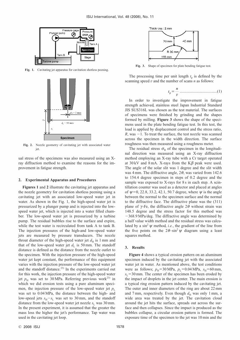
Figure 4 shows a typical erosion pattern on an aluminumspecimen induced by the cavitating jet with the associatedwater jet in water. As mentioned above, the test conditionswere as follows; pH�30 MPa, pL�0.04 MPa, sH�60 mm,sL�30 mm. The center of the specimen has been eroded bythe impact of droplets in the jet center. The main erosion isa typical ring erosion pattern induced by the cavitating jet.The outer and inner diameters of the ring are about 22 mmand 7 mm, respectively. Even though dH was only 1 mm, awide area was treated by the jet. The cavitation cloudaround the jet hits the surface, spreads out across the sur-face and then collapses. Since the impact is produced as thebubbles collapse, a circular erosion pattern is formed. Theexposure time of the specimen to the jet was 10 min and the
tn
p �v
ISIJ International, Vol. 48 (2008), No. 11
1578© 2008 ISIJ
Fig. 2. Nozzle geometry of cavitating jet with associated waterjet.
Fig. 3. Shape of specimen for plate bending fatigue test.Fig. 1. Cavitating jet apparatus for cavitation shotless peening.
mass loss was 249.9 mg, thus the rate of erosion was about25 mg/min. The rate of erosion achieved with a cavitatingjet without an associated water jet in water was 5.0 mg/minand that of a cavitating jet in air was 18.5 mg/min22); thus,the rate of erosion induced by the cavitating jet with an as-sociated water jet in water was greater than both these oth-ers, demonstrating that this is the most powerful of the jetsstudied so far.
Figure 5 illustrates the residual stress of stainless steel asa function of processing time per unit length. The cavitatingjet conditions were the same as in Fig. 4; pH�30 MPa,pL�0.04 MPa, sH�60 mm, sL�30 mm. The residual stressbefore peening by the jet was 160�50 MPa in tension. Itbecame 190�20 MPa in compression at 1 s/mm then satu-rated at about 500 MPa after 8 s/mm. As in the case of acavitating jet without an associated water jet, the compres-sive residual stress introduced saturated at 20 s/mm,23)
showing that the proposed cavitating jet with an associatedwater jet is a more powerful tool for introducing compres-sive residual stress.
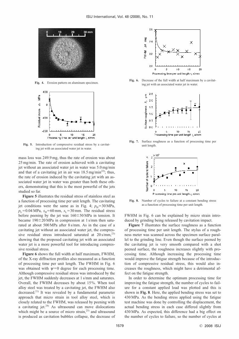
Figure 6 shows the full width at half maximum, FWHM,of the X-ray diffraction profiles also measured as a functionof processing time per unit length. The FWHM in Fig. 6was obtained with y�0 degree for each processing time.Although compressive residual stress was introduced by thejet, the FWHM suddenly decreases at 1 s/mm and saturates.Overall, the FWHM decreases by about 15%. When toolalloy steel was treated by a cavitating jet, the FWHM alsodecreased.21) It was revealed by a fundamental parameterapproach that micro strain in tool alloy steel, which isclosely related to the FWHM, was released by peening witha cavitating jet.24) As ultrasound can move dislocationswhich might be a source of micro strain,25) and ultrasoundis produced as cavitation bubbles collapse, the decrease of
FWHM in Fig. 6 can be explained by micro strain intro-duced by grinding being released by cavitation impact.
Figure 7 illustrates the surface roughness as a functionof processing time per unit length. The stylus of a rough-ness meter was scanned across the specimen surface paral-lel to the grinding line. Even though the surface peened bythe cavitating jet is very smooth compared with a shotpeened surface, the roughness increases slightly with pro-cessing time. Although increasing the processing timewould improve the fatigue strength because of the introduc-tion of compressive residual stress, this would also in-creases the roughness, which might have a detrimental af-fect on the fatigue strength.
In order to determine the optimum processing time forimproving the fatigue strength, the number of cycles to fail-ure for a constant applied load was plotted and this isshown in Fig. 8. Here, the applied bending stress was set to430 MPa. As the bending stress applied using the fatiguetest machine was done by controlling the displacement, theactual bending stress in each case differed slightly from430 MPa. As expected, this difference had a big effect onthe number of cycles to failure, so the number of cycles at
ISIJ International, Vol. 48 (2008), No. 11
1579 © 2008 ISIJ
Fig. 4. Erosion pattern on aluminum specimen.
Fig. 5. Introduction of compressive residual stress by a cavitat-ing jet with an associated water jet in water.
Fig. 6. Decrease of the full width at half maximum by a cavitat-ing jet with an associated water jet in water.
Fig. 7. Surface roughness as a function of processing time perunit length.
Fig. 8. Number of cycles to failure at a constant bending stressas a function of processing time per unit length.

430 MPa was calibrated by the S–N line of non-peened re-sults. The calibrated results of non-peened (tp�0 s/mm) andpeened specimen at 430 MPa are shown in Table 1 with theactual applied stress and the number of cycles to failure. InFig. 8, the numbers of cycles to failure measured in the testare shown by asterisks and the calibrated numbers of cyclesare shown by closed circle. The number of cycles to failureincreases with processing time until tp�10 s/mm and thensaturates at about 20 s/mm. Thus, the optimum processingtime per unit length for the present conditions was deter-mined to be tp�20 s/mm.
Figure 9 shows a surface peened under the followingconditions: pH�30 MPa, pL�0.04 MPa, sH�60 mm, sL�30 mm, tp�20 s/mm. Figure 9(a) shows an overview at thecenter of the fatigue test specimen and Fig. 9(b) shows amagnified view. A width of more than 20 mm was peenedby the jet, and many pits are revealed in the region. In Fig.9(b), although several pits can be observed, the grindinglines also remain. Thus, the pits induced by the jet underthese conditions were plastic deformation pits without massloss. Although the size of the pits in Fig. 9(a) appear to beseveral hundred mm in diameter, in Fig. 9(b) the diameteris shown to be several dozen mm. As the pressure distribu-tion of cavitation impact is very high over a limited centerregion and low over a wide area,26) the pits are shallow inthe wider region and deeper at the center. That is, the cavi-tation impact induced by the jet under the present condi-tions can plastically deform the stainless steel without dam-age.
Figure 10 reveals the relationship between the number ofcycles to failure and the amplitude of the bending stress inthe plate bending fatigue test. As shown in Fig. 8, the num-ber of cycles to failure increases by three or four times at430 MPa when the cavitating jet with the associated waterjet in water was used for peening with the present condi-tions. Regarding the observation of fracture surface, thecrack initiated from the surface, as the crack initiationsfrom the boundary layer between the surface modificationlayer and non-affected base metal and/or from the plasticdeformation pit induced by the cavitation impact were notobserved. Using Little’s method,27) the fatigue strength at107 cycles of a non-peened specimen is 315 MPa and thatof a peened specimen is 402 MPa. This shows that the cavi-tating jet can improve the fatigue strength of stainless steelby 87 MPa, which is an increase of 28%. When the stain-
less steel was peened using the cavitating jet, the Vickershardness was increased and the Young’s modulus de-creased.28) As expected, the increase in the Vickers hard-ness was due in part to the compressive residual stress. Al-though the Vickers hardness was corrected by taking theresidual stress into account, it still showed an increase.28)
As the Vickers hardness is closely related to the yieldstress, the yield stress of the peened surface might be in-creased by peening using a cavitating jet. This is one of thereasons why fatigue strength is improved by peening usinga cavitating jet. The other reason would be a decrease inYoung’s modulus. As the Young’s modulus of the peenedsurface decreases, the actual applied stress on the surfacedecreases. This would correspond to the decrease inFWHM shown in Fig. 6. In one of our previous reports, wefound that peening using a cavitating jet can extend the du-ration for the initiation of fatigue cracks and suppress crackpropagation in the short crack stage.29) As mentionedabove, the decrease in FWHM might correspond to the de-
ISIJ International, Vol. 48 (2008), No. 11
1580© 2008 ISIJ
Table 1. Calibrated number of cycles to failure of non-peened(tp�0 s/mm) and peened specimen at 430 MPa.
Fig. 9. Peened surface (tp�20 s/mm). (a) Overview, (b) magni-fied view.
Fig. 10. Improvement of the fatigue strength of stainless steel bya cavitating jet with an associated water jet in water.

crease in micro strain which would be a source of fatiguecracks. Thus, the cavitating jet might release the source ofcrack initiation. The suppression of crack propagation de-pends on the introduction of compressive residual stress bypeening.
In another previous report, the fatigue strength of a non-peened JIS SUS316L stainless steel specimen was 279 MPaand that of a specimen peened by a cavitating jet without an associated water jet was 327 MPa, an improvement of17%.22) As the improvement made in the experiment in thepresent work was 28%, we can say that the cavitating jetwith the associated water jet enhances both the cavitationintensity and the peening intensity.
4. Conclusions
In order to demonstrate the enhanced performance of acavitating jet in water by injecting an associated water jetaround it, a specimen made of stainless steel JIS SUS316Lwas treated by the jet and examined using a plate bendingfatigue test. The stainless steel surface was evaluated by anX-ray diffraction method to measure the residual stress. Anerosion test using a pure aluminum specimen was also car-ried out to reveal the capability of cavitating jets with andwithout an associated water jet. The main results can besummarized as follows:
(1) The cavitating jet in water was enhanced by inject-ing an associated water jet around it. Regarding the erosiontest, the rate of erosion for the jet with the associated waterjet increased by about 5 times compared to that without it.
(2) The cavitating jet with the associated water jet inwater improved the fatigue strength of stainless steel byabout 28%. The improvement made with a cavitating jetwith an associated water jet was greater than that of a jetwithout it.
(3) Although the cavitating jet with the associatedwater jet introduced compressive residual stress, the fullwidth at half maximum decreased. A possible reason forthis is the release by the cavitating jet of micro strain intro-duced by grinding.
Acknowledgements
This work was partly supported by the Iron and Steel In-stitute of Japan and the Japan Society for the Promotion ofScience under the Grant-in-aid for Scientific Research (A)20246030. The authors thank Mr. Mitsuhiro Mikami, To-hoku University for his help in the experiments.
REFERENCES
1) H. Blickwedel, H. Haferkamp, H. Louis and P. T. Tai: Proc. 7th Int.Conf. on Erosion by Liquid and Solid Impact, University of Cam-bridge, Cambridge, (1987), 31-1.
2) J. C. Rawers, R. A. McCune and J. S. Dunning: Metall. Trans. A,22A (1991), 3025.
3) K. Sato, H. Soyama, Y. Yamauchi, T. Ikohagi, R. Oba and R. Oshima: Proc. 11th Int. Conf. on Jet Cutting Technol., ed. by A.Lichtarowicz, Kluwer Academic Publ., London, (1992), 413.
4) Y. Yamauchi, H. Soyama, Y. Adachi, K. Sato, T. Shindo, R. Oba, R.Oshima and M. Yamabe: JSME Inter. J., 38B (1995), 245.
5) H. Soyama, Y. Yamauchi, T. Ikohagi, R. Oba, K. Sato, T. Shindo andR. Oshima: J. Jet Flow Eng., 13 (1996), 25.
6) H. Soyama, Y. Yamauchi, K. Sato, T. Ikohagi, R. Oba and R. Oshima: Exp. Therm. Fluid Sci., 12 (1996), 411.
7) K. Hirano, K. Enomoto, E. Hayashi and K. Kurosawa: J. Soc. Mater.Sci. Jpn., 45 (1996), 740.
8) H. Soyama, J. D. Park and M. Saka: Trans. ASME. J. Manuf. Sci.Eng., 122 (2000), 83.
9) H. Soyama: JSME Int. J., 43A (2000), 173.10) H. Soyama, T. Kusaka and M. Saka: J. Mater. Sci. Lett., 20 (2001),
1263.11) H. Soyama, K. Saito and M. Saka: Trans. ASME. J. Eng. Mater.
Technol., 124 (2002), 135.12) H. Soyama, K. Sasaki, D. Odhiambo and M. Saka: JSME Int. J., 46A
(2003), 398.13) D. Odhiambo and H. Soyama: Int. J. Fatigue, 25 (2003), 1217.14) H. Soyama, D. O. Macodiyo and S. Mall: Tribol. Lett., 17 (2004),
501.15) D. O. Macodiyo, H. Soyama and M. Saka: Key Eng. Mater., 261–263
(2004), 1245.16) H. Soyama and D. O. Macodiyo: Tribol. Lett., 18 (2005), 181.17) D. O. Macodiyo and H. Soyama: J. Mater. Process. Technol., 178
(2006), 234.18) M. Seki, H. Soyama, M. Fujii and A. Yoshida: Tribol. Online, 3
(2008), 116.19) H. Soyama, M. Shimizu, Y. Hattori and Y. Nagasawa: J. Mater. Sci.,
(2008), DOI: 10.1007/s10853-008-2743-6, in press.20) H. Soyama: Materia Jpn., 45 (2006), 657.21) H. Soyama: Trans. ASME. J. Eng. Mater. Technol., 126 (2004), 1217.22) H. Soyama: J. Mater. Sci., 42 (2007), 6638.23) H. Soyama and M. Mikami: Key Eng. Mater., 353–358 (2007), 162.24) H. Soyama and N. Yamada: Mater. Lett., 62 (2008), 3564.25) I. Ostrovskii, N. Ostrovskaya, O. Korotchenkov and J. Reidy: IEEE
Trans. Nucl. Sci., 52 (2005), 3068.26) H. Soyama and K. Saito: Proc. Mech. Eng. Cong., VI, JSME, Tokyo,
(2003), 145 (in Japanese).27) R. E. Little: ASTM STP, 511 (1972), 29.28) Y. Sekine, A. Kai and H. Soyama: Trans. Jpn. Soc. Mech. Eng., 74
(2008), 901 (in Japanese).29) K. Yasuda, K. Masaki, Y. Ochi, T. Matsumura and H. Soyama: Proc.
54th Annual Meet., The Society of Materials Science, Japan, Kyoto,(2005), 223 (in Japanese).
Appendix
Figure A1 reveals the Martens hardness as a function ofdepth from the surface. The non-peened specimen andpeened specimen by the cavitating jet in water with the as-sociated water jet were cut and measured the hardness ofcross-sectional surface using Vickers indenter by an inden-tation tester. The processing time per unit length of the cav-itating jet was 20 s/mm. The load at the indentation test was980.7 mN. The hardness of the surface of the peened speci-men was about 20% harder than that of non-peened one.The hardness of the peened specimen was harder than thatof the non-peened one until 300 mm in depth. This meansthat the affected layer by the present condition was about300 mm.
ISIJ International, Vol. 48 (2008), No. 11
1581 © 2008 ISIJ
Fig. A1. Martens hardness as a function of depth from the sur-face.