Embed Size (px)
Citation preview
Improving Electrical Energy Consumption by
Application of Integrated Starter Generator for
Single Cylinder Engine Applications
Samarth Jain1 Advance Engineering, Research and Development
Greaves Cotton Ltd, Akurdi Chowk, Old Mumbai- Pune
Highway. Chinchwad, Pune- 411019 India
Kedar Kanase 3 Advance Engineering, Research and Development
Greaves Cotton Ltd, Akurdi Chowk, Old Mumbai- Pune
Highway. Chinchwad, Pune- 411019 India
Phaneesh K 2 Advance Engineering, Research and Development
Greaves Cotton Ltd, Akurdi Chowk, Old Mumbai- Pune Highway.
Chinchwad, Pune- 411019 India
Abstract- Electrical loads on an engine are increasing as engines
are operated intelligently with mechanical, electrical and
electronic combinations. These increased electrical loads are
due to improvements of safety, comfort electric control and also
for stringent emission requirements. In this paper the efficiency
of the flywheel rotor assembly by using better integrated
starter generators (ISG) are being investigated. [3] This paper
is aimed to explore the improvements in electrical energy
consumption by the application ISG. With the application of
Flywheel Magneto type ISG, there is improved efficiency over
the conventional starting and charging system. Emphasis is on
reducing the electrical energy consumption and improving
conversion efficiency. The electrical energy generated by
converting mechanical energy needs better conversion
efficiency. This in turn helps in lower fuel consumption as this
electrical energy is basically developed by fuel energy. So any
improvements in conservation of this energy finally help in
conserving the fuel which in turn helps in reducing the CO2
emission.
Keywords- Flywheel Integrated Starter Generator, ISG, Electrical
Energy Improvements, Three wheeler applications, Single
Cylinder Engine, Charging Efficiency.
I. INTRODUCTION
There has been an almost exponential increase in the
electrical power requirement of automobiles in the past years.
More electric driven systems will replace or assist
mechanical components. This trend is going to increase in the
future generation of automobiles.
The demand of electrical energy nearly doubled when engine
shifted from mechanical system to electronic fuel
managements systems. The projection is next generation
three wheelers vehicles can have maximum electric load of 2
kW with the present 12 V system, the electric load demand in
commercial automobiles can increase to about 5 kW or more
in the next 10 years. The dramatic increase in auxiliary
power demands requires substantial changes in the existing
electrical generation system in automobiles. Latest trend in
this regard is the concept of using a single machine in a bi-
directional power flow electromechanical system, such as an
integrated starter and generator (ISG) system. This system
appears attractive for automotive and other mobile
applications where space and weight reduction is of critical
importance.[6] Also it gives an impetus to move towards the
hybrid vehicles by a progressive phase wise shift to mild
hybrids to plug hybrids or to even electric vehicles
The ever-increasing consumer demands and stringent
regulations on emissions and fuel consumption drove the
automotive OEMs to re-engineer the drivetrain of the vehicle.
This has ranged from engine downsizing, and innovative
solutions that improve the efficiency of ICEs to various
levels of drivetrain electrification/hybridization. The overall
efficiency improvement is a key discussion point across the
globe. At the same three wheelers are needed for our way of
living for last mile connectivity in Indian sub-continent. The
areas of improvement were friction reduction, reduction in
pumping losses, use of on demand water or oil pumps, and
improvement in electrical conversion efficiency. The
electrical energy required to run the engine is generated by
engine on the consume power from the fuel and alternator is
used to convert mechanical to electrical energy. Also
considerable electrical energy is required for engine
cranking. With a typical alternator efficiency of 70%
considerable savings can be achieved.[3] ISG presents better
packaging and space utilization and gets rid of belts that are
subject to multiple dynamics, lower efficiencies. Fitting an
ISG would necessitate multiple modifications to the engine,
engine cradle and transmission to accommodate the electric
machine in the engine compartment. [2]
II. INTEGRATED STARTER GENERATOR AS
VIABLE SOLUTION
The ISG fundamentally works as a bi-directional converter
for converting mechanical energy to electrical energy and
vice versa. [1]An Integrated Starter Generator (ISG) is a
component that functions both as starter motor and generator.
The ISG can stably satisfy increases in the power demand
and it is a key component for realizing additional fuel
efficiency improvements owing to its idle stop and go
IJERTV9IS030468(This work is licensed under a Creative Commons Attribution 4.0 International License.)
www.ijert.org 444
International Journal of Engineering Research & Technology (IJERT)
ISSN: 2278-0181http://www.ijert.org
Published by :
Vol. 9 Issue 03, March-2020

function (to reduce fuel consumption when idling) and its
potential for regenerative breaking (to recover the vehicle’s
inertial energy as electric energy when the vehicle
decelerates).
In this paper, discussion and study is made to check the
feasibility of utilising the existing packaging and to evaluate
the benefits of Flywheel Integrated Magneto based Integrated
Starter Generator.
A. Scope with ISG
Owing to the voltage flexibility from 12V to 60volts system,
ISG finds its way in the existing IC engines. The following
are benefits with ISG
Starter and Generator in one component
Ease of cranking less current withdrawn from battery
Improved current generation over conventional
system.
Minimal changes in the packaging or ease of fitment
Various option available to meet existing system
likewise Flywheel Integrated Magneto based ISG,
crankshaft mounted ISG or belt driven ISG.
There are more features for ISG systems which will be
explored in subsequent phases of development. These
features are auto start stop, regeneration and torque assists.
This gives a phase wise path to hybridization of engine
applications.
The increase in the number of electric components within the
vehicles boosts the market for electrical motors for hybrid
and electric vehicles. A Frost & Sullivan market research
finds that the market earned revenues of about 55 million
Euros in 2010, which are expected to reach$1.6 billion by the
end of 2017 version of this template is V2.[4]
B. Flywheel integrated ISG
The basic purpose of the ISG model is to provide sufficient
starting torque to the system and to rotate the crankshaft to
the required speed. At the start, the torque from the ISG is at
maximum in order to provide sufficient speed to the
crankshaft. As the speed for the crankshaft is increased, the
torque of the ISG decreases continuously. The thing which
differentiates the ISG from other starters is that the ISG
depends on the angular speed. Conventional starters relate to
the gearbox through a flywheel because the speed is
increased much more than with the ISG starter. [1]
Flywheel magneto generator for a rotary engine that includes
a single construction, multi-pole rotor and a three legged
Stator, with a magnet provided in the center leg of the Stator
and coils provided on the outer legs of the Stator. [7]
III. CONVENTIONAL STARTING & CHARGING CIRCUIT
The conventional system consists of starter motor mounted
on engine to crank the engine via rotating the engine through
the ring gear. The current is supplied to the starter motor
which transfers the torque to engine via ring gear
arrangement on flywheel. For one of our applications the
measured cranking inrush current was measured to be 706
Amps. This current was needed to produce a torque of
251Nm for system having starter to current gear ratio of
12.5:1.
T= (I*V*60)/ (2*pi*RPM)
N1/n2=t2/t1
Transfer efficiency is considered to 100% with a system
voltage of 12Volts.
The invention relates to a flywheel magneto generator having
a rotor assembly and a Stator assembly. The rotor assembly
includes a non-ferromagnetic flywheel and a plurality of
magnetic poles that are positioned in spaced relationship
around the circumference of the flywheel. The Stator
assembly includes a steel core and coils associated with at
least the outer legs. The poles and core may be formed of a
bonded iron material. The output of the stator is connected to
Regulator Rectifier unit. Since the charging current produced
by stator is AC in nature and RR unit converts it to DC for
charging the battery.
Fig 1 A schematic perspective views of a fly wheel rotor according to the
convention;
Fig2 A perspective view of a flywheel magneto stator before installed on an engine;
Fig3 A graph showing the output current of a flywheel magneto generator
and RR unit for one the single cylinder BS VI three wheeler engine
applications.
IJERTV9IS030468(This work is licensed under a Creative Commons Attribution 4.0 International License.)
www.ijert.org 445
International Journal of Engineering Research & Technology (IJERT)
ISSN: 2278-0181http://www.ijert.org
Published by :
Vol. 9 Issue 03, March-2020

For regeneration system the rotor part is generates the
rotating magnetic field. Based on this magnetic field the
machines are broadly categorized into permanent magnet
machine, Induction Machine, Brushless DC and Variable
Reluctance Machine (VRM)/ Selective Reluctance Machine
(SRM).
In our applications we are using Flywheel Magneto
Alternator having a permanent magnet rotor. During engine
rotation 12 pole permanent magnets produces a rotating
magnetic field around the stator. The 18 pole stator is having
varnished copper windings in which current is induced for
the charging. These produce 3-phase alternating current for
charging purposes. This charging current is passed through
RR unit to get dc output charging current.
Fig4 A schematic showing convetional charging system
This rotor, stator and RR unit forms the charging circuit and
should be designed to meet the electrical energy
reqruirements.
A. Alternator Design Improvements
Migrating towards new generation system the electrical
energy requirements is increasing. Also the conventional or
the existing system charging system is having efficiency of
50% to 70%. This gives us potential to improve the charging
system. The construction of stator and rotor is similar in our
applications. There are number of methods which can be
used to improve the alternator efficiency.
Increasing the number of poles in stator or rotor this
will increase the magnetic flux density
In case the machine is having slots for windings then
slot fill techniques are also useful.
Increase the width of stator core. Using the stainless
steel plates in stator core the width can be increased.
This will increase the copper wounds thus increasing
the alternator efficiency
A conventional analogue voltage regulator (RR unit)
simply increases or decreases the amount of rotor
current and provides voltage to an indicator lamp if
there is a problem as well as a signal to a
microcontroller (MCU). Using the low-cost
controller, the alternator regulator can be interfaced to
an ECU that manages the charging system to improve
operation under a variety of conditions. [8]
Fig5 the interfaced charging system uses the protocol to communicate
control and diagnostic information to the ECU.
In our applications basically improvement in coil windings
has been made. This pertains increasing the wounds and
decreasing the resistance to get the better efficiency.
IV. ELECTRICAL ENERGY REQUIREMENT
The electrical loads are broadly categorised into continuous
load, prolonged loads (like lamps), intermittent loads and
other future requirements. With the above the electrical load
requirements is calculated keeping in mind the future
requirements also.
Intermittent loads include cranking current which significant
current or power for a single crank. With every crank the
energy is depleted from the battery. This electrical energy is
required to be restored by charging current. The charging
current comes from engine which is at the cost of fuel. This is
where ISG application pitches in since it has capability to
reducing the cranking inrush current, thus improving the
electrical energy consumption.
An engine cranking cycle is divided into two parts – at
beginning there is large spike of current so as to rotate the
engine, this is referred at inrush period. Once it starts rotation
there is current required to continue the cranking rpm until it
is fired, this is referred as cranking period.
The power required is product of current and voltage for that
duration of time.
Fig6 Example screen capture from our test equipment showing the inrush spike and then the cranking current versus time [10]
V. POWER AVAILABLE IN BATTERY
For most application we are using 12 volts battery with
variants of 32Ah, 35Ah and 50Ah. The energy (in kJ)
available in battery assuming 100% charges is given by
multiplying the amperage with voltage along the time.
IJERTV9IS030468(This work is licensed under a Creative Commons Attribution 4.0 International License.)
www.ijert.org 446
International Journal of Engineering Research & Technology (IJERT)
ISSN: 2278-0181http://www.ijert.org
Published by :
Vol. 9 Issue 03, March-2020

TABLE 1 ENERGY AVAILABLE IN BATTERIES
Battery type Ah 32 35 50
Energy in Joules 1382400 1512000 2160000
VI. ISG APPLICATION FOR EXISTING 12V SYSTEM
For our application an ISG was integrated with Flywheel. Or
in other words the FMA assembly was now modified into
ISG. It combines the operation of alternator, starter motor
and flywheel in a single unit. [9]
Fig7 Flywheel side view for one the engine applications
ISG in starter mode. The supply is given to the stator and the
stator windings create a magnetic field opposite to direction
of magnets. This creates the torque and cranking is achieved.
Once the cranking is achieved engine can be fired. Once the
engine is fired the supply current from stator windings is
made zero. And via slip rings or commutators, the charging
current is supplied via RR unit to battery.
The above procedure is done using an ISG controller. This
controller is used to switch between ISG in starting mode to
ISG in generating mode. Also the controller gives the
leverage to have features like auto start stop. Depending on
the route profile controller can be programmed for
regeneration and torque assists functions also.
It results in instant and smooth engine start, improved
reliability and also enables idling start feature
VII. TESTING WITH ISG FOR SINGLE CYLINDER
APPLICATIONS
One of our single cylinder engines having FMA was selected
for measurement purpose. Initially measurement was done
with conventional starting system and then with ISG systems.
Results were recorded and analysed for improvements.
Engine cranking was conducted in two conditions that is
POT (Part Open Throttle) condition and WOT (Wide Open
Throttle) conditions. Recording was made using Picoscope
and signals recorded were: -Inrush Current during cranking
(Ibatt), Steady Current after inrush (also Ibatt), Cranking
Speed ( in rpm),Idle Speed (in rpm)
A. With Conventional starting and charging system.
In POT conditions
Inrush Current. The peak current is around 706 A for about
17ms with conventional Starter Motor.
Fig8 Cranking Inrush current with Starter Motor
Cranking steady state Current. The steady current is about
59.5A for about 0.35 seconds or 350ms.
Fig9 Cranking steady current with Starter Motor)
In WOT conditions
Inrush Current. The peak current is around 708 A for about
358ms (or 90ms) with conventional Starter Motor.
IJERTV9IS030468(This work is licensed under a Creative Commons Attribution 4.0 International License.)
www.ijert.org 447
International Journal of Engineering Research & Technology (IJERT)
ISSN: 2278-0181http://www.ijert.org
Published by :
Vol. 9 Issue 03, March-2020
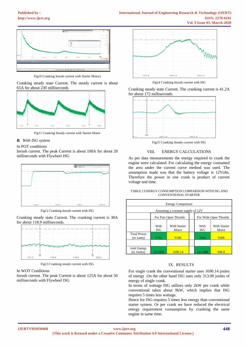
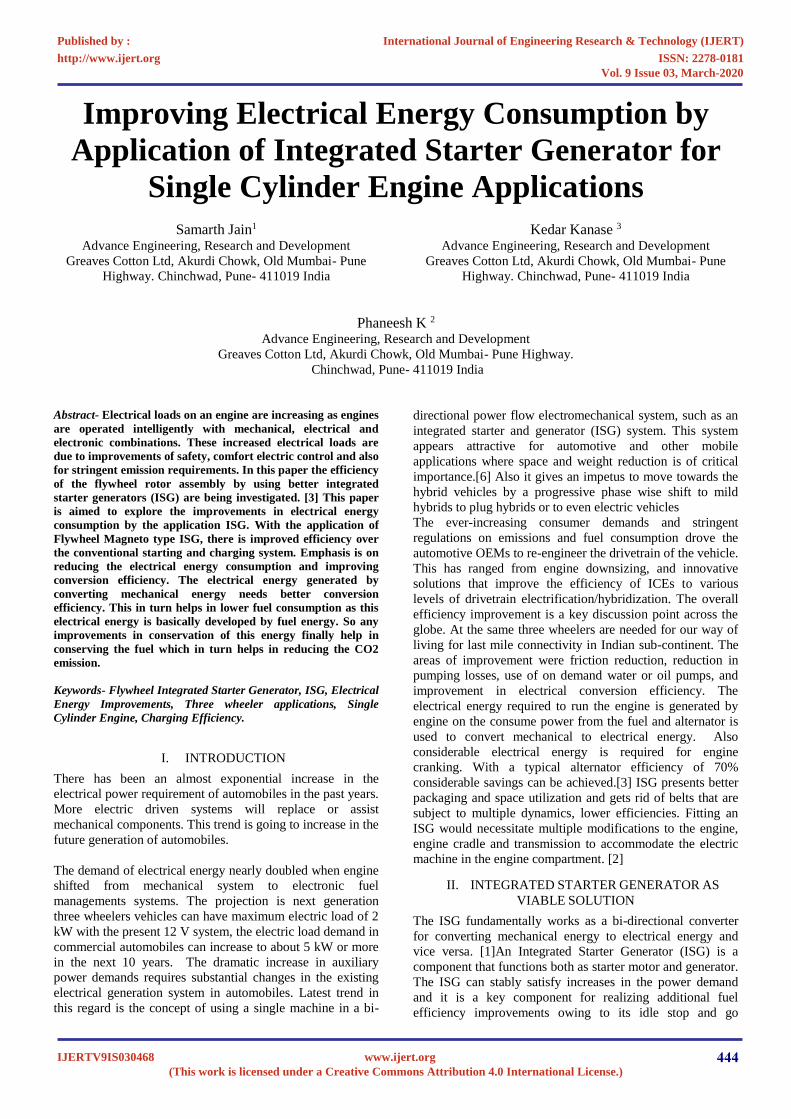
Fig10 Cranking Inrush current with Starter Motor)
Cranking steady state Current. The steady current is about
65A for about 230 milliseconds
Fig11 Cranking Steady current with Starter Motor
B. With ISG system
In POT conditions
Inrush current. The peak Current is about 108A for about 20
milliseconds with Flywheel ISG
Fig12 Cranking Inrush current with ISG
Cranking steady state Current. The cranking current is 38A
for about 118.9 milliseconds.
Fig13 Cranking steady current with ISG
In WOT Conditions
Inrush current. The peak Current is about 125A for about 50
milliseconds with Flywheel ISG
Fig14 Cranking Inrush current with ISG
Cranking steady state Current. The cranking current is 41.2A
for about 172 milliseconds.
Fig15 Cranking Steady current with ISG
VIII. ENERGY CALCULATIONS
As per data measurements the energy required to crank the
engine were calculated. For calculating the energy consumed
the area under the current curve method was used. The
assumption made was that the battery voltage is 12Volts.
Therefore the power in one crank is product of current
voltage and time.
TABLE 2 ENERGY CONSUMPTION COMPARISON WITH ISG AND
CONVENTIONAL STARTER
Energy Comparison
Assuming a constant supply of 12V
For Part Open Throttle For Wide Open Throttle
With
ISG
With Starter
Motor
With
ISG
With Starter
Motor
Total Power
(in watts) 1752 9186 2004 9288
total Energy (in Joules) 313.008 1690.14 161.688 946.8
IX. RESULTS
For single crank the conventional starter uses 1690.14 joules
of energy .On the other hand ISG uses only 313.08 joules of
energy of single crank.
In terms of wattage ISG utilizes only 2kW per crank while
conventional takes about 9kW, which implies that ISG
requires 5 times less wattage.
Hence for ISG requires 5 times less energy than conventional
starter system. Or per crank we have reduced the electrical
energy requirement consumption by cranking the same
engine in same time.
IJERTV9IS030468(This work is licensed under a Creative Commons Attribution 4.0 International License.)
www.ijert.org 448
International Journal of Engineering Research & Technology (IJERT)
ISSN: 2278-0181http://www.ijert.org
Published by :
Vol. 9 Issue 03, March-2020
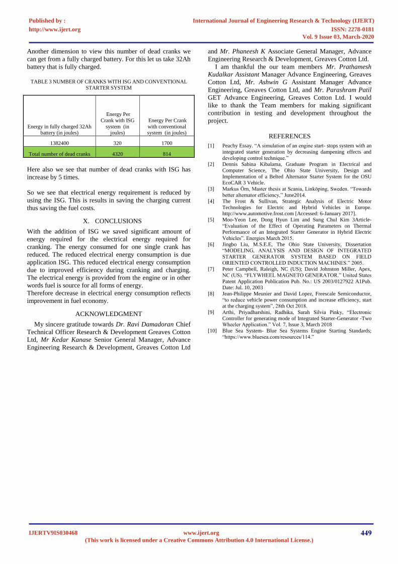
Another dimension to view this number of dead cranks we
can get from a fully charged battery. For this let us take 32Ah
battery that is fully charged.
TABLE 3 NUMBER OF CRANKS WITH ISG AND CONVENTIONAL
STARTER SYSTEM
Energy in fully charged 32Ah battery (in joules)
Energy Per
Crank with ISG
system (in joules)
Energy Per Crank
with conventional system (in joules)
1382400 320 1700
Total number of dead cranks 4320 814
Here also we see that number of dead cranks with ISG has
increase by 5 times.
So we see that electrical energy requirement is reduced by
using the ISG. This is results in saving the charging current
thus saving the fuel costs.
X. CONCLUSIONS
With the addition of ISG we saved significant amount of
energy required for the electrical energy required for
cranking. The energy consumed for one single crank has
reduced. The reduced electrical energy consumption is due
application ISG. This reduced electrical energy consumption
due to improved efficiency during cranking and charging.
The electrical energy is provided from the engine or in other
words fuel is source for all forms of energy.
Therefore decrease in electrical energy consumption reflects
improvement in fuel economy.
ACKNOWLEDGMENT
My sincere gratitude towards Dr. Ravi Damadoran Chief
Technical Officer Research & Development Greaves Cotton
Ltd, Mr Kedar Kanase Senior General Manager, Advance
Engineering Research & Development, Greaves Cotton Ltd
and Mr. Phaneesh K Associate General Manager, Advance
Engineering Research & Development, Greaves Cotton Ltd.
I am thankful the our team members Mr. Prathamesh
Kudalkar Assistant Manager Advance Engineering, Greaves
Cotton Ltd, Mr. Ashwin G Assistant Manager Advance
Engineering, Greaves Cotton Ltd, and Mr. Parashram Patil
GET Advance Engineering, Greaves Cotton Ltd. I would
like to thank the Team members for making significant
contribution in testing and development throughout the
project.
REFERENCES
[1] Peachy Essay. “A simulation of an engine start- stops system with an
integrated starter generation by decreasing dampening effects and
developing control technique.”[2] Dennis Sabina Kibalama, Graduate Program in Electrical and
Computer Science, The Ohio State University, Design and
Implementation of a Belted Alternator Starter System for the OSU EcoCAR 3 Vehicle.
[3] Markus Örn, Master thesis at Scania, Linköping, Sweden. “Towards
better alternator efficiency,” June2014. [4] The Frost & Sullivan, Strategic Analysis of Electric Motor
Technologies for Electric and Hybrid Vehicles in Europe.http://www.automotive.frost.com [Accessed: 6-January 2017].
[5] Moo-Yeon Lee, Dong Hyun Lim and Sung Chul Kim 3Article-
“Evaluation of the Effect of Operating Parameters on ThermalPerformance of an Integrated Starter Generator in Hybrid Electric
Vehicles”. Energies March 2015.
[6] Jingbo Liu, M.S.E.E, The Ohio State University, Dissertation“MODELING, ANALYSIS AND DESIGN OF INTEGRATED
STARTER GENERATOR SYSTEM BASED ON FIELD
ORIENTED CONTROLLED INDUCTION MACHINES.” 2005. [7] Peter Campbell, Raleigh, NC (US); David Johnston Miller, Apex,
NC (US). “FLYWHEEL MAGNETO GENERATOR.” United States
Patent Application Publication Pub. No.: US 2003/0127922 A1Pub. Date: Jul. 10, 2003
[8] Jean-Philippe Meunier and David Lopez, Freescale Semiconductor,
“to reduce vehicle power consumption and increase efficiency, start at the charging system”, 28th Oct 2018.
[9] Arthi, Priyadharshini, Radhika, Sarah Silvia Pinky, “Electronic
Controller for generating mode of Integrated Starter-Generator -TwoWheeler Application.” Vol. 7, Issue 3, March 2018
[10] Blue Sea System- Blue Sea Systems Engine Starting Standards;
“https://www.bluesea.com/resources/114.”
IJERTV9IS030468(This work is licensed under a Creative Commons Attribution 4.0 International License.)
www.ijert.org 449
International Journal of Engineering Research & Technology (IJERT)
ISSN: 2278-0181http://www.ijert.org
Published by :
Vol. 9 Issue 03, March-2020