Embed Size (px)
Citation preview

i
Improving Heat Rate on Combined Cycle
Power Plants
C-18--EDF
to:
Environmental Defense Fund 257 Park Avenue South
New York, NY 10010
October 3 2018
Andover Technology Partners
112 Tucker Farm Road, North Andover, MA 01845
phone: (978) 683-9599; e-mail: staudt@AndoverTechnology

Andover Technology Partners 112 Tucker Farm Road, North Andover, MA 01845

www.AndoverTechnology.com 1
Contents
Executive Summary ....................................................................................................................................... 3
I. Introduction to Natural Gas Combined Cycle Power Plants ................................................................. 5
1.1 Gas Turbine Brayton Cycle .................................................................................................................. 5
1.2 Steam Rankine Cycle Plant .................................................................................................................. 6
1.3 Changes in operation of and advancements in combined cycle gas turbine plants........................... 7
2. Methods to improve the heat rate of the gas turbine through add-on inlet cooling or intercooling .... 10
2.1 Compressor Inlet Cooling (Turbine Inlet Cooling) and Intercooling Methods .................................. 10
2.2 Potential for TIC penetration ............................................................................................................ 19
3. Methods to improve the heat rate of the gas turbine through improvements to turbine, compressor
and combustor parts, pressure drop reduction and maintenance ............................................................ 20
3.1 Methods for improving turbine, compressor and combustor .......................................................... 20
3.2 Pressure Drop Reduction .................................................................................................................. 24
3.3 Maintenance efforts ......................................................................................................................... 24
4. Methods to Improve the Heat Rate of the Steam Plant ..................................................................... 25
4.1 Turbine upgrade .......................................................................................................................... 25
4.2 Condenser upgrades and cleaning .................................................................................................... 26
4.3. Rebuilding boiler feed pumps .......................................................................................................... 26
4.4. Installation of variable speed drives for pumps and blowers .......................................................... 26
4.5. Minimizing Steam System Losses .................................................................................................... 27
4.6 Costs of upgrades ............................................................................................................................. 27
5.0 The opportunity for gas and steam turbine upgrades ......................................................................... 28

www.AndoverTechnology.com 2
Figures
Figure 1. Open Brayton Cycle ........................................................................................................................ 5
Figure 2. Simplified diagram of a combined cycle power plant .................................................................... 6
Figure 3. Simplified diagram of NGCC steam plant ....................................................................................... 7
Figure 4. Natural Gas Price History to the Electric Power Industry ............................................................. 8
Figure 5. Installation of Natural Gas Combined Cycle Power Plants ............................................................ 9
Figure 6. Operating heat rates of coal- and natural gas-fired electricity generation (Btu/kWh) ................ 9
Figure 7. Effect of compressor inlet temperature on Heat Rate, Output, Exhaust Flow, and Heat
Consumption (fuel input) on a simple cycle gas turbine power plant ........................................................ 10
Figure 8. GE Spray Intercooling (SPRINT) on a GE LM 6000 turbine .......................................................... 12
Figure 9. Wet Compression or Overspray Technology ............................................................................... 13
Figure 10. Effects of TIC Technology on Capacity Enhancement Potential ................................................ 15
Figure 11. Example of the Effects of TIC Technology on the Capital Cost of Capacity Enhancement ........ 16
Figure 12. Comparison of Heat Rate and CO2 Emissions from NGCC, Simple Cycle and Thermal plants at
95°F dry bulb and 78°F wet bulb ................................................................................................................. 17
Figure 13. Inlet cooling can reduce CO2 emissions of combined cycle plants by about 30% ..................... 18
Figure 14. Effect of air bleed on output and heat rate as a function of ambient temperature ................. 22
Figure 15. Upgrade opportunities for Steam Turbine ................................................................................ 25
Figure 16. Trends in United States NGCC capacity over 20 years old assuming no retirements .............. 29
www.AndoverTechnology.com 3
Executive Summary
This report reviews several technologies that offer the potential for improving heat rates of combined
cycle power plants. There are several technologies that offer substantial promise.
Turbine inlet cooling (TIC) and related technologies, such as wet compression, offer the potential to
improve output of the turbine generator and improve heat rate at elevated ambient temperatures.
These technologies have been installed at over 400 facilities worldwide, with about half in the United
States. While the benefits are greatest in warm climates, and this is where most facilities are located,
these have also been installed in more moderate climates, such as Nebraska, New York, Connecticut,
Pennsylvania, Massachusetts, New Jersey, Maine and Maryland. This is a technology that can be
deployed quickly and can have a low capital cost. Moreover, although it is estimated to already have a
significant market penetration, there is still a long way to go so that more improvements are possible. In
the range of 2% improvement in heat rate is possible for a natural gas combined cycle plant at full load
(including the increased output from TIC), depending upon ambient conditions. If dispatch
considerations are made, the overall effect on heat rate is higher because increased capacity from TIC is
achieved more efficiently than increased capacity from use of Heat Recovery Steam Generator duct
burners.
Upgrading of gas turbine components is another promising approach that is offered by the various
turbine manufacturers as well as aftermarket suppliers. Older turbines can benefit from replacement of
existing components with newer components with improved designs or materials that offer the
potential for heat rate improvements over the original equipment. These offer the potential for heat
rate improvements for NGCC plants on the order of 3% depending upon the circumstances.
There are also several approaches that can be used to improve the heat rate of the steam system.
Steam turbine upgrades or overhauls, condenser cleaning, and rebuilding of feed pumps are among the
means that may offer NGCC heat rate improvements on the order of 3% or more. Installation of variable
speed drives for pumps and fans can improve heat rate by reducing parasitic loads. In addition, there
are operating and maintenance practices that will minimize losses in the steam system.
The opportunity for upgrading gas turbine and steam turbine systems in the Natural Gas Combined
Cycle (NGCC) plant is growing. Within a few years well over half of the currently installed base of NGCC
plants will be in excess of 20 years old. This means that worn out or dated equipment can be replaced
with newer equipment with potentially improved technology. The total heat rate improvement possible
for any facility will vary depending upon its circumstances. Nevertheless, through gas turbine upgrades,
steam plant upgrades and TIC about 6% or greater heat rate improvement may be possible. Because
each of these heat rate improvement methods also comes with the benefit of increased output, the cost
may be compared against the cost of new capacity. The cost of this increased output is typically well
below that of new capacity.

www.AndoverTechnology.com 4
Table 1 shows approximate values for heat rate improvement, capacity increase and estimated capital
cost (2017 dollars) for some of the methods discussed in this report. Capital cost was estimated by
taking some of the reported costs in this report, normalizing to total NGCC plant output rather than
increase in output or steam plant output, and adjusting to 2017 dollars using the Chemical Engineering
Plant Cost Index. It is important to keep in mind that for any given project the heat rate improvement
(HRI), the capacity increase and the capital cost may vary significantly from these values depending upon
the actual temperature, humidity or the particular design of the NGCC plant.
Table 1. Approximate heat rate improvement, capacity increase and capital cost (2017$) relative to NGCC plant heat rate, capacity and total NGCC plant output
Technology Approx. NGCC HRI % Capacity Increase %
Capital Cost $/kW
Inlet fogging 2.0% 6% $0.93
Wetted Media 2.0% 6% $0.90
Wet Compression 1.3% 11% $10
Inlet Chiller 2.0% 11% $19
Gas Turbine Upgrade 3.0% 13% $172
Steam Turbine Upgrade 3.2% 3% $130

www.AndoverTechnology.com 5
I. Introduction to Natural Gas Combined Cycle Power Plants A NGCC power plant is distinguished as being comprised of two power cycles: a gas turbine Brayton
cycle; and a steam Rankine cycle.
1.1 Gas Turbine Brayton Cycle Gas turbines are considered Open Brayton Cycles, as depicted in Figure 1, and operate by:
first compressing air to a high pressure,
then adding fuel and combusting the high pressure fuel and air mixture in a combustor or
combustion chamber, and
then producing power by expanding the hot, high pressure gases in a turbine that produces
power,
the power from the turbine drives the compressor and the remainder is available to power a
generator.
In fact, the power consumed by the compressor is on the order of two thirds of the output of the
turbine. Therefore, techniques that reduce the power consumed by the compressor can have a large
impact on efficiency.
Figure 1. Open Brayton Cycle1
In a Simple Cycle configuration, the Open Brayton Cycle would be stand alone and the exhaust gases
from the turbine would be released to the atmosphere. However, these gases have substantial energy
value since they have temperatures on the order of 900°F. To utilize the energy that is available in the
turbine exhaust gas, the hot gases pass through a Heat Recovery Steam Generator (HRSG) and heat
water into steam to drive a steam turbine, as shown in Figure 2. In fact, in most cases additional fuel is
added to the exhaust gases from the turbine because there is substantial excess oxygen available in the
turbine exhaust to react with fuel. The fuel is combusted in order to increase the exhaust gas
1 Massachusetts Institute of Technology,
http://web.mit.edu/16.unified/www/SPRING/propulsion/notes/node27.html
www.AndoverTechnology.com 6
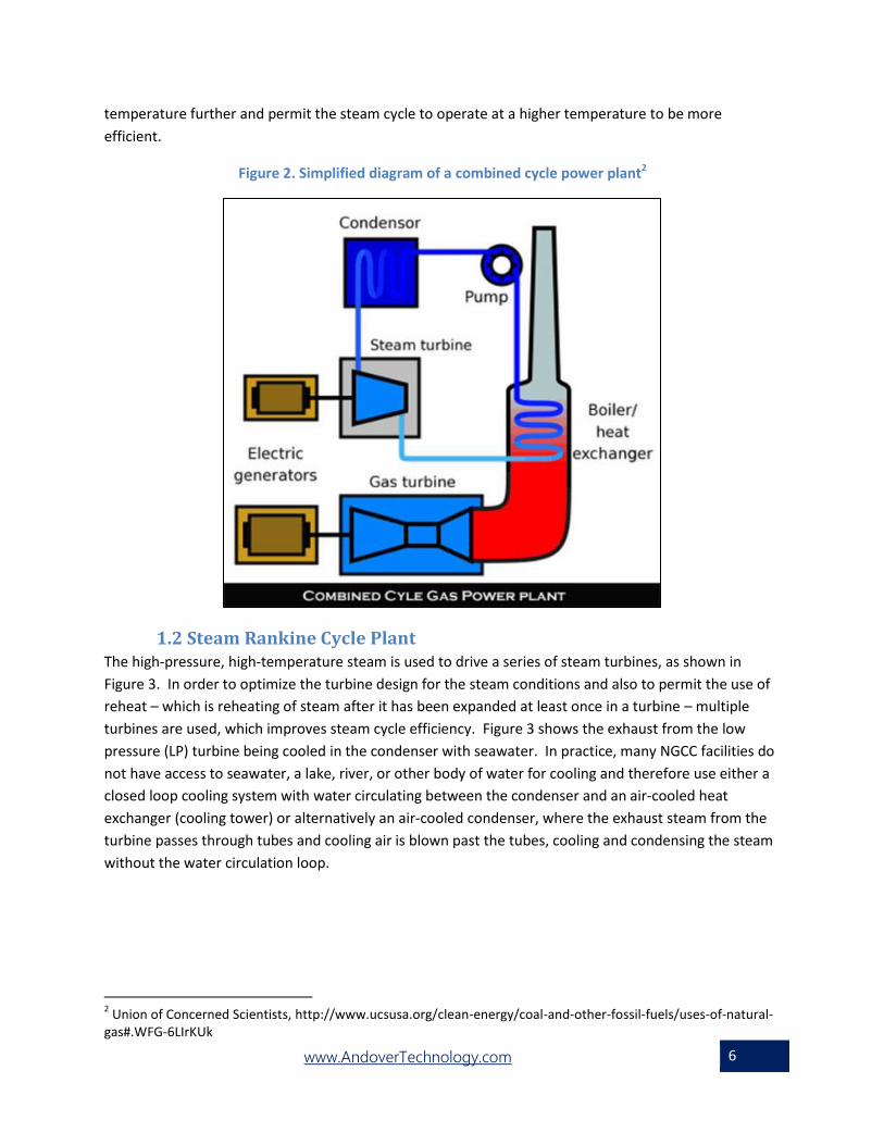
temperature further and permit the steam cycle to operate at a higher temperature to be more
efficient.
Figure 2. Simplified diagram of a combined cycle power plant2
1.2 Steam Rankine Cycle Plant The high-pressure, high-temperature steam is used to drive a series of steam turbines, as shown in
Figure 3. In order to optimize the turbine design for the steam conditions and also to permit the use of
reheat – which is reheating of steam after it has been expanded at least once in a turbine – multiple
turbines are used, which improves steam cycle efficiency. Figure 3 shows the exhaust from the low
pressure (LP) turbine being cooled in the condenser with seawater. In practice, many NGCC facilities do
not have access to seawater, a lake, river, or other body of water for cooling and therefore use either a
closed loop cooling system with water circulating between the condenser and an air-cooled heat
exchanger (cooling tower) or alternatively an air-cooled condenser, where the exhaust steam from the
turbine passes through tubes and cooling air is blown past the tubes, cooling and condensing the steam
without the water circulation loop.
2 Union of Concerned Scientists, http://www.ucsusa.org/clean-energy/coal-and-other-fossil-fuels/uses-of-natural-
gas#.WFG-6LIrKUk

www.AndoverTechnology.com 7
Figure 3. Simplified diagram of NGCC steam plant3
For NGCC plants, the total MW capacity of the plant is equal to the sum of the output of the steam
turbine generator and the output of the gas turbine generator. The output of the gas turbine generator
portion of the plant is typically in the range of about 60% to 67% of the total output of both generators.
In some cases there may be more than one gas turbine exhausting into a single HRSG.
1.3 Changes in operation of and advancements in combined cycle gas turbine
plants For many years NGCC power plants were dispatched after coal plants due to the higher cost of natural
gas fuel; however, the shale revolution and increased availability and low cost of natural gas in recent
years have caused NGCC plants to dispatch ahead of many coal plants. Figure 4 shows the historical
price of natural gas supplied to the electric generating industry. As shown, natural gas prices are near
historical lows and prices for the utility sector are forecasted to grow at only a 1.4% annual rate through
2050.4 This has resulted in changes in operations for NGCC plants, resulting in higher capacity factors.
In fact, since 2015 the average capacity factor of NGCC power plants in the US has exceeded that of coal
fired power plants (54.8%-55.9% for NGCC versus 53.3%-54.7% for coal).5 Due to the higher capacity
factors versus historical levels, NGCC plants will experience more frequent maintenance intervals and
may find investment in improvements more economically attractive than in the past when capacity
factors were lower.
3 Department of Energy, https://www.netl.doe.gov/research/coal/energy-systems/gasification/gasifipedia/igcc-
process 4 Energy Information Administration, Annual Energy Outlook, 2018
5 Energy Information Administration,
https://www.eia.gov/electricity/monthly/epm_table_grapher.cfm?t=epmt_6_07_a

www.AndoverTechnology.com 8
NGCC plants have also been impacted by the increasing penetration of variable renewable energy. A
priority for NGCC plants is the ability to quickly increase or decrease power output in response to
variable renewable energy, which can adversely impact heat rate. Because they have lower heat rates
and are less polluting per MWh of electricity produced than combustion turbines or coal plants, NGCC
plants are preferable for supplying power than these other fossil fuel sources. On the other hand,
combustion turbines are better suited for rapid starts and load changes than NGCC plants.
Figure 4. Natural Gas Price History to the Electric Power Industry6
Moreover, technology has improved. As demonstrated in Figure 5, the peak in installation of natural gas
combined cycle power plants occurred in the 2002-2003 time period, roughly fifteen years ago. Newer
NGCC plants utilize advanced materials that permit operation at higher temperatures and higher
efficiencies. New designs for seals and other components reduce losses. For existing NGCC plants
replacement parts of superior design and materials than the original create opportunities for improved
performance and reliability. In addition to advanced materials, other methods for improving the
performance of NGCC plants have been developed over time that can be deployed.
Figure 6 shows trends in fleet-wide heat rates for operating coal and gas fired generation. While coal
fired generation heat rates have increased, gas fired generation heat rates have decreased largely due
to retirement of older, less efficient generation (including natural gas steam plants) and deployment of
newer, more efficient gas-fired generation. State-of-the-art NGCC plants now offer thermal efficiencies
in excess of 60%.
For existing generation, however, there are options for improving the efficiency of NGCC plants. The
methods for improvement can be broken down into:
Methods to improve the efficiency of the gas turbine, or
Methods to improve the efficiency of the steam plant.
6 US Energy Information Administration, https://www.eia.gov/dnav/ng/hist/n3045us3m.htm

www.AndoverTechnology.com 9
Figure 5. Installation of Natural Gas Combined Cycle Power Plants7
Figure 6. Operating heat rates of coal- and natural gas-fired electricity generation (Btu/kWh)8
7 Developed from US EPA data
8 https://www.eia.gov/todayinenergy/detail.php?id=32572
www.AndoverTechnology.com 10
2. Methods to improve the heat rate of the gas turbine through add-on
inlet cooling or intercooling This section will address add-on methods that improve gas turbine output and heat rate through inlet
and compressor intercooling methods.
2.1 Compressor Inlet Cooling (Turbine Inlet Cooling) and Intercooling
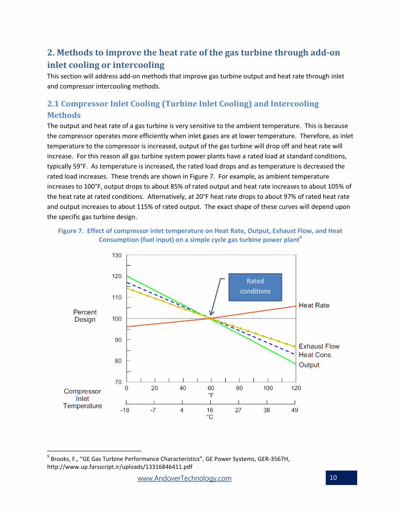
Methods The output and heat rate of a gas turbine is very sensitive to the ambient temperature. This is because
the compressor operates more efficiently when inlet gases are at lower temperature. Therefore, as inlet
temperature to the compressor is increased, output of the gas turbine will drop off and heat rate will
increase. For this reason all gas turbine system power plants have a rated load at standard conditions,
typically 59°F. As temperature is increased, the rated load drops and as temperature is decreased the
rated load increases. These trends are shown in Figure 7. For example, as ambient temperature
increases to 100°F, output drops to about 85% of rated output and heat rate increases to about 105% of
the heat rate at rated conditions. Alternatively, at 20°F heat rate drops to about 97% of rated heat rate
and output increases to about 115% of rated output. The exact shape of these curves will depend upon
the specific gas turbine design.
Figure 7. Effect of compressor inlet temperature on Heat Rate, Output, Exhaust Flow, and Heat Consumption (fuel input) on a simple cycle gas turbine power plant9
9 Brooks, F., “GE Gas Turbine Performance Characteristics”, GE Power Systems, GER-3567H,
http://www.up.farsscript.ir/uploads/13316846411.pdf
Rated
conditions

www.AndoverTechnology.com 11
Lower compressor inlet temperature can be achieved in a number of ways:
Inlet cooling – This is cooling the inlet air prior to admission to the compressor
Intercooling – This is cooling that occurs between compressor stages.
The Turbine Inlet Cooling Association’s database10 shows over 400 installations of different forms of
inlet cooling or intercooling with 221 in the United States. These are mostly installed in warm climates
(California, Texas, Florida, Georgia), but also in very moderate climates (Illinois, Colorado, Connecticut,
Maryland, Massachusetts, Maine, Michigan). While the benefits are greatest in warm climates, and this
is where most TIC-equipped facilities are located, there are significant benefits in moderate and cooler
climates as well.
Inlet cooling can be performed in a number of ways. One method may be use of refrigeration chillers
powered by electricity or absorption chillers using waste heat. Mechanical refrigeration systems
consume power; but, the increased power produced by the turbine is about 3 to 4 times the power
demand of the refrigeration system used to cool the inlet air. Absorption chilling systems use low
pressure steam and very low amounts of electrical power and may be preferred where steam is
available. Chilling systems do not require the consumption of demineralized water, can be net
producers of water depending upon the humidity of the gas, and can achieve lower inlet temperatures
than methods that rely upon humidification.
Other means of inlet cooling rely upon humidification. One method is pulling the inlet gas through a
wetted media where moisture is evaporated. This is called evaporative cooling. The other
humidification method is inlet fogging, where moisture is sprayed into the inlet gases as a fine mist.
Demineralized water is not required, but it does reduce the potential for deposit build up on and
corrosion of compressor components. Evaporative cooling is less likely to need demineralized water
since the deposits will build up on the cooling media that is periodically changed or cleaned. The
amount of temperature reduction by evaporative cooling or fogging is limited by the increased moisture
level in the gas that raises the dew point temperature, however evaporative cooling and fogging have
two advantages over chilling: 1) they are very simple to deploy, involving simple equipment that can be
installed in days, and; 2) the increased mass flow from the moisture will increase turbine output
somewhat.
Inlet cooling by any of the methods increases gas turbine output by reducing the compressor load. It
also increases efficiency, reducing heat rate.
The additional capacity available from any of the inlet cooling methods is at a capital cost that is well
below the cost of a new combustion turbine.11 This additional capacity is also available when it is most
needed – on hot days when power demand is greatest. Inlet cooling methods – especially those that
rely on humidification - are limited by the dew point temperature. But, that can be addressed through
intercooling or overspray.
10
http://www.turbineinletcooling.org/data/ticadatap.pdf 11
Turbine Inlet Cooling Association, “Turbine Inlet Cooling – A valuable tool to increase electric energy production”, March 2012, costs in one case study range from $15/kW for fogging or wet media to $183/kW for chillers, while new capacity is in the range of $830/kW
www.AndoverTechnology.com 12
Intercooling can be performed with heat exchangers installed between compressor stages; however,
this is normally impractical for an existing turbine. There are other wet approaches available for
intercooling. These can be very effective because as the gas is compressed, the difference between the
dry and wet bulb temperatures increase.
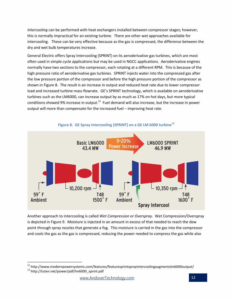
General Electric offers Spray Intercooling (SPRINT) on its aeroderivative gas turbines, which are most
often used in simple cycle applications but may be used in NGCC applications. Aeroderivative engines
normally have two sections to the compressor, each rotating at a different RPM. This is because of the
high pressure ratio of aeroderivative gas turbines. SPRINT injects water into the compressed gas after
the low pressure portion of the compressor and before the high pressure portion of the compressor as
shown in Figure 8. The result is an increase in output and reduced heat rate due to lower compressor
load and increased turbine mass flowrate. GE’s SPRINT technology, which is available on aeroderivative
turbines such as the LM6000, can increase output by as much as 17% on hot days, but more typical
conditions showed 9% increase in output.12 Fuel demand will also increase, but the increase in power
output will more than compensate for the increased fuel – improving heat rate.
Figure 8. GE Spray Intercooling (SPRINT) on a GE LM 6000 turbine13
Another approach to intercooling is called Wet Compression or Overspray. Wet Compression/Overspray
is depicted in Figure 9. Moisture is injected in an amount in excess of that needed to reach the dew
point through spray nozzles that generate a fog. This moisture is carried in the gas into the compressor
and cools the gas as the gas is compressed, reducing the power needed to compress the gas while also
12
http://www.modernpowersystems.com/features/featuresprintsprayintercoolingaugmentslm6000output/ 13
http://tuten.net/power/pdf/lm6000_sprint.pdf
www.AndoverTechnology.com 13
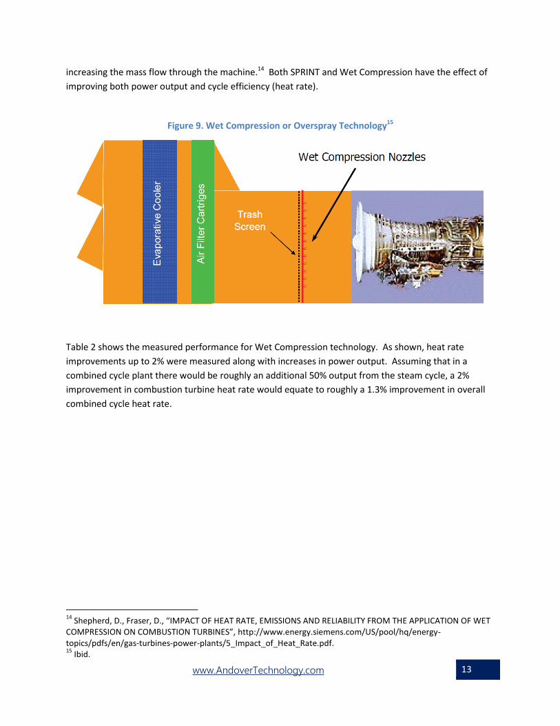
increasing the mass flow through the machine.14 Both SPRINT and Wet Compression have the effect of
improving both power output and cycle efficiency (heat rate).
Figure 9. Wet Compression or Overspray Technology15
Table 2 shows the measured performance for Wet Compression technology. As shown, heat rate
improvements up to 2% were measured along with increases in power output. Assuming that in a
combined cycle plant there would be roughly an additional 50% output from the steam cycle, a 2%
improvement in combustion turbine heat rate would equate to roughly a 1.3% improvement in overall
combined cycle heat rate.
14
Shepherd, D., Fraser, D., “IMPACT OF HEAT RATE, EMISSIONS AND RELIABILITY FROM THE APPLICATION OF WET COMPRESSION ON COMBUSTION TURBINES”, http://www.energy.siemens.com/US/pool/hq/energy-topics/pdfs/en/gas-turbines-power-plants/5_Impact_of_Heat_Rate.pdf. 15
Ibid.

www.AndoverTechnology.com 14
Table 2. Effects of Wet Compression on power output and heat rate16
N.D.: Not Determined DLN: Dry Low NOx
Comparison of power enhancement for various technologies on a 500 MW NGCC plant are shown in
16
Shepherd, D., Fraser, D., “IMPACT OF HEAT RATE, EMISSIONS AND RELIABILITY FROM THE APPLICATION OF WET COMPRESSION ON COMBUSTION TURBINES”, http://www.energy.siemens.com/US/pool/hq/energy-topics/pdfs/en/gas-turbines-power-plants/5_Impact_of_Heat_Rate.pdf

www.AndoverTechnology.com 15
Figure 10. As shown, electric chiller and wet compression have the highest potential for power
enhancement because they are not limted by the dew point temperature. Hence, electric chiller and
wet compression are less sensitive to the wet bulb temperature than the wet inlet cooling methods.

www.AndoverTechnology.com 16
Figure 11 compares the economics of capacity improvement (initial capital cost in $/MW) between new
generation (no cooling) for F-class NGCC plant and implementation of cooling on existing generation. As
shown, new capacity is much more expensive than any of the TIC options. Chillers are the most
expensive TIC option, but they do have advantages to the other approaches such as no need for water
and no wet bulb temperature limitation. Note that these costs are the costs per unit of additional
power output associated with TIC, not total NGCC plant output. To estimate cost per unit of total plant
output these values would be multiplied by the percent increase in NGCC plant output so that if the
NGCC plant output increased by 6% as a result of inlet fogging, then the cost would equal 0.06*$15/kW,
or $900/MW.

www.AndoverTechnology.com 17
Figure 10. Effects of TIC Technology on Capacity Enhancement Potential for
500MW NGCC plant 17
17
Turbine Inlet Cooling Association, “Turbine Inlet Cooling – A valuable tool to increase electric energy production”, March 2012

www.AndoverTechnology.com 18
Figure 11. Example of the Effects of TIC Technology on the Capital Cost of Capacity Enhancement18
Table 3 shows the economics as well as the performance impact of inlet fogging, evaporative cooling,
and wet compression on a Pratt & Whitney FT-4C Twin Pac operating at 90°F ambient temperatures.19
Chilling is not shown, but could potentially provide higher improvements in efficiency. As shown, there
is roughly a 0.9% improvement in efficiency (equivalent to 2.9% improvement in heat rate) for the inlet
cooling cases, which would equate to roughly 0.6% efficiency improvement (2% improvement in heat
rate20) if these turbines were used in a combined cycle mode. Wet compression also improves
efficiency, but to a lesser extent. However, wet compression will provide a larger boost to power than
either evaporative cooling or inlet fogging because it effectively provides the benefit of inlet fogging
with the additional benefit of wet intercooling. The efficiency and heat rate improvements for wet
intercooling are not as great as for inlet fogging or wet media cooling methods (0.5% efficiency gain and
1.6% reduction in heat rate in simple cycle case that would equate to roughly 1% heat rate reduction in
combined cycle configuration). In each case fuel use increases over the base case; however, power
output increases by a greater percentage. In each case capital cost is modest, in the range of $50/kW
(2004 dollars).
18
Ibid 19
This is two FT-4C simple-cycle turbines driving a single generator for a combined output of about 58 MWe 20
Heat rate improvements are calculated from heat input and power output data

www.AndoverTechnology.com 19
Table 3. Economic and performance Impact of Evaporative Cooling with Wet Media, Inlet Fogging and Wet Compression on a Pratt & Whitney FT-4C Twin Pac (2004 dollars)21
Figure 12 is a comparison of heat rate and CO2 emission rate for an F class NGCC, an F class NGCC with
inlet chilling, a simple cycle aeroderivative combustion turbine and a steam thermal plant. This does not
factor in the benefit possible from dispatch impacts by increasing plant output through TIC rather than
duct firing (or increases in steam plant output), which will improve heat rate from conventional NGCC
further.
Figure 12. Comparison of Heat Rate and CO2 Emissions from NGCC, Simple Cycle and Thermal plants at 95°F dry bulb and 78°F wet bulb22
So far, the heat rate improvements from TIC have been considered from the perspective of a plant at full
load. However, by increasing the capacity of combined cycle plants through TIC, there are other
benefits besides the aforementioned heat rate improvement to the combined cycle plant. TIC increases
21
Phillips, J, and Levine, P., “Boosting Gas Turbine Power”, Turbomachinery International, July/August 2004 22
Turbine Inlet Cooling Association, “Turbine Inlet Cooling – A valuable tool to increase electric energy production”, March 2012
www.AndoverTechnology.com 20
NGCC plant output and can be used prior to less fuel efficient methods of increasing generating output,
including:
Dispatch prior to use of NGCC duct burners to increase steam plant output
Dispatch prior to other plants using less efficient simple-cycle peaking capacity
Dispatch prior to other, less-efficient steam power plants
During high load periods it is possible to increase NGCC output using TIC. This is ideal because the
benefits of TIC are timed when demand is highest (high temperature periods) while also reducing the
overall heat rate of generation. The degree of improvement in heat rate will be determined by the
temperature, plant configuration, dispatch and the TIC technology choice. When dispatch is factored in,
the benefit of TIC in improving heat rate is potentially greater for NGCC plants than for simple cycle
plants because the increase in output from TIC is preferable to duct firing and will take priority over use
of duct burners for increased steam plant output. Power output of a 2x1 207FA combined cycle can be
raised to almost 580 MW from 452 MW on a 95F DB and 78F WB day by fogging to dew point for a 36.9
MW gain, chilling to 50F for another 16.9 MW, and supplementary duct firing for a 73.4 MW boost in
steam turbine output. 23 Fogging and chilling provide added output with a much lower impact on fuel
demand than duct firing.
As another example, a 1x1 F-Class combined cycle plant is considered in
Figure 13. This plant is rated at 260MW and 57% to 58% efficiency. Under 95F dry bulb and 78F wet
bulb temperature conditions, with inlet air cooling, the combined cycle plant will generate about 700 lb
of CO2 per MWh of generation (without duct burners) compared to 980 lb for the same plant without
cooling (with duct burners). Since CO2 emissions are directly related to fuel consumption, this equates
to a nearly 30% improvement in heat rate. Hence, by dispatching TIC to meet load prior to using duct
burners, overall operating heat rate is lower over the full dispatch range.
Figure 13. Inlet cooling can reduce CO2 emissions of combined cycle plants by about 30%24
23
“Gas Turbine Inlet Cooling – Scope, cost and performance for new and retrofit power plant projects”, Gas Turbine World, 2010 Handbook 24
“Gas Turbine Inlet Cooling – Scope, cost and performance for new and retrofit power plant projects”, Gas Turbine World, 2010 Handbook

www.AndoverTechnology.com 21
2.2 Potential for TIC penetration The Turbine Inlet Cooling Association identified the 20 states where TIC could be most beneficial.25 This
factored in the capacity installed, ambient temperatures, and other factors. It is possible to estimate the
amount of natural gas generation that could be impacted by TIC in these 20 states. This could be done
by comparing the total installations of NGCC plants with the number of TIC installations.
Just looking at the top 20 states, there are 233 GW of combined cycle capacity among 1549 combined
cycle systems.26 This accounts for about 83 % of the entire US combined cycle capacity (233 GW divided
by 282 GW for the entire United States). The portion of the combined cycle capacity that is from the gas
turbine as opposed to the steam turbine is generally on the order of 60%-65%. Therefore, roughly 146
GW of capacity could utilize TIC in these 20 states (146 GW is the gas turbine portion of the 233 GW of
combined cycle capacity in the 20 top states).
To determine the amount of capacity that is already equipped with TIC the TIC Association database was
examined. The database does not distinguish between combined cycle and simple cycle installations;
however, it does indicate the type of gas turbine and the MW capacity. From this it is possible to
estimate the capacity that is combined cycle. It is assumed that all aeroderivative gas turbines are
installed in a simple-cycle arrangement. This is a reasonable, but conservative, assumption because
some aeroderivative turbines are installed in combined cycle arrangements although they are most
frequently installed in simple cycle arrangements. Also, it is assumed that all large, frame type gas
turbines are installed in combined cycle arrangements. It is unusual for such turbines to be installed in
simple cycle arrangements. Using this methodology, TIC is installed on roughly 48.5 GW of capacity as
part of NGCC systems. These are installed in the 20 states that were determined to be most attractive
for TIC. Therefore, there is just under 100 GW (146 GW minus 48.5 GW) of gas turbine capacity installed
in combined cycle arrangements that could be retrofit with TIC in the 20 states that could most benefit
from TIC.
25
Punwani, D., “Turbine Inlet Cooling – Increasing Summer Peak Capacity & Reducing Overall Emissions”, TICA Presentation to the U.S. EPA in February 2014, August 24, 2016 26
This was determined from analysis of 2017 EIA Form 860 generator data and includes both gas turbine and steam turbine output.

www.AndoverTechnology.com 22
This does not include the remaining roughly 50 GW (282 GW minus 233 GW) of combined cycle that are
in the remaining 30 states. This equates to roughly 31 GW of gas turbine output. So, in total, close to
130 GW of gas turbine capacity in NGCC arrangements could potentially be retrofit with TIC in the entire
United States, although about 100 GW of that is in the 20 states that were determined to be most
attractive candidates for TIC.
The degree of heat rate improvement will vary by application. Location (dry and wet bulb
temperatures), choice of TIC technology, dispatch and other factors will play a role. However, heat rate
improvements on the order of 1%-2% in combined cycle mode are possible during periods of high
ambient temperature. This does not factor in the dispatch effects of dispatching the increased capacity
from TIC prior to less efficient generating methods, which reduces the effective heat rate further.
Retrofit costs will also vary by application. In situations where there are limitations on water use,
chillers (which have a higher capital cost) will offer an advantage over wet methods. Where water
availability is high, any of the wet methods, which have a lower capital cost than chilling, may be
preferred. In any case, the capital cost of any of these methods on a $/kW of increased capacity is well
below that of new simple-cycle capacity.
3. Methods to improve the heat rate of the gas turbine through
improvements to turbine, compressor and combustor parts, pressure
drop reduction and maintenance Existing gas turbines can be upgraded, resulting in improved performance and reliability. This is not only
due to degradation of components from wear and tear. It is also due to improved materials, designs and
methods for manufacture. Maintenance efforts also help to minimize degradation of performance.
3.1 Methods for improving turbine, compressor and combustor All of the major manufacturers and some aftermarket companies offer uprate packages that improve
performance and/or reliability. For example, GE offers at least 400 firing temperature uprates for their
heavy duty gas turbine field units.27 These improvements include new seal designs that reduce leakage,
improved inlet guide vanes to the compressor, improved turbine vanes and blades, and advanced
technology updates that include parts made of new materials or new designs. One example of this is
that GE has developed improved wire brush seals for the compressor shaft that work better than
labyrinth seals originally supplied on some existing units. The wire brush seals will provide tighter
clearances and less leakage; this individual improvement can increase output by about 1% and heat rate
by about 0.5%. High pressure packing seals on the turbine can also be replaced with brush seals,
particularly on GE’s frame 5, 7 and 9 units. Performance improvement is typically 0.3% in output and
0.2% heat rate.
Significant increases in output and heat rate are possible, as demonstrated in Tables 4 & 5, which
summarize uprate options for the GE MS6001B and MS7001B. GE also offers uprate packages for its
27
Johnston, J., “Performance and Reliability Improvements for Heavy-Duty Gas Turbines”, GER-3571H (summarizing uprate options for the GE MS6001B).

www.AndoverTechnology.com 23
other large gas turbines. Similar uprate options are available for a wide range of turbines from the
various manufacturers.
Table 4. Uprate summary for GE MS6001B28
Table 5. Uprate summary for GE MS7001B29
28
Ibid 29
Ginter, T. Bouvay, T., “Uprate Options for the MS7001 Heavy Duty Gas Turbine”

www.AndoverTechnology.com 24
An example of how new technology will improve output and heat rate is new turbine blade materials
and designs that reduce the need for bleed air to cool the turbine blades. Figure 14 shows the impact of
bleed air (air that is taken from the compressor discharge to cool turbine blades) on output and heat
rate. As shown, at an ambient temperature of 60F, a 10% bleed rate will increase heat rate by about
20% and decrease power output by over 20%.
Figure 14. Effect of air bleed on output and heat rate as a function of ambient temperature30
Use of advanced materials and manufacturing techniques will reduce the need for bleed air to cool
turbine blades and combustor parts. An alternative for NGCC plants is steam cooling for the turbine
blades, which offers the advantage of recovering the steam in a closed loop. This is available on GE’s H
class turbines and it allows for significantly higher turbine inlet temperature.31
Coatings –
Coatings can provide advantages in terms of heat resistance (for turbine blades and combustor
components), resistance to fouling (especially compressor blades), reduced surface friction, and
resistance to corrosion (especially if the turbine is located near saltwater).
The Combustion Turbine Combined Cycle Users Organization performed an analysis that showed that
adding a 10 mil coating to the 1st stage blades and vanes of a GE Frame 7EA would allow an increase in
30
Brooks, F., “GE Gas Turbine Performance Characteristics”, GER-3567H 31
Ibid

www.AndoverTechnology.com 25
firing temperature from 2020 °F to 2035 °F. The report calculated that this small increase could provide
$4 million of net revenue over the life of the coating.32
Another study by Fern Engineering, Inc. for the Electric Power Research Institute, Palo Alto, Calif.,
concluded that the addition of thermal barrier coatings to a GE Frame 7B would provide an increase of
5.5 MW in power (from 91 MW base power), at an incremental cost of $140/kW, a fraction of what new
capacity costs while also improving heat rate.33, 34
One utility had the coatings applied to the axial compressor of a W501F installed in combined cycle
service and compared performance against a sister unit. The results of testing showed that the unit with
the coated compressor had:
• Higher compressor efficiency of 0.64%
• Better heat rate, 0.58%
• Higher power output, 1.26%
The incremental capital cost of the capacity boost was approximately $60/kW.35
Other options to increase the mass flow through the compressor and often reduce losses include
installing higher flowrate inlet guide vanes (IGV) that are aerodynamically thinner and allow greater flow
into the compressor. On a Frame 7B, you can expect a 4.5% boost in power and a slight improvement in
heat rate − approximately 1%. The cost of new IGVs typically is less than $100/kW.36
Another approach to increase mass flowrate, output and improve heat rate is supercharging, which
amounts to adding a blower to the inlet of the compressor. This approach when used in combination
with inlet fogging increases power much more than the amount consumed by the blower.37
Comprehensive upgrades might include replacement of combustion liners, transition pieces, 1st stage
turbine vanes, and 2nd stage vanes and blades with Frame 7EA parts. For eight GE Frame 7B turbines
owned by Reliant Energy in Houston, this allowed operators to increase the firing temperature of the
machines by 170 deg F. After the upgrades, the eight machines yielded power increases of 16 to 26%,
while the heat rate decreased by 4.5 to 11% − improvements that are approximately three times greater
than what could have been expected from a normal overhaul using new Frame 7B parts. The cost for the
upgrades divided by the increase in power output was approximately $250/kW.38
Table 6 shows power, heat rate and capital cost impact of different turbine upgrade options – ranging
from the comprehensive upgrades that may be available from the manufacturer to less comprehensive
upgrades.
32 Phillips, J., Levine, P., “GAS TURBINE PERFORMANCE UPGRADE OPTIONS”,
http://www.fernengineering.com/pdf/gt_upgrade_options.pdf 33
Ibid 34
EIA’s 2018 Annual Energy Outlook Table 2 indicates new combustion turbine capacity at $680/kW to $1107/kW and combined cycle at $982/kW to $1108/kW. http://www.eia.gov/outlooks/aeo/assumptions/pdf/electricity.pdf 35
Phillips, J., Levine, P., “GAS TURBINE PERFORMANCE UPGRADE OPTIONS”, http://www.fernengineering.com/pdf/gt_upgrade_options.pdf 36
Ibid 37
Ibid 38
ibid

www.AndoverTechnology.com 26
Table 6. MW impact, Heat Rate benefit impact, and capital cost of different turbine upgrade options (2002 dollars)39
3.2 Pressure Drop Reduction A reduction in pressure drop in the HRSG gas pathway will improve turbine output and heat rate. This
can be achieved with newly available Selective Catalytic Reduction (SCR) and carbon monoxide (CO)
catalysts that have lower volumes and therefore lower pressure losses than before. In this case at least
20% reduction in total catalyst pressure drop can be achieved with newer combination catalysts.40 This
will result in a heat rate improvement, the magnitude of which will depend upon the pressure ratio of
the turbine.
3.3 Maintenance efforts Regular HRSG cleaning is beneficial to maintaining low pressure drop across the HRSG. Although natural
gas has very low sulfur levels, some ammonium bisulfate can accumulate in the HRSG, leading to
pressure losses. Other contaminants can build up on the HRSG over time. With increased operation of
combined cycle plants regular HRSG cleaning will become more important. The extent of the
improvement in output will depend upon the degree of the deposit and the turbine pressure ratio. One
example is described in a Case Study on GE’s Pressurewave HRSG cleaning technology. After one
cleaning effort removed three tons of debris from the HRSG of a NGCC facility, GE removed an
additional 14 tons of debris, and reduced turbine back pressure by 8 inches water column, with net
annual fuel savings or increased power output estimated at $500,000/year.41
39
Ibid 40
Niklas Jakobsson & Hans Jensen-Holm, “Catalytic multi-pollutant abatement of gas turbine exhaust”, Haldor Topsoe, http://www.topsoe.com/sites/default/files/catalytic_multi_pollutant_abatement_of_gas_turbine_exhaust.ashx__2.pdf 41
GE Power, “When is a 28,000 lb rust pile a good thing?”, GEA32737 (08/2016), https://powergen.gepower.com/content/dam/gepower-pgdp/global/en_US/documents/service/hrsg%20services/pressurewave-case-study.pdf

www.AndoverTechnology.com 27
Gas turbine flow path components also suffer degradation and build up. Regular cleaning of or
replacement of components is therefore an important part of maintenance. With increased operation,
increased maintenance will be necessary.
4. Methods to Improve the Heat Rate of the Steam Plant Many of the improvements to the steam plant available to NGCC operators are similar to what is
available to operators of steam generating units, such as coal-fired generating units. These include:
4.1 Turbine upgrade While there are some differences, for the most part steam turbines used in NGCC plants are similar to
those of coal or oil fired steam generating units, and therefore many of the same improvements that
can be made to those units are possible for the steam turbines of NGCC plants. Upgrades provide
opportunities for heat rate and reliability improvements for the following reasons:
Deterioration – Over time the steam turbine components will deteriorate, making the turbine less
efficient. The rate at which the steam turbine deteriorates will depend upon the operation and
maintenance of the facility. If the turbine is operated under harsh conditions, such as conditions of
poor steam quality, this may cause degradation to be faster. Figure 15 shows an example of
upgrade opportunities for steam turbines showing the recoverable loss.
Figure 15. Upgrade opportunities for Steam Turbine 42
Technology Improvements – With time newer technology enables turbines to be more efficient.
This may include improvements to materials or designs. Increased use of computational methods
for designing turbine components has led to much more efficient turbine blade designs than
previously available.
42
Morris, L., “Steam Turbine Upgrades Boost Plant Reliability, Efficiency“, Power Engineering, 11/1/12, http://www.power-eng.com/articles/print/volume-116/issue-11/features/steam-turbine-upgrades-boost-plant-reliability-efficiency.html
www.AndoverTechnology.com 28
Changes in operation – Turbines are designed to suit the expected operation and if the operation
changes the original design may no longer be ideally suited to the application. For example, steam
turbines designed for cycling duty may not be optimally designed for base load duty.
Because many steam turbines at NGCC plants are in excess of ten years old and many approaching 20
or more years of operation, there is the potential for significant improvements in performance.43
Turbine overhauls can also be performed that can yield improvements. The improvements will not be
as great as for upgrades to improved technology, but will come at lower cost.
4.2 Condenser upgrades and cleaning Because the condenser impacts the exhaust pressure of the turbine, it has a substantial impact on
power output and heat rate. The condenser should be regularly cleaned. Air-cooled condensers, which
are very common on natural gas combined cycle plants, can be fouled by airborne dust and debris and
should be regularly cleaned. For air-cooled heat exchangers the cost and benefit would likely be on the
same order or less as the cost of cleaning the once-through condensers. Unlike once through
condensers, air cooled condensers do not require draining of the cooling (air) side, and are therefore
easier to clean. 44
Other improvements to condenser cooling could be larger or enhanced condensers and use of
evaporative cooling if water is available.
4.3. Rebuilding boiler feed pumps Boiler feed pumps raise the pressure and pump the water through the HRSG. They consume a
substantial amount of power. Feed pumps wear over time, reducing their efficiency. Pumps must
therefore be periodically rebuilt to maintain efficiency.45
4.4. Installation of variable speed drives for pumps and blowers Older existing plants may have installed single speed pumps and motors that regulate flow by throttling
the discharge of the pump. This is wasteful at low loads, but may have been an economical choice
depending upon operation. The use of variable speed drives that match the pump motor speed to the
desired flowrate is a more efficient approach. Feed and circulating water pumps as well as cooling
tower fans are the largest loads. According to the National Energy Technology Laboratory’s (NETL)
base case for natural gas power plants, boiler feed pumps consume 3550 kWe, circulating water pumps
2570 kWe and cooling tower fans 1330 kWe for a 219,000 kWe steam plant power output and 641
MWe total NGCC power plant output.46 These total 3.4% of the steam turbine generator output and
1.16% of the total NGCC plant output. The level of savings that may be possible from installation of
variable speed drives will depend upon the operating characteristics of the plant.
43
Ibid 44
Ibid 45
Ibid 46
US Department of Energy, National Energy Technology Laboratory, “Cost and Performance Baseline for Fossil Energy Plants Volume 1a: Bituminous Coal (PC) and Natural Gas to Electricity Revision 3”, July 6, 2015, DOE/NETL-2015/1723, pg 179
www.AndoverTechnology.com 29
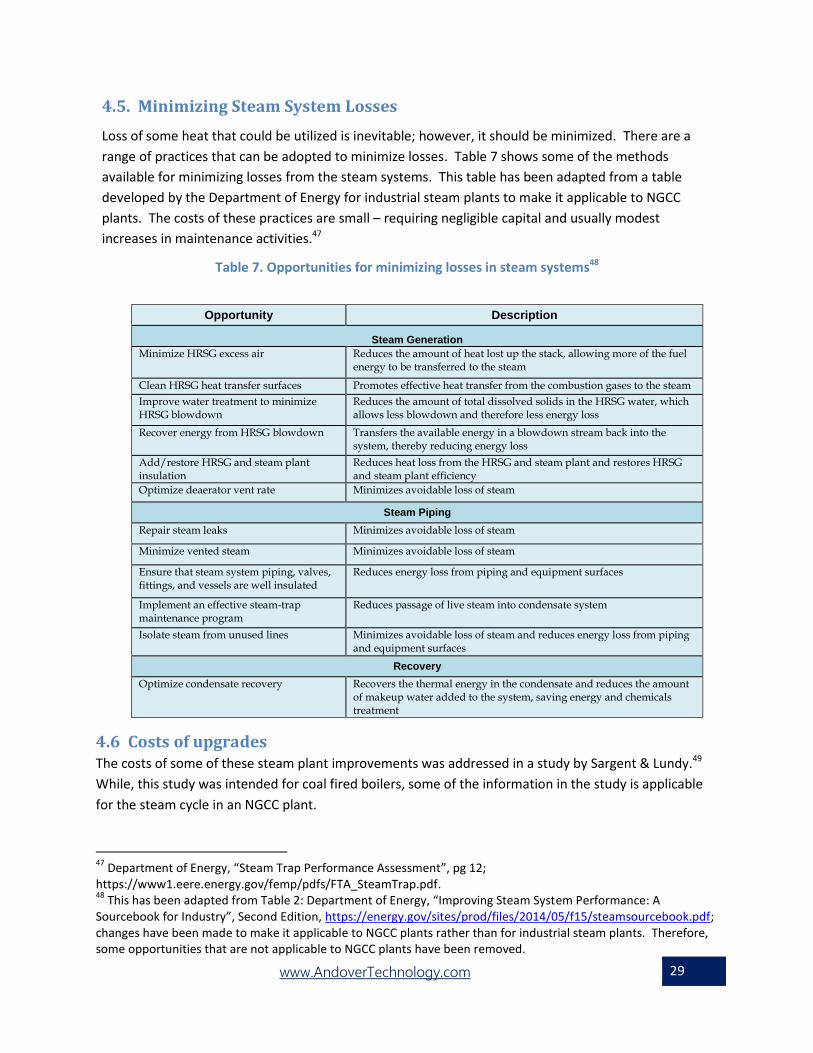
4.5. Minimizing Steam System Losses
Loss of some heat that could be utilized is inevitable; however, it should be minimized. There are a
range of practices that can be adopted to minimize losses. Table 7 shows some of the methods
available for minimizing losses from the steam systems. This table has been adapted from a table
developed by the Department of Energy for industrial steam plants to make it applicable to NGCC
plants. The costs of these practices are small – requiring negligible capital and usually modest
increases in maintenance activities.47
Table 7. Opportunities for minimizing losses in steam systems48
Opportunity Description
Steam Generation
Minimize HRSG excess air Reduces the amount of heat lost up the stack, allowing more of the fuel energy to be transferred to the steam
Clean HRSG heat transfer surfaces Promotes effective heat transfer from the combustion gases to the steam
Improve water treatment to minimize HRSG blowdown
Reduces the amount of total dissolved solids in the HRSG water, which allows less blowdown and therefore less energy loss
Recover energy from HRSG blowdown Transfers the available energy in a blowdown stream back into the system, thereby reducing energy loss
Add/restore HRSG and steam plant insulation
Reduces heat loss from the HRSG and steam plant and restores HRSG and steam plant efficiency
Optimize deaerator vent rate Minimizes avoidable loss of steam
Steam Piping
Repair steam leaks Minimizes avoidable loss of steam
Minimize vented steam Minimizes avoidable loss of steam
Ensure that steam system piping, valves, fittings, and vessels are well insulated
Reduces energy loss from piping and equipment surfaces
Implement an effective steam-trap maintenance program
Reduces passage of live steam into condensate system
Isolate steam from unused lines Minimizes avoidable loss of steam and reduces energy loss from piping and equipment surfaces
Recovery
Optimize condensate recovery Recovers the thermal energy in the condensate and reduces the amount of makeup water added to the system, saving energy and chemicals treatment
4.6 Costs of upgrades The costs of some of these steam plant improvements was addressed in a study by Sargent & Lundy.49
While, this study was intended for coal fired boilers, some of the information in the study is applicable
for the steam cycle in an NGCC plant.
47
Department of Energy, “Steam Trap Performance Assessment”, pg 12; https://www1.eere.energy.gov/femp/pdfs/FTA_SteamTrap.pdf. 48
This has been adapted from Table 2: Department of Energy, “Improving Steam System Performance: A Sourcebook for Industry”, Second Edition, https://energy.gov/sites/prod/files/2014/05/f15/steamsourcebook.pdf; changes have been made to make it applicable to NGCC plants rather than for industrial steam plants. Therefore, some opportunities that are not applicable to NGCC plants have been removed.

www.AndoverTechnology.com 30
The Sargent & Lundy study found that the cost of a turbine overhaul was in the range of $2-$12 million
for a 200 MW turbine and could provide a heat rate improvement in the range of 100-300 Btu/kWh
(about 1-3% for the steam cycle). Condenser heat rate reductions for a 200 MW steam cycle could be in
the range of 30-70 Btu/kWh or around 0.3-0.7% of the steam cycle heat rate at an O&M cost of
$30,000/year. Feed pump rebuilds for a 200 MW steam plant cost in the range of $250.000-$350,00050
and provide roughly 0.25%-0.50% improvement in steam cycle heat rate.
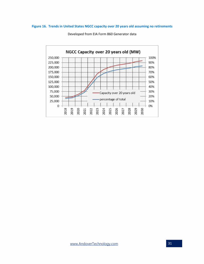
5.0 The opportunity for gas and steam turbine upgrades
Sections 3 and 4 described the various improvements that may be possible for NGCC plant gas or steam
turbine systems. Currently, there are over 43,000 MW of NGCC capacity (16% of the current total) that
is 20 years old or older. If there are no retirements, this will increase to over 167,000 MW of NGCC
capacity (59% of the current total) within 5 years and over 200,000 MW (over 70% of the current total)
by 2025. Therefore, we will soon be at a point in time when most of the currently installed NGCC plants
will be in excess of 20 years old. Figure 16 shows the trend in NGCC capacity over 20 years old assuming
no retirements. As such, there is likely a large portion of this capacity that can have its heat rate
improved through gas turbine or steam turbine upgrades. As noted in Section 3, comprehensive gas
turbine upgrades can improve heat rate up to 5% for the turbine, or roughly 3% of the total NGCC
capacity. This also comes with an increase in output that might range from about 5% to over 20%
(simple cycle) or 3% to over 12% (combined cycle). As noted in Figure 15, at 20 years the average steam
turbine improvement is roughly 8% or about 3.2% of total NGCC capacity. This does not include
improvements possible through TIC, dispatching of TIC over firing of duct burners, or from other steam
plant improvements. Thus, after 20 years of operation there could be on the order of 6% or more
improvement in heat rate through improvements in the gas turbine and steam system plus the
additional improvements possible through TIC. This will vary from one NGCC plant to another
depending upon specific circumstances. In any event, there are substantial improvements in heat rate
possible for NGCC plants.
49
Sargent & Lundy, “COAL-FIRED POWER PLANT HEAT RATE REDUCTIONS”, SL-009597 FINAL REPORT JANUARY 22, 2009 PROJECT 12301-001 50
Costs are in 2008 dollars
www.AndoverTechnology.com 31
Figure 16. Trends in United States NGCC capacity over 20 years old assuming no retirements
Developed from EIA Form 860 Generator data