Embed Size (px)
Citation preview

7/24/2014
1
IMPT Delivery Systems and
Current Limitations
Lei Dong, PhD Scripps Proton Therapy Center
San Diego, California
AAPM Symposium
July, 2014
Disclosure
Varian’s ProBeam user
Goals
To learn about typical components of
IMPT delivery system
To understand various potential limitations
in treatment delivery and treatment
planning
7/24/2014
2
4
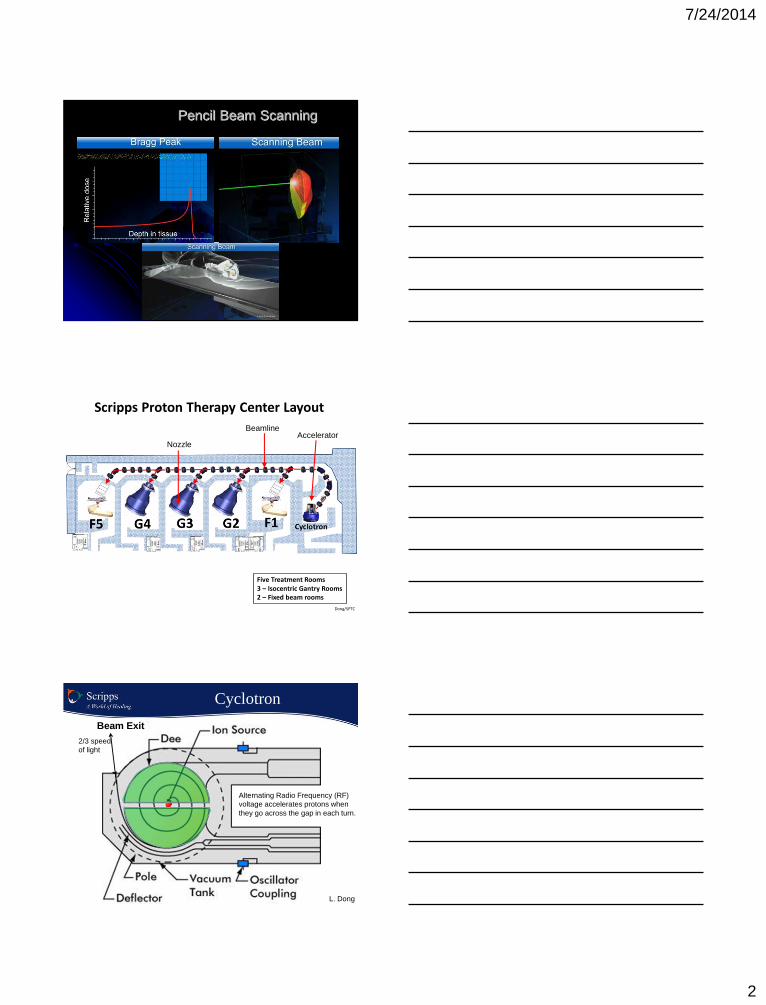
Pencil Beam Scanning
Scripps Proton Therapy Center Layout
Five Treatment Rooms 3 – Isocentric Gantry Rooms 2 – Fixed beam rooms
Dong/SPTC
Accelerator Beamline
Nozzle
Cyclotron
Beam Exit
Alternating Radio Frequency (RF)
voltage accelerates protons when
they go across the gap in each turn.
2/3 speed
of light
L. Dong
7/24/2014
3
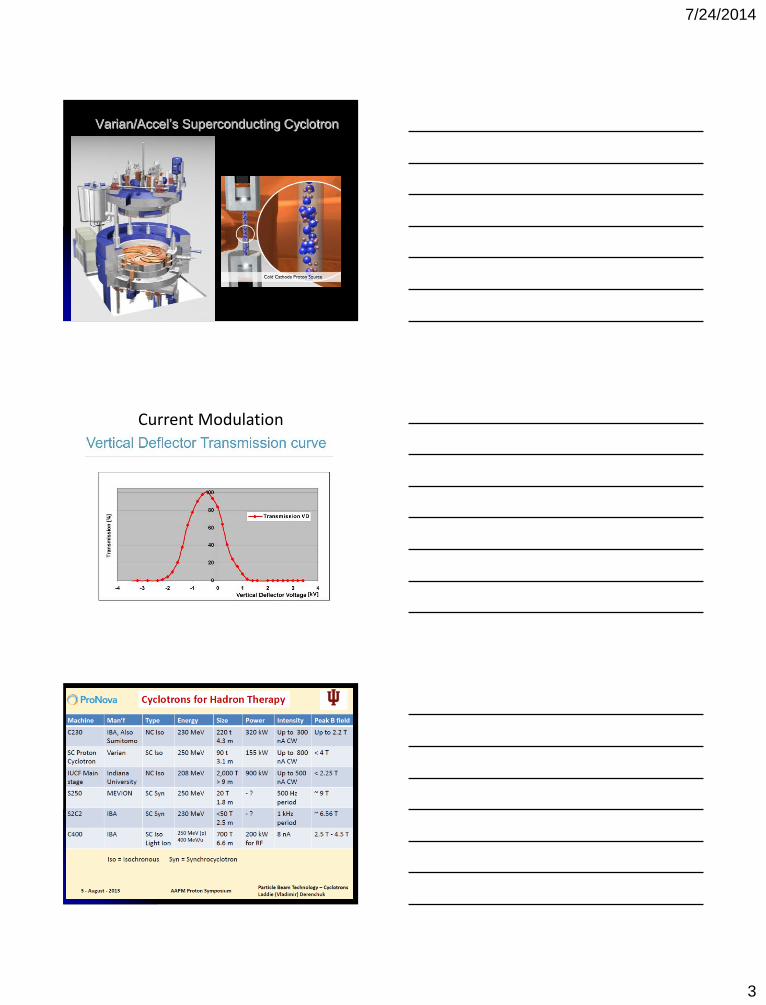
Varian/Accel’s Superconducting Cyclotron
Current Modulation

7/24/2014
4
PTC-H 250 MeV
Synchrotron Ring
Scanning beam timing chart
Smith et al. Med Phys 2009
7/24/2014
5
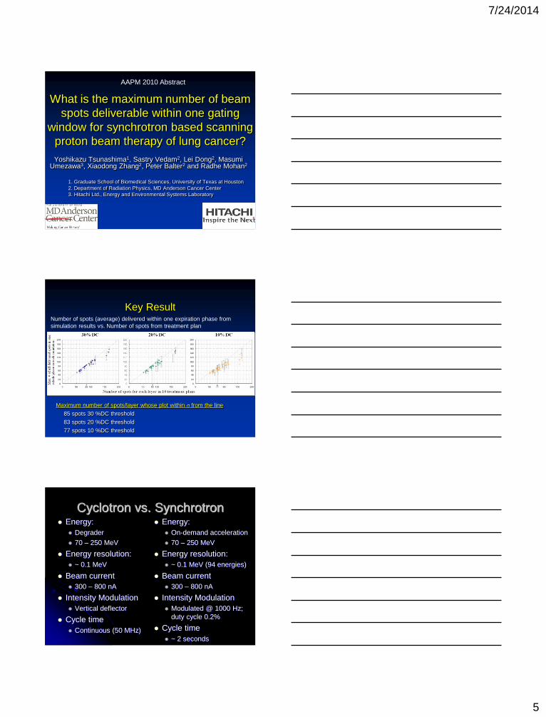
Yoshikazu Tsunashima1, Sastry Vedam2, Lei Dong2, Masumi Umezawa3, Xiaodong Zhang2, Peter Balter2 and Radhe Mohan2
1. Graduate School of Biomedical Sciences, University of Texas at Houston
2. Department of Radiation Physics, MD Anderson Cancer Center
3. Hitachi Ltd., Energy and Environmental Systems Laboratory
What is the maximum number of beam
spots deliverable within one gating
window for synchrotron based scanning
proton beam therapy of lung cancer?
AAPM 2010 Abstract
Key Result Number of spots (average) delivered within one expiration phase from
simulation results vs. Number of spots from treatment plan
Maximum number of spots/layer whose plot within σ from the line
85 spots 30 %DC threshold
83 spots 20 %DC threshold
77 spots 10 %DC threshold
Number of spots
Cyclotron vs. Synchrotron Energy:
Degrader
70 – 250 MeV
Energy resolution:
~ 0.1 MeV
Beam current
300 – 800 nA
Intensity Modulation
Vertical deflector
Cycle time
Continuous (50 MHz)
Energy:
On-demand acceleration
70 – 250 MeV
Energy resolution:
~ 0.1 MeV (94 energies)
Beam current
300 – 800 nA
Intensity Modulation
Modulated @ 1000 Hz;
duty cycle 0.2%
Cycle time
~ 2 seconds

7/24/2014
6
16
Beam Steering by Magnetic Fields
• Dipoles: for bending
the beam
• Quadruples: focusing
the beam
• Vacuum pumps to keep
beamline under very
high level of vacuum
(think about outer
space)
• Beam profile monitors
to measure beam along
the central tube Dipoles
Quadruples
17
Beamline
Changing Field Strength and
Managing Residual Magnetic Field

7/24/2014
7
Beam Delivery System Nozzle
Lateral scanning system
Position monitoring system
Dose monitoring system
Accessory holders (range shifter and aperture)
Imaging (optional)
Scanning System Challenges Power requirements
Faster scans and large fields require high
power (>1000A)
Raster vs. Spot Scanning
High precision is required for magnetic
field
Gantry dependence
Position monitoring at low dose rate
Preferred fast scan direction to minimize
breathing motion
Med. Phys. 36 (8), 2009
Variations in proton scanned beam dose delivery due to uncertainties in
magnetic beam steering
Stephen Peterson and Jerimy Polf et al.
Variations in
Magnetic field
Strength ∆B
Displacement of
spot lateral
positions: ∆s
Dose delivery
Uncertainties
in Patient: ∆D
Analytical Empirical

7/24/2014
8
Variations in magnetic field strength leads
to fluctuations in the steering of the pencil
beams to their intended final position.
Analytical formula between magnet strength and lateral spot position
Magnetic steering beam position relationship: physics Y-direction magnet Find the function mapping magnet
strength to beam position:
Lorentz and centripetal force:
Relativity effect:
Relativistic mass:
Results
7/24/2014
9
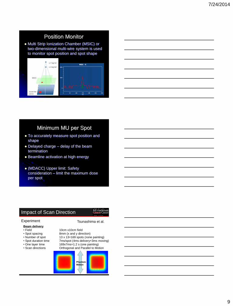
Position Monitor
Multi Strip Ionization Chamber (MSIC) or
two-dimensional multi-wire system is used
to monitor spot position and spot shape
Minimum MU per Spot
To accurately measure spot position and
shape
Delayed charge – delay of the beam
termination
Beamline activation at high energy
(MDACC) Upper limit: Safety
consideration – limit the maximum dose
per spot
Impact of Scan Direction
Experiment
Beam delivery
• Field 10cm x10cm field
• Spot spacing 8mm (x and y direction)
• Number of spot 13 x 13=169 spots (≡one painting)
• Spot duration time 7ms/spot (4ms delivery+3ms moving)
• One layer time 169x7ms=1.2 s (one painting)
• Scan directions Orthogonal and Parallel to Motion
Phantom
Motion
Tsunashima et al.

7/24/2014
10
Results
Reference:
10x10 cm2 field
Spot spacing 8mm
169 spots
1.18 s for delivery
No repainting
T=3 s
Painting x1
T=3 s
Painting x2
T=3 s
Painting x4
Orthogonal scan
A=3mm A=5mm A=10mm A=20mm
A=3mm A=5mm A=10mm A=20mm
Phase+
Phase-
Phase+
Phase-
Phase+
Phase-
Phantom motion
Tsunashima et al.
Results
Reference:
10x10 cm2 field
Spot spacing 8mm
169 spots
1.18 s for delivery
No repainting
Phase+
Phase-
Phase+
Phase-
Phase+
Phase-
T=3 s
Painting x1
T=3 s
Painting x2
T=3 s
Painting x4
A=3mm A=5mm A=10mm A=20mm
A=3mm A=5mm A=10mm A=20mm
Parallel scan
Phantom motion
Tsunashima et al.
Spot Size Issue
7/24/2014
11
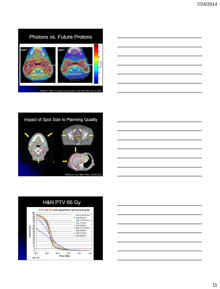
Photons vs. Future Protons
Bortfeld T. IMRT: “A review and a preview”, Phys. Med. Biol. 51(13), 2006.
Impact of Spot Size to Planning Quality
Widesott et al. Med. Phys. 39 (3) 2012
H&N PTV 66 Gy

7/24/2014
12
Conclusions
Summary:
Why is PBS Possible Today?
• Better power supply for magnets (dipole;
quadruple; fast scanning coils)
• More advanced accelerator technology
– More efficient accelerator
– Better beam optics (smaller spots)
– Fast energy change and current modulation
– Automatic beam tuning and control system
– Better and faster electronic circuits
LD 04/13