Embed Size (px)
Citation preview

IMV1 on the Vortex Induced Vibrations of Flexible Flettner
Rotors
Literature Review
Student- Michael Gillway
Matriculation Number- S0929318
31/10/2013

1. Thesis Statement
This project will investigate the conditions at which vortex induced instabilities are present on a
flexibly supported, damped and rotating cylinder, which is allowed to pivot in the cross-flow
direction and has a controlled stiffness.
The intended outcome of these investigations will not only cover an area of research that has yet to
be studied by experimental and computational means, but will also be of benefit to the fields of fluid
mechanics and thrust generation.
2. Introduction
Section 3 of this report will present a brief review into the background surrounding the Flettner
rotor and its applications. A full account of the relevant literature surrounding this project will then
be given in section 4; this will aim to establish a theoretical framework for the topic, defining the
area of the study and identify the key findings in these areas. After doing so, the report will give an
overview to a selection of preliminary design considerations and the progress report (up to the time
of reporting).
3. Problem Formulation
Flettner rotors are spinning cylinders, which produce fluid dynamic lift using the Magnus Effect.
Anton Flettner- a German Aviation Engineer, used spinning cylinders for the first time as a ship’s
propulsion system in 1926 (Lantham et al, 2012). In this voyage, the new and lighter rotors which
replaced the previous sailing rig enabled the ship to break and turn around its own axis and to tack
closer to the wind than its original design (Salter et al, 2008). However, with limitations in rotor
bearing design (Salter et al, 2008), alongside the growth of the diesel engine and low fuel prices, the
development of flettner rotor was stemmed.
While these factors supressed the uses of the Flettner rotor in the early 20th century, the current
market conditions, as well as the growing need for carbon dioxide mitigation has led to the appliance
of Magnus technology across a range of sectors. This includes the Flettner ship itself, which has seen
recent developments in a number of projects (Craft, 2013). An example of a current Flettner ship is
the E-Ship 1, which was constructed in 2010 and is used by German wind turbine manufacturer
Enercon GmbH (Enercon, 2010). The vessel employs four rotors which rise from the ships main deck
and are used to power the ships propeller (Craft, 2013). Another poignant example is the proposed
construction of a fleet of unmanned and flettner propelled vessels by Salter et al (2008). It is
suggested that these vessels will utilise machine-cloud brightening technology to mitigate the effects
of global warming.
In addition to naval vessels, the magus effect has also been applied in the field of aeronautics. The
rotor plane is a historic example and is a case where rotating cylinders were used in place of the
traditional wing arrangement to provide the plane’s lifting force (Seifert, 2012). However, while
designs such as the Plymoth A-A-2004 were tested as early as 1920 (Spooner, 1924), the power
efficiency of the rotating cylinders were found to be lower than that of conventional wings (Seifert,
2012). Also, uncertainties into the structural strength of these systems meant the designs were
never put into production (Seifert, 2012).
Like the Flettner rotor, it was not until the late 20th century when the magus affect proved a useful
solution for aeronautical applications. One of these is the third YOV-10A prototype proposed by

Calderon (1961), which utilises Magnus technology on an aircraft to provide increased lift at low
flying speeds. Further to the YOV-10A, rotating cylinders have also made their way into in the field of
moving surface boundary layer control (MSBC) and have been implemented in aerofoil design
concepts for flow control (Mittal, 2002). One example is the work of Modi (1990), who found that
substantial increases in lift, delays in stall and suppression of the vortex-induced oscillations could
be achieved by positioning rotating cylinders at the leading and/or trailing edge of the aerofoil.
While it can be seen that rotating cylinders have a range of applications in thrust generation,
Seifert’s review of the topic (Seifert 2012) concludes aeronautical applications to have numerous
limitations and uncertainties into their operational stability and efficiency under a range of
situations.
The reporting into Rotor ships tells a different story. The E-Ship 1 is in current use and has been
recounted to cover more than 17,000 sea miles through various waters and with no mention of
instability (Enercon, 2013). Similarly, over the six years of operation, the functionality and reliability
of the Flettner ship (named Babara) was proven and the rotors kept in good condition in adverse
weather conditions (Seifert, 2012).
Although these examples would support the stability of larger rotor ship designs, Barbara did
encounter small amounts of ship heeling (less than 50) in adverse conditions (Seifert, 2012) and
further to this, limited technical information can be accessed on the E-Ship 1. This topic was also
addressed in a recent study by Latham et al (2012), who highlighted the need for examination into
the effects of heeling on the aerodynamic performance of the Flettner rotor.
The present work- identified in section 1- attempts to give a greater insight into the stability of
rotating cylinders by experimental means and is expected to provide benefit to the engineering
issues highlighted above.
4. Review of Literature
Reid (1924) Prandtl (1925) and Thom (1926, 1932) were some of the first to measure the forces
present on a spinning cylinder (Mittal, 2002). These experimental investigations were particularly
concerned with the lifting characteristics of rotating cylinders and concluded that the mean lift of a
rotating cylinder was a function of its rotation rate (Tokumaru et al, 1993). However, while
informative, these initial efforts did not address how the flow characteristics changed as the cylinder
speed was increased and the effect this had on the stability of the spinning system.
In 1938, Goldstein (1938) published a study which showed that by increasing the circulation across
a stationary circular cylinder, a flow pattern develops where fixed streamlines surround the cylinder.
Following this discovery, a number of theoretical studies by Wood (1957), Moore (1957) and Glauert
(1957) investigated the effect of circulation on rotating cylinders. These investigations were carried
out for cases when the ratio of the surface speed of the cylinder to the free stream-speed of the fluid
(termed α) was α=0. Wood, 1957, Moore, 1957, and Glauert 1957 all concluded that the rotation of
the cylinder generated a circulation which was sufficient to delay flow separation for both finite and
infinite (invicid) Reynolds flows. More so, the results of Wood, 1957, Moore, 1957, and Glauert
(1957) showed that with a high enough value of α, it is possible supress vortex shedding across the
cylinder.
Within his initial research, Prandtl (1925) had proposed that the maximum circulation which could
be realised about a rotating cylinder was equal to the circulation at which the upstream and
downstream stagnation points joined (Tokumaru et al, 1993). From this analysis, he argued that the

maximum value of the steady-state lift coefficient was a finite value of 4π (~12.6) in uniform flow.
Prandtl’s proposal (1925) had obvious implications to applications using rotating cylinders for
thrust generation. For this reason, a series of further investigations then aimed to examine the
following two questions; if this was in fact the maximum value attainable by a rotating cylinder, and
also, if the rotation of the cylinder can supress vortex shedding across range of α values.
For cylinders rotating at α values between 0≤ α ≤ 1, Badr (1989), Dennis (1989) and Young (1989)
confirmed that cylinder’s rotation could suppress flow separation, however, each study found
differences in the lift and drag coefficients. In addition, Glauert (1957) also found that Prantl’s limit
could be exceeded and argued that the circulation across the rotating cylinders increased
indefinitely with α.
Coutanceau and Menard (1985) experimentally investigated the problem of unsteady flows across
rotating cylinders for Re=100, 500 and 1000 and 0.5≤ α ≤ 3.25. Past a critical α value (termed ) of
approximately 2 and independent of Re, Coutanceau and Menard (1985) found that only one vortex
was shed. This is supported by the computations from Badr and Dennis (1985) and the experimental
results of Diaz et al (1983) who found that periodic vortices dissipate after a rotational rate of α=2 is
reached.
To investigate if the proposed by Coutanceau and Menard (1985) was true for higher Reynolds
flows, an experimental and theoretical study was conducted by Badr et al (1990). This considered
flows between 103<Re<104 and over a short time period of less than 22 seconds. Agreeing with the
work of Coutanceau and Menard (1985), Badr et al (1990) found periodic vortex shedding to stop
past a value of α=2. Further to this, Badr et al (1990) defined a steady region between the limits of
2<α<3, where vortex suppression was apparent. However, when a value of α=3 was reached, Badr
et al (1990) found that three-dimensional flow effects resulted in vortex formation, and the
experimental flow transitioned to turbulent.
With the experiments of Badr et al (1990) showing vortex suppression due to α, Glauert’s (1957)
proposal that circulation increases indefinitely with α, and the obvious advantages of higher lift
generation, the question of Prandtl’s maximum lift was still of interest- as was the flow stability at
higher α values.
Following the findings of Badr et al (1990); Tokumaru and Dimotakis (1993) devised a method to
estimate the mean lift acting on a rotating cylinder in a uniform flow. At Re=3.8x10³ and 0<α<2.1,
Tokumaru and Dimotakis (1993) argued that Prandtl’s limit on the lift coefficient could be exceeded
by more than 20% when α=10. Tokumaru and Dimotakis (1993) claimed that Prandl had neglected
the three-dimensional effects of unsteady flow. The computations of Chen et al (1993) also found an
instantaneous lift coefficient greater than Prandtl’s predictions at α=3.25 and Re=200.
However, while these results suggested that more lift could be realised with greater rotational
speeds, not all results disagreed with that of Prandtl’s. The 2-dimensional analysis of Chew et al
(1995) reported results in agreement with Prandtl’s limit. With some dispute in this topic, the
subject of maximum lift would not be reprised till the later studies of Mittal (2002, 2004).
Following the three-dimensional effects seen in the high Reynolds flow study (Re=3.8x10³) of
Tokumaru and Dimotakis (1993); Chang and Chern (1991) examined 103≤ Re ≤ 106 over the
rotational rate of 0≤ α ≤ 2, and across time period of 12 seconds. This study reported vortex
shedding, showing the shedding patterns to be clearly related to the time variation in the lift
coefficients (Chang and Chern, 1991). This opened the discussion of time variations in flow.

To investigate flows over time periods of t ≤ 22 Chen et al (1993) computationally studied 0.5≤ α ≤
3.25 at Re=200, finding vortex shedding at α=3.25. The numerical simulations of Kang and Choi
(1999) computed flow for up to 100s and found to have logarithmic dependence with Re for 60≤
Re ≤ 160.
In an effort to resolve these issues with maximum lift, stability and time dependencies, Mittal and
Kumar (2002) presented the computed between 0≤ α≤ 5, at Re=200 and over time periods up to
300s. Between 0≤ α≤ 5, Mittal and Kumar (2004) observed vortex shedding below α≤1.91 and
steady state conditions outside of 4.34≤ α ≤ 4.7. These results were in exact agreement with the
value =1.91 proposed by Degnai et al (1998) for unsteady and invicid flows. Mittal and Kumar
(2004) concluded that Chen et al (1993) had ceased to allow sufficient time for the flow to achieve
steady state. Figure 1 presents the comparison between the different measured and calculated
coefficients of lift found between the main studies presented. Figure 2 shows the time history of the
measurements taken of the coefficient of lift by Chen et al (1993) and Mittal and Kumar (2002).
Figure 1: A Comparison between the measured and calculated lift and drag coefficients for spinning cylinders (Salter et al, 2008)
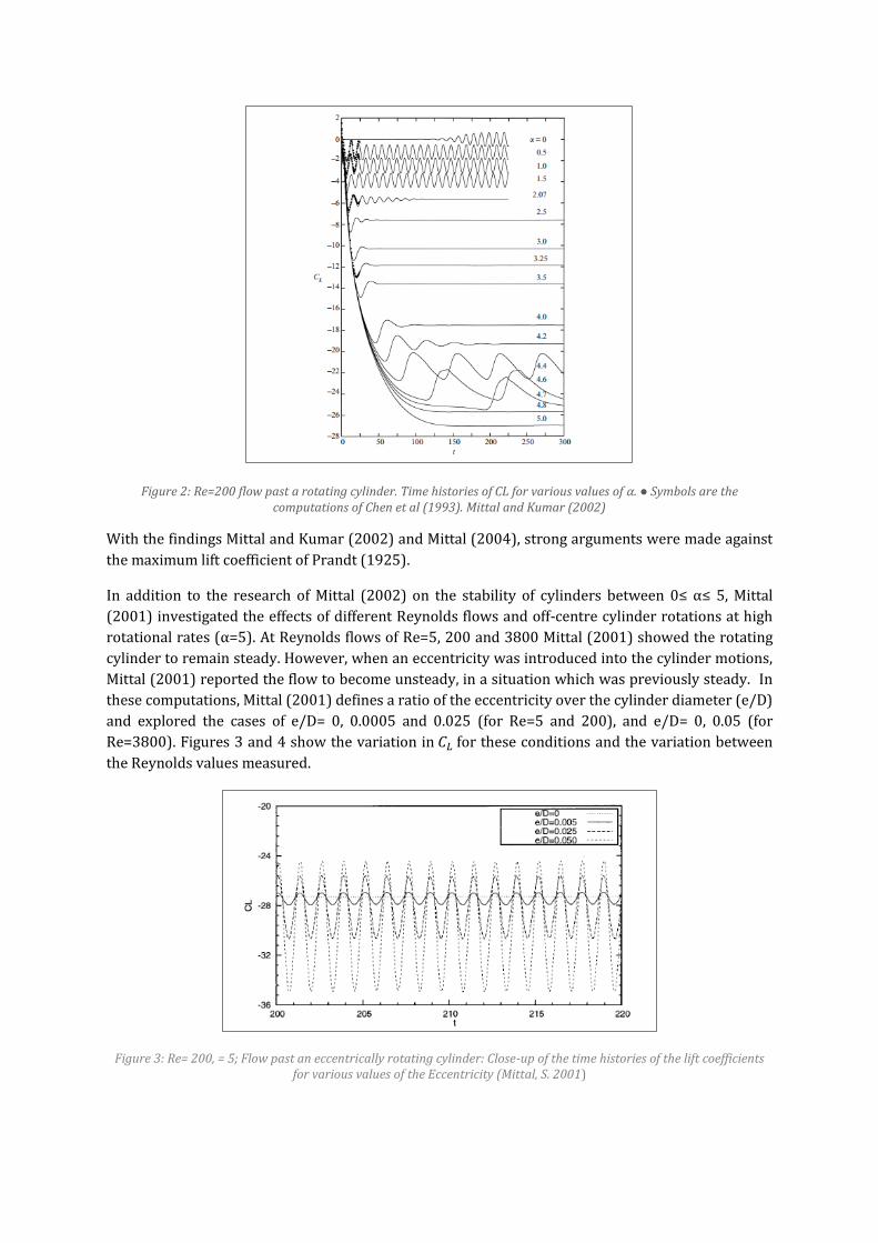
Figure 2: Re=200 flow past a rotating cylinder. Time histories of CL for various values of α. ● Symbols are the computations of Chen et al (1993). Mittal and Kumar (2002)
With the findings Mittal and Kumar (2002) and Mittal (2004), strong arguments were made against
the maximum lift coefficient of Prandt (1925).
In addition to the research of Mittal (2002) on the stability of cylinders between 0≤ α≤ 5, Mittal
(2001) investigated the effects of different Reynolds flows and off-centre cylinder rotations at high
rotational rates (α=5). At Reynolds flows of Re=5, 200 and 3800 Mittal (2001) showed the rotating
cylinder to remain steady. However, when an eccentricity was introduced into the cylinder motions,
Mittal (2001) reported the flow to become unsteady, in a situation which was previously steady. In
these computations, Mittal (2001) defines a ratio of the eccentricity over the cylinder diameter (e/D)
and explored the cases of e/D= 0, 0.0005 and 0.025 (for Re=5 and 200), and e/D= 0, 0.05 (for
Re=3800). Figures 3 and 4 show the variation in for these conditions and the variation between
the Reynolds values measured.
Figure 3: Re= 200, = 5; Flow past an eccentrically rotating cylinder: Close-up of the time histories of the lift coefficients for various values of the Eccentricity (Mittal, S. 2001)

Figure 4: Re=200, 3800, e=0.005D; flow past an eccentrically rotating cylinder: time-histories of the lift coefficients
After finding that the effects of eccentricity influence the dimensional characteristics of the flow
(Mittal, 2001), Mittal (2004) used three dimensional computations to further investigated the nature
of dimensional instabilities at α=5 and Re=200. These computations found centrifugal instabilities to
exist across the cylinder span, which were not present in the 2 dimensional results (Mittal, 2004).
Up to this point, the literature reviewed has assumed the rotating cylinder to possess infinite
stiffness and the Reynolds numbers used have been far below those expected from real engineering
situations. This is highlighted by Latham et al (2012), who states that a major question in the field of
rotating cylinders is whether or not the flow is stable for the α≤5 when Reynolds numbers
characteristic of the Flettner rotors (Re≈ 106) are used. This study also re-iterates the need for
examination into more realistic effects of heeling on the aerodynamic performance of the Flettner
rotor. This is supported by the work of Mittal and Kumar (2001), who simulated a lightly damped
and flexibly supported (non-rotating) cylinder, which allowed motion in line and in the cross flow
directions and with 103≤Re≤104. These two-dimensional investigations, found the flexible motions
to alter the fluid flow significantly. Furthermore, Mittal and kumar (2001) found that the fluid
interaction was dependant on the Reynolds number- with higher Reynolds flows (Re=104)
producing a more disorganised wake (Mittal and Kumar, 2001).
The research by Stansby (2000) also re-iterates the need for investigations on damped rotating
cylinders with a controlled stiffness. Stansby (2000) conducted a 2 dimensional analysis to
investigated the dynamic response of a damped rotating cylinder in a fluid steam, with a damping
ratio of ζ= 1.59x10 -3. α was varied between 0≤ α ≤ 0.3 in a low Reynolds flow (Re=200), finding that
at α = 0.3 a rapidly changing wake structure produced amplitudes of several diameters.
5. Design of Experiments
While the main apparatus is still within the design phase, this section will discuss the three
experimental and design considerations in relation to the rotating cylinder. These are; the aspect
ratio (AR) of the cylinder, the end conditions of the cylinder and the α range chosen.
End plates have been chosen for the final cylinder design, and should time permit, the experiments
will be repeated with these plates removed. Further to this, the cylinder used will have a wetted (or
apparent) aspect ratio of greater than 5 within the fluid and as close to AR=15 as the apparatus will
allow. The research of Tokumaru and Dimoakis (1993) reported the lift coefficient to have a strong

dependence on the aspect ratio (spanwise length/diameter) and the cylinder end conditions. This
was confirmed in the investigations of Mittal (2000 and 2004), which concluded that the cylinder
end conditions contribute to centrifugal instabilities along the cylinder, and can be
eliminated/minimised with the use of an end plates and a very large AR. This was also found by
Slaouti and Gerrard (1981), who studied the vortex shedding dependency on the end conditions of
cylinders for 25≤ AR ≤ 30 and 60≤ Re ≤ 200. Mittal (2004) suggests that at values of AR=5, losses in
suction seen. For an AR=15 Mittal (2004) states that the flow produced may be close to two-
dimensional flows. In addition to this, the results of Mittal (2000) for Re=190-250 and small AR’s
(Unspecified AR value) are found to extend/delay the known wake transition regime.
The experiment will be conducted between the ranges of 2≤α ≤4. It has been shown that numerous
of investigations have studied the flow around cylinders in conditions where α ≤3.25 (Mittal, 2002).
The more recent studies of Mittal (2004), Lathem et al (2013) and others have then explored higher
α values up to α=5. To the knowledge of author, this will be the first study to explore 2≤α ≤4 with a
flexibly supported, damped and rotating cylinder, which is allowed to pivot in the cross-flow
direction and has a controlled stiffness.
6. Progress Report
The progress of the project up to the date of the literature review submission is shown in a Gantt
within the appendix. As Figure N shows, at the time of reporting, the project is currently designing
the experimental apparatus, which will be built in house and will be used to conduct the experiment.
Figure 5 in the appendix shows a hand sketch of the proposed design. The rig will be positioned on
top of the Edinburgh University wave flume, which has been selected for the study. A preliminary
aim of the project has been set to develop the finished rig design by the end of November 2013.
Testing will then commence in Febuary of 2014.

7. References
Badr, H.M, Coutanceau, M., Dennis, S.C.R & Menard, C. 1990. Unsteady Flow Past a Rotating Circular
Cylinder at Reynolds Numbers 103 and 104. J. Fluid Mech. 220, 459-484.
Badr, H.M & Dennis, S.C.R. 1985. Time-dependant Viscous Flow Past an Impulsively Started Rotating
and Translating Circular Cylinder. J. Fluid mech. 158, 447-488
Badr, H.M and Dennis, S.C.R. 1989. Steady and Unsteady Flow Past a Rotating Circular Cylinder at
Low Reynolds Numbers. Computer Fluids 17, 579-609.
Calderon, A.A. & Arnold FR.1961. A Study of the Aerodynamic Characteristics of a High Lift Device
Based on the Rotating Cylinder and Flap. [Technical Report RCF-1]. Stanford University.
Chang, C. C. & Chern, R.L 1991. Vortex Shedding From an Impulsively Started Rotating and
Translating Circular Cylinder. J. Fluid Mech, 233, 265-298
Chen, Yen-Ming. Ou, Yu-Roung & Pearlstein, A. J., 1993, Development of the Wake Behind A Circular
Cylinder Impulsively Started Into Rotary and Rectilinear Motion. J. Fluid Mech, 253. 449–484.
Chew, Y. T., Cheng, M. & Luo, S. C. 1995. A Numerical Study of Fow Past a Rotating Circular Cylinder
Using a Hybrid Vortex Scheme. J. Fluid Mech. 299, 35-71.
Coutanceau, M & Menard, C. 1985. Influence of Rotation on the Near-Wake Development Behind an
Impulsively Started Circular Cylinder. J. Fluid Mech. 158, 399-446.
Craft, T.J. et al. 2012. Back to the Future-Thom Rotors for Maritime Propulsion? Turbulence, Heat
Transfer and Mass Transfer 7. 1-2.
Craft, T. J, Iacovides. H. & launder B. 2013. Dynamic Performance of Flettner Rotors with and
Without Thom Disks. Turbulence Mechanics Group, School of MACE.
Degani, A. T., Walker, J. D. A. & Smith, F. T. 1998. Unsteady separation past moving surfaces. J. Fluid
Mech. 375, 1-38.
Diaz, F., Gavalda, J., Kawall, J. G., Keller, J. F. & Giralt, F. 1983 Vortex Shedding from a Spinning
Cylinder. Phys. Fluids 26, 3454-3460.
Enercon. 2010. Powered by Sailing Rotors: E-Ship 1 in the testing Phase. Enercon Magazine for Wind
Energy. Windblatt. 6-7.
Glauert, M.B 1957(a). The Flow Past a rapidly Rotating Circular Cylinder. Proc. R. Soc. London. A 242,
108-115.
Glauert, M.B 1957(b). A Boundary Layer Theorem with Applications to rotating Cylinders. Journal of
Fluid Mechanics. 2. 98-99.
Goldstein, S. 1938. Modern Developments in Fluid Dynamics. Clarendon.
Kang, S. & Choi, H. 1999. Laminar flow past a rotating cylinder. Phys. Fluids 11, 3312-3320
Prandtl, L. 1925. Die naturwissenschaften, vol. 13. 93-108. (English translation: Application of the
Magnus Effect to the Wind propulsion of Ships. NACA Tech Mem. 387, June 1926.

Latham, J et al 2012. Marine Cloud Brightening. Phil, trans. R. Soc. A. Volume 370. 4217-4262
Mittal, S. 2000. On the performance of High Aspect-Ratio Elements for Incompressible Flows.
Comput. Methods Appl. Eng., 199, 269-287.
Mittal, S. 2001. Flow Past Rotating Cylinder: Effect of Eccentricity. ASME J. App. Mech., 68. 543-552
Mittal, S. 2004. Three Dimensional Instabilities in Flow Past a Rotating Cylinder. January 2004.
Mittal & Kumar. 2001. Flow Induced Vibrations of a Light Circular Cylinder at Reynolds Numbers of
103 and 104. J Sound and Vibrations, 245, 923-946
Modi VJ, Mokhtarian F, Yokomizo T. 1990. Effect of Moving Surfaces on the Airfoil Boundary-layer
Control. Journal of Aircraft. 27(1):50, http://dx.doi.org/10.2514/3.45894
Moore, D.W. 1957. The Flow Past a Rapidly Rotating Cylinder in a Circular Stream. Journal of Fluid
Mechanics. 2. 541-550
Raid, E.G. 1924. Tests on Rotating Cylinders. NACA TN 209.
Salter, S. Sortino, G. Latham, J. 2008. Sea-going Hardware for the Cloud Albedo Method of Reversing
Global Warming. Phil. Trans. Royal Soc. A 336, 3989-4006
Seifert, J. 2012. A Review of the Magnus Effect in Aeronautics. Process in Aerospace Sciences 55
(2012) 17-45.
Spooner, S. 1924. The Rotor and Aviation. Flight- Aircraft and Airships November, 27th. 739-40
Slaouti and J. H. Gerrard. 1981. An Experimental Investigation of the End Effects on the Wake of a
Circular Cylinder Towed Through Water at Low Reynolds numbers, J. Fluid Mech. 112, 297 1981.
Thom, A.1926. The Pressure Round a Cylinder rotating in an Air Current. ARC R. & M
Thom, A.1931. Experiments on the Flow Past a Rotating Cylinder. ARC R. & M
Wood, W.W. 1957. Journal of Fluid Mechanics. 2, 77.

8. Appendix
Figure 5: Rough Sketch of Initial Design (Gillway, M. 2013)

09
/09
/20
13
16
/09
/20
13
23
/09
/20
13
30
/09
/20
13
07
/10
/20
13
14
/10
/20
13
21
/10
/20
13
28
/10
/20
13
Recap over Fluid Dynamics Courses for Background Knoledge
Background Research into Project Topics
Initial Meeting with Academic Staff
Start of Literature Review and Familiarisation with Bibliographic Websites
Preperation and Submission of Introductory Project Documents
Continued Review of Literature and Development of Draft
Initial Rig Design Proposals
Technical Meeting with Technical Laboritory Coordinator- D.Jardin
Weekly Meeting with Ignazio and Stephen- Review of Introductory Documents, Review of…
Continued Design of Rig
Background Reasding on Elecronic Control Systems and Electrical Power Engineering
Weekly Meeting with Ignazio- Review of Rig Design, Descussion on Thesis Aim
Development of Thesis Aim out of two Selected Options
Weekly Meeting with Ignazio and Stephen- Review of Rig Design, Clarificatio on Measurement…
Meeting with Electrionics Lab Work Coordinator
Design of Cylinder Stiffening System
Design of Motor gearing System
Weekly Meeting with Ignazio- Draft Literature Review Submission and Discussion
Final Preperation of Literature Review for Checking
Meeting with Technical Meeting with Stephen- Review Stiffening and Gearing Design
Meeting with Ignazio- Discussion on Final Literature Review Presentation
Final Literature Review Ammendments
Continued Rig Design- Calculate the Forces on the System, Continue Stiffening System Design
Hand in of Literature Review
Project Actions up to 30/10/13