Embed Size (px)
Citation preview

IN-7700
600 Volts & Below
VentilatedDry-Type
Transformers
Instruction Manual

2
Instructions for the Safe Handling, Installation, Operationand Maintenance of Ventilated Dry-Type Transformers
Table of ContentsParagraph Page
General ........................................................................................................................................ 1 ..................... 2Inspection upon Receipt .............................................................................................................. 2 ..................... 2Handling ....................................................................................................................................... 3 ................... 2-3Storage ........................................................................................................................................ 4 ..................... 3Application ................................................................................................................................... 5 ..................... 3Installation .................................................................................................................................... 6 ..................... 3
Accessibility ....................................................................................................................... 6.1 ................... 3Ventilation .......................................................................................................................... 6.2 ................... 3Sound ................................................................................................................................. 6.3 ................... 3Environmental Conditions .................................................................................................. 6.4 ................... 4Outdoor Installation ............................................................................................................ 6.5 ................... 4
Connections ................................................................................................................................. 7 ..................... 4Lighting Tap Applications ................................................................................................... 7.1 ................... 4Grounding .......................................................................................................................... 7.2 ................... 4
Before Energizing ........................................................................................................................ 8 ..................... 4Operation ..................................................................................................................................... 9 ................... 4-5Maintenance ............................................................................................................................... 10 .................... 5Drying ...........................................................................................................................................11 .................... 5
IMPORTANT: The information containedherein is general in nature and is notintended for specific application purposesnor is it intended as a training manual forunqualified personnel. It does not relievethe user of responsibility to use soundpractices in application, installation,
operation and maintenance of theequipment purchased or in personnel safetyprecautions. Should a conflict arisebetween the general information containedin this publication and the contents ofdrawings or supplementary material or both,the latter shall take precedence.
1. GeneralThe successful and safe operation of dry-typetransformers is dependent upon proper handling,installation, and maintenance. Neglecting certainfundamental installation and maintenance requirementsmay lead to personal injury and the failure and loss ofthe transformer as well as damage to other property.WARNING: DANGER! There is a hazard ofelectric shock or burn whenever working in oraround electrical equipment. Power must beoff before working inside a transformer.
Each transformer is assembled and given complete testsat the factory, after which it is inspected and packed forshipment.Units designed per Figure 2 are NEMA Type 2construction and are converted to NEMA Type 3R witha weathershield conversion kit.
2. Inspection Upon ReceiptImmediately upon receipt of the shipment, identify allunits and check them against the shipping list. Make avisual examination to detect any damage which mayhave been incurred during transit.If any damage is discovered, file a claim immediatelywith the carrier and send notice of the extent of damageto the local sales office, giving complete identification,carrier's name and railroad car number if the shipmentwas made by rail.The information will enable the company to supplynecessary data in support of claim.
3. HandlingAll transformers are bolted to a wooden skid forshipment. All units can be handled with a forklift truck.Transformers are provided with lifting eyes at the top ofthe enclosure for two point lift (see Figure 1) or at thebase for four point lift or by taking off the cover andusing the lifting means on the transformer. The useof a spreader is generally recommended. Units are

3
not designed for laying on their ends or sides. If it isnecessary to handle ventilated Dry-Type Transformersoutdoors during inclement weather, they should bethoroughly protected against the entrance of moisture.CAUTION: Never attempt to lift a transformer frompoints other than the lifting eyes provided.
4. StorageAny transformer which is not installed and energizedimmediately should be stored in a clean dry space havinga uniform temperature to prevent condensation.Preferably, it should be stored in a heated building havingadequate air circulation and protected from cement,plaster, paint, dirt and water. The protective plasticwrapping should be left in place during storage.
5. ApplicationInsulation systems are classified by industry standardsin accordance with the following rating system
These transformers are designed using a 220° Cinsulation system, regardless of the requestedtemperature rise of the transformer.Transformers with a standard 150° C windingtemperature rise operate at full load with a maximum50° C / 122° F temperature rise on the surface areas ofthe enclosure. As an example, with a 40° C ambient,the maximum measured enclosure surface temperaturewould be 90° C / 194° F.
6. InstallationDry-Type Transformers are for indoor use unless theenclosure is specifically designed for outdoor weather-proof service. They are cooled by means of freecirculation of air, the maximum ambient temperature ofwhich should not exceed 40° C (104° F). Damage mayresult if the air flow is restricted, or if the transformer isloaded beyond its rated capacity.Due to various building and room constructions, it isrecommended that applicable codes be followed.Factors which should be kept in mind when locating Dry-Type Transformers are: personnel safety, accessibility,ventilation, locations affecting sound level, andenvironmental conditions. Installations should be madein an area reasonably free from dust, moisture, chemicaland corrosive vapors or fumes. Dry-Type Transformersmust be installed in an upright position.CAUTION: Installation and maintenance should be
performed only by experienced and qualifiedpersonnel. No attempt should ever be made tochange the taps, or make cable connections whilethe transformer is energized. To maintain safeoperating conditions, do not remove the panels orcover while the transformer is in operation.
6.1 AccessibilityDry-Type Transformers should be located in an areawhere the transformer can be inspected at any time.The wiring compartment should be easily accessible atall times. It is a requirement of the National ElectricalCode that sufficient access and working space shall beprovided and maintained about all electrical equipmentto permit the ready and safe operation and maintenanceof such equipment. Refer to the requirements of theNEC for the particular installation involved.The working space required by this standard should notbe used as a passageway or for storage. When normallyenclosed live parts are exposed for inspection orservicing, the working space, if adjacent to apassageway or general open space where other workis carried on, should be guarded.
6.2 VentilationAdequate ventilation is essential for the proper coolingof Dry-Type Transformers and clean air is desirable.Filtered air may reduce maintenance if a locationpresents a particular problem.The ventilating screens and openings in the transformersare designed to provide adequate ventilation for thetransformer and should not be restricted in any way.Transformers rated through 51 KVA should be locatedat least 4 inches away from walls or other obstructionsto allow free circulation of air through the ventilationopenings. For units above 51 KVA, spacing should bea minimum of 6 inches. If the transformer is located in asmall room, ventilation should be provided to maintainan average of 30° C (86° F) ambient not to exceed 40°C (104° F) in any 24-hour period.
6.3 SoundAudible sound may be a factor, and consideration shouldbe given to the specific location and method ofinstallation of the transformer keeping in mind thefollowing suggestions:
• Mount the transformer away from corners of wallsor ceilings.
• Provide flexible conduit to make the connection tothe transformer.
• Use sound absorbing material on the walls andceiling.
• Locate the transformer as far as practical fromareas where high sound levels are undesirable.
Insulation Systems Classification Temp.
Ambient +Winding Rise +Hot Spot =Class
40° C 55° C 10° C 105° C40° C 80° C 30° C 150° C40° C 115° C 30° C 185° C40° C 150° C 30° C 220° C
4
6.4 Environmental ConditionsVentilated Dry-Type Transformers are normally designedfor installation in indoors applications only. They maybe installed outdoors if they are of outdoor construction.Outdoor construction may consist of specificallydesigned NEMA Type 3R enclosures or weathershieldconversion kits to convert indoor NEMA Type 2enclosures to NEMA Type 3R enclosures suitable forprotected outdoor installation. The transformernameplate specifies the proper weathershield kit to beused on the specific transformer. When this kit isproperly installed, the enclosure is listed by UL for NEMAType 3R protected outdoor installation.Transformers should be installed in locations where theambient atmosphere is free from unusual chemicalfumes or dust.
6.5 Outdoor InstallationThe same care must be taken when selecting a locationfor outdoor Dry-Type Transformers.Walls may be built around the transformer if proper careis taken to allow sufficient air flow. It is recommendedthat a suitable concrete pad with adequate drainage beused for the outdoor location. Pad should beapproximately 4" above ground level. The hole plugssupplied with some outdoor units must be in place ineach end of the unit to prevent moisture from enteringthe enclosure (Figure 1 and Figure 2).
CAUTION: Outdoor transformers are not tamperproof. The location of the transformer must be awayfrom children and all unauthorized personnel.Failure to do so may result in serious injury.
7. ConnectionsAll cable entrances should be into the terminalcompartment located in the lower transformer enclosure.When making cable connections or changing taps,always use two wrenches when tightening orloosening bolted connections to prevent distortionor damage. The terminal connections are either barealuminum, tin plated aluminum or copper. The aluminumsurfaces are furnished with a protective coating toprevent oxidation. The unused tap connections are alsofurnished with a protective coating. This coating shouldremain intact until these connection points are needed.
CAUTION: Make only those connections shown onthe nameplate or connection diagram. Beforeenergizing, check all tap jumpers for properlocations, and all bolted connections for tightness.
If it is necessary to change taps or assemble a lug to aconnection point, gently scrape coating from newconnection surface using a sharp knife. Apply a lightcoating of grease from the tap jumper pad to the scraped
surface and tighten connection using two wrenches asdescribed above. Refer to Figure 3, Page 8 forinstructions for the installation of cable lugs.Care must be taken to place all leads to the same load,or from the supply source through one knockout so thatno part of the transformer case is positioned betweensuch leads.
NOTE: After installation of connectors and cabling,a minimum of 1" clearance must be maintained fromenergized parts to all case parts.
7.1 Lighting Tap ApplicationsMost transformers with 240 volt delta secondaries havea 120 volt single-phase lighting tap. The maximumsingle-phase 120 volt load should not exceed 10% ofthe three-phase KVA rating. The load should also bebalanced at 5% maximum between terminals X1 to X4and 5% between terminals X2 to X4. The three-phaseKVA must also be reduced by 30% of the nameplaterating.
7.2 GroundingAll core and coil structures have a flexible groundconnection to the enclosure which ensures that all deadmetal parts have the same potential. The transformerenclosure should be solidly grounded so that no dangerwill exist for operating or maintenance personnel. Atransformer ground stud or ground bus is provided forthe customer's ground connections.The grounding conductor for a transformer should havea current-carrying capacity in accordance with theNational Electrical Code.
8. Before EnergizingBefore energizing the transformer, loosen or remove allshipping hardware, and store for future use. If it isdesired to change location of the transformer at a futuredate, reinstall all shipping hardware as shown in Figure1 and Figure 2. If shipping hardware is left in place,excessive enclosure vibration will increase the soundlevel.Check all tap jumpers for proper locations, and all boltedconnections for tightness, using two wrenches asdescribed in Section 7.After installation is completed, remove any debris fromthe bottom of the wiring compartment. Securely tightenall screws which hold the panels and covers in place toeliminate possible vibration of these parts.
9. OperationTo maintain safe operating conditions do not removepanels or covers over openings in the enclosure whilethe transformer is energized.

5
CAUTION: Never attempt to change taps orconnections unless the transformer is de-energizedand all windings grounded.
For all relatively clean and dry indoor installations, thetransformer will operate satisfactorily under normalconditions of energization and load. There is no concernover the transformer's ability to retain its electricalstrength during reasonable periods of shut down. Undersevere conditions and extended shutdown periodscondensation may form and ultimately be absorbed intothe insulation. If such a situation occurs, the transformershould be inspected for visible signs of moisture beforere-energizing. The transformer should be dried asspecified Section 11, "Drying" if moisture is visible.Transformers should not be overloaded for long periodsof time. The resulting temperatures can cause insulationdeterioration and transformer failure.If at any time evidence of overheating is noticed, externalfans (fans blowing on the outside of the enclosure orlouvers) must not be directed toward the transformer.This practice can result in mis-directed air flow whichcan retard or stop normal convection through thetransformer coil. As a result the transformer will furtheroverheat and failure may result in a short period of time.
10. MaintenanceUnder normal environments and operating conditions,Dry-Type Transformers are virtually maintenance free.However, they do require occasional external cleaning,repainting, internal cleaning, painting, and periodiccare and inspection. Where periodic inspection of anykind cannot be made, it should be recognized that thelife of the transformer may be affected.The frequency of inspection will depend on theatmospheric and/or environmental conditions at agiven transformer instal lat ion or locat ion. Atransformer may operate satisfactorily for many yearswithout attent ion but, under unusual serviceconditions, maintenance may be required in a matterof months.A continuously energized transformer needs periodicmaintenance only to remove accumulations of dustand dirt from cooling ducts and other surfaces. Largeaccumulations may reduce cooling efficiency and leadto overheating. The frequency of cleaning will dependon the environment in which the transformer is located.Cleaning is recommended at least once a year inrelatively clean installations and at more frequentintervals in more heavily contaminated atmospheres.Transformers which are de-energized for periods oftime generally require more frequent maintenance toinsure removal of contamination. Accumulation of dirton insulating surfaces becomes a hazard when aconsiderable amount of moisture is absorbed. It isalways advisable to clean any transformer suspectedof having been contaminated with dirt and moisture.Vacuuming is the recommended method for cleaning.Special attention should be given to cooling ductswithin the windings. Low pressure, dry air can beused if care is taken to avoid driving the contamination
deeper into insulations.When it is known that a transformer has been exposedto severe conditions of moisture, it should be cleanedand dried before energization.Maintenance must be done with the transformer ina de-energized condition. This would include suchthings as tap changing, internal inspection and cleaning,locating causes of faulty performance, replacing parts,etc. Corrective maintenance should be performed by aperson who is familiar with the construction andoperation of the apparatus and the hazards involved.In conducting corrective maintenance, such a personshould.:
• Be sure that the transformer is disconnectedfrom all electric power sources beforeservicing.
• After power has been disconnected from thetransformer, attach ground leads or theirequivalent to the input and output terminationsof the transformer. Such grounding may beunnecessary in the case of transformers that canbe visibly isolated from energized conductors byother disconnecting means.
• Inspect terminals for alignment, tightness,pressure, burns, or corrosion. Consult factory toreplace pitted or badly burned lugs.
• Inspect air ducts for the accumulation of dust andforeign substances; vacuum any accumulation.
• See that bolts, nuts, washers, pins, terminalconnectors, including ground connection, are inplace and in good condition.
11. DryingMoisture is detrimental to most insulation systems. Itis advisable to dry out any transformer which has beenexposed for long periods of high humidity. Whenevermoisture is visible on insulation surfaces, the unit mustbe dried before being energized.Drying may be accomplished by application of hot air,radiant heat or internal heat. Heated air should risethrough the windings. Heaters should be locatedbeneath the windings and elements should not beallowed to come in contact with the transformers. Heatshould be applied on both front and rear of thetransformer. The capacity of strip or space heatersrequired can generally be taken to be one-half wattfor each pound of transformer nameplate weight. Theapplication of heat should be maintained for aminimum of twenty-four hours after moisture is nolonger visible.Transformers may be subjected to flooding, direct rainor similar applications of water. In such cases, normaldrying techniques may not be adequate and thefactory should be consulted.Unfortunately, insulation resistance tests of the typeused on liquid filled transformers are of little value onDry-Type Transformers. The nature of insulation usedin Dry-Type Transformers is such that the megger andpower factor readings are not reliable and may bemisleading.
6
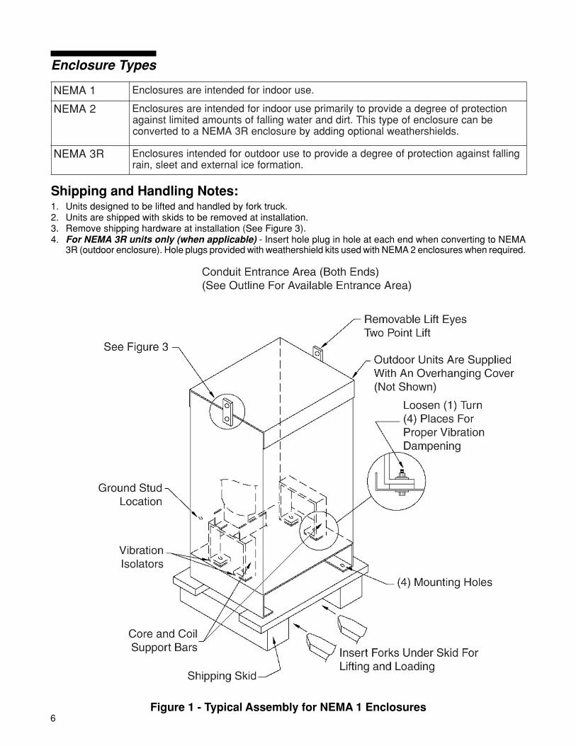
Enclosure Types
Figure 1 - Typical Assembly for NEMA 1 Enclosures
1AMEN .esuroodnirofdednetnieraserusolcnE
2AMEN noitcetorpfoeergedaedivorpotyliramirpesuroodnirofdednetnieraserusolcnEebnacerusolcnefoepytsihT.triddnaretawgnillaffostnuomadetimiltsniaga
.sdleihsrehtaewlanoitpogniddayberusolcneR3AMENaotdetrevnoc
R3AMEN gnillaftsniaganoitcetorpfoeergedaedivorpotesuroodtuorofdednetniserusolcnE.noitamrofecilanretxednateels,niar
1. Units designed to be lifted and handled by fork truck.2. Units are shipped with skids to be removed at installation.3. Remove shipping hardware at installation (See Figure 3).4. For NEMA 3R units only (when applicable) - Insert hole plug in hole at each end when converting to NEMA
3R (outdoor enclosure). Hole plugs provided with weathershield kits used with NEMA 2 enclosures when required.
Shipping and Handling Notes:
7
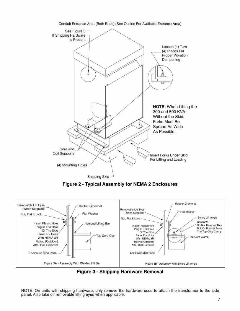
Figure 3 - Shipping Hardware Removal
NOTE: On units with shipping hardware, only remove the hardware used to attach the transformer to the sidepanel. Also take off removable lifting eyes when applicable.
Figure 2 - Typical Assembly for NEMA 2 Enclosures

8
Instructions for the Installation of Lugs
Notes:
1. See Paragraph 7, Page 4 for complete information on connections.2. When 2 or more lugs per phase are required, face half to the front and half to the rear.3. Caution: Always use two wrenches when tightening or loosening bolted connections to avoid damage or distortion
to the terminal.4. Do not install washers between the lug and terminal. This will cause heating and arcing, resulting in failure of
the connector.5. To ensure good electrical connections, the following torque values must be adhered to:
1/4 - 20 Bolt - 7 Foot Pounds3/8 - 16 Bolt - 20 Foot Pounds1/2 - 13 Bolt - 30 Foot Pounds
Figure 4
12/2001