Embed Size (px)
Citation preview

JA3664EN
MT4108EN
In-ChassisMaintenance
1000 And 2000Product Families

i
Allison Transmission
VOCATIONAL MODELS
In-ChassisMaintenance
2004 APRIL 01
JA3664EN
1000 EVS 2100 EVS 2200 EVS 2500 EVS1000 HS 2100 HS 2200 HS 2500 HS1000 MH 2100 MH 2200 MH 2500 MH1000 PTS 2100 PTS 2200 PTS 2500 PTS1000 RDS 2100 RDS 2200 RDS 2500 RDS1000 SP 2100 SP 2200 SP 2500 SPB 210 B 220
1000 Series™ 2000 Series™ 2000 MH Series 2400 Series™
Printed in USA Copyright © 2007 Allison Transmission, Inc.
Allison Transmission, Inc.
P.O. Box 894 Indianapolis, Indiana 46202-0894
www.allisontransmission.com

ii
TABLE OF CONTENTS
Paragraph Description Page
SECTION I TROUBLESHOOTING
1–1 General Troubleshooting Information . . . . . . . . . . . . . . . . . 11–2 General Troubleshooting of Performance Complaints . . . . 51–3 Transmission Stall Test And Neutral Cool-Down Check . . 241–4 Pressure Schedule Check . . . . . . . . . . . . . . . . . . . . . . . . . . . 26
SECTION II FLUID LEAK DIAGNOSIS
2–1 Finding the Leak . . . . . . . . . . . . . . . . . . . . . . . . . . . . . . . . . 27
SECTION III SHIFT SELECTOR AND CABLE/LINKAGE
3–1 Shift Selector and Cable/Linkage . . . . . . . . . . . . . . . . . . . . 303–2 Neutral Start/Backup (NSBU) Switch . . . . . . . . . . . . . . . . . 33
SECTION IV SELECTOR SHAFT SEAL REPLACEMENT
4–1 Removal . . . . . . . . . . . . . . . . . . . . . . . . . . . . . . . . . . . . . . . . 374–2 Installation . . . . . . . . . . . . . . . . . . . . . . . . . . . . . . . . . . . . . . 37
SECTION V PARKING BRAKE
5–1 Adjustment . . . . . . . . . . . . . . . . . . . . . . . . . . . . . . . . . . . . . . 405–2 Replacement . . . . . . . . . . . . . . . . . . . . . . . . . . . . . . . . . . . . . 405–3 Burnishing . . . . . . . . . . . . . . . . . . . . . . . . . . . . . . . . . . . . . . 42
SECTION VI COMPONENT REPLACEMENT
6–1 Output Flange/Yoke Replacement . . . . . . . . . . . . . . . . . . . . 436–2 Tachograph Plug Replacement . . . . . . . . . . . . . . . . . . . . . . 446–3 Speed Sensor Replacement . . . . . . . . . . . . . . . . . . . . . . . . . 446–4 PTO Cover/Gasket Replacement . . . . . . . . . . . . . . . . . . . . . 456–5 Cooler Manifold Gasket Replacement . . . . . . . . . . . . . . . . . 456–6 Rear Seal Replacement . . . . . . . . . . . . . . . . . . . . . . . . . . . . 486–7 Oil Pan Gasket Replacement . . . . . . . . . . . . . . . . . . . . . . . . 516–8 Suction Filter And Seal Replacement . . . . . . . . . . . . . . . . . 536–9 Control Valve Component Replacement . . . . . . . . . . . . . . . 546–10 Front Seal Replacement . . . . . . . . . . . . . . . . . . . . . . . . . . . . 686–11 Cooler Flushing . . . . . . . . . . . . . . . . . . . . . . . . . . . . . . . . . . 71
SECTION VII CUSTOMER SERVICE
7–1 Owner Assistance. . . . . . . . . . . . . . . . . . . . . . . . . . . . . . . . . 727–2 Service Literature . . . . . . . . . . . . . . . . . . . . . . . . . . . . . . . . . 72

iii
TRADEMARKS
1000 Series™ is a trademark of General Motors Corporation.
2000 Series™ is a trademark of General Motors Corporation.
2400 Series™ is a trademark of General Motors Corporation.
Allison DOC™ For PC is a trademark of General Motors Corporation.

iv
NOTES

1
1–1. GENERAL TROUBLESHOOTING INFORMATION
a. CHECK TRANS Light.
The
CHECK TRANS
light is original equipment manufacturer (OEM)-supplied and usually located on the vehicle’s instrument panel.
The
CHECK TRANS
light is illuminated briefly during vehicle start-up as a bulb check.
When the light is “ON” shifts may be restricted by the Transmission Control Module (TCM) when the TCM senses abnormal conditions as follows:
•
The transmission may be locked in the range it was in when the problem was detected.
•
The transmission may continue to operate with inhibited shifting.
•
The TCM may not respond to shift selector requests.
•
Direction changes and shifts from neutral-to-range may not occur.
NOTE:
The
CHECK ENGINE
light may serve the
CHECK TRANS
function for vehicles which are compliant to Industry On Board Diagnostics II (OBD-II) requirements.
WARNING:
If ignition is turned “OFF” and then “ON” while the
CHECK TRANS
light is displayed, the transmission may remain in neutral until the code is cleared. Leave ignition “ON” until you are in a safe place to stop.
TROUBLESHOOTING
S
ECTION
I

2
Whenever the
CHECK TRANS
light is displayed, the TCM logs a diagnostic code in memory. These diagnostic codes can be accessed through the Allison DOC™ For PC diagnostic system.
b. Range Inhibit Indicator.
If the TCM detects conditions such that a shift from Neutral to a forward range or to Reverse should not be allowed, shifts out of Neutral may be inhibited.
At the same time these events occur, a required OEM-supplied
RANGE INHIBITED
light, mounted on the dash or near the shift selector, is illuminated. This notifies the driver that shifting is inhibited and the shift selector may not respond to shifts requested.
c. Allison Diagnostic Optimized Connection™ (Allison DOC™ For PC).
Control system diagnostics are performed using a “Windows” PC operating system and interface/software which is available through Allison Transmission tool sources. The PC acts as a receiver/transmitter/display medium that allows the service technician to communicate with the TCM. Typical troubleshooting activities performed are installation checkout and diagnostic code retrieval.
Consult the User Guide which accompanies the Allison DOC™ For PC diagnostic tool. Figure 1–1 shows a typical beginning screen for the Allison DOC™ for PC diagnostic tool. The user’s manual contains the information for performing the following:
•
Displaying (retrieving) diagnostic trouble codes (DTCs) Transmission diagnostic codes begin with P0, P1, U1, or U2 followed immediately by three additional numbers. For a complete list of codes and more detailed information, refer to TS3192EN, Electronic Troubleshooting Manual.
•
Clearing diagnostic codes
•
Obtaining transmission data such as input speed or sump fluid temperature
•
Conducting solenoid testing
•
Conducting clutch diagnostics (including torque converter clutch)
NOTE:
Diagnostic codes can be logged without illuminating the
CHECK TRANS
light. This occurs when the TCM senses a problem, but determines the problem won’t cause immediate transmission damage or dangerous performance.

3
Figure 1–1. Trouble Code Screen—Allison DOC™ For PC
d. Troubleshooting When No Diagnostic Codes Are Present.
•
Always start with the basics:
— Make sure the shifter is in the appropriate range.
— Check the fluid level.
— Make sure batteries are properly connected and charged.

4
— Make sure throttle is closed and engine speed is below 900 rpm.
— Make sure electrical connections are properly made.
— Check support equipment for proper installation and operation.
•
If adaptive information had been reset, initial upshifts and downshift may be harsh. Allow shifts to “converge” before assuming there is a shift problem.
•
Refer to Paragraph 1–2 “General Troubleshooting of Performance Complaints.”
— These troubleshooting charts list a variety of conditions that may or may not relate to the Electronic Control.
— Some conditions and suggested checks include mechanical and hydraulic items.
•
If the troubleshooting charts refer you to an Electronic Control check, use the diagnostic code troubleshooting information that best applies to the situation.
e. Troubleshooting Intermittent Diagnostic Codes.
Intermittent codes are a re-sult of conditions which are not always present.
When conditions causing the code exist, the code is logged in memory. The code stays in memory until it is manually cleared or cycled out.
When intermittently occurring codes exist, check for the following items:
•
Dirty, damaged or corroded harness connectors and terminals
•
Terminals not fully seated in connectors
•
Damaged harnesses (due to poor routing, chafing, excessive heat, tight bends, etc.)
•
Improperly mounted electronic control components
•
Poor connector seals (where applicable)
•
Exposed harness wires
•
Electromagnetic Interference (EMI) generating components and accessories
•
Loose ground connections
To help locate intermittents, it sometimes helps to place the appropriate tester on the suspect component or circuit and simulate operating conditions — wiggle, pull, bump, and bend while watching the tester.

5
1–2. GENERAL TROUBLESHOOTING OF PERFORMANCE COMPLAINTS
Make the following general checks before beginning specific troubleshooting, removing the transmission, or removing attached components.
•
Are wheel chocks in place?
•
Are there active diagnostic codes?
•
Is the shift selector in
N
(Neutral) to allow starting the engine?
•
Is the battery properly connected and charged?
•
Is the transmission fluid level correct?
•
Is voltage to the TCM correct?
•
Are engine parameters correct for the transmission?
•
Is the engine properly tuned?
•
Is fuel flow to the engine correct?
•
Is air flow to the cooler and radiator unrestricted?
•
Is the driveline properly connected?
•
Are there signs of fluid leakage under the vehicle? What is the origination point?
•
Are hydraulic connections correctly made and not leaking?
•
Has vehicle acceleration from a stop changed?
•
Are electrical connections correctly made?
•
Are there any other obvious vehicle or transmission problems?
After making these general checks use the various sections of this manual to isolate the listed problems. The following charts address specific vehicle complaints. Some complaints involve diagnostic codes, so all troubleshooting checks should involve checking the system for diagnostic codes.

6
Tabl
e 1–
1.T
roub
lesh
ooti
ng P
erfo
rman
ce C
ompl
aint
s
Pro
blem
Pos
sibl
e C
ause
Sugg
este
d R
emed
y
VE
HIC
LE
WIL
L N
OT
STA
RT
(E
NG
INE
WIL
L N
OT
CR
AN
K)
Lev
er s
hift
sel
ecto
r no
t in
neut
ral o
r Pa
rkSe
lect
N
(N
eutr
al)
and
rest
art
Dea
d ba
ttery
Rec
harg
e ba
ttery
Dis
conn
ecte
d ba
ttery
Rec
onne
ct b
atte
ry
Faul
ty s
tart
er c
ircu
itR
epai
r ve
hicl
e st
arte
r ci
rcui
t
Faul
ty N
SBU
sw
itch
Rep
lace
NSB
U s
witc
h (s
ee P
arag
raph
3–2
b
)
Mis
adju
sted
NSB
U s
witc
hA
djus
t NSB
U s
witc
h (s
ee P
arag
raph
3–2
a
)
Faul
ty w
irin
g in
veh
icle
neu
tral
sta
rt
circ
uit
Rep
air
wir
ing
Ele
ctri
cal c
onne
ctor
not
pro
perl
y se
ated
on
NSB
U s
witc
hPr
oper
ly in
stal
l ele
ctri
cal c
onne
ctor
CH
EC
K T
RA
NS
LIG
HT
WIL
L
NO
T G
O O
UT
AT
STA
RT-
UP
TC
M H
AS
LO
GG
ED
A D
TC
INST
AL
L D
IAG
NO
STIC
TO
OL
TO
D
ET
ER
MIN
E I
F D
TC
IS
PRE
SEN
T
Faul
ty
CH
EC
K T
RA
NS
ligh
t, re
lay,
or
circ
uit.
Rep
lace
rel
ay o
r re
pair
cir
cuit

7
CH
EC
K T
RA
NS
LIG
HT
FL
ASH
ES
INT
ER
MIT
TE
NT
LYIn
term
itten
t pow
er to
TC
MC
heck
inpu
t pow
er to
the
TC
M a
nd c
orre
ct if
ne
cess
ary
Faul
ty v
ehic
le w
irin
gR
epai
r ve
hicl
e w
irin
g
Loo
se w
irin
g to
CH
EC
K T
RA
NS
ligh
tR
epai
r w
irin
g
Faul
ty o
r in
corr
ect g
roun
d w
ire
atta
chm
ent
Rep
air
grou
nd c
ircu
it
Inte
rmitt
ent o
peni
ng in
Cir
cuit
125
Rep
air
Cir
cuit
125
NO
CH
EC
K T
RA
NS
LIG
HT
AT
IG
NIT
ION
Faul
ty li
ght b
ulb
or s
ocke
tR
epla
ce li
ght b
ulb
or s
ocke
t
Inco
rrec
t wir
ing
to a
nd f
rom
CH
EC
K
TR
AN
S
ligh
t bul
bR
epai
r w
irin
g(s
ee T
roub
lesh
ootin
g M
anua
l TS3
192E
N)
Faul
ty v
ehic
le w
irin
gR
epai
r ve
hicl
e w
irin
g
Cir
cuit
125
open
Rep
air
Cir
cuit
125
Tabl
e 1–
1.T
roub
lesh
ooti
ng P
erfo
rman
ce C
ompl
aint
s
(con
t’d)
Pro
blem
Pos
sibl
e C
ause
Sugg
este
d R
emed
y
8
TR
AN
SMIS
SIO
N W
ILL
NO
T S
HIF
T
TO
FO
RW
AR
D O
R R
EV
ER
SE
(STA
YS
IN N
EU
TR
AL
)
Eng
ine
rpm
too
high
Red
uce
engi
ne r
pm (
it m
ay b
e ne
cess
ary
to
rese
lect
N
eutr
al a
lso,
and
then
D
or
R)
Low
flui
d le
vel
Add
flui
d to
pro
per
leve
l(r
efer
to M
echa
nic’
s T
ips
MT
3190
EN
)
Thr
ottle
pos
ition
sen
sor
or li
nkag
e is
not
fu
nctio
ning
pro
perl
yR
efer
to M
echa
nic’
s T
ips
MT
3190
EN
Faul
ty th
rottl
e si
gnal
fro
m e
ngin
eC
orre
ct e
ngin
e th
rottl
e si
gnal
Shif
t sel
ecto
r is
not
fun
ctio
ning
pro
perl
yR
epai
r sh
ift s
elec
tor
or a
djus
t lin
kage
Spee
d se
nsor
(s)
not f
unct
ioni
ng p
rope
rly
Rep
air o
r rep
lace
spe
ed s
enso
r(s)
or c
ircu
itry
(see
Par
agra
ph 6
–3)
Mec
hani
cal f
ailu
re to
C5
clut
chR
epai
r tr
ansm
issi
on
Mec
hani
cal f
ailu
re in
tran
smis
sion
to
rque
con
vert
er, s
haft
s, o
r pl
anet
arie
sR
epai
r tr
ansm
issi
on
Low
pre
ssur
eR
epai
r tr
ansm
issi
on
Faul
ty w
irin
g in
TC
M I
nput
/Out
put
func
tion
circ
uits
Cor
rect
cir
cuit
wir
ing
Tabl
e 1–
1.T
roub
lesh
ooti
ng P
erfo
rman
ce C
ompl
aint
s (c
ont’
d)
Pro
blem
Pos
sibl
e C
ause
Sugg
este
d R
emed
y

9
TR
AN
SMIS
SIO
N W
ILL
NO
T S
TAY
IN
FO
RW
AR
D O
R R
EV
ER
SEA
uto-
neut
ral f
or P
TO
cir
cuit
(inp
ut
func
tion)
fau
ltyR
epai
r qu
ick-
to-n
eutr
al c
ircu
it
Low
flui
dA
djus
t flui
d le
vel
Lea
king
at s
olen
oid
asse
mbl
yR
ebui
ld s
olen
oid
asse
mbl
y (r
efer
to
tran
smis
sion
Ser
vice
Man
ual S
M31
91E
N)
Low
pre
ssur
eR
epai
r tr
ansm
issi
on
Faul
ty s
olen
oid—
leak
ing
Rep
lace
sol
enoi
d (s
ee P
arag
raph
6–9
c, d
, e)
TR
AN
SMIS
SIO
N W
ILL
NO
T
MA
KE
A S
PEC
IFIC
SH
IFT
Low
eng
ine
pow
erC
orre
ct e
ngin
e pr
oble
m, s
ee E
ngin
e Se
rvic
e M
anua
l
Ext
rem
e flu
id te
mpe
ratu
reIn
spec
t coo
ling
syst
em a
nd fl
uid
leve
l
Faul
ty s
peed
sen
sor/
circ
uit
Rep
air
circ
uit o
r re
plac
e sp
eed
sens
or(s
)
Inco
rrec
t eng
ine
para
met
ers
Hav
e O
EM
res
et to
cor
rect
set
ting
Faul
ty te
mpe
ratu
re s
enso
r/ci
rcui
tC
heck
for
tem
pera
ture
rea
ding
whi
ch
inhi
bits
shi
fts
Inco
rrec
t cal
ibra
tion
Inst
all c
orre
ct c
alib
ratio
n
Faul
ty o
r m
isad
just
ed s
hift
sel
ecto
rR
epai
r sh
ift s
elec
tor
Tabl
e 1–
1.T
roub
lesh
ooti
ng P
erfo
rman
ce C
ompl
aint
s (c
ont’
d)
Pro
blem
Pos
sibl
e C
ause
Sugg
este
d R
emed
y
10
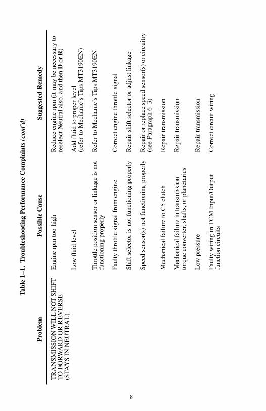
TR
AN
SMIS
SIO
N D
OE
SN
OT
SH
IFT
PR
OPE
RLY
(RO
UG
H S
HIF
TS,
SH
IFT
S O
CC
UR
RIN
G A
T T
OO
LO
WO
R T
OO
HIG
H S
PEE
D)
Eng
ine
idle
spe
ed to
o fa
st (
neut
ral t
o ra
nge
shif
t)A
djus
t eng
ine
idle
spe
ed (
refe
r to
Veh
icle
Se
rvic
e M
anua
l)
Faul
ty th
rottl
e se
nsor
/cir
cuit
Ref
er to
Mec
hani
c’s
Tip
s M
T31
90E
N a
nd/o
r T
roub
lesh
ootin
g M
anua
l TS3
192E
N
Faul
ty o
r st
icki
ng b
leed
bal
l in
C1
posi
tion
hous
ing
Rep
lace
C1
pist
on h
ousi
ng
Exc
essi
ve c
lutc
h ru
nnin
g cl
eara
nce
Reb
uild
tran
smis
sion
and
adj
ust c
lear
ance
s
Inco
rrec
t shi
ft c
alib
ratio
n fo
r ve
hicl
eIn
stal
l cor
rect
cal
ibra
tion
Inst
rum
ent p
anel
tach
omet
er in
corr
ect
Rep
air
or r
epla
ce ta
chom
eter
Inco
rrec
tly c
alib
rate
d el
ectr
onic
sp
eedo
met
erC
alib
rate
ele
ctro
nic
spee
dom
eter
Faul
ty s
peed
sen
sor/
circ
uit
Rep
air
circ
uit o
r re
plac
e sp
eed
sens
or (
refe
r to
Tro
uble
shoo
ting
Man
ual T
S319
2EN
)
Deg
rade
d flu
idC
hang
e tr
ansm
issi
on fl
uid
and
filte
r
Loo
se s
peed
sen
sor
Tig
hten
spe
ed s
enso
r re
tain
ing
brac
ket b
olt
Tabl
e 1–
1.T
roub
lesh
ooti
ng P
erfo
rman
ce C
ompl
aint
s (c
ont’
d)
Pro
blem
Pos
sibl
e C
ause
Sugg
este
d R
emed
y

11
TR
AN
SMIS
SIO
N D
OE
SN
OT
SH
IFT
PR
OPE
RLY
(RO
UG
H S
HIF
TS,
SH
IFT
S O
CC
UR
RIN
G A
T T
OO
LO
WO
R T
OO
HIG
H S
PEE
D)
(con
t’d)
Inco
rrec
t flui
d le
vel
Cor
rect
flui
d le
vel
Shif
t ada
ptiv
es n
ot c
onve
rged
Dri
ve v
ehic
le u
ntil
shif
t ada
ptiv
es a
re
conv
erge
d
Eng
ine
para
met
ers
not c
orre
ctH
ave
OE
M v
erif
y en
gine
par
amet
ers
that
m
ay a
ffec
t tra
nsm
issi
on p
erfo
rman
ce
Low
mai
n pr
essu
reR
epai
r tr
ansm
issi
on
Inte
rmitt
ent p
robl
ems
Che
ck w
irin
g ha
rnes
ses
and
conn
ecto
rs (
see
Tro
uble
shoo
ting
Man
ual T
S319
2EN
)
Loo
se o
r da
mag
ed s
peed
gea
rT
ight
en o
utpu
t flan
ge b
olt o
r re
plac
e sp
eed
gear
Stic
king
val
ves
in c
ontr
ol v
alve
bod
yO
verh
aul c
ontr
ol v
alve
bod
y as
sem
bly
Lea
king
trim
sol
enoi
dsR
epai
r or
rep
lace
trim
sol
enoi
ds (
see
Para
grap
h 6–
9)
Inco
rrec
t cal
ibra
tion
Inst
all c
orre
ct c
alib
ratio
n
Tabl
e 1–
1.T
roub
lesh
ooti
ng P
erfo
rman
ce C
ompl
aint
s (c
ont’
d)
Pro
blem
Pos
sibl
e C
ause
Sugg
este
d R
emed
y

12
AB
NO
RM
AL
AC
TIV
ITIE
S O
R R
ESP
ON
SES
A.
Exc
essi
ve C
reep
in F
irst
and
R
ever
se G
ears
Eng
ine
idle
spe
ed to
o hi
ghA
djus
t to
corr
ect i
dle
spee
d
B.
Veh
icle
Mov
es F
orw
ard
in N
eutr
alC
1 cl
utch
fai
led
or n
ot r
elea
sed
Reb
uild
C1
clut
ch (
refe
r to
tran
smis
sion
Se
rvic
e M
anua
l)
C.
Veh
icle
Mov
es B
ackw
ard
in
Neu
tral
C3
clut
ch f
aile
d or
not
rel
ease
dR
ebui
ld C
3 cl
utch
ass
embl
y (r
efer
to
tran
smis
sion
Ser
vice
Man
ual S
M31
91E
N)
EX
CE
SSIV
E F
LA
RE
—E
NG
INE
OV
ER
SPE
ED
ON
FU
LL
-T
HR
OT
TL
E U
PSH
IFT
S
TPS
Adj
ustm
ent:
—O
vers
trok
e—
Adj
ust T
PS li
nkag
e fo
r pr
oper
str
oke
(ref
er to
Mec
hani
c’s
Tip
s M
T31
90E
N)
—L
oose
—T
ight
en lo
ose
bolts
or
conn
ectio
ns
Inco
rrec
t cal
ibra
tion
Inst
all c
orre
ct c
alib
ratio
n
Inco
rrec
t flui
d le
vel
Add
flui
d to
pro
per
leve
l(r
efer
to M
echa
nic’
s T
ips
MT
3190
EN
)
Stic
king
val
ves
in c
ontr
ol v
alve
bod
y as
sem
bly
Reb
uild
con
trol
val
ve b
ody
asse
mbl
y
Low
mai
n pr
essu
reSe
e L
ow P
ress
ure
sect
ion
Tabl
e 1–
1.T
roub
lesh
ooti
ng P
erfo
rman
ce C
ompl
aint
s (c
ont’
d)
Pro
blem
Pos
sibl
e C
ause
Sugg
este
d R
emed
y

13
EX
CE
SSIV
E F
LA
RE
—E
NG
INE
OV
ER
SPE
ED
ON
FU
LL
-T
HR
OT
TL
E U
PSH
IFT
S (c
ont’
d)
Lea
king
trim
sol
enoi
dsR
epai
r or
rep
lace
trim
sol
enoi
ds (
see
Para
grap
h 6–
9)
Err
atic
spe
ed s
enso
r si
gnal
See
spee
d se
nsor
DT
Cs
Pist
on s
eals
leak
ing
or c
lutc
h pl
ates
sl
ippi
ng in
ran
ge in
volv
edO
verh
aul t
rans
mis
sion
(ref
er to
tran
smis
sion
Se
rvic
e M
anua
l SM
3191
EN
)
RA
NG
E C
LU
TC
H T
RO
UB
LE
SHO
OT
ING
SE
CT
ION
EX
CE
SSIV
E S
LIP
PAG
E A
ND
C
LU
TC
H C
HA
TT
ER
Inco
rrec
t cal
ibra
tion
Inst
all c
orre
ct c
alib
ratio
n
Thr
ottle
pos
ition
sen
sor
out o
f ad
just
men
t or
faile
dA
djus
t or
repl
ace
thro
ttle
posi
tion
sens
or
(ref
er to
Mec
hani
c’s
Tip
s M
T31
90E
N)
Inco
rrec
t spe
ed s
enso
r re
adin
gsSe
e sp
eed
sens
or D
TC
s
Inco
rrec
t flui
d le
vel
Cor
rect
flui
d le
vel
(ref
er to
Mec
hani
c’s
Tip
s M
T31
90E
N)
Mai
n pr
essu
re lo
wR
efer
to tr
ansm
issi
on S
ervi
ce M
anua
l SM
3191
EN
TC
C c
lutc
h no
t app
lied
Insp
ect t
orqu
e co
nver
ter
clut
ch s
yste
m
wir
ing,
pre
ssur
e, a
nd c
ontr
ols;
rep
air
as
nece
ssar
y (r
efer
to tr
ansm
issi
on S
ervi
ce
Man
ual S
M31
91E
N)
Tabl
e 1–
1.T
roub
lesh
ooti
ng P
erfo
rman
ce C
ompl
aint
s (c
ont’
d)
Pro
blem
Pos
sibl
e C
ause
Sugg
este
d R
emed
y

14
A.
Ran
ges
1, 2
, 3, 4
Onl
yC
1 cl
utch
slip
ping
, lea
ks a
t spl
itlin
e ga
sket
, lea
ks a
t rot
atin
g cl
utch
sea
ls,
leak
s at
pis
ton
seal
s, C
1 cl
utch
pla
tes
wor
n
Insp
ect c
ontr
ol m
odul
e ga
sket
, C1
clut
ch
plat
es, a
nd p
isto
n an
d ro
tatin
g se
als;
rep
lace
/re
build
as
nece
ssar
y (r
efer
to tr
ansm
issi
on
Serv
ice
Man
ual S
M31
91E
N)
B.
Ran
ges
4, 5
Onl
yC
2 cl
utch
slip
ping
, lea
ks a
t spl
itlin
e ga
sket
, lea
ks a
t rot
atin
g cl
utch
sea
ls,
leak
s at
pis
ton
seal
s, C
2 cl
utch
pla
tes
wor
n
Insp
ect c
ontr
ol m
odul
e ga
sket
, C2
clut
ch
plat
es, a
nd p
isto
n an
d ro
tatin
g se
als;
rep
lace
/re
build
as
nece
ssar
y (r
efer
to tr
ansm
issi
on
Serv
ice
Man
ual S
M31
91E
N)
C.
Ran
ges
3, 5
, R O
nly
C3
clut
ch s
lippi
ng, l
eaks
at p
isto
n se
als,
C
3 cl
utch
pla
tes
wor
nIn
spec
t C3
clut
ch p
late
s an
d pi
ston
sea
ls;
repl
ace/
rebu
ild a
s ne
cess
ary
(ref
er to
tr
ansm
issi
on S
ervi
ce M
anua
l SM
3191
EN
)
D.
Ran
ge 2
Onl
yC
4 cl
utch
slip
ping
, lea
ks a
t pis
ton
seal
s,
C4
clut
ch p
late
s w
orn
Insp
ect C
4 cl
utch
pla
tes
and
pist
on s
eals
; re
plac
e/re
build
as
nece
ssar
y (r
efer
to
tran
smis
sion
Ser
vice
Man
ual S
M31
91E
N)
E.
Ran
ges
1, R
Onl
yC
5 cl
utch
slip
ping
, lea
ks a
t pis
ton
seal
s,
C5
clut
ch p
late
s w
orn
Insp
ect C
5 cl
utch
pla
tes
and
pist
on s
eals
; re
plac
e/re
build
as
nece
ssar
y (r
efer
to
tran
smis
sion
Ser
vice
Man
ual S
M31
91E
N)
Tabl
e 1–
1.T
roub
lesh
ooti
ng P
erfo
rman
ce C
ompl
aint
s (c
ont’
d)
Pro
blem
Pos
sibl
e C
ause
Sugg
este
d R
emed
y
15
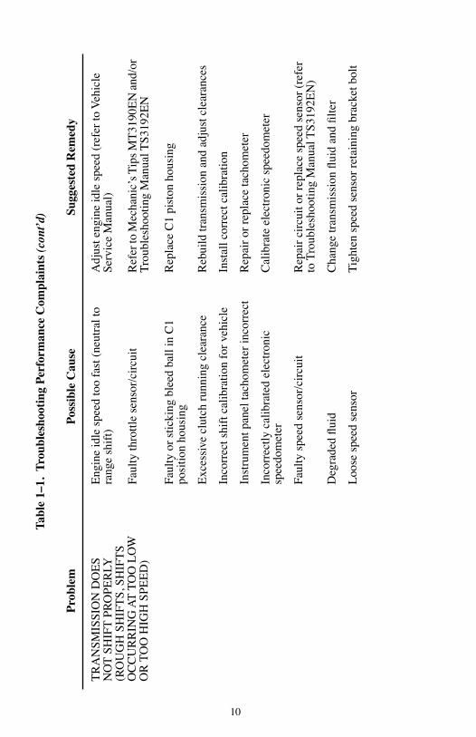
LO
W P
RE
SSU
RE
SE
CT
ION
A.
Low
Mai
n Pr
essu
re in
A
ll R
ange
sIn
corr
ect fl
uid
leve
lC
orre
ct fl
uid
leve
l(r
efer
to M
echa
nic’
s T
ips
MT
3190
EN
)
Plug
ged
or f
aulty
suc
tion
filte
rC
lean
or
repl
ace
oil s
uctio
n fil
ter
elem
ent
(ref
er to
Par
agra
ph 6
–8)
Mai
n pr
essu
re r
egul
ator
val
ve s
ticki
ngO
verh
aul f
ront
sup
port
ass
embl
y (r
efer
to
tran
smis
sion
Ser
vice
Man
ual S
M31
91E
N)
Lea
king
sol
enoi
ds in
con
trol
val
ve b
ody
asse
mbl
yR
epai
r or
rep
lace
sol
enoi
ds (
see
Para
grap
h 6–
9)
Stuc
k or
stic
king
lube
reg
ulat
or v
alve
Ove
rhau
l fro
nt s
uppo
rt a
ssem
bly
(ref
er to
tr
ansm
issi
on S
ervi
ce M
anua
l SM
3191
EN
)
Mai
n pr
essu
re r
egul
ator
val
ve s
prin
g w
eak,
bro
ken,
or
mis
sing
Che
ck s
prin
g an
d re
plac
e if
nec
essa
ry (
refe
r to
tran
smis
sion
Ser
vice
Man
ual
SM31
91E
N)
Con
trol
mod
ule
body
leak
age
(sep
arat
or
plat
e no
t flat
, sep
arat
or p
late
gas
ket
leak
age,
loos
e co
ntro
l val
ve b
ody
bolts
)
Rep
lace
or r
ebui
ld c
ontr
ol m
odul
e as
sem
bly.
C
are
shou
ld b
e ta
ken
whe
n re
mov
ing
and
labe
ling
shif
t spr
ings
(re
fer
to tr
ansm
issi
on
Serv
ice
Man
ual S
M31
91E
N)
Faul
ty o
r in
corr
ect fl
uid
pres
sure
gau
geR
epai
r or
rep
lace
gau
ge
Tabl
e 1–
1.T
roub
lesh
ooti
ng P
erfo
rman
ce C
ompl
aint
s (c
ont’
d)
Pro
blem
Pos
sibl
e C
ause
Sugg
este
d R
emed
y

16
A.
Low
Mai
n Pr
essu
re in
A
ll R
ange
s (c
ont’
d)O
il pu
mp
wor
n or
dam
aged
Rep
lace
or
rebu
ild o
il pu
mp
(ref
er to
tr
ansm
issi
on S
ervi
ce M
anua
l SM
3191
EN
)
Lea
k in
suc
tion
circ
uit
Che
ck s
uctio
n ci
rcui
t for
leak
ing
seal
, ga
sket
, or
mat
ing
surf
ace
B.
Mai
n Pr
essu
re L
ow in
Spe
cific
R
ange
s, N
orm
al P
ress
ure
in O
ther
R
ange
s
Seal
leak
See
SM31
91E
N f
or p
roce
dure
to r
epla
ce
seal
s th
at a
re c
ausi
ng lo
w p
ress
ure
in a
pa
rtic
ular
ran
ge
C.
Low
Lub
rica
tion
Pres
sure
Inco
rrec
t flui
d le
vel
Cor
rect
flui
d le
vel
(ref
er to
Mec
hani
c’s
Tip
s M
T31
90E
N)
Plug
ged
suct
ion
filte
rC
hang
e fil
ter
(ref
er to
Mec
hani
c’s
Tip
s M
T31
90E
N)
Plug
ged
cool
er c
ircu
it fil
ter
Cha
nge
filte
r
Exc
essi
ve in
tern
al fl
uid
leak
age
Che
ck o
ther
pre
ssur
es (
abov
e ite
ms)
; als
o ch
eck
cont
rol m
odul
e m
ount
ing
bolts
; lu
bric
atio
n va
lve
and
spri
ng (
refe
r to
tr
ansm
issi
on S
ervi
ce M
anua
l SM
3191
EN
);
conv
erte
r ho
usin
g to
sep
arat
or p
late
gas
ket
Coo
ler
lines
res
tric
ted
or le
akin
gC
heck
for
kin
ks, l
eaka
ge; r
erou
te o
r re
plac
e lin
es a
s ne
cess
ary
Lub
rica
tion
regu
lato
r va
lve
stic
king
Cle
an o
r re
plac
e re
gula
tor
valv
e
Tabl
e 1–
1.T
roub
lesh
ooti
ng P
erfo
rman
ce C
ompl
aint
s (c
ont’
d)
Pro
blem
Pos
sibl
e C
ause
Sugg
este
d R
emed
y

17
C.
Low
Lub
rica
tion
Pres
sure
(co
nt’d
)C
onve
rter
rel
ief
valv
e st
icki
ngC
lean
or
repl
ace
conv
erte
r re
lief
valv
e
Coo
ler
plug
ged
Cle
an o
r re
plac
e co
oler
Faul
ty g
auge
Rep
air
or r
epla
ce g
auge
AB
NO
RM
AL
STA
LL
SPE
ED
S(S
tall
In F
irst R
ange
— F
ifth
Ran
ge)
A.
Hig
h St
all S
peed
sN
ot in
gea
rSe
lect
D (
Dri
ve)
Low
flui
d le
vel,
aera
ted
fluid
Add
flui
d to
pro
per
leve
l(r
efer
to M
echa
nic’
s T
ips
MT
3190
EN
)
Faul
ty to
rque
con
vert
erR
epla
ce to
rque
con
vert
er
Inco
rrec
t tor
que
conv
erte
rR
epla
ce to
rque
con
vert
er (
refe
r to
tr
ansm
issi
on S
ervi
ce M
anua
l SM
3191
EN
)
Clu
tch
pres
sure
low
Ref
er to
TS3
192E
N E
lect
roni
c T
roub
lesh
ootin
g
C1
or C
5 cl
utch
slip
ping
. N
ote:
Use
the
diag
nost
ic to
ol to
che
ck
turb
ine
spee
d
Reb
uild
C1
or C
5 cl
utch
(re
fer
to
tran
smis
sion
Ser
vice
Man
ual S
M31
91E
N)
Hig
her
pow
er e
ngin
eC
onfir
m p
rope
r en
gine
mat
ch
Tabl
e 1–
1.T
roub
lesh
ooti
ng P
erfo
rman
ce C
ompl
aint
s (c
ont’
d)
Pro
blem
Pos
sibl
e C
ause
Sugg
este
d R
emed
y

18
B.
Low
Sta
ll Sp
eeds
Eng
ine
not p
erfo
rmin
g ef
ficie
ntly
(m
ay
be d
ue to
plu
gged
or
rest
rict
ed in
ject
ors,
hi
gh a
ltitu
de c
ondi
tions
, dir
ty a
ir fi
lters
, ou
t of
time,
thro
ttle
linka
ge, e
lect
roni
c en
gine
con
trol
s pr
oble
m)
Ref
er to
Veh
icle
Eng
ine
Man
ufac
ture
r’s
Man
ual o
r Veh
icle
Ser
vice
Man
ual
Stal
l spe
eds
of 3
3 pe
rcen
t of
norm
al
impl
ies
free
whe
elin
g st
ator
Rep
lace
con
vert
er a
ssem
bly
(ref
er to
tr
ansm
issi
on S
ervi
ce M
anua
l SM
3191
EN
)
Eng
ine
smok
e co
ntro
lsC
ompa
re lu
gbac
k vs
. sta
tic s
tall
spee
d
Inco
rrec
t tor
que
conv
erte
rIn
stal
l cor
rect
torq
ue c
onve
rter
(re
fer
to
tran
smis
sion
Ser
vice
Man
ual S
M31
91E
N)
OV
ER
HE
AT
ING
IN
AL
L R
AN
GE
SA
erat
ed fl
uid
— in
corr
ect fl
uid
leve
lA
djus
t flui
d to
pro
per
leve
l, ch
eck
for
defe
ctiv
e pu
mp
(ref
er to
MT
3190
EN
)
Air
flow
to c
oole
r ob
stru
cted
Rem
ove
air
flow
obs
truc
tion
Eng
ine
over
heat
Cor
rect
ove
rhea
t situ
atio
n (r
efer
to V
ehic
le
Serv
ice
Man
ual)
Inac
cura
te te
mpe
ratu
re g
auge
or
send
ing
unit
Rep
lace
gau
ge a
nd/o
r se
ndin
g un
it
Tabl
e 1–
1.T
roub
lesh
ooti
ng P
erfo
rman
ce C
ompl
aint
s (c
ont’
d)
Pro
blem
Pos
sibl
e C
ause
Sugg
este
d R
emed
y

19
OV
ER
HE
AT
ING
IN
AL
L R
AN
GE
S (c
ont’
d)In
accu
rate
sum
p te
mpe
ratu
re s
enso
rR
epla
ce P
ress
ure
Switc
h M
anif
old
(PSM
) or
inte
rnal
har
ness
(re
fer
to P
arag
raph
s 6–
9)
Inad
equa
te c
oole
r si
zing
See
vehi
cle
OE
M f
or s
peci
ficat
ions
Exc
essi
ve c
oole
r ci
rcui
t pre
ssur
e dr
opC
heck
for
plu
gged
coo
ler,
lines
too
smal
l, co
llaps
ed h
ose,
too
man
y el
bow
s in
cir
cuit
Tra
nsm
issi
on c
oole
r lin
es r
ever
sed
Con
nect
coo
ler
lines
pro
perl
y (o
il an
d w
ater
sh
ould
flow
in o
ppos
ite d
irec
tions
)
Flui
d co
oler
line
s re
stri
cted
Rem
ove
rest
rict
ions
, cle
an o
r re
plac
e lin
es
(ref
er to
Veh
icle
Ser
vice
Man
ual)
Torq
ue c
onve
rter
(w
rong
con
vert
er, n
o to
rque
con
vert
er c
lutc
h, s
tuck
sta
tor,
or
slip
ping
sta
tor)
Rep
lace
or
repa
ir c
onve
rter
ass
embl
y (r
efer
to
tran
smis
sion
Ser
vice
Man
ual
SM31
91E
N)
Not
e: S
tuck
sta
tor
will
not
allo
w c
ool d
own
in n
eutr
al
Coo
ler
flow
loss
due
to in
tern
al
tran
smis
sion
leak
age
Ove
rhau
l tra
nsm
issi
on (r
efer
to tr
ansm
issi
on
Serv
ice
Man
ual S
M31
91E
N)
Tabl
e 1–
1.T
roub
lesh
ooti
ng P
erfo
rman
ce C
ompl
aint
s (c
ont’
d)
Pro
blem
Pos
sibl
e C
ause
Sugg
este
d R
emed
y

20
FLU
ID C
OM
ES
OU
T O
F T
HE
FL
UID
FIL
L T
UB
E A
ND
/OR
B
RE
AT
HE
R
Dip
stic
k lo
ose
Tig
hten
cap
, rep
lace
if n
eces
sary
Flui
d le
vel t
oo h
igh
Dra
in to
pro
per
leve
l(r
efer
to M
echa
nic’
s T
ips
MT
3190
EN
)
Flui
d le
vel t
oo lo
wA
dd fl
uid
to p
rope
r le
vel
Bre
athe
r st
oppe
d up
— c
logg
edC
lean
or
repl
ace
brea
ther
(re
fer
to
tran
smis
sion
Ser
vice
Man
ual S
M31
91E
N)
Flui
d co
ntam
inat
ed w
ith f
orei
gn li
quid
Dra
in a
nd r
epla
ce fl
uid.
Loc
ate
and
fix
sour
ce o
f ad
ditio
nal fl
uid
(ref
er to
Mec
hani
c’s
Tip
s M
T31
90E
N).
Dip
stic
k or
fill
tube
sea
l wor
nR
epla
ce s
eals
or
dips
tick
Inco
rrec
t dip
stic
k m
arki
ngC
alib
rate
dip
stic
k(r
efer
to M
echa
nic’
s T
ips
MT
3190
EN
)
NO
ISE
OC
CU
RR
ING
IN
TE
RM
ITT
EN
TLY
(B
UZ
ZIN
G)
Low
flui
d le
vel
Add
flui
d to
pro
per
leve
l(r
efer
to M
echa
nic’
s T
ips
MT
3190
EN
)
Air
leak
in o
il su
ctio
n sc
reen
can
iste
rR
epla
ce o
il su
ctio
n sc
reen
can
iste
r (r
efer
to
tran
smis
sion
Ser
vice
Man
ual S
M31
91E
N)
Clo
gged
suc
tion
filte
rR
epla
ce fi
lter
(ref
er to
Par
agra
ph 6
–8)
Tabl
e 1–
1.T
roub
lesh
ooti
ng P
erfo
rman
ce C
ompl
aint
s (c
ont’
d)
Pro
blem
Pos
sibl
e C
ause
Sugg
este
d R
emed
y

21
NO
ISE
OC
CU
RR
ING
IN
TE
RM
ITT
EN
TLY
(B
UZ
ZIN
G)
(con
t’d)
Aer
ated
flui
d ca
uses
noi
sy p
ump
Cor
rect
flui
d le
vel
(ref
er to
Mec
hani
c’s
Tip
s M
T31
90E
N)
Low
mai
n pr
essu
re c
ause
s m
ain
regu
lato
r va
lve
to o
scill
ate
See
Serv
ice
Man
ual S
M31
91E
N
LE
AK
ING
FL
UID
(TR
AN
SMIS
SON
OU
TPU
T)
Faul
ty o
r m
issi
ng s
eal a
t out
put fl
ange
Inst
all n
ew li
p-ty
pe s
eal i
n re
ar o
f tr
ansm
issi
on h
ousi
ng (
refe
r to
tran
smis
sion
Se
rvic
e M
anua
l SM
3191
EN
)(s
ee P
arag
raph
6–6
)
Mac
hine
lead
on
outp
ut fl
ange
sea
l su
rfac
eR
epla
ce fl
ange
Rea
r co
ver
poro
sity
Rep
air
or r
epla
ce c
over
Flan
ge w
orn
at s
eal s
urfa
ceR
epla
ce fl
ange
Insu
ffici
ent s
eala
nt a
roun
d se
al O
DW
hen
repl
acin
g se
al, r
efer
to P
arag
raph
6–6
Dam
aged
or
mis
sing
out
put b
olt w
ashe
r se
alR
epla
ce o
utpu
t bol
t sea
ling
was
her
Dam
aged
, mis
sing
, or l
oose
out
put fl
ange
bo
ltR
epla
ce a
nd/o
r to
rque
out
put fl
ange
bol
ts
(see
Par
agra
ph 6
–1)
Tabl
e 1–
1.T
roub
lesh
ooti
ng P
erfo
rman
ce C
ompl
aint
s (c
ont’
d)
Pro
blem
Pos
sibl
e C
ause
Sugg
este
d R
emed
y

22
TR
AN
SMIS
SIO
N I
NPU
TFr
ont s
eal l
eaks
Man
ifol
d ga
sket
leak
s
Rep
lace
fro
nt s
eal (
refe
r to
Par
agra
ph 6
–10)
Rep
lace
man
ifol
d ga
sket
(ref
er to
Par
agra
ph 6
–5)
Fron
t sup
port
bol
t sea
ls le
akin
gR
epla
ce b
olt s
eals
Con
vert
er le
aks
Che
ck c
onve
rter
sea
ls, c
rack
ed c
onve
rter
pu
mp
tang
s, c
onve
rter
cov
er, o
r co
nver
ter
hous
ing
poro
sity
; rep
lace
par
ts a
s re
quir
ed
(ref
er to
tran
smis
sion
Ser
vice
Man
ual
SM31
91E
N)
Spin
-on
filte
r le
akin
gR
epla
ce fi
lter
Mai
n pr
essu
re p
lug
leak
Rep
lace
or
torq
ue m
ain
pres
sure
plu
g
Pum
p bu
shin
g sh
ows
exce
ssiv
e w
ear
Reb
uild
and
rep
air
pum
p
Tabl
e 1–
1.T
roub
lesh
ooti
ng P
erfo
rman
ce C
ompl
aint
s (c
ont’
d)
Pro
blem
Pos
sibl
e C
ause
Sugg
este
d R
emed
y
23
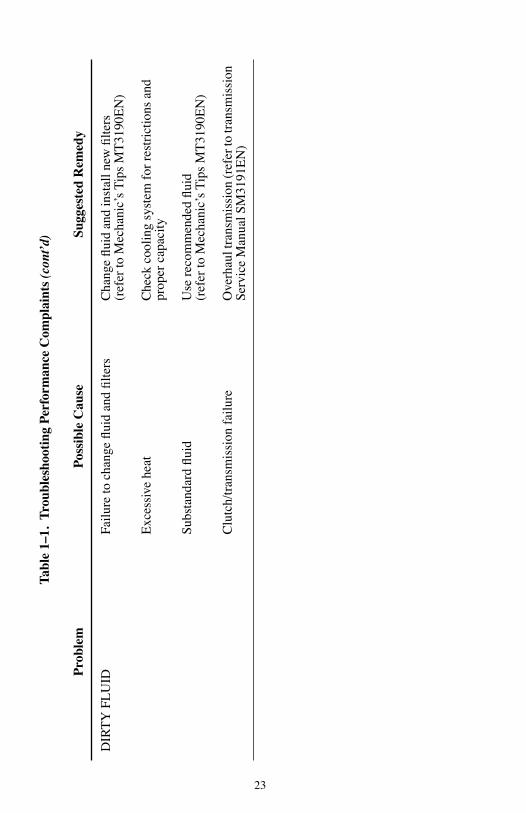
DIR
TY
FL
UID
Failu
re to
cha
nge
fluid
and
filte
rsC
hang
e flu
id a
nd in
stal
l new
filte
rs(r
efer
to M
echa
nic’
s T
ips
MT
3190
EN
)
Exc
essi
ve h
eat
Che
ck c
oolin
g sy
stem
for
res
tric
tions
and
pr
oper
cap
acity
Subs
tand
ard
fluid
Use
rec
omm
ende
d flu
id(r
efer
to M
echa
nic’
s T
ips
MT
3190
EN
)
Clu
tch/
tran
smis
sion
fai
lure
Ove
rhau
l tra
nsm
issi
on (r
efer
to tr
ansm
issi
on
Serv
ice
Man
ual S
M31
91E
N)
Tabl
e 1–
1.T
roub
lesh
ooti
ng P
erfo
rman
ce C
ompl
aint
s (c
ont’
d)
Pro
blem
Pos
sibl
e C
ause
Sugg
este
d R
emed
y

24
1–3. TRANSMISSION STALL TEST AND NEUTRAL COOL-DOWN CHECK
a. Purpose. When a vehicle is performing unsatisfactorily, use the stall test to determine if the malfunction is in the engine or in the transmission. The neutral cool-down check uses a two minute cooling period after the stall to gather fluid temperature data for troubleshooting.
• The engine stall rpm under load is compared to the engine manufacturer’s specified rpm for the stall test.
• Connect a tachometer (the Diagnostic Tool can read engine rpm) of known accuracy to the engine and install a temperature probe into the converter-out (to cooler) hose. Bring the transmission to the normal operating temperature range of 71˚C–93˚C (160˚F–200˚F).
NOTE: The stall test should only be performed by a qualified service technician.
NOTE: The engine manufacturer’s test data must be available for the stall test. This data can be obtained from the engine manufacturer or from the equipment dealer or distributor or from SCAAN.
NOTE: The Diagnostic Tool can read sump temperature to show when normal operating temperatures have been reached and the temperature has stabilized.
WARNING: To help avoid injury or property damage caused by sudden and unexpected vehicle movement, do not start a stationary stall test until you:
• Put the transmission in P (Park) or N (Neutral)…and
• Apply the parking brake and service brake…and
• Chock the vehicle wheels and take any other steps necessary to keep the vehicle from moving…and
• Warn personnel to keep clear of the vehicle and its path.
CAUTION: DO NOT conduct a stall test in R (Reverse) range. The torque produced in reverse range can damage the vehicle driveline or axle.
25
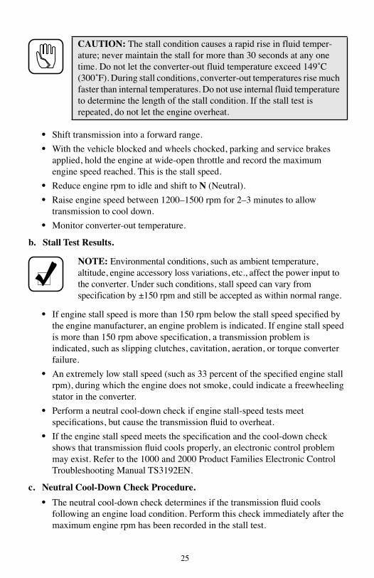
• Shift transmission into a forward range.
• With the vehicle blocked and wheels chocked, parking and service brakes applied, hold the engine at wide-open throttle and record the maximum engine speed reached. This is the stall speed.
• Reduce engine rpm to idle and shift to N (Neutral).
• Raise engine speed between 1200–1500 rpm for 2–3 minutes to allow transmission to cool down.
• Monitor converter-out temperature.
b. Stall Test Results.
• If engine stall speed is more than 150 rpm below the stall speed specified by the engine manufacturer, an engine problem is indicated. If engine stall speed is more than 150 rpm above specification, a transmission problem is indicated, such as slipping clutches, cavitation, aeration, or torque converter failure.
• An extremely low stall speed (such as 33 percent of the specified engine stall rpm), during which the engine does not smoke, could indicate a freewheeling stator in the converter.
• Perform a neutral cool-down check if engine stall-speed tests meet specifications, but cause the transmission fluid to overheat.
• If the engine stall speed meets the specification and the cool-down check shows that transmission fluid cools properly, an electronic control problem may exist. Refer to the 1000 and 2000 Product Families Electronic Control Troubleshooting Manual TS3192EN.
c. Neutral Cool-Down Check Procedure.
• The neutral cool-down check determines if the transmission fluid cools following an engine load condition. Perform this check immediately after the maximum engine rpm has been recorded in the stall test.
CAUTION: The stall condition causes a rapid rise in fluid temper-ature; never maintain the stall for more than 30 seconds at any one time. Do not let the converter-out fluid temperature exceed 149˚C (300˚F). During stall conditions, converter-out temperatures rise much faster than internal temperatures. Do not use internal fluid temperature to determine the length of the stall condition. If the stall test is repeated, do not let the engine overheat.
NOTE: Environmental conditions, such as ambient temperature, altitude, engine accessory loss variations, etc., affect the power input to the converter. Under such conditions, stall speed can vary from specification by ±150 rpm and still be accepted as within normal range.
26
• Record the converter-out fluid temperature.
• Reduce the engine rpm to idle and shift to N (Neutral). Run the engine at 1200–1500 rpm for two minutes to cool the fluid.
• At the end of two minutes, record the converter-out fluid temperature. Converter-out fluid temperature should return to within the normal operating temperature range.
• If the fluid does not cool during the two minute cool-down check, a stuck stator may be the source of the problem.
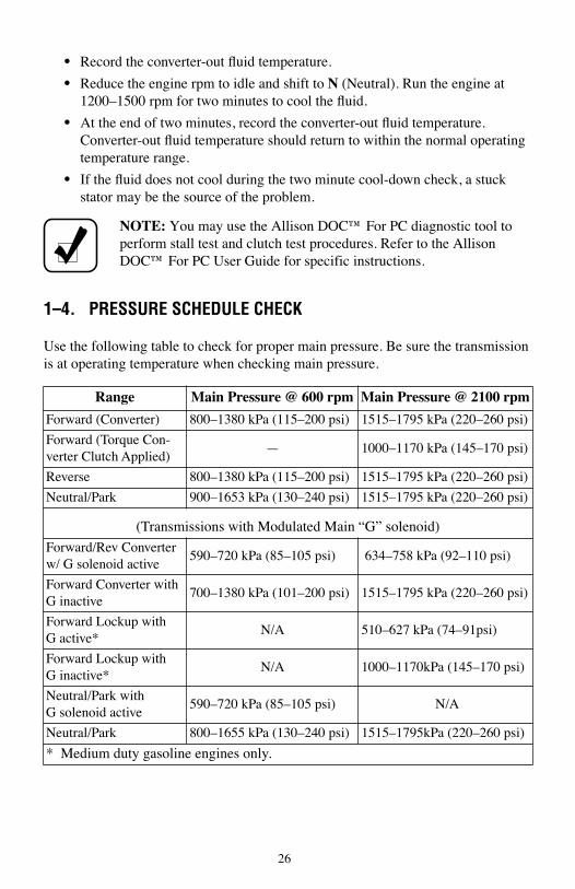
1–4. PRESSURE SCHEDULE CHECK
Use the following table to check for proper main pressure. Be sure the transmission is at operating temperature when checking main pressure.
NOTE: You may use the Allison DOC™ For PC diagnostic tool to perform stall test and clutch test procedures. Refer to the Allison DOC™ For PC User Guide for specific instructions.
Range Main Pressure @ 600 rpm Main Pressure @ 2100 rpm
Forward (Converter) 800–1380 kPa (115–200 psi) 1515–1795 kPa (220–260 psi)
Forward (Torque Con-verter Clutch Applied)
— 1000–1170 kPa (145–170 psi)
Reverse 800–1380 kPa (115–200 psi) 1515–1795 kPa (220–260 psi)
Neutral/Park 900–1653 kPa (130–240 psi) 1515–1795 kPa (220–260 psi)
(Transmissions with Modulated Main “G” solenoid)
Forward/Rev Converter w/ G solenoid active
590–720 kPa (85–105 psi) 634–758 kPa (92–110 psi)
Forward Converter with G inactive
700–1380 kPa (101–200 psi) 1515–1795 kPa (220–260 psi)
Forward Lockup with G active*
N/A 510–627 kPa (74–91psi)
Forward Lockup with G inactive*
N/A 1000–1170kPa (145–170 psi)
Neutral/Park withG solenoid active
590–720 kPa (85–105 psi) N/A
Neutral/Park 800–1655 kPa (130–240 psi) 1515–1795kPa (220–260 psi)
* Medium duty gasoline engines only.
27
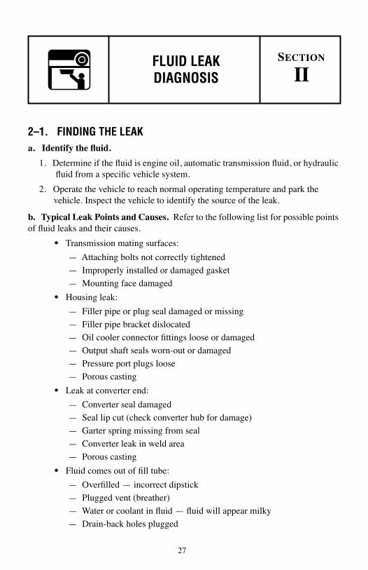
2–1. FINDING THE LEAKa. Identify the fluid.
1. Determine if the fluid is engine oil, automatic transmission fluid, or hydraulic fluid from a specific vehicle system.
2. Operate the vehicle to reach normal operating temperature and park the vehicle. Inspect the vehicle to identify the source of the leak.
b. Typical Leak Points and Causes. Refer to the following list for possible points of fluid leaks and their causes.
• Transmission mating surfaces:
— Attaching bolts not correctly tightened
— Improperly installed or damaged gasket
— Mounting face damaged
• Housing leak:
— Filler pipe or plug seal damaged or missing
— Filler pipe bracket dislocated
— Oil cooler connector fittings loose or damaged
— Output shaft seals worn-out or damaged
— Pressure port plugs loose
— Porous casting
• Leak at converter end:
— Converter seal damaged
— Seal lip cut (check converter hub for damage)
— Garter spring missing from seal
— Converter leak in weld area
— Porous casting
• Fluid comes out of fill tube:
— Overfilled — incorrect dipstick
— Plugged vent (breather)
— Water or coolant in fluid — fluid will appear milky
— Drain-back holes plugged
FLUID LEAK DIAGNOSIS
SECTION
II

28
1. Visually inspect the suspected area. Inspect all the gasket mating surfaces for leaks.
2. If the leak still cannot be identified, then clean the suspected area with a degreaser, steam, or spray solvent. Clean and dry the area. Operate the vehicle for several miles at varying speeds. Inspect the vehicle for leaks. If the source of the leak is still not identified, use the powder method, and/or black light and dye method as explained below.
c. Powder Method.
• Clean the suspected area.
• Apply an aerosol-type white powder.
• Operate the vehicle under normal operating conditions.
• Visually inspect the suspected area and trace the leak path over the white powder surface to the source.
d. Black Light and Dye Method.
• Pour the specified amount of dye into the transmission fill tube.
• Operate the vehicle in normal operating conditions.
• Direct the black light toward the suspected area. The dyed fluid will appear as a brightly colored path leading to the source.
e. Repairing the Leak. Once the leak has been traced back to its source, inspect the leaking part for the following conditions, and repair the leaking part.
• Gaskets:
— Fluid level/pressure is too high
— Plugged vent or drain-back holes
— Improperly tightened fasteners or dirty/damaged threads
— Warped flanges or sealing surfaces
— Scratches, burrs, or other damage to a sealing surface
— Damaged or worn-out gasket
CAUTION: When cleaning the transmission, do not spray steam, water, or cleaning solution directly at the breather (oil vent). Spraying steam, water, or cleaning solution at the breather can force the water or cleaning solution into the transmission and contaminate the transmission fluid.
NOTE: Dye and black light kits are available for finding leaks. Refer to the manufacturer’s directions when using the kits. See kit directions for the color of the fluid dye mix.
29
— Cracked or porous casting adjacent to the gasket
— Improper sealant used (where applicable)
• Seals:
— Fluid level/pressure is too high
— Plugged vent or drain-back holes
— Damaged seal bore
— Damaged or worn-out seal
— Improper installation
— Cracks in component
— Output yoke bearing surface scratched, nicked, or damaged
— Loose or worn-out bearing causing excess seal wear
• Sealing Flange:
— Inspect the sealing flange for bends; replace the part with the damaged flange.

30
3–1. SHIFT SELECTOR AND CABLE/LINKAGEa. Adjustment. The transmission internal detent lever and spring must dictate the position of the manual selector valve in the control valve body. Any customer-furnished shift selector system must be designed and adjusted to accomplish this positioning. The shift selector must move the internal detent lever from position to position and not interfere with the ability of the internal detent spring to position the manual selector valve. When the internal detent spring is in the center of a detent lever position, the shift selector handle should be in the center of the shift selector gate (see Figure 3–1). Check the shift selector adjustment as follows:
1. Center the shift selector lever at the center of a mid-position gate such as OD (Overdrive).
2. Disconnect the selector linkage/cable at the transmission shift lever.
Figure 3–1. Proper Shift Selector Adjustment
CAUTION: Internal transmission damage will occur if the following instructions are not followed:
• DO NOT drive the selector lever onto the selector shaft
• DO NOT use an impact wrench to tighten the shift lever retaining nut. Hold the lever with a wrench while tightening the nut (see Figure 3–4).
R
N
D
3
2
1
“Gates” in shiftselector permittransmission
detent to determineactual selector
shaft orientation
V05806
SHIFT SELECTOR AND CABLE/LINKAGE
SECTION
III
31
3. Be sure that the transmission shift lever is seated against the shoulder on the selector shaft and the retaining nut is tightened (proper tightening torque is 20–27 N·m (15–20 lb ft)).
4. Rotate the transmission selector lever to its extreme clockwise position (see Figure 3–2; this is P (Park) for the 1000 and 2200 models and the 2400 Series™ and PB (Park Brake Apply) for the 2100 and 2500 models and the 2000 Series™).
5. Manually rotate the lever in the counter-clockwise direction to the same position as the shift lever at the operators console (three detents to reach OD in our example from Step 1).
6. Reinstall the clevis pin in the shift selector linkage/cable. The clevis pin should freely slide into the transmission shift lever and not bind or move the lever. This is known as “free pin” fit. Adjust the clevis as required to achieve “free pin” fit.
7. Check for “free pin” fit in the selector positions at the extreme ends of the shift selector travel (1 and P for 1000 and 2200 models and the 2400 Series™ units or 1 and either PB or R for the 2100 and 2500 models and the 2000 Series™ units).
WARNING: Although the PB (Park Brake Apply) position is available at the transmission for 2100 and 2500 models and the 2000 Series™ transmission, the customer-supplied shift selector at the operator’s console will only have a PB (Park Brake Apply) position when the vehicle is equipped with a park brake apply system. For 2100 and 2500 models and the 2000 Series™ equipped vehicles WITHOUT a park brake apply system, there must not be a PB (Park Brake Apply) position on the selector at the operator’s console.

32
Figure 3–2. Transmission Shift Lever Positions
R N ODPD
21
45.5¡56.2¡ 67.0¡
SELECTOR SHAFT FLATSAS SHOWN INDICATE PARK POSITION
1000 and 2200 TRANSMISSIONS
77.8¡
34.3¡
23.2¡
20.9¡
PARK PAWLAPPLY
R N ODPBD
21
45.5¡56.2¡ 67.0¡
SELECTOR SHAFT FLATSAS SHOWN INDICATE PARK-BRAKE APPLY POSITION
2100 and 2500 TRANSMISSION
77.8¡
34.3¡
23.2¡
20.9¡
Only used on vehicleswith automatic park-brake
apply system (no parkpawl on 2000 Series™ –
Transmission is in neutral)
R – REVERSEN – NEUTRALOD – OVERDRIVE (Ranges 1 – 5, where 5th is overdrive)D – DRIVE (Ranges 1 – 4)
NUT – 29520052M10 x 1.5 metric nut
Torque to 20–27 N•m(not supplied with transmission)
Hold the selector lever toavoid internal damage
while tightening the nut
Do not use power impactwrench to torque
Selector shaftlever againstshoulder on shaft
VERTICALTRANSMISSIONCENTERLINE
V05807.00.01

33
b. Replacement. Replace the shift selector, linkage or cable whenever it does not shift the transmission to the range indicated at the shift selector or when it cannot be adjusted to achieve “free pin” fit as described in the procedure above. Use the following procedure for replacing the shift selector, linkage or cable.
1. Use process of elimination to find the problem source.
2. Disconnect the shift linkage/cable at the transmission shift lever end. Move the transmission shift lever through each detent position. If function is normal, the problem must be in the linkage/cable or in the shift selector itself. If detents cannot be felt or if excessive force is needed to move the lever, then the problem may be inside the transmission. Proceed to appropriate repair procedure.
3. Disconnect the linkage/cable from the shift selector at the operator’s console. If shift selector operation is normal, replace the linkage/cable. If operation is not normal, replace the shift selector.
4. Reconnect all components, properly adjust, and be sure that normal function has been restored.
3–2. NEUTRAL START/BACKUP (NSBU) SWITCH
a. Adjustment. Use the following procedure when diagnostic trouble codes have been logged and the corrective action is to adjust the NSBU switch or transmission ranges are inhibited.
1. Disconnect the shift linkage/cable from the shift lever at the transmission.
2. With a wrench keeping the shift lever from rotating (see Figure 3–4), remove the nut from the end of the selector shaft. Carefully remove the selector lever from the selector shaft.
3. Remove the dust shield from a single connector NSBU switch.
4. Loosen the two bolts which attach the NSBU switch to the main housing so that the NSBU switch and bracket may be rotated with some effort.
5. Make sure the selector shaft is in the N (Neutral) position (using a wrench on the selector shaft flats, rotate the shaft to its furthest clockwise position and then rotate counter-clockwise two detents — see Figure 3–2).
6. For a one-connector NSBU switch, position special tool J 41364-A (see Figure 3–3 over the selector shaft so two tabs on the tool engage two slots in the NSBU switch just outside the selector shaft. Rotate the NSBU switch and bracket until the single tab at the other end of the tool engages the single slot at the top-front of the NSBU switch.
7. For a two-connector NSBU switch, position special tool J 41364-A (see Figure 3–3) over the selector shaft so two tabs on the tool engage two slots in the NSBU switch just outside the selector shaft. Rotate the NSBU switch and bracket until the single tab at the end of the tool engages the slot at the top-rear of the NSBU switch.

34
Figure 3–3. Adjusting NSBU Switch Using Special Tool
8. While holding the special tool in engagement with the NSBU switch, install the bolt closest to the engine and tighten it enough to keep the NSBU switch from rotating, then install the rear bolt. Tighten both bolts to 24–29 N·m (18–21 lb ft).
9. Install the dust shield over the selector shaft and the dust shield alignment pin.
10. Install the dust shield retaining clip onto the dust shield alignment pin.
11. Reinstall the shift lever. With a wrench keeping the shift lever from rotating, install the nut on the end of the selector shaft and tighten the nut to 20–27 N·m (15–20 lb ft). Reconnect the shift selector linkage/cable to the shift lever. Check for “free pin” fit (refer to Paragraph 3–1).
12. Connect the wiring harness to the NSBU switch.
13. Drive the vehicle and see if diagnostic codes reappear or if the problem has been resolved by adjustment. If the problem has not been resolved, replace the NSBU switch.
CAUTION: Internal transmission damage will occur if the following instructions are not followed:
• DO NOT drive the selector lever onto the selector shaft
• DO NOT use an impact wrench to tighten the shift lever retaining nut. Hold the lever with a wrench while tightening the nut (see Figure 3–4).
CURRENTNSBU SWITCH
FORMERNSBU SWITCH
NSBU SWITCH ADJUSTING TOOL
J-41364-A
TOOLALIGNS
WITHCORRESPONDING
GUIDES
TOOLALIGNS WITH
CORRESPONDINGGUIDES
SPLASHSHIELD
RETAINER
V08088.02.00

35
b. Replacement. Replace the NSBU switch when diagnostic codes still occur and after the NSBU switch has been readjusted. Use the following procedure to replace the NSBU switch.
1. Disconnect the wiring harness from the NSBU switch. Disconnect the shift linkage/cable from the shift lever at the transmission.
2. With a wrench (1) keeping the shift lever (4) from rotating (see Figure 3–4), remove the nut (3) from the end of the selector shaft. Carefully remove the selector lever (2) from the selector shaft.
3. Inspect the selector shaft for a wear created shoulder or burr. Remove any shoulder or burr with a file.
4. Remove the two bolts (6) which attach the NSBU switch to the main housing. Remove the NSBU switch by sliding it outward over the selector shaft.
5. Make sure the selector shaft is in the N (Neutral) position (using a wrench on the selector shaft flats, rotate the shaft to its furthest clockwise position and then rotate counter-clockwise two detents—see Figure 3–2).
6. For a one-connector NSBU switch, slide the new NSBU switch (5) over the selector shaft maintaining the correct NSBU switch to selector shaft alignment (see Figure 3–3). Install the two bolts which attach the NSBU switch to the main housing. Dust shield (1) (refer to Figure 3–5) is retained to the NSBU switch.
Figure 3–4. Restraining the Selector Lever
V08086.01.00
346 5
21
6
®

36
Figure 3–5. Installing New NSBU Switch
7. For a two-connector NSBU switch, position special tool J 41364-A (see figure 3-3) over the selector shaft so two tabs on the tool engage two slots in the NSBU switch just outside the selector shaft. Rotate the NSBU switch and bracket until the single tab at the end of the tool engages the slot at the top-rear of the NSBU switch.
8. Install the NSBU retaining bolt closest to the engine and tighten it enough to keep the NSBU switch from rotating, then install the rear bolt. Tighten both bolts to 24–29 N·m (18–21 lb ft).
9. Reinstall the shift lever. With a wrench keeping the shift lever from rotating, install the nut on the end of the selector shaft and tighten the nut to 20–27 N·m (15–20 lb ft). Reconnect the shift selector linkage/cable to the shift lever.
10. Connect the wiring harness connector to the NSBU switch.
CAUTION: Internal transmission damage will occur if the following instructions are not followed:
• DO NOT drive the selector lever onto the selector shaft
• DO NOT use an impact wrench to tighten the shift lever retaining nut. Hold the lever with a wrench while tightening the nut (see Figure 3–4).
V07184.02.00
1
3
2

37
4–1. REMOVAL
Use the following procedure whenever the selector shaft seal must be removed with the selector shaft in place.
1. Disconnect the wiring harness from the NSBU switch. Disconnect the shift linkage/cable from the shift lever at the transmission.
2. With a wrench keeping the shift lever from rotating, remove the nut from the end of the selector shaft. Carefully remove the selector lever from the selector shaft.
3. Inspect the selector shaft for a shoulder or burr. Remove any shoulder or burr with a file.
4. Remove the two bolts which attach the NSBU switch to the main housing. Remove the NSBU switch by sliding it outward over the selector shaft.
5. Slide special tool J 43911 over the selector shaft with the threaded end towards the seal. Be sure that the jackscrew is backed off and will not interfere with installation of the removal tool (see Figure 4–1). Rotate the removal tool so that the threads on the end of the tool engage the steel shell of the seal. Use a wrench to be sure that the removal tool is firmly attached to the seal.
6. Apply a wrench to the jackscrew and rotate it in the clockwise direction to remove the seal from the bore. Discard the old seal.
4–2. INSTALLATION
Use the following procedure to install the selector shaft seal with the selector shaft in place.
1. If not done previously, inspect the selector shaft for a shoulder or burr. Re-move any shoulder or burr with a file.
2. Carefully slide a new selector shaft seal over the selector shaft with the wide face of the steel case facing outward (see Figure 4–2). Position the seal so that it is starting to enter the seal bore.
SELECTORSHAFT SEAL
REPLACEMENT
SECTION
IV

38
Figure 4–1. Selector Shaft Seal Removal
Figure 4–2. Selector Shaft Seal Installation
SELECTOR SHAFT
J 43911 Threaded end toward seal
V05800
SELECTOR SHAFT SEAL
V05801
NEW SEAL – Started into seal bore
SELECTOR SHAFT
J 43909
39
3. Obtain special tool J 43909 and remove the inner sleeve so that the tool will slide over the selector shaft.
4. Slide the special tool into position so that the end of the tool contacts the seal being installed (see Figure 4–2). Use a mallet to strike the special tool and drive the new seal into the seal bore until it is seated at the bottom of the bore.
5. Make sure the selector shaft is in the N (Neutral) position (using a wrench on the selector shaft flats, rotate the shaft to its furthest clockwise position and then rotate counter-clockwise two detents—see Figure 3–2).
6. Slide the NSBU switch over the selector shaft. Install the two bolts which attach the NSBU switch to the main housing so that the NSBU switch and bracket may be rotated with some effort.
7. Position special tool J 41364-A (see Figure 3–3) over the selector shaft so two tabs on the tool engage two slots in the NSBU switch just outside the selector shaft. Rotate the NSBU switch and bracket until the single tab at the other end of the tool engages the single slot at the top of the NSBU switch.
8. While holding the special tool in engagement with the NSBU switch, tighten the two bolts which attach the NSBU switch to the main housing to 24–29 N·m (18–21 lb ft).
9. Reinstall the shift lever. With a wrench keeping the shift lever from rotating, install the nut on the end of the selector shaft and tighten the nut to 20–27 N·m (15–20 lb ft). Reconnect the shift selector linkage/cable to the shift lever.
CAUTION: Internal transmission damage will occur if the following instructions are not followed:
• DO NOT drive the selector lever onto the selector shaft
• DO NOT use an impact wrench to tighten the shift lever retaining nut. Hold the lever with a wrench while tightening the nut (see Figure 3–4).

40
5–1. ADJUSTMENT
Parking brakes are customer-supplied. Follow the vehicle manufacturers or brake manufacturers instructions for adjustment. Use the following general procedure if specific information is not readily available.
1. Chock wheels to prevent vehicle movement.
2. Be sure that the parking brake apply handle or pedal is in the OFF position.
3. Disconnect the brake apply linkage/cable from the parking brake apply lever at the transmission.
4. Pull on the parking brake apply lever to remove any slack between the apply lever and the brake shoes. Hold the lever in this position and see if the apply linkage/cable connection aligns with the hole in the apply lever. Adjust the clevis or other adjustment device as required to provide proper alignment.
5. Reconnect the brake apply linkage/cable to the parking brake apply lever.
6. Do a trial parking brake apply to check that the adjustment was successful and the parking brake can be completely applied.
5–2. REPLACEMENT
Use vehicle manufacturers or brake manufacturers instructions whenever possible. Use the following general procedure whenever the parking brake must be replaced and no other instructions are available.
WARNING: Chock wheels to prevent vehicle from moving when parking brake is being adjusted or replaced.
WARNING: Chock wheels to prevent vehicle from moving when parking brake is being adjusted or replaced.
PARKINGBRAKE
SECTION
V

41
1. Chock wheels to prevent vehicle movement.
2. Disconnect the parking brake apply linkage/cable from the parking brake apply lever.
3. Disconnect the vehicle driveline from the transmission output flange/yoke. Secure the driveline so that it does not interfere with the removal of parking brake components.
4. Remove the nuts or bolts that attach the parking brake drum to the output flange/yoke. Remove the brake drum.
5. Remove the bolt and sealing washer that attaches the output flange/yoke to the transmission output shaft. Remove the output flange/yoke.
6. Remove the four bolts that attach the parking brake assembly to the rear cover of the transmission. Remove the parking brake assembly.
7. Install the new parking brake assembly in the same position as the one that was removed. Install four bolts which attach the brake assembly to the main housing. Tighten the bolts to 90–110 N·m (66–81 lb ft).
8. Lubricate the internal splines and the rear seal journal of the output flange/yoke with clean transmission fluid. Install the output flange/yoke on the transmission output shaft.
9. Install the bolt and sealing washer that retains the output flange/yoke to the transmission output shaft. Tighten the bolt to 110–135 N·m (80–100 lb ft).
10. Install the parking brake drum over the shoes on the parking brake assembly. Install the nuts/bolts that attach the parking brake drum to the output flange/yoke. Tighten the bolts to specification.
11. Connect the vehicle driveline to the output flange/yoke.
12. Adjust the parking brake linkage/cable (refer to Paragraph 5–1).
CAUTION: Apply the parking brake gradually over 10–15 seconds during burnishing. Dynamic braking is not an accepted practice for normal operation. Abrupt dynamic apply may cause transmission damage.
42
5–3. BURNISHING
After installing a new parking brake assembly, be sure to follow the burnishing procedure to attain full holding capacity. Follow the brake manufacturers recommended burnishing procedure. If a manufacturers procedure is not available, use the following procedure which is based on paragraph 7.3.2 of SAE procedure J360. Make ten stops from a maximum speed of 15 kph (9.5 mph) using only the parking brake to retard the vehicle. Space the stops at least 4 km (2.5 miles) apart and operate the vehicle at a minimum speed of 30 kph (18.5 mph) between each stop. Be sure to readjust the parking brake linkage when the burnishing procedure is completed.
CAUTION: Avoid sustained use of the parking brake while the engine is running and the transmission is in any selector position other than N (Neutral), P (Park), or PB (Park Brake Apply). Failure to observe this practice may cause transmission overheating and premature failure.

43
6–1. OUTPUT FLANGE/YOKE REPLACEMENT
Use the following procedure whenever an output flange/yoke requires replacement due to damage or wear.
1. Chock wheels to prevent vehicle movement.
2. If present, disconnect the parking brake apply linkage/cable from the parking brake apply lever.
3. Disconnect the vehicle driveline from the transmission output flange/yoke. Secure the driveline so that it does not interfere with the removal of parking brake components or the output flange/yoke.
4. If present, remove the nuts or bolts that attach the parking brake drum to the output flange/yoke. Remove the brake drum.
5. Remove the bolt and sealing washer that attaches the output flange/yoke to the transmission output shaft. Remove the output flange/yoke.
6. Lubricate the internal splines and the rear seal journal of the new output flange/yoke with clean transmission fluid. Install the output flange/yoke on the transmission output shaft.
7. Install the bolt and sealing washer that retains the output flange/yoke to the transmission output shaft. Tighten the bolt to 110–135 N·m (80–100 lb ft).
8. If removed, reinstall the parking brake drum over the shoes on the parking brake assembly. Install the nuts/bolts that attach the parking brake drum to the output flange/yoke. Tighten the bolts to specification.
9. Connect the vehicle driveline to the output flange/yoke.
WARNING: Chock wheels to prevent vehicle from moving when the driveline is disconnected.
COMPONENT REPLACEMENT
SECTION
VI

44
6–2. TACHOGRAPH PLUG REPLACEMENT
Use the following procedure whenever a tachograph plug is present and requires replacement due to damage or to replace the washer under the plug.
1. Remove the plug and washer from the rear cover (see Figure 6–1). Inspect the washer. Replace the washer if the joint was leaking or if a new plug is being installed.
2. Reinstall the plug and washer into the rear cover and hand-tighten. Use a torque wrench and tighten the plug to 60–67 N·m (44–49 lb ft).
6–3. SPEED SENSOR REPLACEMENT
Use the following procedure whenever the input, turbine, or output speed sensors require replacement.
1. Be sure the vehicle ignition is turned off.
2. Disconnect the wiring harness from the speed sensor.
Figure 6–1. Tachograph Plug Replacement
CAUTION: DO NOT splice into the speed sensor connector or harness wires to obtain a speed signal. The speed sensor signals are for transmission control purposes ONLY.
REAR COVER
V05808
WASHER
PLUG

45
3. Remove the bolt from the speed sensor retaining bracket and carefully remove the speed sensor.
4. Be sure a new O-ring is installed on the speed sensor. Lubricate the O-ring with clean transmission fluid. Install the new speed sensor into the speed sensor bore. Be sure that the hole in the retaining bracket is aligned with the bolt hole in the speed sensor boss and the speed sensor seats completely in its bore.
5. Install the speed sensor retaining bolt and tighten to 10–13 N·m (7–10 lb ft).
6. Reconnect the wiring harness connector.
6–4. PTO COVER/GASKET REPLACEMENT
Use the following procedure whenever a damaged PTO cover or leaking gasket requires replacement.
1. Remove the six bolts which attach the PTO cover to the transmission main housing. Remove the PTO cover and gasket. Discard the used gasket.
2. Be sure the PTO gasket face on the main housing is free of all foreign material, nicks and scratches.
3. Install the new PTO cover gasket and/or cover. Start the top-center bolt first to hold the cover and gasket in alignment while the other five bolts are installed. Install the other five bolts.
4. Tighten all bolts to 51–61 N·m (38–45 lb ft).
6–5. COOLER MANIFOLD GASKET REPLACEMENT
Some converter housings have a removable cooler manifold. Use the following procedure to replace the cooler manifold gaskets.
a. Removal. (See Figure 6–2)
NOTE: Do not rotate the sensor in the retaining bracket. Orientation is fixed and, if changed, may cause improper operation.
NOTE: A significant amount of transmission fluid may be lost when disconnecting the cooler line fittings. Be prepared to catch the fluid in a clean container if reuse is intended. It is also important to know how much fluid was lost to reestablish fluid level after repair is complete.

46
1. Disconnect cooler lines.
2. Remove the control-main filter by rotating it in the counterclockwise direction using special tool J 45023.
3. Remove the magnet from the filter attachment tube or from the top of the filter element.
4. Clean any metal debris from the magnet. Report any metal pieces larger than dust to your maintenance personnel.
5. Remove the 12 bolts fastening the cooler manifold to the converter housing (see Figure 6–2).
6. Remove the cooler manifold, separator plate and the gaskets on both sides of the separator plate. Be sure that all gasket material is removed from the converter housing mounting face, the separator plate and from the cooler manifold.
7. Inspect all faces that are adjacent to gaskets prior to installing new gaskets. The surfaces must be clean and free of transmission fluid. Be sure there are no scratches on the sealing surfaces that could cause a transmission fluid leak.
b. Installation. (See Figure 6–2)
1. Install two headless guide bolts (M8 x 1.25) into opposite corners of the cool-er manifold mounting face on the converter housing.
2. Align the bolt holes in the parts being reinstalled. Be sure the parts are in the order shown in Figure 6–2.
3. Slide the cooler manifold, separator plate and the gaskets on both sides of the separator plate over the guide bolts and hold them in place while installing two of the bolts to hold the parts in place.
4. Install the remainder of the 12 bolts that fasten the parts to the converter housing (two will replace the guide bolts). Tighten the bolts to 20–34 N·m (15–25 lb ft).
5. Reinstall the magnet onto the filter attachment tube.
6. Lubricate the gasket on the control-main filter with transmission fluid.
NOTE: It is not necessary to drain the transmission fluid for the following procedure. However, be prepared to lose some fluid (all that is above the transmission oil pan splitline — about one liter).

47
Figure 6–2. Cooler Manifold Gasket Replacement
7. Install, by hand, the control-main filter until the gasket on the control-main filter touches the converter housing.
CAUTION: Turning the control-main filter more than ONE FULL TURN after gasket contact will damage the filter.
GASKET
SEPARATORPLATE
GASKET
COOLERMANIFOLD
BOLT (8)
BOLT (4)
V05809

48
8. Turn the filter ONE FULL TURN ONLY after gasket contact.
9. Reconnect the cooler lines and tighten the fittings securely.
10. Replace the quantity of transmission fluid lost during the gasket replacement process. Refer to MT3190EN for fluid fill and check procedures.
6–6. REAR SEAL REPLACEMENT
Use the following procedure for removal and installation of the output seal located in the rear cover of the transmission. Removal is usually required to repair a seal leak.
a. Removal.
1. Chock wheels to prevent vehicle movement.
2. If present, disconnect the parking brake apply linkage/cable from the parking brake apply lever.
3. Disconnect the vehicle driveline from the transmission output flange/yoke. Secure the driveline so that it does not interfere with the removal of parking brake components or the output flange/yoke.
4. Remove the bolt and sealing washer that attaches the output flange/yoke to the transmission output shaft. Remove the output flange/yoke.
5. Inspect the seal journal on the output flange/yoke. Replace the output flange/yoke if scratches or machine type leading is present. Scratches or machine type leading can cause the seal to leak. Replace the output flange/yoke if light scoring cannot be removed using crocus cloth.
6. Obtain special tool J 24171-A and install the tip with a 90 degree hook onto the end of the slide-hammer.
7. Position the 90 degree hook behind the rear face of the seal outer case (see Figure 6–3).
8. Remove the rear seal using the slide-hammer.
WARNING: Chock wheels to prevent vehicle from moving when the driveline is disconnected.

49
Figure 6–3. Rear Seal Removal
b. Installation.
1. Inspect the seal bore for scratches. Inspect the removed seal to determine the cause of a leak. Worn lip? Broken garter spring? Remove any scratches in the seal bore using crocus cloth.
2. Be sure the new seal has blue sealant coating the OD. This identifies the seal for use in the 1000 and 2000 Product Families transmissions.
3. Install the new seal onto J 43782 (units with parking brake provision) or J 43783 (units without parking brake provision) installer tool. Position the seal so the seal lip is outward and the face of the steel case is against the driving face of the tool (see Figure 6–4).
NOTE: The blue sealant identification is important because the 1000 and 2000 Product Families transmissions have an overdrive ratio in fifth range and there is a potential for high output shaft speeds and resultant high seal temperature.
V05795
SPECIAL TOOL J 24171-A
REAR SEAL OUTER CASE

50
4. Slide the installer tool over the output shaft until the seal starts into the seal bore. Strike the installer tool with a mallet to drive the seal into the seal bore (see Figure 6–5). The seal is installed correctly when the shoulder of the installer tool squarely contacts the outer surface of the rear cover.
5. Lubricate the internal splines and the rear seal journal of the output flange/yoke with clean transmission fluid. Install the output flange/yoke on the transmission output shaft.
6. Install the bolt and sealing washer that retains the output flange/yoke to the transmission output shaft. Tighten the bolt to 110–135 N·m (80–100 lb ft).
7. Connect the vehicle driveline to the output flange/yoke.
Figure 6–4. Positioning New Seal On Installer Tool
V05796
LIP (Facing outward)
J 43782 (UNITS w/ PARKING BRAKE PROVISION)J 42783 (UNITS w/o PARKING BRAKE PROVISION)
BLUE SEALANT ON O.D.
STEEL CASE (Against this face)
Face which contacts rear cover when seal is fully installed

51
Figure 6–5. Installing Rear Seal
6–7. OIL PAN GASKET REPLACEMENT
Use the following procedure for removal and installation of the oil pan gasket. Replacement is usually necessary to repair a splitline leak.
a. Removal.
1. Remove the drain plug and sealing washer from the oil pan and allow the fluid to drain into a suitable container (see Figure 6–6). Refer to MT3190EN for fluid fill and check procedures.
2. Remove the 12 bolts that fasten the oil pan to the main housing. Hold the oil pan in position as the last bolt is removed.
3. Remove the oil pan and oil pan gasket. Check the magnet in the oil pan. Be sure that excessive or large metallic particles are not present. These conditions would indicate that an overhaul may be required.
NOTE: It would be helpful to know how much transmission fluid is lost during the replacement of the oil pan gasket. Fluid in good condition caught in a clean container may be reused.
J 43782ORJ 43783
MALLET
VO5797
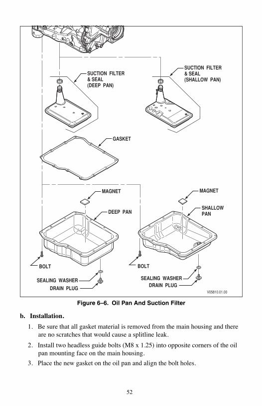
52
Figure 6–6. Oil Pan And Suction Filter
b. Installation.
1. Be sure that all gasket material is removed from the main housing and there are no scratches that would cause a splitline leak.
2. Install two headless guide bolts (M8 x 1.25) into opposite corners of the oil pan mounting face on the main housing.
3. Place the new gasket on the oil pan and align the bolt holes.
V05810.01.00
SEALING WASHER SEALING WASHER
DEEP PANSHALLOWPAN
GASKET
MAGNET MAGNET
SUCTION FILTER& SEAL(SHALLOW PAN)
SUCTION FILTER& SEAL(DEEP PAN)
DRAIN PLUG DRAIN PLUG
BOLT BOLT

53
4. Slide the oil pan gasket and oil pan over the guide bolts and hold them in place while installing two of the bolts to hold the parts in place.
5. Install the remainder of the 12 bolts that fasten the oil pan to the main housing (two will replace the guide bolts). Tighten the bolts to 24–29 N·m (18–21 lb ft).
6. Reinstall the drain plug and sealing washer. Tighten the drain plug to 30–40 N·m (22–30 lb ft).
7. Replace the quantity of transmission fluid lost during the gasket replacement process. Refer to MT3190EN for fluid fill and check procedures.
6–8. SUCTION FILTER AND SEAL REPLACEMENT
Use the following procedure for removal and installation of the suction filter and seal. Replacement is usually not necessary except at overhaul (see Figure 6–6).
a. Removal.
1. Remove the drain plug and sealing washer from the oil pan and allow the fluid to drain into a suitable container. Examine the fluid as described in MT3190EN.
2. Remove the 12 bolts that fasten the oil pan to the main housing. Hold the oil pan in position as the last bolt is removed.
3. Remove the oil pan and oil pan gasket. Check the magnet in the oil pan. Be sure that excessive or large metallic particles are not present. These conditions would indicate that an overhaul may be required.
4. Remove the suction filter by pulling straight down where the suction tube is seated in the main housing.
5. Remove the suction seal from the filter or from the seal bore in the main housing. Discard the old seal and the filter, if it is being replaced.
b. Installation.
1. Place a new seal on the suction filter tube. The seal should locate against a shoulder on the suction filter tube.
2. Push the filter and seal into the seal bore in the main housing. Be sure the suction filter is properly positioned.
NOTE: It would be helpful to know how much transmission fluid is lost during the replacement of the suction filter and seal. Fluid in good condition caught in a clean container may be reused.
CAUTION: If a shallow pan and filter were removed, reinstall a shallow pan and filter. If a deep pan and filter were removed, reinstall a deep pan and filter. Transmission damage can occur if the correct oil pan and filter are not installed.

54
3. Be sure that all gasket material is removed from the main housing and there are no scratches that would cause a splitline leak.
4. Install two headless guide bolts (M8 x 1.25) into opposite corners of the oil pan mounting face on the main housing.
5. Place a gasket on the oil pan and align the bolt holes.
6. Slide the oil pan gasket and oil pan over the guide bolts and hold them in place while installing two of the bolts to hold the parts in place.
7. Install the remainder of the 12 bolts that fasten the oil pan to the main housing (two will replace the guide bolts). Tighten the bolts to 24–29 N·m (18–21 lb ft).
8. Reinstall the drain plug and sealing washer. Tighten the drain plug to 30–40 N·m (22–30 lb ft).
9. Replace the quantity of transmission fluid lost during the suction filter and seal replacement process. Refer to MT3190EN for fluid fill and check procedures.
6–9. CONTROL VALVE COMPONENT REPLACEMENT
The control valve components that will be covered as in-chassis repairs are the internal wiring harness, the pressure switch manifold assembly, the solenoids, and the internal detent lever assembly. These components are typically replaced after a diagnostic process has been completed and a faulty component was identified.
a. Internal Wiring Harness Replacement. Use the following procedure to replace the internal wiring harness.
1. Remove the drain plug and sealing washer from the oil pan and allow the fluid to drain into a suitable container (see Figure 6–6). Examine the fluid as de-scribed in MT3190EN.
2. Remove the 12 bolts that fasten the oil pan to the main housing. Hold the oil pan in position as the last bolt is removed.
3. Remove the oil pan and oil pan gasket. Check the magnet in the oil pan (see Figure 6–6). Be sure that excessive or large metallic particles are not present. These conditions would indicate that an overhaul may be required.
4. Remove the suction filter by pulling straight down where the suction tube is seated in the main housing.
5. Remove the suction seal from the filter or from the seal bore in the main housing. Discard the old seal and the filter, if it is being replaced.
NOTE: It would be helpful to know how much transmission fluid is lost during the replacement of the internal harness. Fluid in good condition caught in a clean container may be reused.

55
6. Disconnect the external wiring harness from the main transmission electrical connector.
7. Disconnect the internal wiring harness connectors from solenoids A through G (see Figure 6–8) and from the pressure switch manifold assembly.
8. Remove the retaining clips for solenoids E and D which also retain tabs on the wiring harness U-channel (see Figure 6–9). The solenoids will remain in position even after the retaining clips are removed.
9. Remove the main electrical connector (outer end of internal harness) by placing a socket or wrench over the connector to release the “feet” that attach the connector to the main housing (see Figure 6–10) and pushing inward on the connector. Tools which work for this step are 30 mm or 11⁄4 inch 12-point deep sockets or box-end wrenches. Remove the internal wiring harness from the transmission.
10. Place the new internal wiring harness in the approximate position it will occupy after installation.
Figure 6–7. Transmission Main Electrical Connector
NOTE: The transmission main electrical connector is actually one end of the internal harness which protrudes through the main housing (see Figure 6–7).
MAIN ELECTRICAL CONNECTOR(Outer end of internal harness)
RETAINING FEET
V05794

56
Figure 6–8. Control Valve Solenoid Location
Figure 6–9. Internal Wiring Harness Removal/Installation
11. Push the main electrical connector outward through the hole in the main housing. Use special tool J 44247 to make sure the retaining feet seat the connector in the main housing (see Figure 6–7).
12. Align the tabs on the wiring harness U-channel with the retaining clip slots for solenoids E and D on the control valve body. Install the retaining clips for the E and D solenoids (see Figures 6–8 and 6–9).
V07476.02.00
ED
F
B TRIMA TRIM
C
G
HARNESS CONNECTORS
SOLENOID CONNECTORS
SOLENOID RETAINING CLIPS
V05792
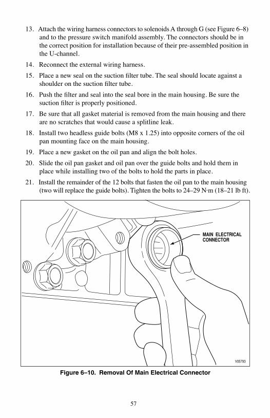
57
13. Attach the wiring harness connectors to solenoids A through G (see Figure 6–8) and to the pressure switch manifold assembly. The connectors should be in the correct position for installation because of their pre-assembled position in the U-channel.
14. Reconnect the external wiring harness.
15. Place a new seal on the suction filter tube. The seal should locate against a shoulder on the suction filter tube.
16. Push the filter and seal into the seal bore in the main housing. Be sure the suction filter is properly positioned.
17. Be sure that all gasket material is removed from the main housing and there are no scratches that would cause a splitline leak.
18. Install two headless guide bolts (M8 x 1.25) into opposite corners of the oil pan mounting face on the main housing.
19. Place a new gasket on the oil pan and align the bolt holes.
20. Slide the oil pan gasket and oil pan over the guide bolts and hold them in place while installing two of the bolts to hold the parts in place.
21. Install the remainder of the 12 bolts that fasten the oil pan to the main housing (two will replace the guide bolts). Tighten the bolts to 24–29 N·m (18–21 lb ft).
Figure 6–10. Removal Of Main Electrical Connector
MAIN ELECTRICAL CONNECTOR
V05793

58
22. Reinstall the drain plug and sealing washer. Tighten the drain plug to 30–40 N·m (22–30 lb ft).
23. Replace the quantity of transmission fluid lost during the internal harness replacement process. Refer to MT3190EN for fluid check procedures.
b. Pressure Switch Manifold Assembly Replacement. Use the following proce-dure to replace the pressure switch manifold assembly.
1. Remove the drain plug and sealing washer from the oil pan and allow the fluid to drain into a suitable container (see Figure 6–6). Examine the fluid as de-scribed in MT3190EN.
2. Remove the 12 bolts that fasten the oil pan to the main housing. Hold the oil pan in position as the last bolt is removed.
3. Remove the oil pan and oil pan gasket. Check the magnet in the oil pan (see Figure 6–6). Be sure that excessive or large metallic particles are not present. These conditions would indicate that an overhaul may be required.
4. Remove the suction filter by pulling straight down where the suction tube is seated in the main housing.
5. Remove the suction seal from the filter or from the seal bore in the main housing. Discard the old seal and the filter, if it is being replaced.
6. Remove the two bolts that fasten the reverse signal tube to the control valve body (see Figure 6–11). Remove the reverse signal tube.
7. Remove the five bolts that attach the pressure switch manifold assembly to the control valve body. Remove the pressure switch manifold assembly from the transmission.
8. Inspect the valve body for O-ring seals that may have been left from an old pressure switch assembly. Remove any old O-rings found.
9. Place the new pressure switch manifold assembly in position and install one bolt in a recessed location to hold it into position. Start the remaining four bolts in recessed locations and tighten them all by hand. Torque the bolts to 10–13 N·m (7–10 lb ft). The one remaining bolt will be installed following the reverse signal tube.
10. Connect the internal wiring harness connector to the pressure switch manifold assembly.
NOTE: It would be helpful to know how much transmission fluid is lost during the replacement of the pressure switch manifold assembly. Fluid in good condition caught in a clean container may be reused.
NOTE: Individual pressure switches cannot be replaced. When any pressure switch needs replacing, the entire assembly must be replaced.

59
Figure 6–11. Pressure Switch Manifold Assembly Replacement
11. Install the reverse signal tube. Install the two bolts that fasten the reverse signal tube to the control valve body (see Figure 6–11). Tighten the bolts to 10–13 N·m (7–10 lb ft).
12. Place a new seal on the suction filter tube. The seal should locate against a shoulder on the suction filter tube.
13. Push the filter and seal into the seal bore in the main housing. Be sure the suction filter is properly positioned.
14. Be sure that all gasket material is removed from the main housing and there are no scratches that would cause a splitline leak.
15. Install two headless guide bolts (M8 x 1.25) into opposite corners of the oil pan mounting face on the main housing.
16. Place a gasket on the oil pan and align the bolt holes.
17. Slide the oil pan gasket and oil pan over the guide bolts and hold them in place while installing two of the bolts to hold the parts in place.
18. Install the remainder of the 12 bolts that fasten the oil pan to the main housing (two will replace the guide bolts). Tighten the bolts to 24–29 N·m (18–21 lb ft).
19. Reinstall the drain plug and sealing washer. Tighten the drain plug to 30–40 N·m (22–30 lb ft).
20. Replace the quantity of transmission fluid lost during the pressure switch manifold assembly replacement process. Refer to MT3190EN for fluid check procedures.
TUBE RETAINING BOLT LOCATIONS
WIRING HARNESSCONNECTOR
REVERSESIGNAL
TUBE
PRESSURE SWITCH MANIFOLD ASSEMBLY
VO5791.01.00

60
c. Solenoid A, B, D, E, or F Replacement. Use the following procedure to replace any solenoid except C and G.
1. Remove the drain plug and sealing washer from the oil pan and allow the fluid to drain into a suitable container (see Figure 6–6). Examine the fluid as de-scribed in MT3190EN.
2. Remove the 12 bolts that fasten the oil pan to the main housing. Hold the oil pan in position as the last bolt is removed.
3. Remove the oil pan and oil pan gasket. Check the magnet in the oil pan (see Figure 6–6). Be sure that excessive or large metallic particles are not present. These conditions would indicate that an overhaul may be required.
4. Remove the suction filter by pulling straight down where the suction tube is seated in the main housing.
5. Remove the suction seal from the filter or from the seal bore in the main housing. Discard the old seal and the filter, if it is being replaced.
6. Disconnect the internal wiring harness from the solenoid being changed.
7. To remove A or B solenoid, remove three bolts and the solenoid retaining bracket. To remove solenoids E, D, or F, remove the solenoid retaining clip (see Figure 6–8 or 6–9).
8. Note the position of the solenoid connector and pull the solenoid out of the bore in the control valve body. The O-rings on the solenoid provide the resistance felt during removal.
9. Obtain the new solenoid. Lubricate the O-rings with clean transmission fluid. Push the new solenoid into the control valve body bore with the wiring harness connector in the same position as when the solenoid was removed.
NOTE: It would be helpful to know how much transmission fluid is lost during the replacement of any solenoid. Fluid in good condition caught in a clean container may be reused.
NOTE: When the A and B solenoid retaining bracket is removed, there are two sets of accumulators and springs which will probably fall from their bores. When reinstalling the parts, the valve goes in the bore first with the hollow end facing outward, followed by the spring which goes inside the hollow portion of the valve.
NOTE: The A and B solenoid bracket must not be modified. Note that the angle between the two bracket surfaces is less than 90 degrees (see Figure 6–12). Gently bend the bracket to less than 90 degrees.

61
10. Reinstall the two accumulators and springs before installing the A and B solenoid retaining bracket (see NOTE following Step 6 above). Reinstall the solenoid retaining clip or bracket. Tighten the three bolts which hold the A and B solenoid retaining bracket to 10–13 N·m (7–10 lb ft).
11. Reconnect the internal wiring harness to the solenoid.
12. Place a new seal on the suction filter tube. The seal should locate against a shoulder on the suction filter tube.
13. Push the filter and seal into the seal bore in the main housing. Be sure the suction filter is properly positioned so that the oil pan will clear it and hold it in position.
14. Be sure that all gasket material is removed from the main housing and there are no scratches that would cause a splitline leak.
15. Install two headless guide bolts (M8 x 1.25) into opposite corners of the oil pan mounting face on the main housing.
16. Place a gasket on the oil pan and align the bolt holes.
17. Slide the oil pan gasket and oil pan over the guide bolts and hold them in place while installing two of the bolts to hold the parts in place.
18. Install the remainder of the 12 bolts that fasten the oil pan to the main housing (two will replace the guide bolts). Tighten the bolts to 24–29 N·m (18–21 lb ft).
19. Reinstall the drain plug and sealing washer. Tighten the drain plug to 30–40 N·m (22–30 lb ft).
20. Replace the quantity of transmission fluid lost during the solenoid replacement process. Refer to MT3190EN for fluid fill and check procedures.
Figure 6–12. Solenoid A And B Retaining Bracket
LESS THAN 90°BY DESIGN
V05813

62
d. Solenoid C Replacement. Use the following procedure to replace the C sole-noid. The control valve body must be completely removed from the transmission.
1. Remove the drain plug and sealing washer from the oil pan and allow the fluid to drain into a suitable container (see Figure 6–6). Examine the fluid as described in MT3190EN.
2. Remove the 12 bolts that fasten the oil pan to the main housing. Hold the oil pan in position as the last bolt is removed.
3. Remove the oil pan and oil pan gasket. Check the magnet in the oil pan (see Figure 6–6). Be sure that excessive or large metallic particles are not present. These conditions may indicate that an overhaul is required.
4. Remove the suction filter by pulling straight down where the suction tube is seated in the main housing.
5. Remove the suction seal from the filter or from the seal bore in the main housing. Discard the old seal and the filter, if it is being replaced.
6. Release the main electrical connector from the main housing as described in Sub-paragraph a., Steps 6 and 9 of Section 6–9. This allows the internal wiring harness to remain with the control valve body as it is removed.
7. Remove fifteen bolts at locations marked “A” and “B” (see Figure 6–13). Be ready to support the weight of the control valve body (about 10 pounds) as the last bolt is removed. Remove the control valve body assembly from the dowel pins in the main housing. When the valve body assembly has cleared the dowel pins, move it sideways to disengage the pin in the manual selector valve from the slot in the detent lever. Remove the control valve body assembly.
8. Remove the wiring harness connector from C solenoid. Remove the retaining clip for the C solenoid (see Figure 6–8).
9. Note the position of the solenoid connector and pull the solenoid out of the bore in the control valve body. The O-rings on the solenoid provide the resistance felt during removal.
10. Obtain the new solenoid. Lubricate the O-rings with clean transmission fluid. Push the new solenoid into the control valve body bore with the wiring harness connector in the correct position.
NOTE: It would be helpful to know how much transmission fluid is lost during the replacement of solenoid C. Fluid in good condition caught in a clean container may be reused.
NOTE: As the control valve body is removed, be careful not to lose the manual selector valve pin or allow the manual selector to slide out.

63
11. Reconnect the internal harness to solenoid C. Reinstall the solenoid retaining clip.
12. Move the control valve assembly into position under the main housing. Engage the pin in the manual selector valve into the slot in the detent lever. Align the valve body assembly with the dowel pins in the main housing, seat the body assembly against the main housing and install one bolt to hold the assembly in place. Reinstall the remaining fourteen “A” and “B” bolts (see Figure 6–13) that fasten the control valve body assembly to the main housing. Tighten the bolts to 10–13 N·m (7–10 lb ft).
13. Push the main electrical connector outward through the hole in the main housing. Use tool J 44247 to make sure the retaining feet seat the connector in the main housing (see Figure 6–7). Connect the internal wiring harness.
14. Place a new seal on the suction filter tube. The seal should locate against a shoulder on the suction filter tube.
15. Push the filter and seal into the seal bore in the main housing. Be sure the suction filter is properly positioned so that the oil pan will clear it and hold it in place.
16. Be sure that all gasket material is removed from the main housing and there are no scratches that would cause a splitline leak.
17. Install two headless guide bolts (M8 x 1.25) into opposite corners of the oil pan mounting face on the main housing.
18. Place the gasket on the oil pan and align the bolt holes.
19. Slide the oil pan gasket and oil pan over the guide bolts and hold them in place while installing two of the bolts to hold the parts in place.
20. Install the remainder of the 12 bolts that fasten the oil pan to the main housing (two will replace the guide bolts). Tighten the bolts to 24–29 N·m (18–21 lb ft).
21. Reinstall the drain plug and sealing washer. Tighten the drain plug to 30–40 N·m (22–30 lb ft).
22. Replace the quantity of transmission fluid lost during the solenoid replacement process. Refer to MT3190EN for fluid fill and check procedures.

64
e. Solenoid G Replacement.
1. Remove the drain plug and sealing washer from the oil pan and allow the fluid to drain into a suitable container (see Figure 6–6). Examine the fluid as described in MT3190EN.
2. Remove the 12 bolts that fasten the oil pan to the main housing. Hold the oil pan in position as the last bolt is removed.
3. Remove the oil pan and oil pan gasket. Check the magnet in the oil pan (see Figure 6–6). Be sure that excessive or large metallic particles are not present. These conditions may indicate that an overhaul is required.
4. Remove the suction filter by pulling straight down where the suction tube is seated in the main housing.
5. Remove the suction seal from the filter or from the seal bore in the main housing. Discard the old seal and the filter, if it is being replaced.
6. Disconnect the wiring harness from Solenoid G.
7. Remove six bolts retaining the G solenoid valve body to the control valve body.
8. Remove the G solenoid valve body.
9. Turn the G solenoid valve body hydraulic passages up.
10. Remove the solenoid retainer clip.
11. Remove G solenoid from the valve body.
12. Lubricate the O-rings on the replacement solenoid.
13. Install Solenoid G into the valve body, electrical connector pointing towards the pressure manifold and parallel to the valve body so that the connector is horizontal when installed in the vehicle.
14. Install the solenoid retainer
15. Install six M6 x 1.5 x 65 mm bolts that retain the modulated main valve body to the main valve body. Tighten bolts to 10–13 N·m (7–10 lb ft).
16. Connect the internal wiring harness.
17. Place a new seal on the suction filter tube. The seal should locate against a shoulder on the suction filter tube.
18. Push the filter and seal into the seal bore in the main housing. Be sure the suction filter is properly positioned so that the oil pan will clear it and hold it in place.
19. Be sure that all gasket material is removed from the main housing and there are no scratches that would cause a splitline leak.
20. Install two headless guide bolts (M8 x 1.25) into opposite corners of the oil pan mounting face on the main housing.
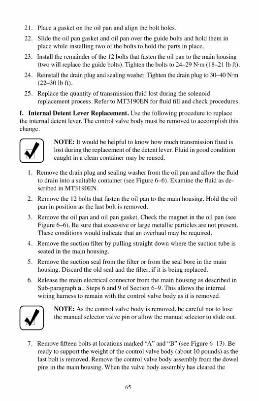
65
21. Place a gasket on the oil pan and align the bolt holes.
22. Slide the oil pan gasket and oil pan over the guide bolts and hold them in place while installing two of the bolts to hold the parts in place.
23. Install the remainder of the 12 bolts that fasten the oil pan to the main housing (two will replace the guide bolts). Tighten the bolts to 24–29 N·m (18–21 lb ft).
24. Reinstall the drain plug and sealing washer. Tighten the drain plug to 30–40 N·m (22–30 lb ft).
25. Replace the quantity of transmission fluid lost during the solenoid replacement process. Refer to MT3190EN for fluid fill and check procedures.
f. Internal Detent Lever Replacement. Use the following procedure to replace the internal detent lever. The control valve body must be removed to accomplish this change.
1. Remove the drain plug and sealing washer from the oil pan and allow the fluid to drain into a suitable container (see Figure 6–6). Examine the fluid as de-scribed in MT3190EN.
2. Remove the 12 bolts that fasten the oil pan to the main housing. Hold the oil pan in position as the last bolt is removed.
3. Remove the oil pan and oil pan gasket. Check the magnet in the oil pan (see Figure 6–6). Be sure that excessive or large metallic particles are not present. These conditions would indicate that an overhaul may be required.
4. Remove the suction filter by pulling straight down where the suction tube is seated in the main housing.
5. Remove the suction seal from the filter or from the seal bore in the main housing. Discard the old seal and the filter, if it is being replaced.
6. Release the main electrical connector from the main housing as described in Sub-paragraph a., Steps 6 and 9 of Section 6–9. This allows the internal wiring harness to remain with the control valve body as it is removed.
7. Remove fifteen bolts at locations marked “A” and “B” (see Figure 6–13). Be ready to support the weight of the control valve body (about 10 pounds) as the last bolt is removed. Remove the control valve body assembly from the dowel pins in the main housing. When the valve body assembly has cleared the
NOTE: It would be helpful to know how much transmission fluid is lost during the replacement of the detent lever. Fluid in good condition caught in a clean container may be reused.
NOTE: As the control valve body is removed, be careful not to lose the manual selector valve pin or allow the manual selector to slide out.

66
dowel pins, move it sideways to disengage the pin in the manual selector valve from the slot in the detent lever. Remove the control valve body assembly.
8. Loosen the nut on the selector shaft that is retaining the internal detent lever to the selector shaft (see Figure 6–14).
9. Place a protective plate on the main housing surface around the spring pin. Place a drill bit into the spring pin to prevent cutting or collapsing the pin when removing the pin. Remove the spring pin from the main housing.
10. Slide the selector shaft through the detent lever and through the selector shaft seal and remove the detent lever and nut.
11. Place the new detent lever in position in the main housing. Reinstall the selector shaft through the selector shaft seal and through the detent lever. Place the detent lever retaining nut in position over the selector shaft. Push the selector shaft into its final position in the main housing.
12. Reinstall the spring pin into the main housing that retains the selector shaft. If available, use tool J 43766 to install the spring pin. If tool is not available, install pin to 8.5–9.0 mm above main housing surface. Tighten the detent lever retaining nut on the selector shaft.
13. Move the control valve assembly into position under the main housing. Engage the pin in the manual selector valve into the slot in the detent lever. Align the valve body assembly with the dowel pins in the main housing, seat the body assembly against the main housing and install one bolt to hold the assembly in place. Reinstall the remaining fourteen bolts at “A” and “B” (see Figure 6–13) that fasten the control valve body assembly to the main housing. Tighten the bolts to 10–13 N·m (7–10 lb ft).
14. Push the main electrical connector outward through the hole in the main housing. Use tool J 44247 to properly seat the retaining feet to retain the connector in the main housing (see Figure 6–7). Connect the internal wiring harness.
15. Place a new seal on the suction filter tube. The seal should locate against a shoulder on the suction filter tube.
16. Push the filter and seal into the seal bore in the main housing. Be sure the suction filter is properly positioned so that the oil pan will clear it and hold it in place.
NOTE: DO NOT mar the main housing surface around the spring pin when removing the spring pin. An unmarred surface is required to maintain the seal between the control valve body assembly and the main housing.

67
17. Be sure that all gasket material is removed from the main housing and there are no scratches that would cause a splitline leak.
18. Install two headless guide bolts (M8 x 1.25) into opposite corners of the oil pan mounting face on the main housing.
19. Place a gasket on the oil pan and align the bolt holes.
20. Slide the oil pan gasket and oil pan over the guide bolts and hold them in place while installing two of the bolts to hold the parts in place.
21. Install the remainder of the 12 bolts that fasten the oil pan to the main housing (two will replace the guide bolts). Tighten the bolts to 24–29 N·m (18–21 lb ft).
22. Reinstall the drain plug and sealing washer. Tighten the drain plug to 30–40 N·m (22–30 lb ft).
23. Replace the quantity of transmission fluid lost during the solenoid replacement process. Set the transmission fluid level following the procedure in MT3190EN.
Figure 6–13. Control Valve Body Removal
A
A
A
A
A
A
BB
B
B
A
AA
A
A
V05814.01.00

68
Figure 6–14. Detent Lever Replacement
6–10. FRONT SEAL REPLACEMENT
Use the following procedure for removal and installation of the front seal which is in the oil pump inside the converter housing. Replacement of the front seal requires removal of the transmission from the vehicle and removal and reinstallation of the torque converter.
a. Removal.
1. Refer to Section II in MT3190EN for instructions to remove the transmission from the vehicle.
2. Position the transmission vertically with the torque converter end up.
3. Take the measurement described in the NOTE above.
4. Attach a three-strand sling to the torque converter. Lift the torque converter from the transmission and set it safely aside until needed at reassembly.
5. Obtain special tool J 24171-A and install the tip with a 90 degree hook onto the end of the slide-hammer.
6. Position the 90 degree hook behind the rear face of the seal outer case (see Figure 6–15).
7. Remove the front seal using the slide-hammer.
NOTE: Measure the distance from the torque converter mounting lugs to the transmission mounting face. This is an important measurement required to check correct reassembly of the torque converter.
SELECTOR SHAFT
DETENT LEVER NUT
DETENT LEVER
V05815
MAIN HOUSING
SPRINGPIN

69
b. Installation.
1. Inspect the seal bore for scratches. Inspect the seal removed to see the reason for a leak. Worn lip? Broken garter spring? Remove any scratches in the seal bore using crocus cloth.
2. Install the new seal onto the J 43772 installer tool. Position the seal so the seal lip is outward and the face of the steel case is against the driving face of the tool (see Figure 6–16).
3. Slide the installer tool over the turbine shaft and ground sleeve until the seal starts into the seal bore. Strike the installer tool with a mallet to drive the seal into the seal bore (see Figure 6–17). The seal is installed correctly when the shoulder of the installer tool squarely contacts the outer surface of the oil pump.
4. Inspect the converter hub for damage, scratches or machine type leading. Scratches or machine type leading can cause the seal to leak. Remove minor scoring with crocus cloth.
5. Lubricate the converter pump hub OD and the front seal with clean transmission fluid.
6. Use the three-strand sling to lower the torque converter over the turbine shaft and ground sleeve. Remove the three-strand sling. Spin the torque converter to engage the turbine shaft splines in the torque converter hub, the ground sleeve splines in the stator race and the drive flats on the converter pump hub engage the oil pump drive gear.
7. The torque converter is correctly installed when the same measurement taken in Step a.3 above is obtained.
8. Install the torque converter retaining bracket.
9. Reinstall the transmission following instructions in Section V in MT3190EN.
Figure 6–15. Front Seal Removal
V05788
FRONT SEAL OUTER CASE
J 24171-ASPECIAL TOOL

70
Figure 6–16. Positioning New Seal On Installer Tool
Figure 6–17. Installing Front Seal
SEAL LIP (OUTWARD)
J 43772 INSTALLER TOOL
Place flat steel face of seal against this face
V05789
MALLET
J 43772 INSTALLATION TOOL
V05790

71
6–11. COOLER FLUSHING
Metal contamination requires complete transmission disassembly and cleaning. Clean all internal and external hydraulic circuits, transmission cooler, and all areas where metal and other particles could lodge. Special tool J 46550 Transmission Cooler Kwik-Flush Cart is now an essential tool for all overhaul and maintenance service outlets, J 46550 or an approved cooler flushing device that meets Allison cooler flushing requirements and procedures must be used.
1. Flush contaminated fluid from the cooler by flowing transmission fluid through the cooler in the reverse direction of normal flow. Use a flushing pump that pumps fluid in a pulsating flow at a minimum mean rate of 0.5 liters/sec (8.0 gpm) and 275–345 kPa (40–50 psi). The J 46550 Transmission Cooler Kwik-Flush Cart meets these requirements.
2. After flushing the contaminated fluid, use the flushing pump to circulate clean transmission fluid through the cooler in a closed loop back to a 10-micron filter. Circulate fluid in the closed loop for a minimum of five minutes.
CAUTION: After flushing the cooler, be sure to check the external cooler circuit restriction. If circuit pressure drop is above specification, the cooler has excessive trapped particles and must be replaced.

72
7–1. OWNER ASSISTANCE
There are distributors and dealers around the world ready to stand behind every Allison Transmission product. Any situation that arises in connection with the sale, operation, or service of your transmission will be handled by the distributor or dealer in your area. Technical support is available from the Technical Assistance Center (TAC) by telephone at 1-800-252-5283.
Refer to the Allison Transmission website
www.allisontransmission.com
or to the Worldwide Sales and Service Directory SA2229EN for a current listing of Allison Transmission authorized distributors and service dealers.
7–2. SERVICE LITERATURE
This service literature provides fully illustrated instructions for operation, maintenance, service, overhaul, and parts support for your transmission. For maximum performance and service life from your unit, see your dealer or distributor for the following publications. Check the telephone directory for the Allison Transmission service outlet nearest you.
Table 7–1. Service Literature
Service Manual SM3191EN
*Parts Catalog PC3062EN CD3062EN
Electronic Troubleshooting Manual TS3192EN
Principles of Operation PO3065EN
*Mechanic’s Tips MT3190EN
*EVS Operator’s Manual OM3761EN
*HS Operator’s Manual OM3757EN
*RDS Operator’s Manual OM3759EN
*MHS Operator’s Manual OM3364EN
*PTS Operator’s Manual OM3758EN
*BUS Operator’s Manual OM3765EN
*1000, 2000, 2400 Operator’s Manual OM3063EN
* Also Available On The Internet At
www.allisontransmission.com
CUSTOMERSERVICE
S
ECTION
VII

JA3664EN 200404 Printed in USA 200405www.allisontransmission.com