Embed Size (px)
Citation preview
4
Hydro-Pneumat ic Power Too l
Genes is® G4
I ns t ruc t i on Manua l


3
Contents
Safety Rules 4
SpecificationsTool Specifications 5Tool Dimensions 5
Intent of UseRange of Fasteners 6Part Numbering 6
Putting into ServiceAir Supply 7Operating Procedure 7Adjusting Vacuum Extraction 7
Nose AssembliesNose Tips 8-10Fitting Instructions 8Fitting Instructions for Maxlok® and Avtainer® 11Servicing Instructions for all Nose Assemblies 11
AccessoriesStem Deflector 12Extension 12Side Ejector 12
Servicing the ToolDaily / Weekly / Monthly 13Moly Lithium Grease EP 3753 Safety Data 13MolyKote 55m & MolyKote 111 Safety Data 14Annually 15Service Kit 15Head Assembly 15-16Pneumatic Piston Assembly 16Valve Spool Assembly 16Trigger 16
General Assembly of Base ToolsGeneral Assembly and Parts List 18-19
PrimingOil Details 20Hyspin VG 32 Safety Data 20Priming Kit 20Priming Procedure 21
Fault DiagnosisSymptom, Possible Cause & Remedy 22-23
Avdel UK Limited policy is one of continuous product development and improvement and we reserve the right to change the specification of any product without prior notice.
WarrantyAvdel installation tools carry a 12 month warranty against defects caused by faultymaterials or workmanship, the warranty period commencing from the date of deliveryconfirmed by invoice or delivery note.
The warranty applies to the user/purchaser when sold through an authorised outlet, andonly when used for the intended purpose. The warranty is invalidated if the installation toolis not serviced, maintained and operated according to the instructions contained in theInstruction and Service Manuals.
In the event of a defect or failure, and at its sole discretion, Avdel undertakes only to repairor replace faulty components.
4
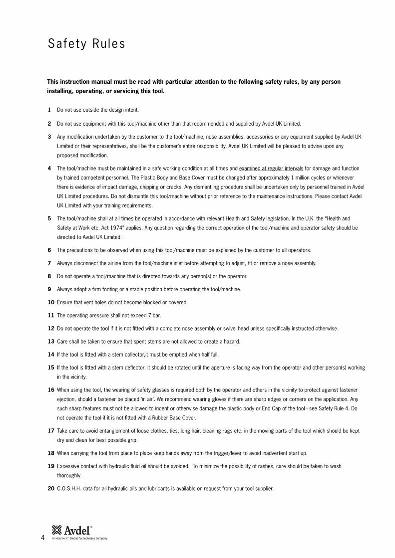
Sa fe ty Ru les
1 Do not use outside the design intent.
2 Do not use equipment with this tool/machine other than that recommended and supplied by Avdel UK Limited.
3 Any modification undertaken by the customer to the tool/machine, nose assemblies, accessories or any equipment supplied by Avdel UK
Limited or their representatives, shall be the customer’s entire responsibility. Avdel UK Limited will be pleased to advise upon any
proposed modification.
4 The tool/machine must be maintained in a safe working condition at all times and examined at regular intervals for damage and function
by trained competent personnel. The Plastic Body and Base Cover must be changed after approximately 1 million cycles or whenever
there is evidence of impact damage, chipping or cracks. Any dismantling procedure shall be undertaken only by personnel trained in Avdel
UK Limited procedures. Do not dismantle this tool/machine without prior reference to the maintenance instructions. Please contact Avdel
UK Limited with your training requirements.
5 The tool/machine shall at all times be operated in accordance with relevant Health and Safety legislation. In the U.K. the “Health and
Safety at Work etc. Act 1974” applies. Any question regarding the correct operation of the tool/machine and operator safety should be
directed to Avdel UK Limited.
6 The precautions to be observed when using this tool/machine must be explained by the customer to all operators.
7 Always disconnect the airline from the tool/machine inlet before attempting to adjust, fit or remove a nose assembly.
8 Do not operate a tool/machine that is directed towards any person(s) or the operator.
9 Always adopt a firm footing or a stable position before operating the tool/machine.
10 Ensure that vent holes do not become blocked or covered.
11 The operating pressure shall not exceed 7 bar.
12 Do not operate the tool if it is not fitted with a complete nose assembly or swivel head unless specifically instructed otherwise.
13 Care shall be taken to ensure that spent stems are not allowed to create a hazard.
14 If the tool is fitted with a stem collector,it must be emptied when half full.
15 If the tool is fitted with a stem deflector, it should be rotated until the aperture is facing way from the operator and other person(s) working
in the vicinity.
16 When using the tool, the wearing of safety glasses is required both by the operator and others in the vicinity to protect against fastener
ejection, should a fastener be placed ‘in air’. We recommend wearing gloves if there are sharp edges or corners on the application. Any
such sharp features must not be allowed to indent or otherwise damage the plastic body or End Cap of the tool - see Safety Rule 4. Do
not operate the tool if it is not fitted with a Rubber Base Cover.
17 Take care to avoid entanglement of loose clothes, ties, long hair, cleaning rags etc. in the moving parts of the tool which should be kept
dry and clean for best possible grip.
18 When carrying the tool from place to place keep hands away from the trigger/lever to avoid inadvertent start up.
19 Excessive contact with hydraulic fluid oil should be avoided. To minimize the possibility of rashes, care should be taken to wash
thoroughly.
20 C.O.S.H.H. data for all hydraulic oils and lubricants is available on request from your tool supplier.
This instruction manual must be read with particular attention to the following safety rules, by any personinstalling, operating, or servicing this tool.

Tool Spec i f icat ion
Too l D imens ions
Spec i f ica t ions
5
Air Pressure Minimum - Maximum 5-7 bar
Free Air Volume Required @ 5.5 bar 4.3 litres
Stroke Minimum 17 mm
Pull Force @ 5.5 bar 18.68 kN
Cycle time Approximately 1.5 seconds
Noise Level 75 dB(A)
Weight Without nose equipment 1.64 kg
Vibration Less than 2.5 m/s2
Vibration Utilising 1/4 STL Lockbolt equip 3.58 m/s2
Dimensions in millimetres.
30
12°30'
134
128
152
150
316
145
116
70
4

6
I n ten t o f Use
G4 is a hydro-pneumatic tool designedto place Avdel® breakstem fasteners athigh speed making it ideal for batch orflow-line assembly in a wide variety ofapplications throughout light / mediumindustries where the plastic componentswill not be subject to impact damage. Itcan place all fasteners listed opposite.
The tool features an adjustable vacuumsystem for fastener retention and troublefree collection of the spent stemsregardless of tool orientation. See the‘Operating Procedure’ on page 7 foradjustment instructions.
A complete tool is made up of threeseparate elements which will be suppliedindividually. See diagram below.
NOSE EQUIPMENT MUST BE FITTEDAS DESCRIBED ON PAGES 8-11.
FASTENERNAME
MMINFASTENER SIZE ( )
AVEX®
STAVEX®
AVINOX®
AVIBULB®
BULBEX®
T-LOK®
AVDEL® SRINTERLOCK®
HEMLOK®
TLR®
MAXLOK®
AVTAINER®
AVDEL®
MBCMBC/LCAVSEAL®
QTM RIVETTTM RIVET
CHERRYMATETM
4.3 4.8 5 5.2 6 6.4 6.5 7 8 9 9.5 10
– 3/16 – – – 1/4 – – – – 3/8 –! !
! !
!
! !
!
! !
! !
! !
!
! !
! !
!
!
!
!
! ! !
! !
! !
! !
COMPLETE TOOL71230-00 . . . *
BASE TOOL
NOSE ASSEMBLY
NOSE TIP
71230-02000
71210-15000
see note 3 + + =
4 4
1
1
2
3
1 22
33
The part number of the base tool remains the same whichever nose assembly, or nose tip is fitted. See the General Assemblypages 18-19. If a Maxlok® nose assembly is fitted, the same base tool MUST be adapted. See details page 11.
The nose tip part number relates to a specific fastener. If access to the application isrestricted, some extended nose tips are available. See ‘type 2 nose tip’ table page 9.
This single nose assembly will allow placing of non-aerospace fasteners by simply selecting the appropriate nosetip from the range of type 1 nose tips. Other nose assemblies are available for applications with restrictedaccess, for aerospace and special fasteners. See tables pages 8-10.
* ADD 3 DIGITS FROM THELAST COLUMN OF A NOSE TIPTABLE ON PAGE 8, 9 OR 10.FOR MAXLOK®, USE MAXLOK®
TABLE PAGE 10 EVEN THOUGHTHERE IS NO NOSE TIP.
Range of Fasteners
Par t Number ing

Air Supp ly
Operat ing Procedure
Adjus t ing Vacuum Extract ion
Put t ing in to Serv ice
7
All tools are operated with compressed air at an optimum pressure of 5.5 bar. We recommend the use of pressure regulators and filteringsystems on the main air supply. These should be fitted within 3 metres of the tool (see diagram below) to ensure maximum tool life andminimum tool maintenance.
Air supply hoses should have a minimum working effective pressure rating of 150% of the maximum pressure produced in the system or10 bar, whichever is the highest. Air hoses should be oil resistant, have an abrasion resistant exterior and should be armoured whereoperating conditions may result in hoses being damaged. All air hoses MUST have a minimum bore diameter of 6.4 millimetres or 1/4 inch.
Read daily servicing details page 13.
• Using a screwdriver, turn rotary valve 65 until the air flowat the rear of the tool ceases.
• With the nose of the tool pointing downwards, insert afastener other than Avtainer® or Maxlok®, into the noseand hold it into position.
• Turn the rotary valve either way until there is sufficientsuction to retain the fastener.
86
42
0
10121416
TAKE OFF POINTFROMMAIN SUPPLY
STOP COCK(USED DURING MAINTENANCE
OF FILTER/REGULATOR OR LUBRICATION UNITS)
MAIN SUPPLYDRAIN POINT
PRESSURE REGULATORAND FILTER (DRAIN DAILY)
3 METRES MAXIMUM
4
ALL FASTENERS EXCEPT AVTAINER® AND MAXLOK®
• Ensure that a nose assembly suitable for the fastener is fitted(see pages 8-10).
• Connect the tool to the air supply.• Insert the fastener stem into the nose of the tool. The fastener
should remain held in by the vacuum system. If not, adjust thevacuum extraction rotary valve 65 (see note below).
• Bring the tool with the fastener to the application so that theprotruding fastener enters squarely the hole of theapplication.
• Fully actuate the trigger. The tool cycle will broach thefastener and the broken stem will be projected to the rear ofthe tool .
AVTAINER® AND MAXLOK®
• Ensure that the correct nose assembly is fitted.• Connect the tool to the air supply.• Disable the vacuum extraction system by turning rotary valve
65 until you feel or hear no air flow out of the front of thenose assembly.
• Push the Maxlok® or Avtainer® stem through the applicationhole.
• Place the collar on the stem (orientation as shown below).• Keeping the head of the stem against the application, push the
tool onto the protruding stem.• Fully depress the trigger. One cycle will ensure that the collar
is swaged into the lock grooves of the stem and that the stembreaks at the breaker groove.
• Release the trigger. The tool completes its cycle by pushingitself off the collar and the spent stem will be pushed to therear of the tool on insertion of the next fastener.
Item numbers in bold refer to the general assembly drawing and parts list on pages 18-19.
Placing AVTAINER® Placing MAXLOK®

8
Nose Assembl ies
I M P O R T A N TNose assemblies do NOT include nose tips. Nose tips must be ordered separately.
A tool must always be fitted with the correct nose assembly and nose tip for your fastener and must be ordered separately, refer tothe ‘NOSE TIPS’ tables below and pages 9-10.
If your application presents no access restriction use a type 1 nose tip unless you are placing aerospace fasteners which require atype 3 nose tip, Avtainer® a type 5, Hemlok® and 1/4” Interlock® a type 6. Maxlok® requires a special nose assembly which does notmake use of any nose tip, see pages 10-11.Dimensions ‘A’ and ‘B’ will help you assess the suitability of a particular nose tip.You should also check that the dimensions of the nose casing will not restrict access to your application. If access is restricted type 2nose tips with extra reach, are available for some fasteners. Refer to the table on page 9. It is essential that a fastener-compatible nose assembly and nose tip are fitted prior to operating the tool (no nose tip with Maxlok®).
I M P O R T A N T
The air supply must be disconnected when fitting or removing nose assemblies.
See page 9, except for Avtainer® and Maxlok® see page 11.
1 In inches then in millimetres.2 Head forming nose tips for use with countersunk headsONLY.3 Long nose tip for deep placing.4 Material of the body then of the stem. 'Al' is theabbreviation for Aluminium.5 Domehead.6 Countersunk.
T Y P E 1N O S E T I P S
F A S T E N E RMATERIALØ1
N O S E T I P ( m m ) seebelowPART Nº 'A' 'B'NAME
AluminiumAluminiumSteelAluminiumAluminiumSteelSteelStainless SteelSteelSteelAluminiumAluminiumAluminiumAluminiumAluminiumAluminiumAluminiumAluminiumAluminiumStainless SteelSteelSteelSteelSteelAnyAnyAnyAnyAnyAnyAnyAnyAl/Al4Al/Al4Al/Steel4Al/Steel4Al/Al4Al/Al4Al/Steel4Al/Steel4
3/163/163/163/161/4
3/163/163/163/161/4
3/16 ––––––
3/161/4 3/16–
3/16 3/16
–3/161/4 3/163/163/16 1/4
3/16 1/4
3/163/163/163/161/41/41/41/4
2.83.33.34.13.33.32.82.82.82.82.85.57.35.67.35.67.34.14.44.83.33.34.83.35.73.35.72.83.33.33.33.39.58.09.59.0
11.28.0
10.28.3
12.719.012.712.712.719.012.712.712.712.712.712.712.712.712.712.712.712.712.712.712.712.712.712.712.712.712.712.712.712.712.712.715.912.715.912.717.512.716.712.7
07381-0470107340-0480007490-0440107340-066012
07612-0200107381-0470107381-0470107381-0470107340-0480007612-0200107381-0470171220-1600671220-160113
71220-1600771220-160123
71220-1600871220-160133
07605-0022071220-1608007498-0140107340-0620107340-0620107498-0140107612-0200107348-070015
71220-6000171210-160506
07381-0470107340-0620107612-0200107340-0620107612-02001703-A-25-6TA
703-B-21703-A-25-6T
703-B-26743-A-25-8TA
743-B-21743-A-25-8T
743-B-26
4.84.84.84.86.44.84.84.84.86.44.88899
10104.86.44.84.34.84.86
4.86.44.84.84.86.44.86.44.84.84.84.86.46.46.46.4
AVEX®Large flange
STAVEX®Countersunk
Large flange
BULBEX®AVSEAL®
TLR®
AVINOX® IIT-LOK®
AVIBULB®
AVDEL® SR
INTERLOCK®Q™ RIVET
CHERRYMATE®
T™ RIVETLarge flange
Large flange
Large flange
Large flange
… 0 1 0… 0 1 6… 0 1 7… 0 1 5… 0 2 1… 0 1 6… 0 1 0… 0 1 0… 0 1 0… 0 2 1… 0 1 0… 1 6 5… 1 8 5… 1 6 6… 1 8 6… 1 6 7… 1 8 7… 1 4 0… 1 4 1… 0 8 2… 1 2 0… 1 2 0… 0 8 2… 0 2 1… 0 6 2… 0 6 3… 0 6 4… 0 1 0… 1 2 0… 0 2 1… 1 2 0… 0 2 1… 3 8 0… 3 8 1… 3 8 3… 3 8 4… 3 8 5… 3 8 6… 3 8 7… 3 8 8
A
B
ITEM DESCRIPTION PART Nº1 NOSE CASING 07340-003062 'O' RING 07003-000673 JAW HOUSING 07340-003044 JAWS 71210-150015 JAW SPREADER 07498-045026 BUFFER 71210-050017 SPRING 07500-004188 LOCKING RING 07340-00327
COMPLETE TOOLPART NUMBER :
precede with71230-008 7 6 5 4 23 1 61
22.9
N O S E A S S E M B L Ypart nº 71210-15000
F i t t ing Ins t ruct ions
Nose T ips

9
Nose Assembl ies
Item numbers in bold refer to nose assembly components in type 1,2, 3 and 6 nose tip tables.
• Lightly coat jaws 4 with Moly lithium grease*.• Drop jaws 4 into jaw housing 3.• Insert jaw spreader 5 into jaw housing 3.• Locate buffer 6 on jaw spreader 5.• Locate spring 7 onto jaw spreader 5.• Fit locking ring 8 onto the jaw spreader housing.• Holding tool pointing down, screw the assembled jaw housing onto the jaw spreader housing and tighten with spanner*. • Screw the nose tip into nose casing 1 and tighten with spanner*.• Place nose casing 1 with ‘O’ ring 2 over jaw housing 3 and screw onto the tool, tightening with spanner*.
* Item included in the G4 service kit. For complete list see page 15.
1 In inches then in millimetres.
F A S T E N E RMATERIALØ1
N O S E T I P ( m m ) seebelowPART Nº 'A' 'B'NAME
AluminiumSteelAluminiumSteelSteel
3/163/16 3/16
–3/16
10.011.810.010.010.0
12.712.712.712.712.7
07340-0280707340-0730107340-0280707241-0710107241-07101
4.84.84.84.34.8
AVEX®
BULBEX®T-LOK®
… 0 1 4… 0 1 8… 0 1 4… 1 2 1… 1 2 1
ITEM DESCRIPTION PART Nº1 NOSE CASING 07340-028042 'O' RING 07003-000673 JAW HOUSING 07340-003044 JAWS 71210-150015 JAW SPREADER 07498-045026 BUFFER 71210-050017 SPRING 07500-004188 LOCKING RING 07340-00327
COMPLETE TOOLPART NUMBER :
precede with71230-00
N O S E A S S E M B L Ypart nº 71210-15200
A
B
TYPE 2 NOSE TIPS ARE EXTENDEDTO ALLOW ACCESS INTOAPPLICATIONS WHERE TYPE 1NOSE TIPS WILL NOT REACH.
T Y P E 2N O S E T I P S
8 7 6 5 4 23 1 58.3
22.9
T Y P E 3N O S E T I P S
COMPLETE TOOLPART NUMBER :
precede with71230-00
1 56.3
22.9
1 In inches then in millimetres. O OversizeN O S E A S S E M B L Y
part nº 71210-15300
ITEM DESCRIPTION PART Nº1 NOSE CASING 07344-020012 'O' RING 07003-000673 JAW HOUSING 07340-003044 JAWS 71210-150015 JAW SPREADER 07498-045026 BUFFER 71210-050017 SPRING 07500-004188 LOCKING RING 07340-00327
F A S T E N E RMATERIALØ1
N O S E T I P ( m m ) seebelowPART Nº 'A' 'B'NAME
AluminiumAluminium OStainless SteelAnyAny
3/163/163/163/16 3/16
2.52.52.45.14.6
12.712.712.712.712.7
71210-1603671210-1603771220-1603807340-0690107344-04701
4.84.84.84.84.8
AVDEL®
MBCMBC L/C
… 2 9 3… 2 9 4… 2 9 5… 3 1 0… 3 2 0
A
B
8 7 6 5 4 23
TYPE 3 NOSE TIPS ARE SPECIFICALLY
FOR THE AEROSPACE FASTENERS
LISTED ABOVE.
1 In inches then in millimetres.
T Y P E 6N O S E T I P S
F A S T E N E RMATERIALØ1
N O S E T I P ( m m ) seeabovePART Nº 'A' 'B'NAME
AnyAny
1/41/4
3.63.6
14.314.3
07612-0200107612-02001
6.46.4
HEMLOK®
INTERLOCK®… 2 6 1… 2 6 1
A
B ITEM DESCRIPTION PART Nº1 NOSE CASING 07340-003062 'O' RING 07003-000673 JAW HOUSING 07612-020034 JAWS 07612-020025 JAW SPREADER 07498-045026 BUFFER 07498-030037 SPRING 07500-004188 LOCKING RING 07340-00327
COMPLETE TOOLPART NUMBER :
precede with71230-00
8 7 6 5 4 3 1 61
22.9
N O S E A S S E M B L Ypart nº 71230-15800
2
Nose T ips
10
Nose Assembl ies
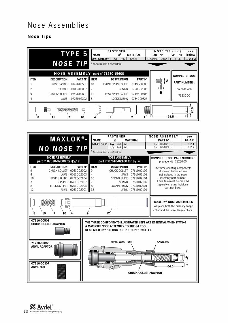
T Y P E 5N O S E T I P
COMPLETE TOOL
PART NUMBER :
precede with
71230-00
1
1 In inches then in millimetres
N O S E A S S E M B L Y part nº 71230-15600
ITEM DESCRIPTION PART Nº
1 NOSE CASING 07498-00501
2 'O' RING 07003-00067
9 CHUCK COLLET 07498-00801
4 JAWS 07220-02302
ITEM DESCRIPTION PART Nº
10 FRONT SPRING GUIDE 07498-00803
7 SPRING 07500-02005
11 REAR SPRING GUIDE 07498-00503
8 LOCKING RING 07340-00327
F A S T E N E RMATERIALØ1
N O S E T I P ( m m ) seebelowPART Nº 'A' 'B'NAME
Steel3/8 4.119.107498-008029.6 … 2 4 3
98.5
20.6
11 7 10 4 298
A
B
AVTAINER®
M A X L O K ®-N O N O S E T I P
12
1 In inches then in millimetres
NOSE ASSEMBLY NOSE ASSEMBLYpart nº 07610-02000 for 3/16 " ø part nº 07610-02100 for 1/4 " ø
ITEM DESCRIPTION PART Nº9 CHUCK COLLET 07610-020024 JAWS 07610-0200310 SPRING GUIDE 07220-021047 SPRING 07610-021078 LOCKING RING 07610-0200412 ANVIL 07610-02001
ITEM DESCRIPTION PART Nº9 CHUCK COLLET 07610-021024 JAWS 07610-0210310 SPRING GUIDE 07220-021047 SPRING 07610-021078 LOCKING RING 07610-0200412 ANVIL 07610-02101
THE THREE COMPONENTS ILLUSTRATED LEFT ARE ESSENTIAL WHEN FITTINGA MAXLOK® NOSE ASSEMBLY TO THE G4 TOOL.READ MAXLOK® 'FITTING INSTRUCTIONS' PAGE 11.
F A S T E N E RMATERIALØ1
N O S E A S S E M B L Y seebelowPART NºNAME
AllAll
3/161/4
07610-0200007610-02100
4.86.4
MAXLOK® … 3 7 1… 3 7 2
8 7 10 9410
64.5
19
COMPLETE TOOL PART NUMBER :precede with 71230-00
The three adapting componentsillustrated below left arenot included in the noseassembly part number.
Each item must be orderedseparately, using individual
part numbers.
MAXLOK® NOSE ASSEMBLIESwill place both the ordinary flangecollar and the large flange collars.
07610-00501CHUCK COLLET ADAPTOR
CHUCK COLLET ADAPTOR
71230-02063ANVIL ADAPTOR
ANVIL ADAPTOR
07610-00307ANVIL NUT
ANVIL NUT
Nose T ips

F i t t ing ins t ruct ions for Max lok® and Avta iner® Nose Assembl ies
Serv ic ing Ins t ruct ions for a l l Nose Assembl ies
Nose Assembl ies
11
I M P O R T A N TThe air supply must be disconnected when fitting or removing any nose assembly unless specifically instructed
otherwise.The air vacuum extraction system MUST be disabled before operating a G4 tool with a Maxlok® or Avtainer® nose
assembly.Refer to the ‘Operating Procedure’ for Avtainer® and Maxlok®, page 7.
AVTAINER®
Item numbers in bold refer to the general assembly and partslist pages 18-19. Other items numbers refer to the‘type 5 nosetip’ table page 10.
• Remove jaw spreader housing 1, ‘O’ ring 2, and vacuumsleeve 51.
• Replace jaw spreader housing 1, ‘O’ ring 2.• Lightly coat jaws 4 with Moly Lithium grease*.• Drop jaws 4 into chuck collet 9.• Insert front spring guide 10 into chuck collet 9.• Locate spring 7 onto front spring guide 10.• Screw rear spring guide 11 into chuck collet 9.• Fit locking ring 8 onto the jaw spreader housing of the tool.• Screw the assembled chuck collet onto the jaw spreader
housing and tighten with spanner. • Screw the nose tip into nose casing 1 and tighten with
spanner*.• Place nose casing 1 with ‘O’ ring 2 over chuck collet 9 and
screw onto the tool, tightening with spanner*
MAXLOK®
When fitting a Maxlok® nose assembly, the base tool must beadapted using three auxiliary components illustrated page 10.
Item numbers in bold refer to the general assembly and partslist pages 18-19. Other items numbers refer to the ‘Maxlok® nonose tip’ table page 10.
• Remove jaw spreader housing 1, ‘O’ ring 2, and vacuumsleeve 51.
• Substitute jaw spreader housing 1 with chuck collet adaptor07610-00501. Tighten fully onto piston before tighteningthe locknut against it.
• Fit locking ring 8 onto the chuck collet adaptor. • Lightly coat jaws 4 with Moly lithium grease.• Drop jaws 4 into or chuck collet 9.• Insert one spring guide 10 into chuck collet 9.• Locate spring 7 onto the spring guide already in place.• Drop the other spring guide 10 into spring 7. • Holding tool pointing down, screw the assembled chuck
collet onto the chuck collet adaptor and tighten withspanner.
• Screw anvil adaptor 71230-02063 into the head assembly. • Place anvil 12 over chuck collet 9 and lock into place with
anvil nut 07610-00307.
Nose assemblies should be serviced at weekly intervals. You should hold some stock of all internal components of the noseassembly and nose tips as they will need regular replacement.
• Remove the nose assembly using the reverse procedure to the ‘Fitting instructions’.• Any worn or damaged part should be replaced.• Clean and check wear on jaws.• Ensure that the jaw spreader is not distorted.• Check that the spring is not distorted.• On nose assemblies for Maxlok® and Avtainer® check that the spring guides are not distorted.• On nose assemblies for Maxlok® check that the anvil is neither cracked nor has any scoring or corrosion marks on the inside face
of the concave shape at the front end.
• Assemble according to fitting instructions.
* Item included in the G4 service kit. For complete list see page 15.Item numbers in bold refer to the general assembly drawing and parts list on pages 18-19.
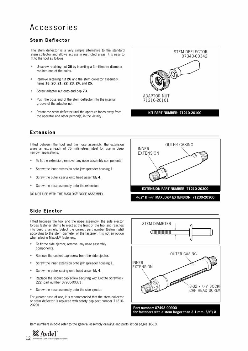
Stem Def lector
Extens ion
S ide E jector
Accessor ies
12
ADAPTOR NUT71210-20101
STEM DEFLECTOR07340-00342
The stem deflector is a very simple alternative to the standardstem collector and allows access in restricted areas. It is easy tofit to the tool as follows:
• Unscrew retaining nut 26 by inserting a 3 millimetre diameterrod into one of the holes.
• Remove retaining nut 26 and the stem collector assembly,items 18, 20, 21, 22, 23, 24, and 25.
• Screw adaptor nut onto end cap 73.
• Push the boss end of the stem deflector into the internalgroove of the adaptor nut.
• Rotate the stem deflector until the aperture faces away fromthe operator and other person(s) in the vicinity.
Item numbers in bold refer to the general assembly drawing and parts list on pages 18-19.
INNER EXTENSION
OUTER CASING
KIT PART NUMBER: 71210-20100
EXTENSION PART NUMBER: 71210-20300
INNER EXTENSION
OUTER CASING
8-32 x 1/4" SOCKECAP HEAD SCREW
Part number: 07498-00900for fasteners with a stem larger than 3.1 mm (1/8") Ø
STEM DIAMETER
Fitted between the tool and the nose assembly, the extensiongives an extra reach of 76 millimetres, ideal for use in deepnarrow applications.
• To fit the extension, remove any nose assembly components.
• Screw the inner extension onto jaw spreader housing 1.
• Screw the outer casing onto head assembly 4.
• Screw the nose assembly onto the extension.
DO NOT USE WITH THE MAXLOK® NOSE ASSEMBLY.
Fitted between the tool and the nose assembly, the side ejectorforces fastener stems to eject at the front of the tool and reachesinto deep channels. Select the correct part number (below right)according to the stem diameter of the fastener. It is not an optionwhen placing Maxlok® fasteners.
• To fit the side ejector, remove any nose assemblycomponents.
• Remove the socket cap screw from the side ejector.
• Screw the inner extension onto jaw spreader housing 1.
• Screw the outer casing onto head assembly 4.
• Replace the socket cap screw securing with Loctite Screwlock222, part number 07900-00371.
• Screw the nose assembly onto the side ejector.
For greater ease of use, it is recommended that the stem collectoror stem deflector is replaced with safety cap part number 71210-20201.
3/16" & 1/4" MAXLOK® EXTENSION: 71230-20300

13
Serv ic ing the Too l
I M P O R T A N TRead Safety Instructions on page 4.
The employer is responsible for ensuring that tool maintenance instructions are given to the appropriatepersonnel.
The operator should not be involved in maintenance or repair of the tool unless properly trained.The tool shall be examined regularly for damage and malfunction.
• Daily, before use or when first putting the tool into service, pour a few drops of clean, light lubricating oil into the air inlet of thetool if no lubricator is fitted on air supply. If the tool is in continuous use, the air hose should be disconnected from the main airsupply and the tool lubricated every two to three hours.
• Check for air leaks. If damaged, hoses and couplings should be replaced.• If there is no filter on the pressure regulator, bleed the air line to clear it of accumulated dirt or water before connecting the air
hose to the tool. If there is a filter, drain it.• Check that the nose assembly is correct for the fastener to be placed.• Check that the stroke of the tool meets the minimum specification (page 5). The last step of the Priming Procedure on page 21
explains how to measure the stroke.• Either a stem collector or a stem deflector must be fitted to the tool if the vacuum extraction is ‘ON’. If it is turned ‘OFF’ a safety
cap must be fitted. See ‘side ejector’ opposite.• Check that base cover 40 is fully tightened onto body 38.• Ensure that rotary valve 65 is correctly adjusted for fastener retention or turned off for Avtainer® and Maxlok® (see ‘Operating
Procedure’ page 7).
• Dismantle and clean nose assembly, with special attention to the jaws. Lubricate with Moly Lithium grease EP 3753 beforeassembling.
• Check for air leaks.
Grease can be ordered as a single item, the part number is shown in the service kit page 15.
First Aid
SKIN:
As the grease is completely water resistant it is best removed with an approved emulsifying skin cleaner.
INGESTION:
Ensure the individual drinks 30ml Milk of Magnesia, preferably in a cup of milk.
EYES:
Irritant but not harmful. Irrigate with water and seek medical attention.
Fire
FLASH POINT: Above 220°C.
Not classified as flammable.
Suitable extinguishing media: CO2, Halon or water spray if applied by an experienced operator.
Environment
Scrape up for burning or disposal on approved site.
Handling
Use barrier cream or oil resistant gloves
Storage
Away from heat and oxidising agent.
Item numbers in bold refer to the general assembly drawing and parts list on pages 18-19.
Dai ly
Weekly
Moly L i th ium Grease EP 3753 Safety Data
• Check and replace Plastic Body and Base Cover if there is evidence of impact damage, chipping or cracks.
Month ly

Molykote 55m Grease Safety Data
Serv ic ing the Too l
14
First Aid
SKIN:
Flush with water. Wipe off.
INGESTION:
No first aid should be needed.
EYES:
Flush with water.
Fire
FLASH POINT: Above 101.1°C. (closed cup)
Explosive Properties: No
Suitable Extinguishing Media: Carbon Dioxide Foam, Dry Powder or fine water spray.
Water can be used to cool fire exposed containers.
Environment
Do not allow large quantities to enter drains or surface waters.
Methods for cleaning up: Scrape up and place in suitable container fitted with a lid. The spilled product produces an extremelyslippery surface.
Harmful to aquatic organisms and may cause long-term adverse effects in the aquatic environment. However, due to the physicalform and water - insolubility of the product the bioavailability is negligible.
Handling
General ventilation is recommended. Avoid skin and eye contact.
Storage
Do not store with oxidizing agents. Keep container closed and store away from water or moisture.
First Aid
SKIN:
No first aid should be needed.
INGESTION:
No first aid should be needed.
EYES:
No first aid should be needed.
INHALATION:
No first aid should be needed.
Fire
FLASH POINT: Above 101.1°C. (closed cup)
Explosive Properties: No
Suitable Extinguishing Media: Carbon Dioxide Foam, Dry Powder or fine water spray.
Water can be used to cool fire exposed containers.
Environment
No adverse effects are predicted.
Handling
General ventilation is recommended. Avoid eye contact.
Storage
Do not store with oxidizing agents. Keep container closed and store away from water or moisture.
Molykote 111 Grease Safety Data
Annual ly
Serv ic ing the Too l
15
PART Nº DESCRIPTIONPART Nº DESCRIPTION
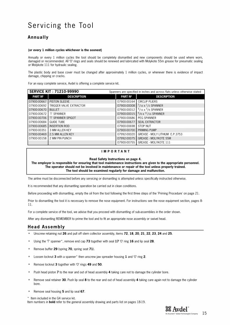
SERVICE KIT : 71210-99990 Spanners are specified in inches and across flats unless otherwise stated
07900-00667 PISTON SLEEVE07900-00692 TRIGGER VALVE EXTRACTOR07900-00670 BULLET07900-00672 'T' SPANNER07900-00706 'T' SPANNER SPIGOT07900-00684 GUIDE TUBE07900-00685 INSERTION ROD07900-00351 3 MM ALLEN KEY07900-00469 2.5 MM ALLEN KEY07900-00158 2 MM PIN PUNCH
07900-00164 CIRCLIP PLIERS07900-00008 7/16 x 1/2 SPANNER07900-00012 9/16 x 5/8 SPANNER07900-00015 5/8 x 11/16 SPANNER07900-00686 PEG SPANNER07900-00677 SEAL EXTRACTOR07900-00698 STOP NUT07900-00700 PRIMING PUMP07992-00020 GREASE - MOLY LITHIUM E.P.375307992-00075 GREASE - MOLYKOTE 55M07900-00755 GREASE - MOLYKOTE 111
(or every 1 million cycles whichever is the soonest)
Annually or every 1 million cycles the tool should be completely dismantled and new components should be used where worn,damaged or recommended. All ‘O’ rings and seals should be renewed and lubricated with Molykote 55m grease for pneumatic sealingor Molykote 111 for hydraulic sealing.
The plastic body and base cover must be changed after approximately 1 million cycles, or whenever there is evidence of impactdamage, chipping or cracks.
For an easy complete service, Avdel is offering a complete service kit.
The airline must be disconnected before any servicing or dismantling is attempted unless specifically instructed otherwise.
It is recommended that any dismantling operation be carried out in clean conditions.
Before proceeding with dismantling, empty the oil from the tool following the first three steps of the 'Priming Procedure' on page 21.
Prior to dismantling the tool it is necessary to remove the nose equipment. For instructions see the nose equipment section, pages 8-11.
For a complete service of the tool, we advise that you proceed with dismantling of sub-assemblies in the order shown.
After any dismantling REMEMBER to prime the tool and to fit an appropriate nose assembly or swivel head.
I M P O R T A N T
Read Safety Instructions on page 4.The employer is responsible for ensuring that tool maintenance instructions are given to the appropriate personnel.
The operator should not be involved in maintenance or repair of the tool unless properly trained.The tool should be examined regularly for damage and malfunction.
* Item included in the G4 service kit.Item numbers in bold refer to the general assembly drawing and parts list on pages 18-19.
• Unscrew retaining nut 26 and pull off stem collector assembly, items 72, 18, 20, 21, 22, 23, 24 and 25.
• Using the ‘T’ spanner*, remove end cap 73 together with seal 17 ‘O’ ring 16 and lip seal 28.
• Remove buffer 29 (spring 70, spring seat 71).
• Loosen locknut 3 with a spanner* then unscrew jaw spreader housing 1 and ‘O’ ring 2.
• Remove locknut 3 together with ‘O’ rings 49 and 50.
• Push head piston 7 to the rear and out of head assembly 4 taking care not to damage the cylinder bore.
• Remove seal retainer 30. Push lip seal 8 to the rear and out of head assembly 4 taking care again not to damage the cylinderbore.
• Remove seal housing 5 and lip seal 67.
Head Assembly

Head Assembly
Pneumat ic P is ton Assembly
Va lve Spoo l Assembly
Tr igger
Serv ic ing the Too l
16
Assemble in reverse order to dismantling noting the following points:
• Place lip seal 8 onto the insertion rod* ensuring correct orientation. Push the guide tube* into the head of the tool and push theinsertion rod* with the seal into place through the guide tube*. Pull the insertion rod* out then the guide tube.
• Drop seal retainer 30 against lip seal 8 large flange first.
• Fit seals 11 and 13 onto the piston.
• Lubricate the cylinder bore and place the piston sleeve* into the back of head assembly 4. Slide the bullet* onto the threaded part ofpiston 7 and push the piston with the seals through the piston sleeve* as far as it will go. Slide the bullet* off the piston and removethe piston sleeve.
• Fit seal housing 5 and lip seal 67.
• Tighten jaw spreader housing 1 fully tightened onto head piston 7 BEFORE tightening locknut 3 against it.
• Use Loctite 932 when reassembling Retaining Nut 26.
• Remove ‘ON/OFF’ valve assembly 60.
• Clamp the body of the inverted tool across the air inlet bosses in a vice fitted with soft jaws.
• Using the peg spanner* unscrew base cover 40, remove ‘O’ ring 75 and pull out cylinder liner 45.
• Remove pneumatic piston assembly 42 from body 38 together with ‘O’ ring 39, lip seal 41 and guide ring 35.
• Engage the seal extractor* into seal assembly 34 and pull it out of the intensifier tube of head assembly 4.
Before assembling in reverse order fill the intensifier tube with oil and insert seal as seal assembly 34 using the extractor. Push downand head piston 7 will move back slightly. Unscrew the extractor.
• Remove pneumatic piston assembly 42 and seal assembly 34 as described immediately above.
• Using the ‘T’ spanner* and ‘T’ spanner spigot* undo clamp nut 36 and remove it together with top plate 63, transfer tubeassembly 44, ‘O’ ring 6, valve rod 43 and silencer pads 62.
• Release the tool from the vice and separate body 38 with ‘O’ ring 31 from handle assembly 32.
• Remove ‘O’ ring 33 from the intensifier tube and pull off head assembly 4 from handle assembly 32.
• Push out valve seat 64 with both ‘O’ rings 6.
• Pull out all the components of valve spool assembly 54.
• Finally remove ‘O’ ring 59 out of the handle counterbore.
Assemble in reverse order noting the following points -• Ensure that the central port in valve seat 64 faces upwards.• Use Loctite 243 when reassembling Clamp Nut 36, torque to 11ft lb (14.91 Nm).
• Using the 2 millimetre diameter pin punch*, drive trigger pin 48 out and lift off trigger 47.
• Unscrew trigger valve 46 using the trigger valve extractor*.
Assemble in reverse order to dismantling.
I M P O R T A N TCheck the tool against daily and weekly servicing
Priming is ALWAYS necessary after the too has been dismantled and prior to operating.
* Item included in the G4 service kit. For complete list see page 15.Item numbers in bold refer to the general assembly drawing and parts list on pages 18-19.

17
Notes

18
Genera l Assembly o f Base Too l 71230-02000
A - A
6263
6
6 69
5958
57
54-5
6
5552
536
60
61
6264
B - B
6665
37 38 4039 75
3133
34
AA 42434445 41
36
35
BB
12
34
910
58
3130 32
464867 47
5150
49
2673
7028
7216
1718
14
2021 22
2524
117
A23
1376
74

19
Par ts L is t for 71230-02000
01 02 03 04 05 06 07 08 09 10 11 13 14 16 17 18 20 21 22 23 24 25 26 28 30 31 32 33 34 35 36 37 38 39
7121
0-02
101
0700
3-00
277
7123
0-02
015
7123
0-03
300
7121
0-02
104
0700
3-00
281
7123
1-02
003
0700
3-00
273
7123
0-02
041
0700
3-00
194
0700
3-00
341
0700
3-00
342
7121
0-02
022
0700
3-00
278
7121
0-02
029
0700
3-00
311
0764
0-00
239
7121
0-02
051
7121
0-02
035
7121
0-02
034
0734
0-00
335
0764
0-00
244
7121
0-02
028
0700
3-00
374
7123
0-02
019
0700
3-00
288
7121
0-04
000
0700
3-00
287
7123
0-03
800
7123
0-03
205
7121
0-02
014
7123
0-02
027
7122
0-02
003
0700
3-00
182
JAW
SPR
EADE
R HO
USIN
G'O
' RIN
GLO
CKNU
THE
AD A
SSEM
BLY
SEAL
HOU
SING
'O' R
ING
HEAD
PIS
TON
LIP
SEAL
SCRE
WBO
NDED
SEA
LLI
P SE
AL'O
' RIN
GSU
SPEN
SION
RIN
G'O
' RIN
GSE
AL'O
' RIN
GST
EM C
OLLE
CTOR
OUT
ER #
STEM
COL
LECT
OR B
ODY
#SI
LENC
ER #
SILE
NCER
CAP
#ST
EM C
OLLE
CTOR
END
CAP
#SI
LENC
ER #
RETA
ININ
G NU
TLI
P SE
ALSE
AL R
ETAI
NER
'O' R
ING
HAND
LE A
SSEM
BLY
'O' R
ING
SEAL
ASS
EMBL
YGU
IDE
RING
CLAM
P NU
TLA
BEL
BODY
'O' R
ING
1 1 1 1 1 3 1 1 1 1 1 2 1 1 1 1 1 1 1 1 1 1 1 1 1 1 1 2 1 1 1 1 1 1 - -
- 1 1 - - 3 - 1 1 2 1 2 1 1 1 1 - - 1 - - 1 - - - - - 2 1 1 - - - 1 - -
40 41 42 43 44 45 46 47 48 49 50 51 52 53 54 55 56 57 58 59 60 61 62 63 64 65 66 67 68 69 70 72 73 74 75 76
7122
0-02
006
0700
3-00
274
7123
0-03
210
7122
0-03
500
7123
0-03
600
7122
0-02
012
0700
5-00
088
7121
0-02
008
7121
0-02
024
0700
3-00
310
0700
3-00
204
7123
0-02
102
0700
3-00
127
0700
5-01
274
7121
0-03
400
0700
3-00
268
7121
0-03
402
7121
0-03
401
0700
3-00
042
0700
3-00
271
7121
0-03
700
0700
8-00
010
7121
0-02
031
7121
0-02
021
7121
0-02
009
7121
0-02
013
0700
3-00
189
0700
3-00
333
0790
0-00
707
0700
7-00
224
0749
0-03
002
7140
3-02
110
7123
1-02
001
7122
1-02
007
0700
3-00
376
0700
7-01
503
BASE
COV
ERLI
P SE
ALPN
EUM
ATIC
PIS
TON
ASSE
MBL
Y (IN
CLUD
ES 4
1/35
/39)
VALV
E RO
D AS
SEM
BLY
TRAN
SFER
TUB
E AS
SEM
BLY
CYLI
NDER
LIN
ERTR
IGGE
R VA
LVE
TRIG
GER
TRIG
GER
PIN
'O' R
ING
'O' R
ING
VACU
UM S
LEEV
E'O
' RIN
GPL
UGVA
LVE
SPOO
L AS
SEM
BLY
(55
to 5
8)•
'O' R
ING
• VA
LVE
SPOO
L•
VALV
E BO
DY•
'O' R
ING
'O' R
ING
ON/O
FF V
ALVE
ASS
EMBL
YFL
EXIB
LE H
OSE
SILE
NCER
CLAM
P PL
ATE
VALV
E SE
ATRO
TARY
VAL
VE'O
' RIN
GLI
P SE
ALTO
OL IN
STRU
CTIO
N M
ANUA
LSP
IROL
PIN
SSP
RING
BOTT
LE A
DAPT
OR A
SSEM
BLY
END
CAP
ASSE
MBL
YRU
BBER
BOO
T'O
' RIN
GBO
OK S
YMBO
L LA
BEL
1 1 1 1 1 1 1 1 1 1 1 1 1 1 1 1 1 1 1 1 1 1 2 1 1 1 2 1 1 2 1 1 1 1 1 1
- 1 - - - - - - - 1 1 1 - - 2 - - 2 1 - - 2 - 1 - 2 - 1 - -
ITEM
PART
Nº
DESC
RIPT
ION
QTY
SPAR
ESIT
EMPA
RT N
ºDE
SCRI
PTIO
NQ
TYSP
ARES
71
23
0-0
20
00
PA
RTS
LIS
T*
The
se a
re m
inim
um r
ecom
men
ded
lev
els
of s
par
es b
ased
on
reg
ular
ser
vici
ng 6-
6-
6.9
-7
-5
-8
#
Thes
e it
ems
are
also
ava
ilabl
e as
a c
ompl
ete
kit.
Par
t N
umbe
r 7
12
10
-20
40
0.

20
Pr im ing
Priming is ALWAYS necessary after the tool has been dismantled and prior to operating. It may also be necessary to restore the fullstroke after considerable use, when the stroke may be reduced and fasteners are not fully placed by one operation of the trigger.
The recommended oil for priming is Hyspin VG32 available in 0.5l (part number 07992-00002) or one gallon containers (part number07992-00006). Please see safety data below.
First AidSKIN:Wash thoroughly with soap and water as soon as possible. Casual contact requires no immediate attention. Short term contactrequires no immediate attention.INGESTION:Seek medical attention immediately. DO NOT induce vomiting.EYES:Irrigate immediately with water for several minutes. Although NOT a primary irritant, minor irritation may occur following contact.
FireFlashpoint 232°C. Not classified as flammable.Suitable extinguishing media: CO2, dry powder, foam or water fog. DO NOT use water jets.
EnvironmentWASTE DISPOSAL: Through authorised contractor to a licensed site. May be incinerated. Used product may be sent for reclamation.SPILLAGE: Prevent entry into drains, sewers and water courses. Soak up with absorbent material.
HandlingWear eye protection, impervious gloves (e.g. of PVC) and a plastic apron. Use in well ventilated area.
StorageNo special precautions.
To enable you to follow the priming procedure opposite, you will need to obtain a priming kit:
PART Nº DESCRIPTIONPRIMING KIT : 07900-00688
07900-00351 3mm ALLEN KEY07900-00224 4mm ALLEN KEY07900-00698 STOP NUT07900-00734 MAXLOK® STOP NUT07900-00700 PRIMING PUMP
Oi l Deta i l s
Hysp in VG 32 Oi l Safety Data
Pr iming K i t

Pr iming Procedure
Pr im ing
21
I M P O R T A N T
DISCONNECT THE TOOL FROM THE AIR SUPPLY OR SWITCH OFF AT VALVE 55. REMOVE NOSE ASSEMBLY OR SWIVEL HEAD COMPONENTS.
All operations should be carried out on a clean bench, with clean hands in a clean area.Ensure that the new oil is perfectly clean and free from air bubbles.
Care MUST be taken at all times, to ensure that no foreign matter enters the tool, or serious damage may result.
• Remove bleed screw 9 and seal 10.
• Connect air supply to tool and switch ON/OFF valve 60 to "ON” position.
• Invert tool over suitable container and actuate trigger. Waste oil will be ejected through the bleed screw hole.
CARE SHALL BE TAKEN TO ENSURE THAT THE BLEED HOLE IS NOT DIRECTED TOWARDS THE OPERATOR OR OTHERPERSONNEL.
• Screw stop nut 07900-00698 onto jaw spreader housing 1.
• Disconnect air supply to tool or switch ON/OFF valve 60 to ‘OFF” position.
• Fill the priming pump with oil.
• Screw priming pump 07900-00700 into the bleed screw hole with seal 10 in place.
• Actuate the priming pump by pressing down and releasing several times until resistance is felt.
• Remove the priming pump and the stop nut.
• Replace bleed screw 9 and seal 10.
• Connect air supply to tool and switch ON/OFF valve 60 to ‘ON” position.
• Check that the stroke of the tool meets the minimum specification of 17 millimetres. To check the stroke, measure the distancebetween the front face of jaw spreader housing 1 and the front face of the head, BEFORE pressing the trigger and when thetrigger is fully actuated. The stroke is the difference between the two measurements. If it does not meet the minimumspecification, repeat the priming procedure.
Item numbers in bold refer to the general assembly drawing and parts list on pages 18-19.

22
Fau l t D iagnos is
Item numbers in bold refer to the general assembly drawing and parts list on pages 18-19.
More than one Air leak Tighten joints or replace componentsoperation of the Insufficient air pressure Adjust air pressure to within specification 5trigger needed to Lack of lubrication Lubricate tool at air inlet point 7 & 13place fastener Worn or broken jaws Fit new jaws 8-11
Low oil level or air in oil Prime tool 20-21Build up of dirt inside the nose assembly Service 11
Tool will not grip Worn or broken jaws Fit new jaws 8-11stem of fastener Build up of dirt inside the nose assembly Service 11
Loose jaw housing or chuck collet Tighten against locking ring 9-11Weak or broken spring in nose assembly Fit new spring 8-11Incorrect component in nose assembly Identify and replace 8-11Rotary valve incorrectly adjusted Read ‘Operating Procedure’ 7
Jaws will not release Build up of dirt inside the nose assembly Service 11broken stem of Jaw housing or chuck collet, nose tip andfastener nose casing not properly seated Tighten nose assembly 9-11
Weak or broken spring in nose assembly Fit new spring 8-11Air or oil leak Tighten joints or replace componentsLow oil level or air present in oil Prime tool 20-21
Cannot feed next Broken stems jammed inside tool Empty stem collector 4 (point 14)fastener Check jaw spreader is correct 8-11
Adjust air pressure to within specification 5Rotary valve incorrectly adjusted Adjust following ‘Operating Procedure’ 7
Slow cycle Lack of lubrication Lubricate tool at air inlet point 7 & 13Low air pressure Adjust air pressure to within the specification 5Build up of dirt inside the nose assembly Service 11
Tool fails to operate No air pressure Connect and adjust to within the specification 5Damaged trigger valve 42 Replace 18-19Loose base cover 35 Tighten 18-19Loose stem collector Tighten retaining nut 22 18-19
continued overleaf
Other symptoms or failures should be reported to your local Avdel authorised distributor or repair centre.
SYMPTOM POSSIBLE CAUSE REMEDY PAGE REFSymptom Poss ib le Cause Remedy Page Ref

23
Fau l t D iagnos is
Fastener fails to break Insufficient air pressure Adjust air pressure to within specification 5Fastener outside tool capability Use more powerful Genesis tool.
Contact AvdelLow oil level or air present in oil Prime tool 20-21Incorrect length of fastener (Maxlok® ONLY) Change to correct length
Tool fails to swage Insufficient air pressure Adjust air pressure to within specification 5collar (Maxlok® ONLY) Worn or damaged anvil Replace 10-11
Low oil level or air present in oil Prime tool 20-21Incorrect length of fastener Change to correct length
Other symptoms or failures should be reported to your local Avdel authorised distributor or repair centre.

24
Notes

25
Notes

26
Notes

Dec lara t ion o f Conformi ty
We, Avdel UK Limited, Watchmead Industrial Estate, Welwyn Garden City, Herts, AL7 1LY
declare under our sole responsibility that the product:
Model G4
Serial No. ................................................
to which this declaration relates is in conformity with the following standards:
EN ISO 12100 - parts 1 & 2
BS EN ISO 8662 - part 6 BS EN ISO 11202
BS EN ISO 3744 BS EN 982
ISO EN 792 part 13 - 2000 BS EN 983
following the provisions of the Machine Directive 89/392/EC
(as amended by Directive 91/368/EC, 93/44/EC as superceded by 98/37/EC and 93/68/EC)
This box contains a power tool which is inconformity with Machines Directive89/392/EC. The ‘Declaration of Conformity’is contained within.
Date of issue
A. Seewraj - Product Engineering Manager - Automation Tools
Manual No. Issue Change Note No.
AC 04/065AD 07/17607900-00707
Avdel®, Avdel® SR, Avex®, Avibulb®, Avinox®, Avseal®, Avtainer®, Bulbex®, Cherrymate®, Hemlock®, Interlock®, MBC®, Maxlok®, Q Rivet™,Stavex®, T-Lok®, TLR®, T Rivet™ are trademarks of Avdel UK Limited.
© A
vde
l U
K L
imit
ed
20
07
www.avdel-global.com
AUSTRALIA
Acument Australia Pty Ltd.
891 Wellington Road
Rowville, Victoria 3178
Tel: +61 3 9765 6400
Fax: +61 3 9765 6445
Email: [email protected]
CANADA
Avdel Canada, a Division of Acument
Canada Limited
87 Disco Road
Rexdale
Ontario M9W 1M3
Tel: +1 416 679 0622
Fax: +1 416 679 0678
Email: [email protected]
CHINA
Acument China Ltd.
RM 1708, 17/F., Nanyang Plaza,
57 Hung To Rd., Kwun Tong
Hong Kong
Tel: +852 2950 0631
Fax: +852 2950 0022
Email: [email protected]
FRANCE
Avdel France S.A.S.
33 bis, rue des Ardennes
BP4
75921 Paris Cedex 19
Tel: +33 (0) 1 4040 8000
Fax: +33 (0) 1 4208 2450
Email: [email protected]
GERMANY
Avdel Deutschland GmbH
Klusriede 24
30851 Langenhagen
Tel: +49 (0) 511 7288 0
Fax: +49 (0) 511 7288 133
Email: [email protected]
ITALY
Avdel Italia S.r.l.
Viale Lombardia 51/53
20047 Brugherio (MI)
Tel: +39 039 289911
Fax: +39 039 2873079
Email: [email protected]
JAPAN
Acument Japan Kabushiki Kaisha
Center Minami SKY,
3-1 Chigasaki-Chuo, Tsuzuki-ku,
Yokohama-city, Kanagawa Prefecture
Japan 224-0032
Tel: +81 45 947 1200
Fax: +81 45 947 1205
Email: [email protected]
SINGAPORE
Acument Asia Pacific (Pte) Ltd.
#05-03/06 Techlink
31 Kaki Bukit Road 3
Singapore, 417818
Tel: +65 6840 7431
Fax: +65 6840 7409
Email: [email protected]
SOUTH KOREA
Acument Korea Ltd.
212-4, Suyang-Ri,
Silchon-Eup, Kwangju-City,
Kyunggi-Do, Korea, 464-874
Tel: +82 31 798 6340
Fax: +82 31 798 6342
Email: [email protected]
SPAIN
Avdel Spain S.A.
C/ Puerto de la Morcuera, 14
Poligono Industrial Prado Overa
Ctra. de Toledo, km 7,8
28919 Leganés (Madrid)
Tel: +34 (0) 91 3416767
Fax: +34 (0) 91 3416740
Email: [email protected]
UNITED KINGDOM
Avdel UK Limited
Pacific House
2 Swiftfields
Watchmead Industrial Estate
Welwyn Garden City
Hertfordshire
AL7 1LY
Tel: +44 (0) 1707 292000
Fax: +44 (0) 1707 292199
Email: [email protected]
USA
Avdel USA LLC
614 NC Highway 200 South
Stanfield,
North Carolina 28163
Tel: +1 704 888-7100
Fax: +1 704 888-0258
Email: [email protected]