Embed Size (px)
Citation preview
Ž .Thin Solid Films 313]314 1998 368]372
In situ measurement of principal refractive indices of thin filmsby two-angle ellipsometry
Ian HodgkinsonU, Judith Hazel, Qi hong Wu
Department of Physics, Uni¨ersity of Otago, PO Box 56, Dunedin, New Zealand
Abstract
We show that the principal refractive indices of a tilted-columnar biaxial film can be determined from ellipsometricmeasurements made simultaneously at two angles in the deposition plane during the growth of the film. The index n ,3perpendicular to the deposition plane, is determined by a standard method using interference modulations in the s-polarizedtransmittance T versus thickness d profile recorded by one ellipsometer. For the computation of n and n , wes 1 2simultaneously log the data for two profiles of phase retardation D versus d. These profiles are subject to substantialinterference modulations, but the smoothed gradients correspond to material values in the absence of interference. Analgebraic solution is developed for n and n . This requires the columnar angle c , which we determine from a scanning1 2electron microscope photograph of a section of the film fractured in the deposition plane. Q 1998 Elsevier Science S.A.
Keywords: Birefringence; Ellipsometry; Thin film
1. Introduction
Several ex situ methods have been described fordetermining the principal refractive indices of tilted
w xcolumnar films 1]3 , but specific data relating refrac-tive indices and deposition angles are sparse. As well,some of the films have an open structure that canabsorb moisture and change the refractive indices
w xafter air admittance 4 . Thus a tilted-columnar film oftitanium oxide requires a protective overcoat of anion-assisted layer of a material such as SiO , making2post-deposition measurement of the three principalindices somewhat difficult. It is our view that pre-air-admission values of refractive indices are required forthe design of birefringent coatings, because the biax-ial films must be either intrinsically stable or over-coated.
U Corresponding author. Fax: q64 03 4790964; e-mail:[email protected]
In this article, we describe a method for the in situmeasurement of principal indices. This new method isbased on simultaneous ellipsometry at two angles, andutilizes the gradient of a smoothed retardation versusthickness plot as a means of eliminating the effects ofinterference. The columnar angle is determined after
Ždeposition from an SEM scanning electron micros-.copy micrograph of an edge of the fractured film. As
an example to illustrate the method we determine theprincipal refractive indices of a titanium oxide filmdeposited by electron beam evaporation on to a glasssubstrate at a deposition angle of 608.
2. Theory
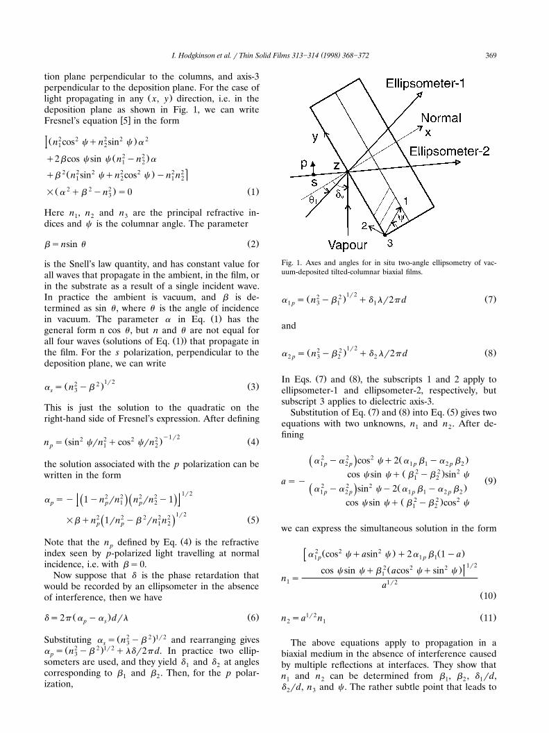
Ž .Fig. 1 illustrates a deposition plane x]y section ofa biaxial film. The material principal axes are labelled1, 2, 3, with axis-1 parallel to the characteristic mi-crostructural columns of the film, axis-2 in the deposi-
0040-6090r98r$19.00 Q 1998 Elsevier Science S.A. All rights reservedŽ .P I I S 0 0 4 0 - 6 0 9 0 9 7 0 0 8 4 8 - 1
( )I. Hodgkinson et al. r Thin Solid Films 313]314 1998 368]372 369
tion plane perpendicular to the columns, and axis-3perpendicular to the deposition plane. For the case of
Ž .light propagating in any x, y direction, i.e. in thedeposition plane as shown in Fig. 1, we can write
w xFresnel’s equation 5 in the form
2 2 2 2 2Ž .n cos cqn sin c a1 2
Ž 2 2 .q2bcos c sin c n yn a1 2
2 2 2 2 2 2 2Ž .qb n sin cqn cos c yn n1 2 1 2
Ž 2 2 2 . Ž .= a qb yn s0 13
Here n , n and n are the principal refractive in-1 2 3dices and c is the columnar angle. The parameter
Ž .bsnsin u 2
is the Snell’s law quantity, and has constant value forall waves that propagate in the ambient, in the film, orin the substrate as a result of a single incident wave.In practice the ambient is vacuum, and b is de-termined as sin u , where u is the angle of incidence
Ž .in vacuum. The parameter a in Eq. 1 has thegeneral form n cos u , but n and u are not equal for
Ž Ž ..all four waves solutions of Eq. 1 that propagate inthe film. For the s polarization, perpendicular to thedeposition plane, we can write
1r22 2Ž . Ž .a s n yb 3s 3
This is just the solution to the quadratic on theright-hand side of Fresnel’s expression. After defining
y1r22 2 2 2Ž . Ž .n s sin crn qcos crn 4p 1 2
the solution associated with the p polarization can bewritten in the form
1r22 2 2 2a sy 1yn rn n rn y1Ž . Ž .p p 1 p 2
1r22 2 2 2 2 Ž .=bqn 1rn yb rn n 5Ž .p p 1 2
Ž .Note that the n defined by Eq. 4 is the refractivepindex seen by p-polarized light travelling at normalincidence, i.e. with bs0.
Now suppose that d is the phase retardation thatwould be recorded by an ellipsometer in the absenceof interference, then we have
Ž . Ž .ds2p a ya drl 6p s
Ž 2 2 .1r2Substituting a s n yb and rearranging givess 3Ž 2 2 .1r2a s n yb qldr2p d. In practice two ellip-p 3
someters are used, and they yield d and d at angles1 2corresponding to b and b . Then, for the p polar-1 2ization,
Fig. 1. Axes and angles for in situ two-angle ellipsometry of vac-uum-deposited tilted-columnar biaxial films.
1r22 2Ž . Ž .a s n yb qd lr2p d 71 p 3 1 1
and
1r22 2Ž . Ž .a s n yb qd lr2p d 82 p 3 2 2
Ž . Ž .In Eqs. 7 and 8 , the subscripts 1 and 2 apply toellipsometer-1 and ellipsometer-2, respectively, butsubscript 3 applies to dielectric axis-3.
Ž . Ž . Ž .Substitution of Eq. 7 and 8 into Eq. 5 gives twoequations with two unknowns, n and n . After de-1 2fining
2 2 2 Ž .a ya cos cq2 a b ya bŽ .1 p 2 p 1 p 1 2 p 22 2 2Ž .cos c sin cq b yb sin c1 2 Ž .asy 9
2 2 2 Ž .a ya sin cy2 a b ya bŽ .1 p 2 p 1 p 1 2 p 22 2 2Ž .cos c sin cq b yb cos c1 2
we can express the simultaneous solution in the form
2 2 2Ž . Ž .a cos cqasin c q2a b 1ya1 p 1 p 11r22 2 2Ž .cos c sin cqb acos cqsin c1n s1 1r2a
Ž .10
1r2 Ž .n sa n 112 1
The above equations apply to propagation in abiaxial medium in the absence of interference causedby multiple reflections at interfaces. They show thatn and n can be determined from b , b , d rd,1 2 1 2 1d rd, n and c . The rather subtle point that leads to2 3
( )I. Hodgkinson et al. r Thin Solid Films 313]314 1998 368]372370
a practical technique for realization of the principalindices is that drd for propagation without interfer-ence can be determined as the gradient of a smoothedD versus d ellipsometric curve. In a previous article
w xon ellipsometry at perpendicular incidence 6 , thegradient was shown to be a robust parameter, evenwhen the principal indices are subject to differentialabsorption and differential inhomogeneity.
Finally, before we conclude this section, we notethat the column angle can be determined, togetherwith the principal refractive indices but at the ex-pense of greater technological complexity, if simulta-neous ellipsometric measurements are made at threeangles. In terms of the relevant a s for the p polariza-tion and the b s,
2 2 Ž 2 2 .a ya b ybŽ .1 p 3 p 2 32 2 2 2Ž .y a ya b ybŽ .2 p 3 p 1 3
tan 2cs2 2 2 2 Ž .a ya qb yb a b ya bŽ .1 p 3 p 1 3 2 p 2 3 p 3
2 2 2 2y a ya qb ybŽ .2 p 3 p 2 3
Ž .= a b ya b1 p 1 3 p 3
Ž .12
here the subscripts 1, 2, 3 correspond to the threeellipsometers.
3. Experimental
We begin by summarizing the practical implemen-tation of the equations in the previous section for
determining the principal indices of a biaxial film.During the growth of the film ellipsometric measure-ments are made at b ssin u and b ssin u . The1 1 2 2configuration of the ellipsometers is fixed polarizer at458-sample-rotating quarter-wave plate-fixed analyzeraligned with the direction of the s polarization. Thisarrangement provides both the magnitude and sign ofthe phase retardation and favours the transmittanceT . A plot of T versus mass thickness as recorded bys sa quartz crystal monitor shows maxima and minima,
w xand these are used in a standard way 3 for thedetermination of n .3
The maxima and minima in T also serve to indi-scate optical thicknesses that are multiples of lr4,independent of crystal calibration. They can be usedto calibrate the mass thickness output logged fromthe quartz crystal monitor, or used in the followingway. Suppose that we consider the stage in the deposi-tion when the optical thickness is one wavelength for
Ž 2the angle of incidence represented by b , then n y1 32 .1r2 Ž . Ž .b dsl and hence lrd in Eqs. 7 and 8 can be1
Ž 2 2 .1r2replaced by n yb . Next the phase retardations3 1d and d , corresponding to the optical thickness of l1 2
Žand appropriate to forward propagation without in-.terference , are determined from smoothed d versus
mass thickness plots. Either way we now have suffi-cient data for the computation of a and a .1 2
Ž . Ž .Eqs. 9 and 10 require the column angle c .Several possibilities exist for measuring or estimatingc . As noted in the previous section, c could bedetermined in situ by three-angle ellipsometry. An-other possibility is computation using the tangent rule
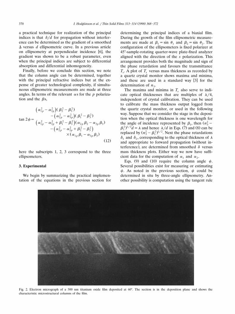
Fig. 2. Electron micrograph of a 500 nm titanium oxide film deposited at 608. The section is in the deposition plane and shows thecharacteristic microstructural columns of the film.
( )I. Hodgkinson et al. r Thin Solid Films 313]314 1998 368]372 371
w x7 which has been shown to be appropriate for a widew xrange of films 8 . However, we have noted examples
w xin which the rule is unreliable for biaxial films 9 .Currently we prefer and use post-deposition SEMexamination of an edge of the film fractured in thedeposition plane for positive identification of colum-nar structure and determination of c . The hot-wire
w xmethod 10 is used to produce a clean fracture of thesubstrate]film structure in the deposition plane of thefilm.
4. Example and discussion
Fig. 2 shows a section of a titanium oxide filmdeposited at a vapour angle of 608, at a depositionrate of 0.28 nmrs, substrate temperature 3008C, andin a residual atmosphere of oxygen at pressure 2=10y4 mbar. Close examination of the photographreveals that some columns are incomplete or broken,possibly adding to the uncertainty in a measurementof c . In this particular example, the columnar angle is
Ž .estimated to be 32"1 8, significantly less than they1 Ž .value of tan 0.5 tan 608 s418 predicted by the
tangent rule.The ellipsometric angles of incidence were u sy581
and u sy358. From the T versus thickness curve2 sthat was recorded at angle u , the value of n was1 3calculated as 1.950"0.010.
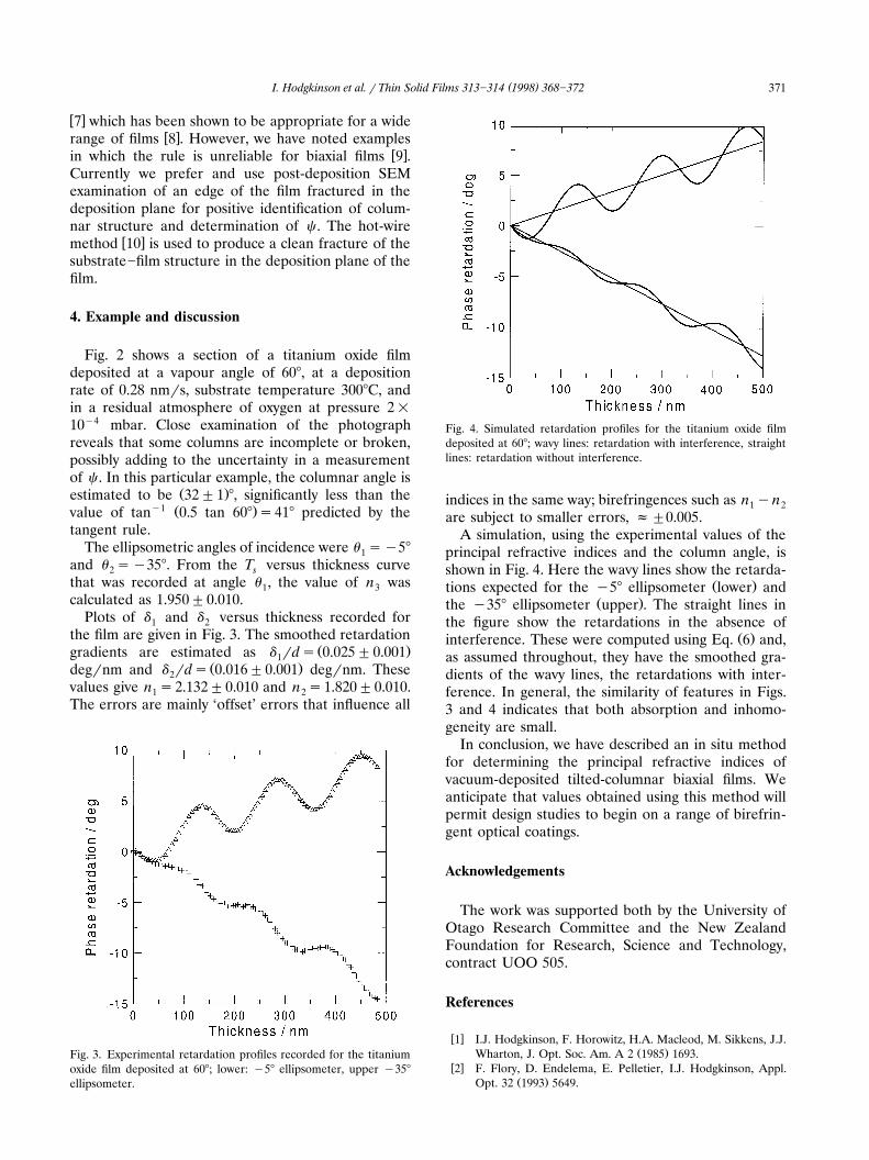
Plots of d and d versus thickness recorded for1 2the film are given in Fig. 3. The smoothed retardation
Ž .gradients are estimated as d rds 0.025"0.0011Ž .degrnm and d rds 0.016"0.001 degrnm. These2
values give n s2.132"0.010 and n s1.820"0.010.1 2The errors are mainly ‘offset’ errors that influence all
Fig. 3. Experimental retardation profiles recorded for the titaniumoxide film deposited at 608; lower: y58 ellipsometer, upper y358
ellipsometer.
Fig. 4. Simulated retardation profiles for the titanium oxide filmdeposited at 608; wavy lines: retardation with interference, straightlines: retardation without interference.
indices in the same way; birefringences such as n yn1 2are subject to smaller errors, f"0.005.
A simulation, using the experimental values of theprincipal refractive indices and the column angle, isshown in Fig. 4. Here the wavy lines show the retarda-
Ž .tions expected for the y58 ellipsometer lower andŽ .the y358 ellipsometer upper . The straight lines in
the figure show the retardations in the absence ofŽ .interference. These were computed using Eq. 6 and,
as assumed throughout, they have the smoothed gra-dients of the wavy lines, the retardations with inter-ference. In general, the similarity of features in Figs.3 and 4 indicates that both absorption and inhomo-geneity are small.
In conclusion, we have described an in situ methodfor determining the principal refractive indices ofvacuum-deposited tilted-columnar biaxial films. Weanticipate that values obtained using this method willpermit design studies to begin on a range of birefrin-gent optical coatings.
Acknowledgements
The work was supported both by the University ofOtago Research Committee and the New ZealandFoundation for Research, Science and Technology,contract UOO 505.
References
w x1 I.J. Hodgkinson, F. Horowitz, H.A. Macleod, M. Sikkens, J.J.Ž .Wharton, J. Opt. Soc. Am. A 2 1985 1693.
w x2 F. Flory, D. Endelema, E. Pelletier, I.J. Hodgkinson, Appl.Ž .Opt. 32 1993 5649.
( )I. Hodgkinson et al. r Thin Solid Films 313]314 1998 368]372372
w x Ž .3 F. Horowitz, S.B. Mendes, Appl. Opt. 33 1994 2659.w x4 I.J. Hodgkinson, F. Horowitz, H.A. Macleod, M. Sikkens, J.J.
Ž .Wharton, Appl. Opt. 24 1985 1568.w x5 M. Born, E. Wolf, Principles of Optics, Pergamon Press,
London, 1959.w x Ž .6 Q.H. Wu, I.J. Hodgkinson, J. Opt. 25 1994 43.w x7 J.M. Nieuwenhuizen, H.B. Haanstra, Philips Tech. Rev. 27
Ž .1966 87.w x8 H.J. Leamy, G.H. Gilmer, A.G. Dirks, The microstucture of
Ž .vapor deposited thin films, in: E. Kaldis Ed. , Current Topicsin Materials Science, vol. 6, North-Holland, Amsterdam, 1980,p. 309.
w x9 I.J. Hodgkinson, S.J. Cloughley, Q.H. Wu, S. Kassam, Appl.Ž .Opt. 35 1996 5563.
w x10 T. Muller, H.K. Pulker, Thin film morphology in TEM as¨revealed by heat-shock fracturing and replication of film cross
Ž .sections, in: F. Abeles Ed. , Optical Interference Coatings,`Proc. Soc. Photo-Opt. Instrum. Eng. 2253, 1994, p. 584.