Embed Size (px)
Citation preview

Article
In-situ Observation of Martensite Decomposition in
HAZ of Cr-Mo Steel Weldment Isaratat Phung-on1,a,* , Sudarat Khetsoongnoen2,b, Jongkol Srithorn2,c,
Chanan Euaruksakul3,d, and Pat Photongkam3,e
1 Maintenance Technology Center, King Mongkut’s University of Technology Thonburi, Bangkok 10140, Thailand 2 Industrial Engineering, Institute of Engineering, Suranaree University of Technology, Nakhon Ratchasima 30000, Thailand 3 Synchrotron Light Research Institute (Public Organization), Nakhon Ratchasima 30000, Thailand E-mail: [email protected] (Corresponding author), [email protected], [email protected], [email protected], [email protected] Abstract. In-situ observation of martensite decomposition at Heat Affected Zone (HAZ) was investigated on a dissimilar joining between 2.25Cr-0.5Mo grade T22 as base material and ER90S-B9 as filler metal using GTAW process using LEEM at a synchrotron facility. A post weld heat treatment (PWHT) cycle was simulated on a welded specimen in high vacuum chamber by heating cartridge and electron bombardment. Both effects PWHT duration and weld areas were studied for comparisons. At the simulated PWHT between 690°C -700°C in CGHAZ, martensite started to decompose by the dissolution of carbide flakes. The prior-austenite grain boundaries were also shown during the process. The same phenomena were also observed in FGHAZ with different extent. In un-affected base material, ferrite and new pearlite grains presented and grew at the expense of old pearlite. Longer PWHT duration resulted in more ferrite formed in all weld areas. Raising PWHT temperature to 730°C could push the reaction above Eutectoid temperature as the new austenite formed at grain boundaries. The proposed mechanism for martensite decomposition would be in steps as dissolution of carbide followed by formation of ferrite and growth as PWHT proceeded. Keywords: PWTH, heat-affected zone (HAZ), martensite decomposition, LEEM, in-situ observation.
ENGINEERING JOURNAL Volume 23 Issue 5
Received 5 January 2019
Accepted 11 June 2019
Published 30 September 2019
Online at http://www.engj.org/
DOI:10.4186/ej.2019.23.5.59

DOI:10.4186/ej.2019.23.5.59
60 ENGINEERING JOURNAL Volume 23 Issue 5, ISSN 0125-8281 (http://www.engj.org/)
1. Introduction In steam turbine power generation, Cr-Mo steels have been selected owning to their elevated temperate strength and creep resistance [1-5]. Several grades have been used such as 2.25 Cr-1Mo (grade T22) for general application, and 9Cr-1Mo (grade T91) for higher operating temperature. In steam piping assemblies or equipment, there are process steps working at different temperatures such as economizer, heater, and super heater which require dissimilar joint among materials both during fabrication and repair. This could cause a concern during welding and post weld heat treatment (PWHT) in which soft zone and hard zone could occur at the weld interface in Heat Affected Zone (HAZ) and weld metal, respectively. Many researchers studied microstructures of the soft zone [4-12] as well as performed mechanical characterization in dissimilar metal weldments [4, 8-16]. In as-welded condition, martensite structure was found in heat-affected zone (HAZ). However, the martensite was changed to ferrite after PWHT, forming a soft zone. It has been proposed that this behavior is due to the carbon migration during PWHT [6-8, 13, 17-20] as the result of the affinity of Cr.
It has been believed that the formation of soft zone in the HAZ could cause the failure during in service of the material especially in creep mode. This was shown in the study of creep life assessment of Cr-Mo material by Petchsang et. al. [21] as the failure occurred close to the HAZ. Another investigation related the changes in local structures showed the decomposition of martensite after extend period in PWHT [22].
With many investigations stated above, those were performed in ex-situ investigation. There was still no in-situ investigation which could help provide information, in term of mechanism, for decomposition of martensite into ferrite in the HAZ of dissimilar welding between high and low Cr contents. This study shows sequences on microscopic transformations of the martensite to ferrite in real-time using Low Energy Electron Microscope (LEEM). A specimen from T22 welded with ER90S-B9 was heated under the simulated PWHT condition and the microstructures were observed at various times and locations.
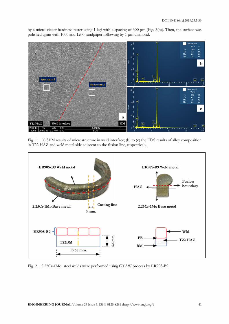
2. Methods 2.1. Materials and Welding Process The material used as base metal was 2.25Cr-1Mo steel tube (T22) with dimensions 65 mm (O.D.) × 6.5 mm (thickness). The nominal and measured compositions of the base metal and the deposited Weld Metal (WM) are listed as shown in Table 1 and Fig. 1 by using the Scanning Electron Microscopy (SEM) and an Energy-Dispersive Spectroscopy (EDS) was performed in order to determine the alloying composition. The specimen was prepared using Gas Tungsten Arc Welding (GTAW) process with the ER90S-B9 filler metal. An overlay joint was selected to deposit the weld metal on the wall thickness of the tube as shown in Fig.1. Welding parameters implemented were 60 A with 11-12V using DCEN polarity. Table 1. Chemical composition of the material and welding wire used
Material Composition Element (wt-%)
Cr Mo Mn Fe
2.25Cr-1Mo
base metal
nominal(1) 1.90-2.60 0.87-1.13 0.30-0.60 95.1-96.8
measured(3) 2.4 1 0.6 96.0
ER90S-B9
weld metal
nominal(2) 8.00-9.50 0.80-1.10 1.25 87.3-90.3
measured(3) 4.1 1.1 0.4 94.3
Note: (1) referring to [23]; (2) referring to [24]; (3) measured in by SEM/EDS analysis. The welded tube was cut in longitudinal direction to reveal the cross section of deposited weld metal
in the size about 5 mm long and 3 mm wide (Fig. 2). Conventional preparation for microstructural examination was then performed by sandpaper No. 100, 320, 400, 600, 800, 1000 and 1200 successively. In this case, the specimen must be grinded to the thickness less than 1 mm (Fig. 3(a)) to reduce the heat mass in order to minimize the chance of outgassing and spontaneous arc during LEEM operation. To reveal its microstructure in as-welded condition and locate the weld interface prior observation, the specimen was etched using 10 ml HNO3 + 20ml HCl + 30ml water for 60 seconds. The weld interface was then marked
DOI:10.4186/ej.2019.23.5.59
ENGINEERING JOURNAL Volume 23 Issue 5, ISSN 0125-8281 (http://www.engj.org/) 61
by a micro-vicker hardness tester using 1 kgf with a spacing of 300 μm (Fig. 3(b)). Then, the surface was polished again with 1000 and 1200 sandpaper following by 1 μm diamond.
Fig. 1. (a) SEM results of microstructure in weld interface; (b) to (c) the EDS results of alloy composition in T22 HAZ and weld metal side adjacent to the fusion line, respectively.
Fig. 2. 2.25Cr-1Mo steel welds were performed using GTAW process by ER90S-B9.
a
b
c
DOI:10.4186/ej.2019.23.5.59
62 ENGINEERING JOURNAL Volume 23 Issue 5, ISSN 0125-8281 (http://www.engj.org/)
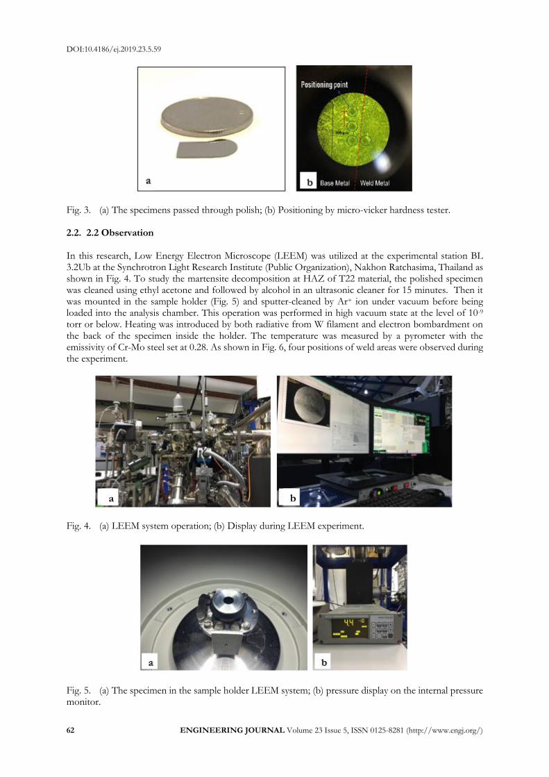
Fig. 3. (a) The specimens passed through polish; (b) Positioning by micro-vicker hardness tester. 2.2. 2.2 Observation In this research, Low Energy Electron Microscope (LEEM) was utilized at the experimental station BL 3.2Ub at the Synchrotron Light Research Institute (Public Organization), Nakhon Ratchasima, Thailand as shown in Fig. 4. To study the martensite decomposition at HAZ of T22 material, the polished specimen was cleaned using ethyl acetone and followed by alcohol in an ultrasonic cleaner for 15 minutes. Then it was mounted in the sample holder (Fig. 5) and sputter-cleaned by Ar+ ion under vacuum before being loaded into the analysis chamber. This operation was performed in high vacuum state at the level of 10-9 torr or below. Heating was introduced by both radiative from W filament and electron bombardment on the back of the specimen inside the holder. The temperature was measured by a pyrometer with the emissivity of Cr-Mo steel set at 0.28. As shown in Fig. 6, four positions of weld areas were observed during the experiment.
Fig. 4. (a) LEEM system operation; (b) Display during LEEM experiment.
Fig. 5. (a) The specimen in the sample holder LEEM system; (b) pressure display on the internal pressure monitor.
b a

DOI:10.4186/ej.2019.23.5.59
ENGINEERING JOURNAL Volume 23 Issue 5, ISSN 0125-8281 (http://www.engj.org/) 63
Fig. 6. Position of the weldment in each area: 1. Position 1: Coarse-grained heat affected zone (CGHAZ). 2. Position 2: Fine-grained heat affected zone (FGHAZ) 250 micron away from the fusion line. 3. Position 3: T22 Base metal (BM) 500 micron away from the fusion line. 4. Position 4: Heat affect zone in weld metal side adjacent to the fusion line
Figure 7 showed the heating history during the experiment. In order to simulate the condition of
PWHT, the specimen was heated from room temperature to below the Eutectoid temperature (A1) at 690°C as recommended by ASME BPVC as minimum of 675°C for T22 (P-No. 5A Group No.1) and 705°C for ER90-B9 which could be comparable to T91 (9Cr 1Mo). However, since the PWHT temperature was determined by base material which T91 was not used in this case, therefore, the only material concerned would be T22 which required 675°C. In addition, using PWHT temperature of ER90S-B9 would be too high for T22 as it might be above the eutectoid point which material would become austenite and subsequence martensite.
The temperature was held between 690°C - 700°C for 14 hrs. under LEEM to observe effect of PWHT duration on microstructure. All 4 areas were observed from time to time for comparisons on PWHT effects on each weld area. Finally, the temperature was raised to 730°C which was above the Eutectoid. This was to determine the change of microstructure into the 2 phase-region or the starting of the decomposition of ferrite to form austenite.
Fig. 7. Simulated PWHT history.

DOI:10.4186/ej.2019.23.5.59
64 ENGINEERING JOURNAL Volume 23 Issue 5, ISSN 0125-8281 (http://www.engj.org/)
3. Results and Discussion In this research, the effect of duration (time of PWHT) and distance from the fusion boundary (weld areas) were observed. Starting at room temperature, the microstructure of 2.25Cr-1Mo base material (position 3) consisted of ferrite, pearlite and carbide precipitate both within grain and along the grain boundaries [4]. Upon welding with GTAW using ER90S-B9 filler metal, the heating from welding on the specimen created different welding areas due to different in thermal history from various peak temperatures depending on distance from fusion boundary. This resulted the gradient of microstructures.
In CGHAZ (position 1), there was martensite structure resulted from fast cooling of prior-austenite in which the peak temperature was above the critical temperature. On the other hands, in FGHAZ (position 2), the peak temperature was between 2 phases among austenite and ferrite. This resulted in ferrite and martensite mix from transformed prior-austenite. The near fusion boundary weld metal (position 4) as a mixture between ER90S-B9 and melted base material was melted and re-solidified as martensite structure with columnar morphology. Since this area possibly was not mixed completely in macroscopic scale, the chemical composition especially for Cr would be high compared to CGHAZ.
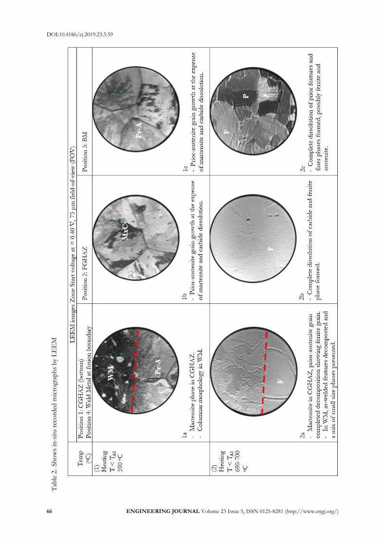
The in-situ recorded micrographs by LEEM were shown in Table 2. For easy understanding changes shown the following abbreviations were used.
WM : Weld Metal Pr-A : Prior Austenite MxCy : Carbides both from precipitations and formed inside martensite F : Ferrite P : Pearlite A : Austenite As the simulated PWHT cycle began, prior-austenite grain boundaries started to present in CGHAZ at
temperature about 650°C as shown in Table 2:1a-bottom. In the same way in Table 2:1b and 1c, both in FGHAZ and BM showed the prior-austenite grain boundaries. This areas martensite and its mixtures (ferrite + martensite) due to fast cooling from austenite phase upon welding. The base material was possibly martensite mixture as well due to its chemical composition. This also occurred in weld metal (Table 2:1a – top) with finer features and carbides.
When the temperature rose to between 690°C - 700°C, prior-austenite grain boundaries were even more pronounced as shown Table 2:2a-bottom. This phenomenon was similar to what it’s called “Tinned Etching” in which the prior features could be shown upon heating. Carbide flakes in martensite started to dissolve showing clearer prior-austenite grain. The ferrite grain started to be more pronounce as the prior-austenite grain boundaries started to bend slightly. On the other hand, in FGHAZ, all features of microstructures were gone, while in BM there started to present the formation of ferrite and pearlite as more equilibrium phase condition achieved. The features in weld metal (Table 2:2a-top) was also more pronounced with a mix of small size phases and microstructures. The columnar morphology started to become rounded as inhering the effect of solidification direction from welding.
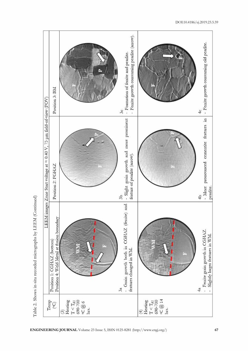
After holding at the temperature between 690°C - 700°C for 6 hours, there were little changes in
CGHAZ as it reached the completion of martensite decomposition in which no more carbide flakes to be
dissolved. The grain size started to grow bigger as the pinning effects had gone from decomposition of
martensite (Table 2:3a). This was also due to the higher driving force to become larger prior-austenite grains
together with residual stress from welding in this area. As a result, the soft zone with lower hardness was
formed in this location corresponding to S. Petsang [8, 21, 22] and C. Sudha et al. [14]. In FGHAZ (Table
2:3b), ferrite grain boundary was somewhat shaper as well as feature of pearlite was more prominent. At
this temperature, the equilibrium phase for the T22 material was more ferrite and a few pearlite. In the same
way, in weld metal, microstructure features started to grow consuming each other. On the other hand, in
base material the ferrite grains began to grow noticeably consuming some pearlite and grain boundaries
became more prominent as shown in Table 2:3c.
After further holding at the PWHT temperature to 14 hours, ferrite grain boundaries in CGHAZ continued to grow as shown in Table 2:4a. This was also occurred in weld metal in which the microstructure features continued to grow. The observation might contradict to the previous literatures which reported that the carbides should form and become the hard zone. However, in this case, the temperature used for simulating the PWHT temperature was about 700°C which was higher than recommend for T22 material or P-No. 5A Group No. 1 (according to ASME BPVC) at 675°C. Since the temperature was well beyond
DOI:10.4186/ej.2019.23.5.59
ENGINEERING JOURNAL Volume 23 Issue 5, ISSN 0125-8281 (http://www.engj.org/) 65
the recommendation which was close to the Eutectoid point, carbides were more prone to dissolution than precipitation. Therefore, its microstructures were complete matrix features with un-noticeable precipitates. However, another possibility, the carbides might form during cooling that could be observed in ex-situ observation which was not the case for this experiment. In FGHAZ, the pearlite was even more pronounced. As can be seen from Table 2:4b, the laminar pattern of pearlite showed with sharper grain boundaries. For BM, carbides in pearlite were also dissolved and new ferrite and pearlite formed consuming the prior features to reach the equilibrium stage between ferrite and pearlite conforming to the chemical composition of the material.
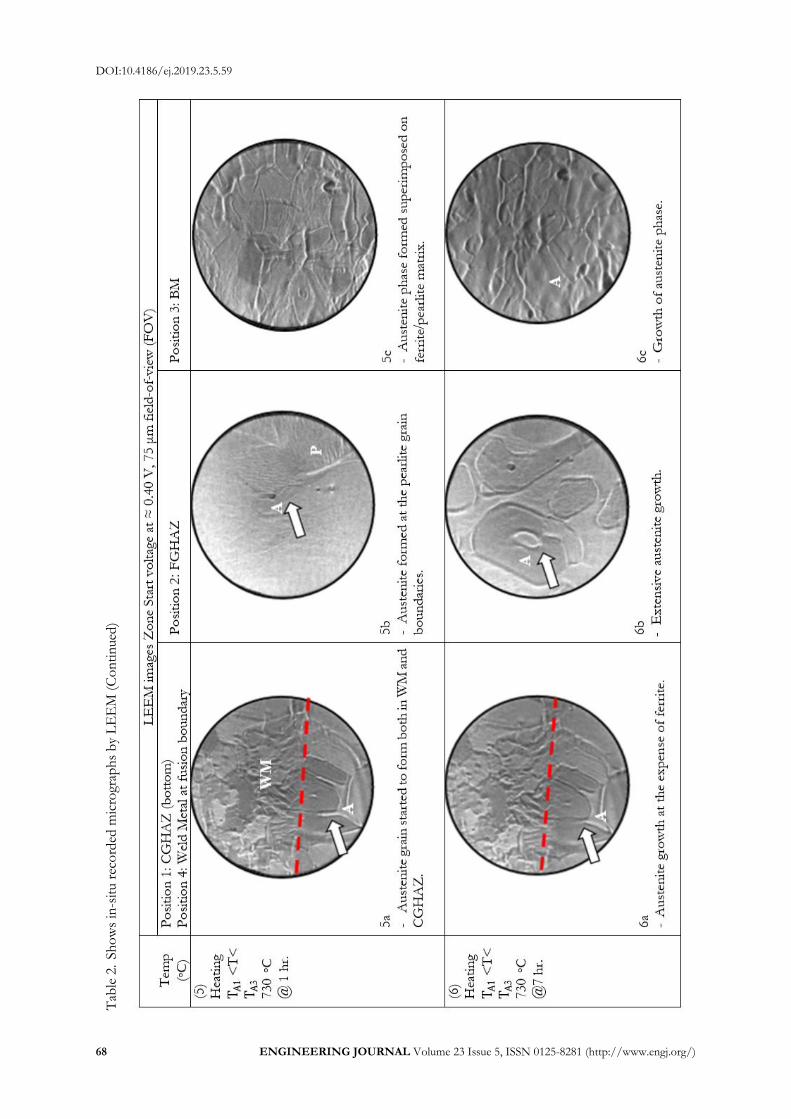
Next, the specimen was heated to 730°C in order to ensure that the simulated PWHT temperature was not beyond Eutectoid temperature, that could compromise the observation results, as well as to continue the observation of phase transformation at the 2-phase region of Fe-C phase diagram in which both ferrite and austenite should present together.
After holding the temperature at 730°C for 1 hours, the austenite phase started to form in both CGHAZ and weld metal splitting ferrite grains (at the triple point junctions) as shown in Table 2:5a-top and bottom. In the same way, both FGHAZ and BM experienced the formation of austenite phase starting at the triple point junctions of grain boundaries. Both of existing ferrite and pearlite, accordingly, were consumed by newly formed austenite/ferrite mixed microstructures. After further holding the temperature at 730°C to 7 hours, austenite grains were larger in all locations as shown in Table 2:6a-6c. This indicated that the temperature was well beyond the Eutectoid point at the 2-phase region. This information could also be applied to infer that the too high PWHT temperature could result in an adverse effect on the properties of the weldments in all weld areas, as the newly formed austenite could transform into martensite from being rapidly cooled to room temperature after completion of the PWHT procedure. It needs to be aware not to exceed the Eutectoid temperature as most codes and standards always indicate the minimum PWHT temperature but not recommend the maximum PWHT temperature boundary. From the information above, the decomposition mechanism of martensite in weld areas especially in CGHAZ could be suggested. Upon, heating as PWHT progress, carbides in martensite started to dissolve into the matrix. This resulted in instability of martensite which then transformed to become ferrite. The dissolution of carbides could also free the grain boundaries to move as grain growth processed. Depending on the thermal history of each weld area, ferrite formed could grow and consume prior microstructure features both in the as-received in BM and as-welded in heat affected zone. In addition, the results were also consistent to other studies that the longer the PWHT duration and the higher the temperature of PWHT were, the larger the grain size was [14, 25]. Nevertheless, S. K. Albert et al. [6] also indicated that the width of microstructure features was affected by PWHT duration which corresponded to the results of observations.
4. Conclusion The in-situ observation by LEEM of martensite decomposition in soft zone or CGHAZ of Cr-Mo steel grade T22 welded by ER90S-B9 could be concluded as follows:
1. Martensite decomposition started by dissolution of carbides in martensite flakes, followed by formation of ferrite phase in the CGHAZ.
2. After complete decomposition of the martensite, ferrite phase expanded and grew to form the soft zone.
3. FGHAZ also experienced the same situation as in CGHAZ but at different extent while the un-affected BM behaved differently as the ferrite grew, consuming the pearlite.
4. Longer PWHT duration resulted in larger grain size in all weld areas. 5. Too high PWHT temperature could result in formation of new austenite grains that could have
adversary effects on weldments upon cooling.
DOI:10.4186/ej.2019.23.5.59
66 ENGINEERING JOURNAL Volume 23 Issue 5, ISSN 0125-8281 (http://www.engj.org/)
Tab
le 2
. Sh
ow
s in
-sit
u r
eco
rded
mic
rogr
aph
s b
y L
EE
M
DOI:10.4186/ej.2019.23.5.59
ENGINEERING JOURNAL Volume 23 Issue 5, ISSN 0125-8281 (http://www.engj.org/) 67
Tab
le 2
. Sh
ow
s in
-sit
u r
eco
rded
mic
rogr
aph
s b
y L
EE
M (
Co
nti
nued
)
DOI:10.4186/ej.2019.23.5.59
68 ENGINEERING JOURNAL Volume 23 Issue 5, ISSN 0125-8281 (http://www.engj.org/)
Tab
le 2
. Sh
ow
s in
-sit
u r
eco
rded
mic
rogr
aph
s b
y L
EE
M (
Co
nti
nued
)
DOI:10.4186/ej.2019.23.5.59
ENGINEERING JOURNAL Volume 23 Issue 5, ISSN 0125-8281 (http://www.engj.org/) 69
Acknowledgments and Legal Responsibility The authors thank V. Verachaisunthon and V. Pheuktaeng from CSTE, SUT for supporting the equipment in this research, and T. Wongpinij and members of BL3.2Ub: PEEM beamline at the Synchrotron Light Research Institute for specimen preparation, consultation, and very long time spent for the in-situ experiment.
References [1] S. Yamamoto, “Arc welding of heat-resistant low-alloy steel,” in Arc Welding of Specific Steels and Cast
Irons. Japan: Shinko Welding Service, 2008, ch. 2, pp. 2-34. [2] N. Gope, T. Mukherjee, and D. S. Sarma, “Influence of long-term aging at 520˚C and 560˚C and the
superimposed creep stress on the microstructure of 1.25Cr-0.5Mo steel,” Journal of Metallurgical Transactions A, vol. 23, no. 1, pp. 221-235, 1992.
[3] R. S. Raman, and A. Al-Mazrouee, “High temperature oxidation of Cr-Mo steels and its relevance to accelerated rupture testing and life assessment of In-service components,” Journal of Metallurgical and Materials Transactions A, vol. 38, no. 8, pp. 1750-1759, 2007.
[4] N. Sae-teaw, B. Poopat, and I. Phung-On, “Analysis of microstructure in soft zone and precipitation zone of dissimilar Cr-Mo steels weldment,” Journal of AIJSTPME, vol. 3, no. 2, pp. 57-64, 2010.
[5] R. Anand, C. Sudha, V. T. Paul, S. Saroja, and M. Vijayalakshmi, “Microstructural changes in grade 22 ferritic steel clad successively with Ni-based and 9Cr filler metals,” Welding Journal, vol. 89, pp. 65s-74s, 2010.
[6] S. K. Albert, T. P. S. Gill, A. K. Tyagi, S. L. Mannan, S. D. Kulkarni, and P. Rodriguez, “Soft zone formation in dissimilar weldsbetween two Cr-Mo steels,” Welding Journal, vol. 76, pp. 135s-142s, 1997.
[7] C. Sudha, A. L. E. Terrance, S. K. Albert, and M. Vijayalakshmi, “Systematic study of formation of soft and hard zones in the dissimilar weldments of Cr-Mo steels,” Journal of Nuclear Materials, vol. 302, pp. 193-205, 2002.
[8] S. Petchsang and I. Phung-On, “Effect of PWHT time on soft zone and hard zone of 2.25Cr-1Mo steel weldment,” in IE-Network Conf., Pattaya Chonburi, October 16-18, 2013.
[9] P. Mayr, C. Schlacher, J. A. Siefert, and J. D. Parker, “Microstructural features, mechanical properties and high temperature failures of ferritic to ferritic dissimilar welds,” International Materials Reviews, vol. 64, no. 1, pp. 1-26, 2018.
[10] A. E. Abd elmaoula1, H.M. Abdelaziz, E. S. Mosa, M. A. Morsi, and A. Atlam, “Effect of post weld heat treatment and filler metals on microstructures and mechanical properties of GTAW and SMAW weldments between P11 and P91 steels,” International Research Journal of Engineering and Technology, vol. 6, no. 4, pp. 620-631, 2015.
[11] N. Tammasophon, W. Homhrajai, and G. Lothongkum, “Effect of postweld heat treatment on microstructures and hardness of TIG weldment between P22 and P91 steels with Inconel 625 filler metal,” Journal of Metals, Materials and Minerals, vol. 21, no.1, pp. 93-99, 2011.
[12] H. J. Lee and H.W lee, “Effect of Cr content on microstructure and mechanical properties of low carbon steel welds,” Int. J. Electrochem. Sci., vol. 10, pp. 8028-8040, 2015.
[13] C. Sudha, V. T. Paul, A. L. E. Terrance, S. Saroja, and M. Vijayalakshmi, “Microstructure and microchemistry of hard zone in dissimilar weldments of Cr-Mo steels,” Welding Journal, vol. 85, no. 4, pp. 71-80, 2006.
[14] R. Sultan, R. Ravibharath, and R. Narayanasamy, “Study of dissimilar header welding between 2.25Cr-1Mo steel and 9Cr-1Mo steel with 9018 B9 electrode under various conditions of post weld heat treatment,” Transactions of the Indian Institute of Metals, vol. 70, no. 8, pp. 2079-2092, 2017.
[15] E. S. Mosa, H. M. Abdelaziz, M. A. Morsy, A. E. Abd elmaoula, and A. Atlam, “Investigation on the influence of post weld heat treatments on weldments between P91 and P11,” International Research Journal of Engineering and Technology, vol. 3, no. 11, pp. 833-841, 2016.
[16] R. Mittal and B. S. Sidhu, “Microstructural and mechanical characterization of the different zones of the T91/T22 weldment,” International Journal of Surface Engineering & Materials Technology, vol. 4, no. 2, pp. 45-49, 2014.
[17] Y. Y. You, R. K. Shiue, R. H. Shiue, and C. Chen, “The study of carbon migration in dissimilar welding of the modified 9Cr-1Mo steel,” Journal of Metallurgical Science Letters, vol. 20, no. 15, pp. 1429-1432, 2001.
DOI:10.4186/ej.2019.23.5.59
70 ENGINEERING JOURNAL Volume 23 Issue 5, ISSN 0125-8281 (http://www.engj.org/)
[18] R. Foret, B. Zlamal, and J. Sopousek, “Structural stability of dissimilar weld between two Cr-Mo-V steels,” Welding Journal, vol. 85, pp. 221s-217s, 2006.
[19] C. D. Lundin, K. K. Khan, and D. Yang, “Report No. 1: Effect of carbon migration in Cr-Mo weldments on metallurgical structure and mechanical properties,” WRC Bull, no. 407, pp. 1-49, 1996.
[20] J. M. Race, “Carbon diffusion across dissimilar steel welds,” Doctoral dissertation, Department of Materials Science and Metallurgy, University of Cambridge, 1992.
[21] S. Petchsang, I. Phung-on, and B. Poopat, “Life assessment for Cr-Mo steel dissimilar joining by various filler metals using accelerated creep testing,” Journal of Materials Engineering and Performance, vol. 25, no. 12, pp. 5424-5439, 2016.
[22] S. Petchsang, I. Phung-on, J. Srithorn, and P. Kidkhunthod, “Local structure changes during martensite decomposition in Cr-Mo steel dissimilar weldments,” Welding Journal, vol. 85, pp. 221s-217s, 2006.
[23] Specification for Seamless Ferritic and Austenitic Alloy-Steel Boiler, Superheater, and Heat-Exchanger Tubes, ASME SA-213/SA-213M, The American Society of Mechanical Engineers, New York, NY, 2015.
[24] Specification for Low-Alloy Steel Electrodes and Rods for Gas Shielded Arc Welding, ASME SFA-5.28, The American Society of Mechanical Engineers, New York, NY, 2015.
[25] B. King, “Welding and post weld heat treatment of 2.25% Cr-1% Mo steel,” Master of Engineering thesis, Faculty of Engineering, University of wollonggong, Australia, 2005, pp. 9-40.


![Thermodynamic modelling of martensite start …1176624/...is termed as Martensitic transformation [6] and the resulting structure is called Martensite. Figure 1.2.1: Temperature Vs](https://img.pdfslide.net/doc/110x75/5f10b9bb7e708231d44a845a/thermodynamic-modelling-of-martensite-start-1176624-is-termed-as-martensitic.jpg)