Embed Size (px)
Citation preview
Establishing solutions to technical problems on grid connection in the clustered PV condition
Aug 17, 2006 The Kansai Electric Power Co., Inc. , Fuji Electric Systems Co., Ltd. and
Photovoltaic Power Generation Technology Research Association
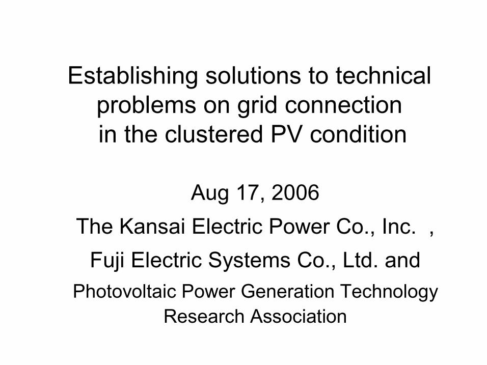
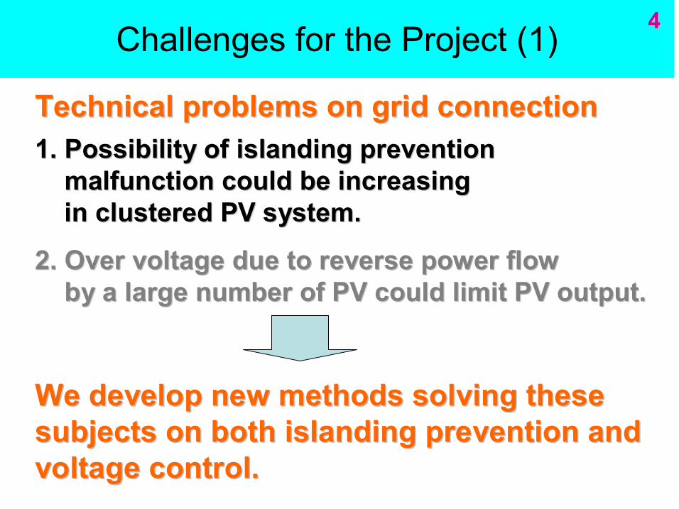
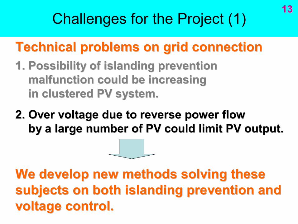
Challenges for the Project (1)
1. Possibility of islanding prevention 1. Possibility of islanding prevention malfunction could be increasing malfunction could be increasing in clustered PV system. in clustered PV system.
2. Over voltage due to reverse power flow 2. Over voltage due to reverse power flow by a large number of PV could limit PV output. by a large number of PV could limit PV output.
Technical problems on grid connection Technical problems on grid connection
We develop new methods solving these We develop new methods solving these subjects on both islanding prevention and subjects on both islanding prevention and voltage control. voltage control.
2 2
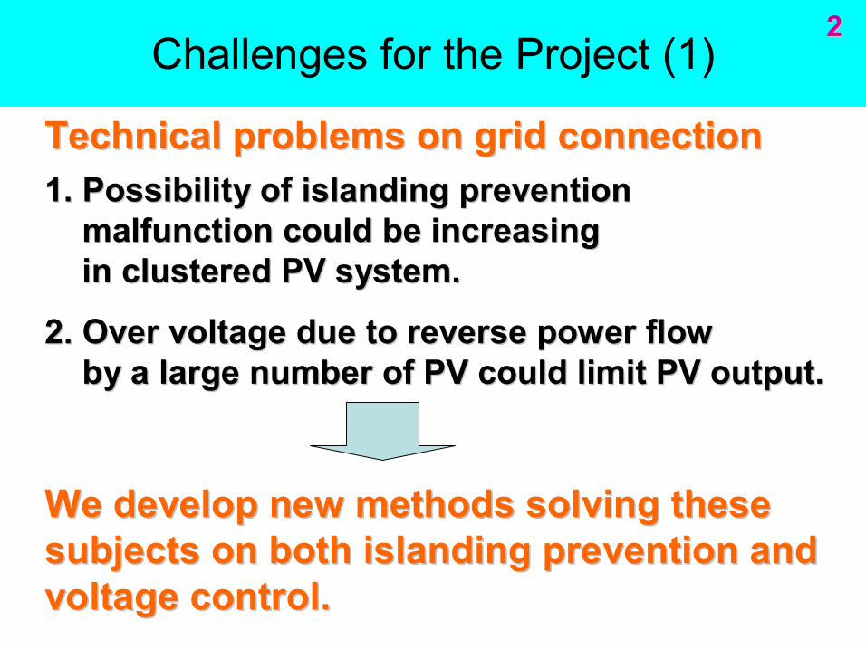
What is the clustered PV condition?
……
Customer connecting to the utility grid at higher voltage (eg.22kV)
Customer connecting to the utility grid at lower voltage (eg.400V)
The power utility’s substation
Distribution line
3 3
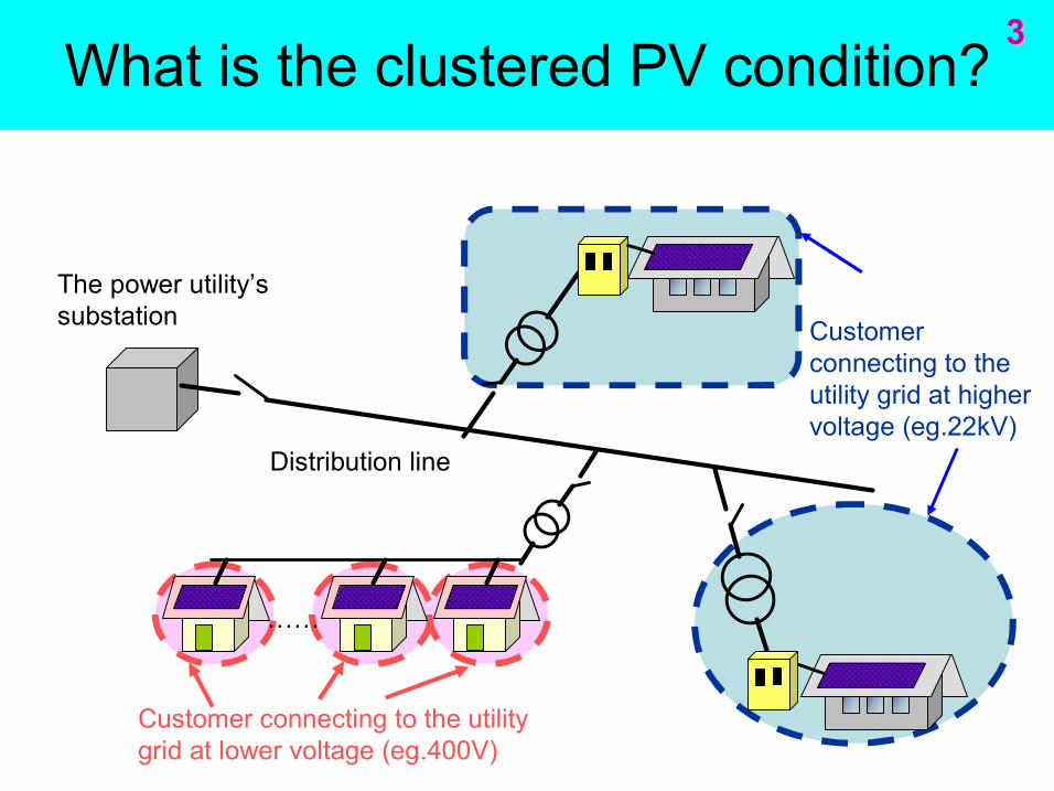
Challenges for the Project (1)
1. Possibility of islanding prevention 1. Possibility of islanding prevention malfunction could be increasing malfunction could be increasing in clustered PV system. in clustered PV system.
2. Over voltage due to reverse power flow 2. Over voltage due to reverse power flow by a large number of PV could limit PV output. by a large number of PV could limit PV output.
Technical problems on grid connection Technical problems on grid connection
We develop new methods solving these We develop new methods solving these subjects on both islanding prevention and subjects on both islanding prevention and voltage control. voltage control.
4 4
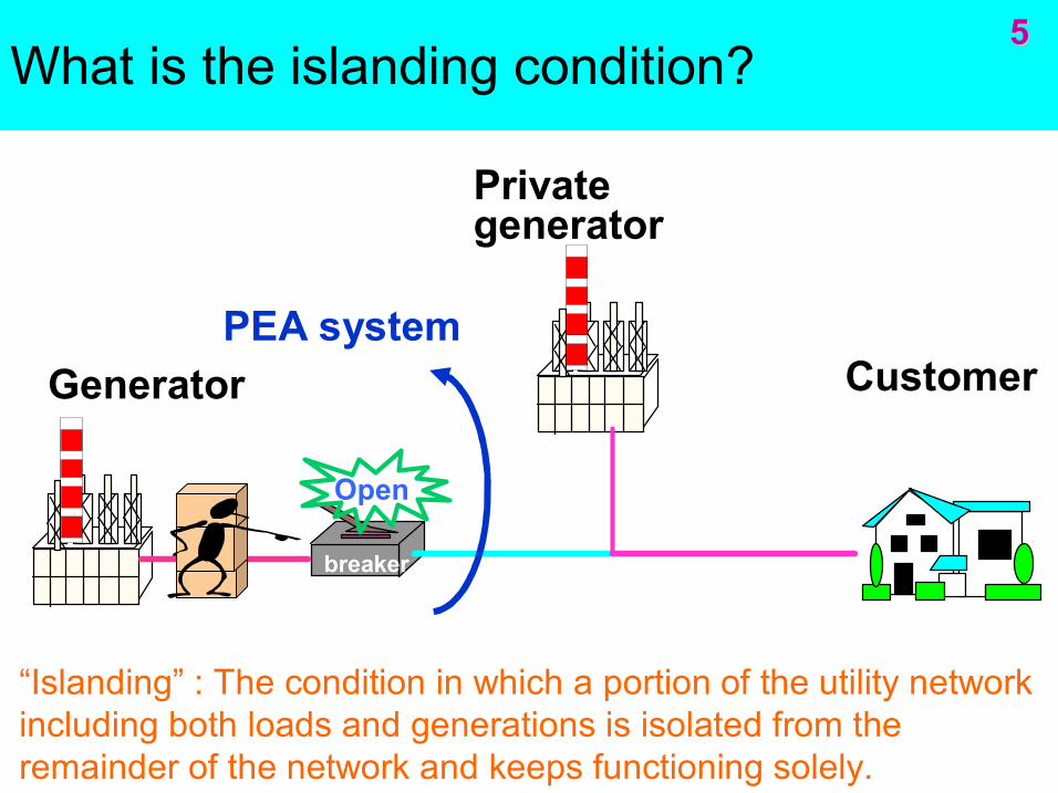
What is the islanding condition?
breaker
Open
Private generator
Customer Generator PEA system
“Islanding” : The condition in which a portion of the utility network including both loads and generations is isolated from the remainder of the network and keeps functioning solely.
5 5
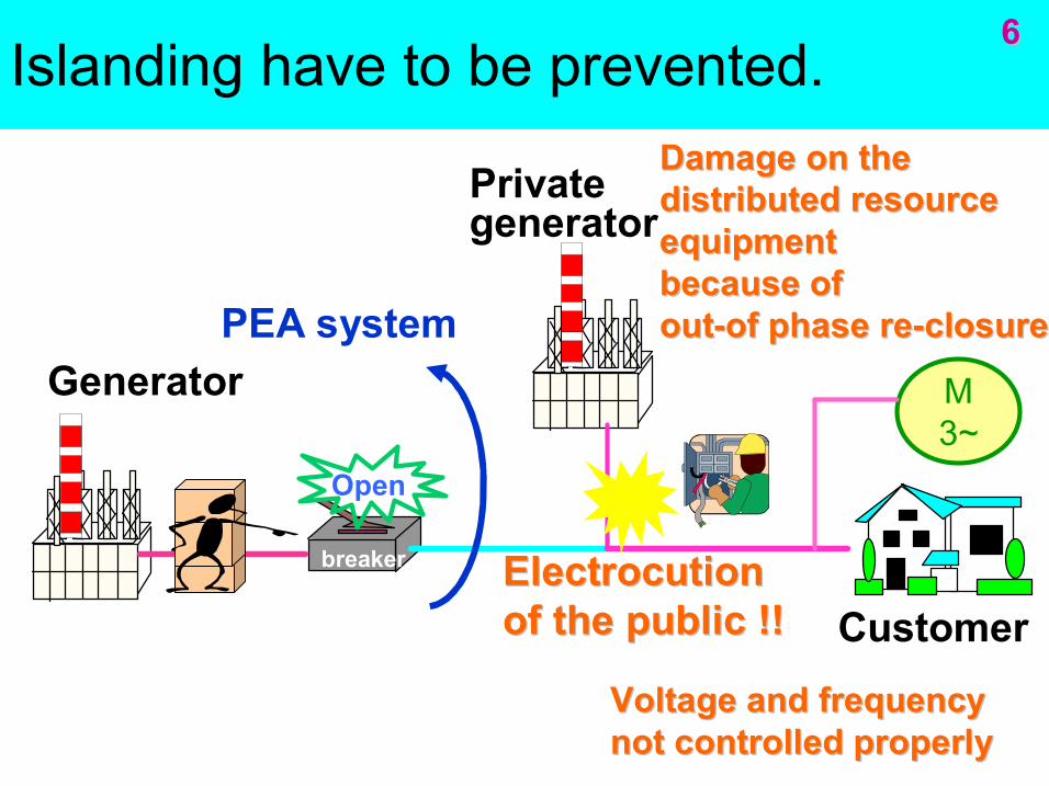
Islanding have to be prevented.
breaker
Open
Generator PEA system
M3~
Electrocution Electrocution of the public !! of the public !!
Voltage and frequency Voltage and frequency not controlled properly not controlled properly
Damage on the Damage on the distributed resource distributed resource equipment equipment because of because of out out of phase re of phase re closure closure
Private generator
Customer
6 6
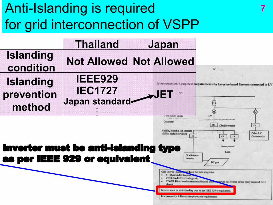
AntiIslanding is required for grid interconnection of VSPP
Thailand Japan Islanding condition Not Allowed Not Allowed
Islanding prevention method
IEEE929 IEC1727
Japan standard . . . . . .
JET
Inverter must be antiislanding type as per IEEE 929 or equivalent
7 7
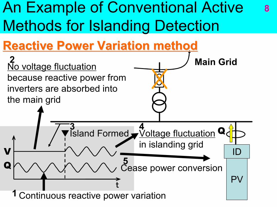
An Example of Conventional Active Methods for Islanding Detection
ID
PV
Main Grid
V Q
t
▼Island Formed
Cease power conversion
Continuous reactive power variation
No voltage fluctuation because reactive power from inverters are absorbed into the main grid
Reactive Power Variation method Reactive Power Variation method
Q
1
2
3
5
4 Voltage fluctuation in islanding grid
8 8
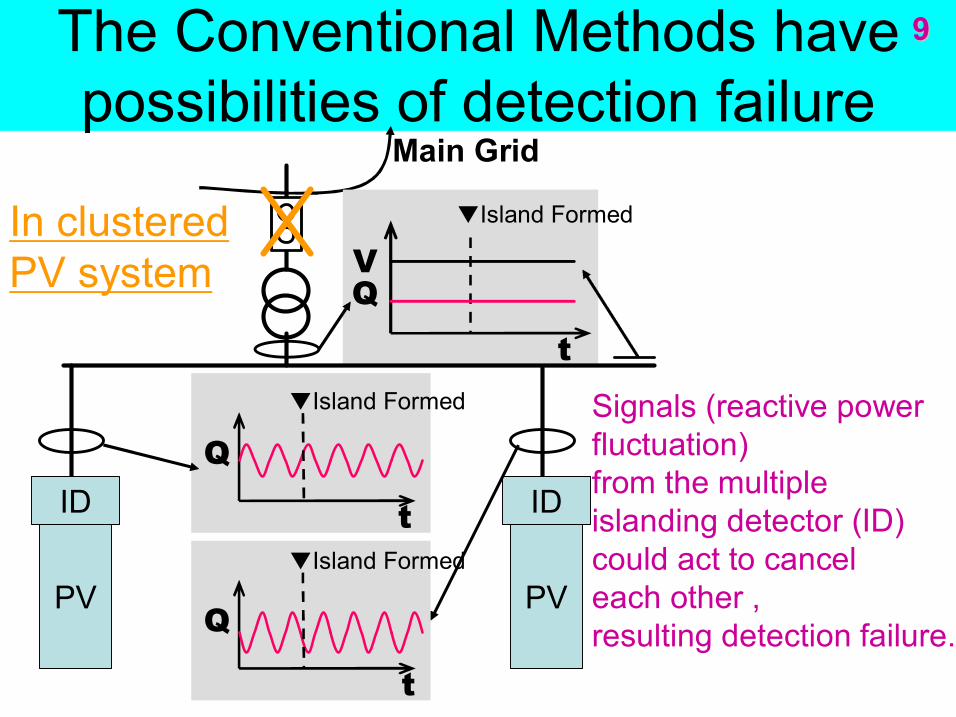
The Conventional Methods have possibilities of detection failure
ID
PV
Q ID
PV Q
t
Q
t
V In clustered PV system
t
Main Grid
▼Island Formed
▼Island Formed
▼Island Formed
Signals (reactive power fluctuation) from the multiple islanding detector (ID) could act to cancel each other , resulting detection failure.
9 9
CH8
-2
0
2
4
6
-1 0 1 2 3 4 5
CH2
-1
0
1
2
3
4
5
-1 0 1 2 3 4 5
CH8
-2
0
2
4
6
-1 0 1 2 3 4 5
FREQUENCY
49 49.2 49.4 49.6 49.8
50 50.2 50.4 50.6 50.8
51
-1 0 1 2 3 4 5
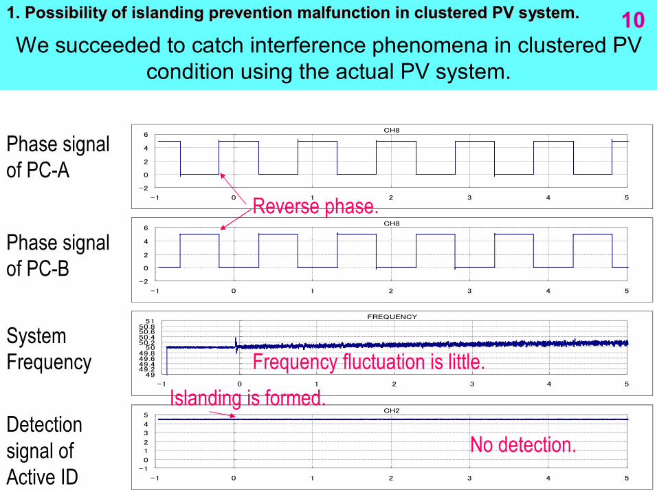
We succeeded to catch interference phenomena in clustered PV condition using the actual PV system.
Phase signal of PCA
Phase signal of PCB
System Frequency
Detection signal of Active ID
Reverse phase.
Frequency fluctuation is little.
No detection.
Islanding is formed.
10 10 1. Possibility of islanding prevention malfunction in clustered 1. Possibility of islanding prevention malfunction in clustered PV system. PV system.
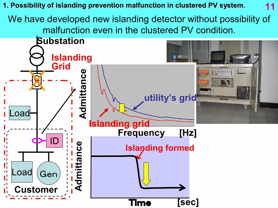
We have developed new islanding detector without possibility of malfunction even in the clustered PV condition.
Load
[Hz]
utility’s grid
Islanding grid
Substation
ID
Customer
Load
Islanding Grid
Frequency
Gen
Time
Adm
ittance
Islanding formed
Adm
ittance
11 11 1. Possibility of islanding prevention malfunction in clustered 1. Possibility of islanding prevention malfunction in clustered PV system. PV system.
[sec]
islanding formed
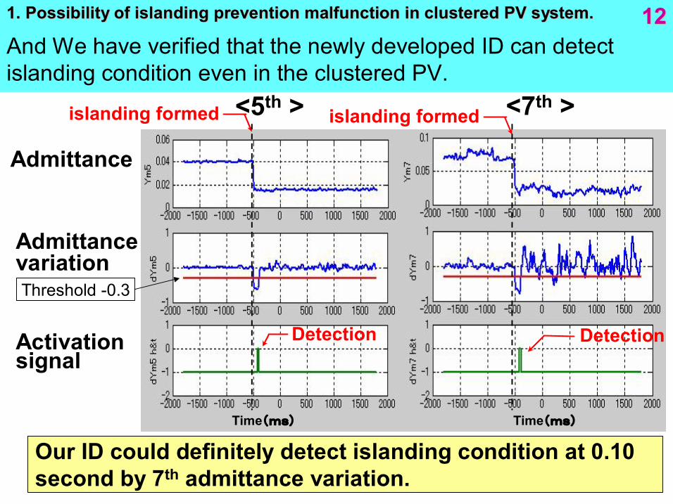
Our ID could definitely detect islanding condition at 0.10 second by 7 th admittance variation.
Time(ms)
<5 th >
Admittance
Detection Detection
<7 th >
Admittance variation
Activation signal
islanding formed
Time(ms)
Threshold 0.3
And We have verified that the newly developed ID can detect islanding condition even in the clustered PV.
12 12 1. Possibility of islanding prevention malfunction in clustered 1. Possibility of islanding prevention malfunction in clustered PV system. PV system.
Challenges for the Project (1)
1. Possibility of islanding prevention 1. Possibility of islanding prevention malfunction could be increasing malfunction could be increasing in clustered PV system. in clustered PV system.
2. Over voltage due to reverse power flow 2. Over voltage due to reverse power flow by a large number of PV could limit PV output. by a large number of PV could limit PV output.
Technical problems on grid connection Technical problems on grid connection
We develop new methods solving these We develop new methods solving these subjects on both islanding prevention and subjects on both islanding prevention and voltage control. voltage control.
13 13
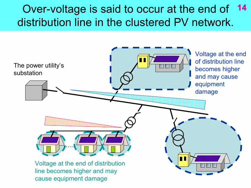
Overvoltage is said to occur at the end of distribution line in the clustered PV network.
14 14
……
The power utility’s substation
Voltage at the end of distribution line becomes higher and may cause equipment damage
Voltage at the end of distribution line becomes higher and may cause equipment damage
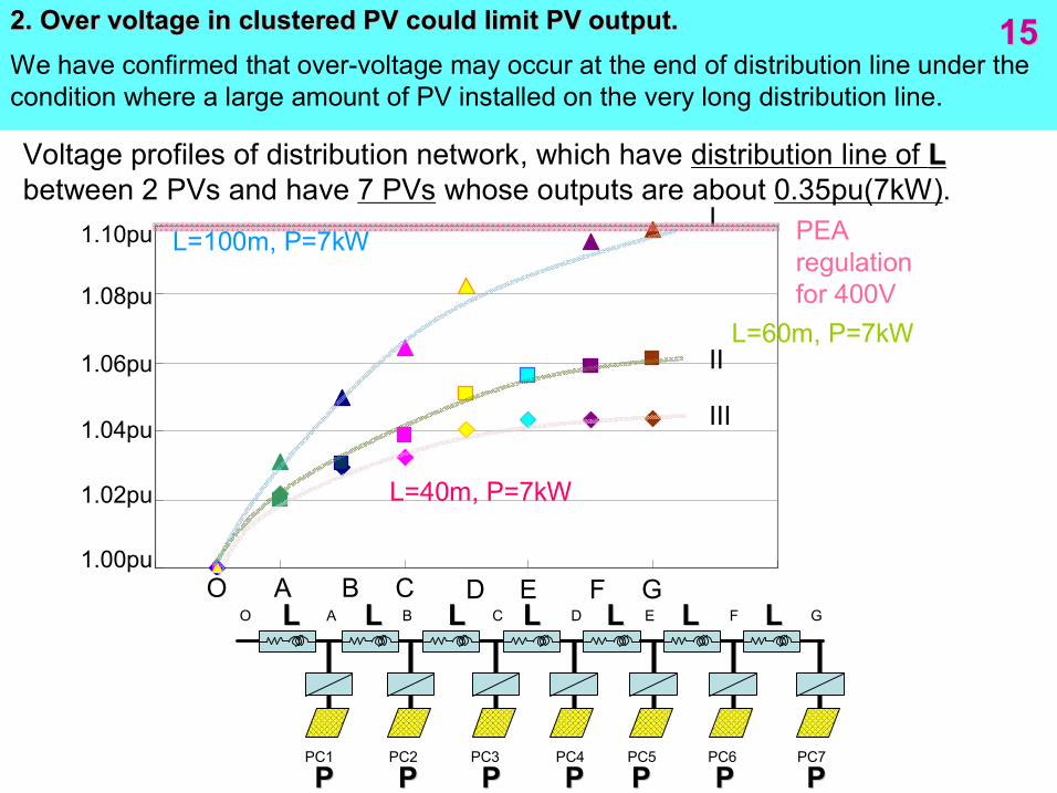
We have confirmed that overvoltage may occur at the end of distribution line under the condition where a large amount of PV installed on the very long distribution line.
15 15
O A B C D E F G 1.00pu
1.02pu
1.04pu
1.06pu
1.08pu
1.10pu
Voltage profiles of distribution network, which have distribution line of L L between 2 PVs and have 7 PVs whose outputs are about 0.35pu(7kW).
I
II
III
PEA regulation for 400V
L L
2. Over voltage in clustered PV could limit PV output. 2. Over voltage in clustered PV could limit PV output.
L=100m, P=7kW
O A B C D E F G
PC1 PC2 PC3 PC4 PC5 PC6 PC7
L=60m, P=7kW
L=40m, P=7kW
L L L L L L L L L L L L
P P P P P P P P P P P P P P
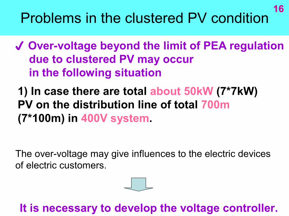
Problems in the clustered PV condition 16 16
p Overvoltage beyond the limit of PEA regulation due to clustered PV may occur in the following situation
1) In case there are total about 50kW (7*7kW) PV on the distribution line of total 700m (7*100m) in 400V system.
It is necessary to develop the voltage controller.
The overvoltage may give influences to the electric devices of electric customers.
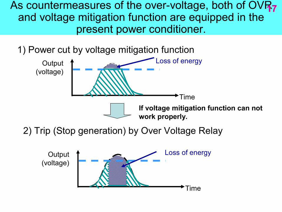
As countermeasures of the overvoltage, both of OVR and voltage mitigation function are equipped in the
present power conditioner.
17 17
2) Trip (Stop generation) by Over Voltage Relay
1) Power cut by voltage mitigation function
Time
Output (voltage)
Time
Output (voltage)
Loss of energy
Loss of energy
If voltage mitigation function can not work properly.
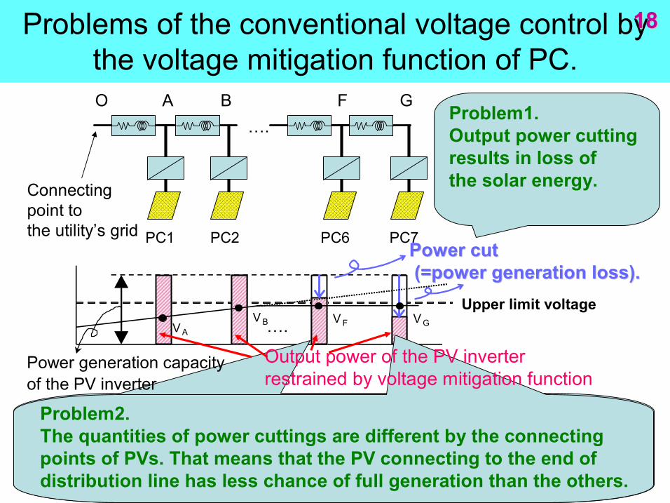
Problems of the conventional voltage control by the voltage mitigation function of PC.
18 18
Upper limit voltage
Power cut Power cut (=power generation loss). (=power generation loss).
V A V B V F V G
O A B F G
PC1 PC2 PC6 PC7
….
….
Problem1. Output power cutting results in loss of the solar energy.
Problem2. The quantities of power cuttings are different by the connecting points of PVs. That means that the PV connecting to the end of distribution line has less chance of full generation than the others.
Output power of the PV inverter restrained by voltage mitigation function
Power generation capacity of the PV inverter
Connecting point to the utility’s grid
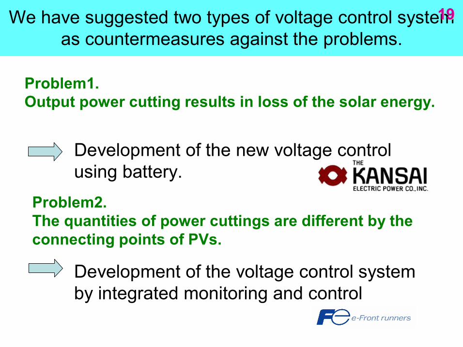
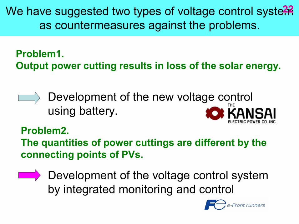
We have suggested two types of voltage control system as countermeasures against the problems.
19 19
Problem1. Output power cutting results in loss of the solar energy.
Problem2. The quantities of power cuttings are different by the connecting points of PVs.
Development of the new voltage control using battery.
Development of the voltage control system by integrated monitoring and control
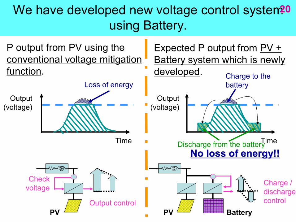
We have developed new voltage control system using Battery.
20 20
Time
Output (voltage)
Loss of energy
P output from PV using the conventional voltage mitigation function.
Time
Output (voltage)
Charge to the battery
Expected P output from PV + Battery system which is newly developed.
Discharge from the battery No loss of energy!! No loss of energy!!
Check voltage
Output control
Charge / discharge control
PV PV Battery
System Voltage
380
390
400
410
420
430
440
12:00:00 15:00:00 18:00:00 Time
Sys
tem
Voltag
e(V
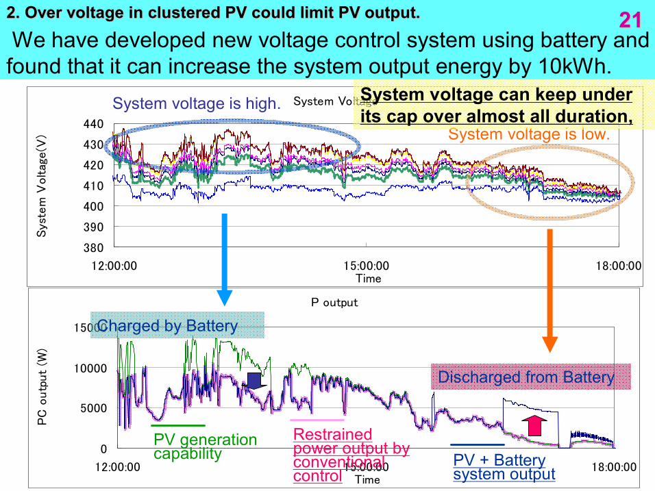
) We have developed new voltage control system using battery and found that it can increase the system output energy by 10kWh.
21 21
P output
0
5000
10000
15000
12:00:00 15:00:00 18:00:00 Time
PC
outp
ut
(W)
PV generation capability
Restrained power output by conventional control
PV + Battery system output
Charged by Battery
Discharged from Battery
System voltage is high.
System voltage is low.
System voltage can keep under its cap over almost all duration,
2. Over voltage in clustered PV could limit PV output. 2. Over voltage in clustered PV could limit PV output.
We have suggested two types of voltage control system as countermeasures against the problems.
22 22
Development of the new voltage control using battery.
Development of the voltage control system by integrated monitoring and control
Problem1. Output power cutting results in loss of the solar energy.
Problem2. The quantities of power cuttings are different by the connecting points of PVs.
O A B F G
PC1 PC2 PC6 PC7
….
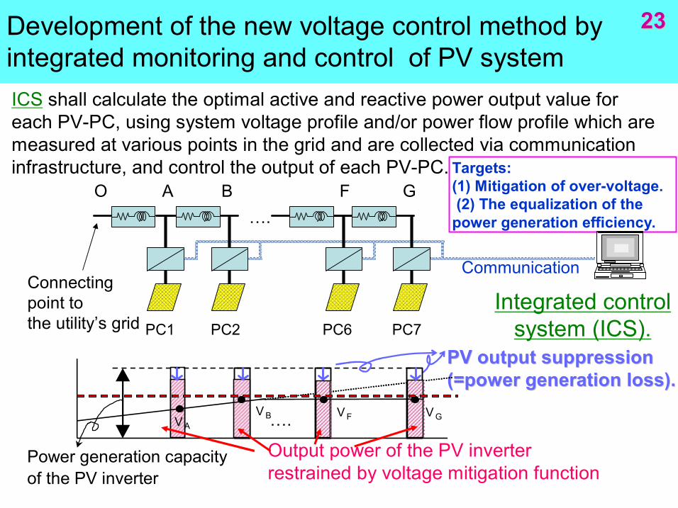
Development of the new voltage control method by integrated monitoring and control of PV system ICS shall calculate the optimal active and reactive power output value for each PVPC, using system voltage profile and/or power flow profile which are measured at various points in the grid and are collected via communication infrastructure, and control the output of each PVPC. Targets:
(1) Mitigation of overvoltage. (2) The equalization of the power generation efficiency.
Integrated control system (ICS).
Communication
PV output suppression PV output suppression (=power generation loss). (=power generation loss).
V A V B V F ….
Output power of the PV inverter restrained by voltage mitigation function
Power generation capacity of the PV inverter
Connecting point to the utility’s grid
V G
23 23
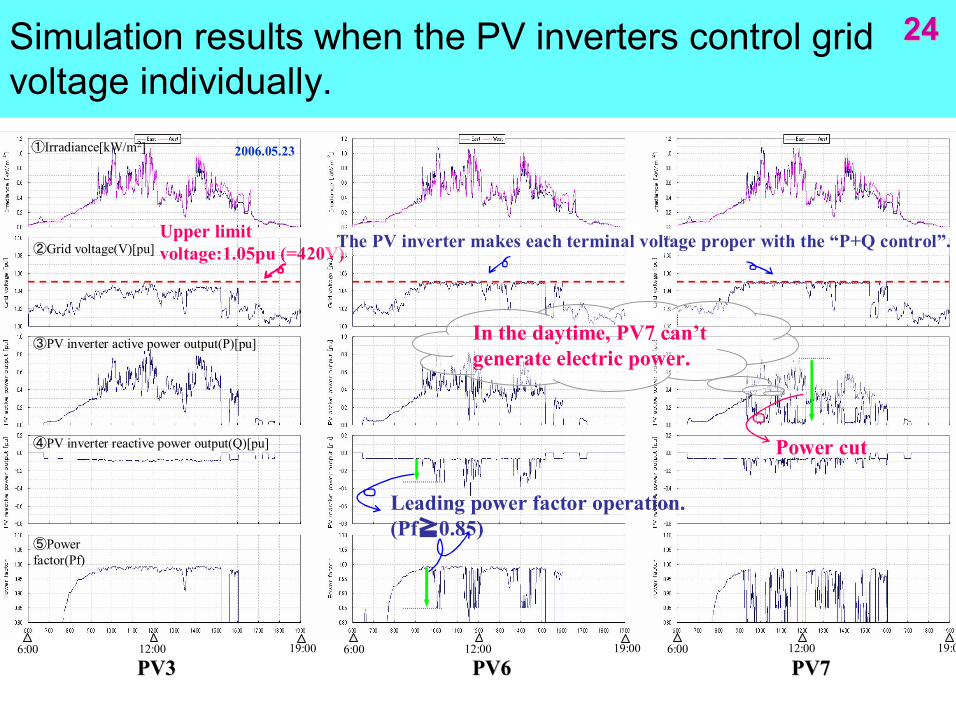
Simulation results when the PV inverters control grid voltage individually.
24 24
①Irradiance[kW/m 2 ]
②Grid voltage(V)[pu]
③PV inverter active power output(P)[pu]
④PV inverter reactive power output(Q)[pu]
⑤Power factor(Pf)
Upper limit voltage:1.05pu (=420V)
PV3 PV3 PV6 PV6 PV7 PV7
The PV inverter makes each terminal voltage proper with the “P+Q control”.
Power cut
In the daytime, PV7 can’t generate electric power.
6:00 19:00 12:00 6:00 19:00 12:00 6:00 19:00 12:00
Leading power factor operation. (Pf≧0.85)
2006.05.23
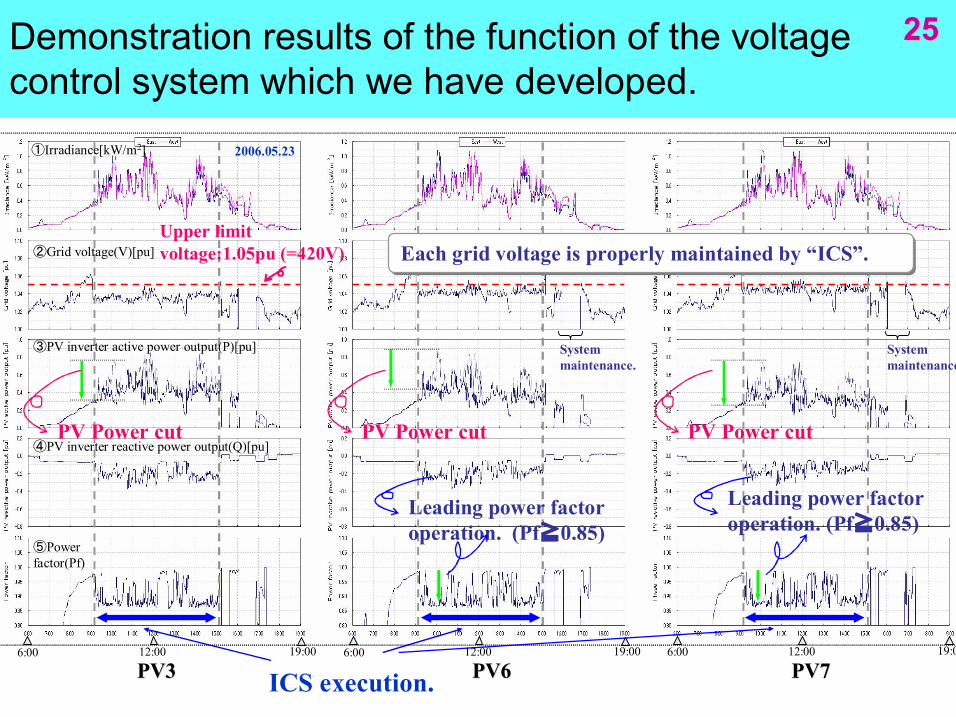
Demonstration results of the function of the voltage control system which we have developed.
25 25
PV3 PV3 PV6 PV6 PV7 PV7
Each grid voltage is properly maintained by “ICS”. Each grid voltage is properly maintained by “ICS”.
①Irradiance[kW/m 2 ]
②Grid voltage(V)[pu]
③PV inverter active power output(P)[pu]
④PV inverter reactive power output(Q)[pu]
⑤Power factor(Pf)
System maintenance.
Leading power factor operation. (Pf≧0.85)
PV Power cut
System maintenance.
Leading power factor operation. (Pf≧0.85)
PV Power cut PV Power cut
6:00 19:00 12:00 6:00 19:00 12:00 6:00 19:00 12:00
ICS execution.
2006.05.23
Upper limit voltage:1.05pu (=420V)
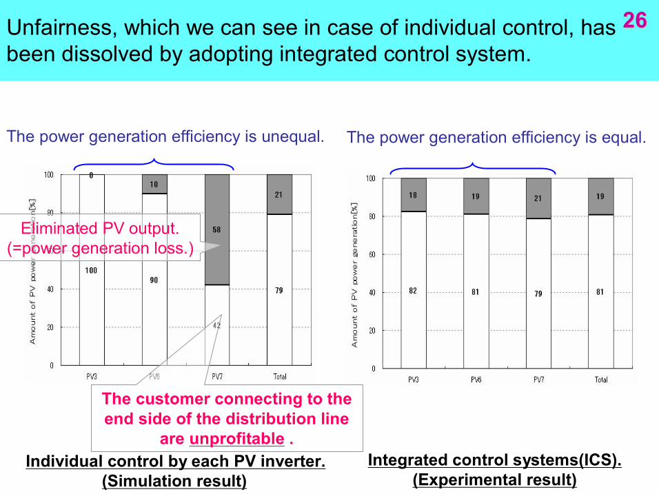
Unfairness, which we can see in case of individual control, has been dissolved by adopting integrated control system.
26 26
Integrated control systems(ICS). (Experimental result)
Individual control by each PV inverter. (Simulation result)
The power generation efficiency is unequal. The power generation efficiency is equal.
The customer connecting to the end side of the distribution line
are unprofitable .
Eliminated PV output. (=power generation loss.)
27 27 Conclusion Conclusion
> We have obtained significant results which will contribute to introduction of further PV systems in both of Thailand and Japan.
The End
Thank you!