Embed Size (px)
Citation preview
PV System Commissioning
solarprofessional.com | S o l a r Pr o 35
Understanding and paying attention to PV commissioning is important to the industry. If the PV industry is to continue to expand and become a significant part of the US energy portfolio, short- and long-term sys-tem performance is critical to maintaining public confidence and goodwill. Already,
many interested parties are making concerted efforts to maintain the quality control of installed systems. Power Purchase Agreement (PPA) providers, for example, must protect their investments; manufacturers want to see the PV market grow; and legislators and rebate administrators need to encourage responsible industry growth. Integrators, who play such a large role in the story, must do their part to ensure the safety, quality and performance of installed PV systems.
Commissioning is a way to formalize quality control of installed PV systems. The process ensures that systems are safe and high performing. It encourages integrators to be responsible for their installations and facilitates project closeout and prompt payment. Successful commissioning leads to satisfied installers, employers and system owners. Satisfied customers become repeat customers and lead to new clients. Seen in this light, commissioning is essential to the growth of the PV industry and to the overarching goal of installing more renewable energy systems.
Think this is an overstatement? Consider what commis-sioning prevents. It protects against fires, shocks and injury.
It keeps customers happy and minimizes callbacks. It ensures that a lot of silicon, aluminum, glass, steel, copper, dollars and effort are not wasted on nonperforming or underperforming systems. Commissioning guards against a lack of public con-fidence in PV and renewable energy technologies.
This article covers the commissioning of both residen-tial and commercial scale grid-tied PV systems in detail. Although it does not specifically address off-grid, battery-backup or vehicle PV systems, many of the same principles apply. Similarly, while large utility scale PV systems are not specifically exemplified, the commercial scale procedures are easily scalable.
The building commissioning processThe commissioning process is typically applied to entire buildings. To set a framework for PV commissioning, it is useful to examine the total building commissioning process. The Building Commissioning Association (BCA) defines commissioning in its sample specification as: “a quality-oriented process for achieving, verifying and documenting that the performance of facilities, systems and assemblies meet defined objectives and criteria. The commissioning process begins at project inception (dur-ing the pre-design phase) and continues through the life of the facility. The commissioning process includes specific tasks to be conducted during each phase in order to verify that design, construction and training meet the owner’s project requirements.”
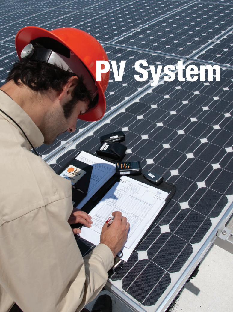
PV System CommissioningPV is simple: Turn it on; have sun; make power.
Commissioning may seem like an unnecessarily
time-consuming and complex exercise, but it is a
critical part of a well-installed system.
sha
wn
sch
rein
er.
co
m
By Blake Gleason
36 S o l a r Pr o | october/November 2009
PV System Commissioning
Further, the BCA outlines the basic tasks of commissioning:
• Verifythatapplicableequipmentandsystemsare installed according to the contract documents, manufacturer’s recommendations and industry accepted minimum standards.
• Verifythatinstallingcontractorsperformadequate operation checkout.
• Verifyanddocumentproperperformanceof equipment and systems.
• Verifythattheoperationsandmaintenance(O&M) documentation left on-site is complete.
• Verifythattheowner’soperatingpersonnelare adequately trained.
commissioning pV sYsTemsTypically, system owners have specific goals in mind for their PV system. These might include reducing electric bills by a certain percentage, maximizing the power output from available roof space or maximizing return on their PV investment. These goals are known as the owner’s project requirements. The PV system designers then devise a strategy to meet these requirements. This strat-egy, including documents describing the intended system components and calculated expected performance out-put, is called the basis of design, which should help guide the PV commission-ing process.
At the most basic level, commission-ing ensures that the owner’s require-ments have been met. Most of the PVsystem commissioning will occur after installation is complete and before proj-ect closeout. It should include the fol-lowing elements:
• Verifythattheinstallationis complete.
• Verifythattheinstallationis safe.
• Verifythattheinstallationis aesthetically acceptable.
• Verifythatallcomponentsof the installation are robust and permanent.
• Documentas-builtconditions.• Verifysystemperformance.• Verifypropersystemoperation.
• Establishperformancebenchmarks.• Completeanyrequiredacceptancedocumentation.• Trainthesystemowneronbasicsystemoperation.
safeTY in commissioningYou should take the same safety precautions that you use during PV installation when commissioning the sys-tem. Fall protection, ladder safety, electrical safety, per-sonal protective equipment and common sense are all required. When commissioning personnel are not part of the installation crew, they are not familiar with the hazards on a particular job site. They may not be familiar with best practice construction safety c o n t i n u e d o n pa g e 3 8
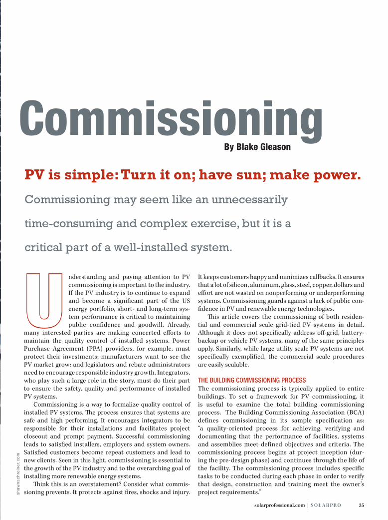
Quality assurance Commissioning is a process that starts during predesign and proceeds through PV system acceptance. Far more than an inverter start-up sequence, commissioning documents the as-built condition of the system—like this installation by Sun Light & Power in Berkeley, CA—and ensures that the installation is safe, durable and performing properly.
sha
wn
sch
rein
er.
co
m
38 S o l a r Pr o | october/November 2009
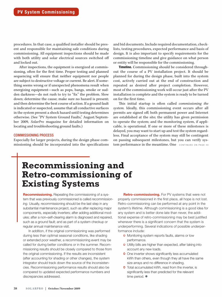
procedures. In that case, a qualified installer should be pres-ent and responsible for maintaining safe conditions during commissioning. All equipment inspections should be made with both utility and solar electrical sources switched off and locked out.
After inspections, the equipment is energized at commis-sioning, often for the first time. Proper testing and planned sequencing will ensure that neither equipment nor people are subject to destructive voltage or current. Be alert. If some-thing seems wrong or if unexpected phenomena result when energizing equipment—such as pops, bangs, smoke or sud-den darkness—do not rush to try to “fix” the problem. Slow down; determine the cause; make sure no hazard is present; and then determine the best course of action. If a ground fault is indicated or suspected, assume that all conductive surfaces in the system present a shock hazard until testing determines otherwise. (See “PV System Ground Faults,” August/Septem-ber 2009, SolarPro magazine for detailed information on locating and troubleshooting ground faults.)
commissioning processEspeciallyforlargerprojects,duringthedesignphasecom-missioning should be incorporated into the specifications
and bid documents. Include required documentation, check-lists, testing procedures, expected performance and basis of design. It is also important to specify requirements for the commissioning timeline and give guidance on what person or entity will be responsible for the commissioning.
Timeline. Commissioning should be considered through-out the course of a PV installation project. It should be planned for during the design phase, built into the system cost, actively carried out at the end of construction and repeated as desired after project completion. However, most of the commissioning work will occur just after the PV installation is complete and the system is ready to be turned on for the first time.
This initial startup is often called commissioning the system. Ideally, this commissioning event occurs after all permits are signed off; both permanent power and Internet are established at the site; the utility has given permission to operate the system; and the monitoring system, if appli-cable, is operational. If one or more of these milestones is delayed, you may want to start up and test the system regard-less. Final acceptance of the system may still be contingent on passing subsequent milestones, but you can verify sys-temperformanceinthemeantime.One c o n t i n u e d o n pa g e 4 0
PV System Commissioning
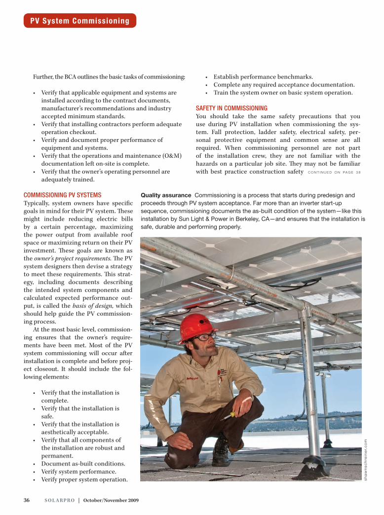
Recommissioning and Retro-commissioning of Existing SystemsRecommissioning. Repeating the commissioning of a sys-tem that was previously commissioned is called recommission-ing. usually, recommissioning should be the last step in any substantial maintenance project, such as after replacing major components, especially inverters; after adding additional mod-ules; after a non–self-clearing alarm is diagnosed and repaired, such as a ground fault; and as part of a system checkup or regular annual maintenance visit.
in addition, if the original commissioning was performed during less than optimal seasonal conditions, like shading or extended poor weather, a recommissioning event may be called for during better conditions or in the summer. Recom-missioning results should be closely compared to those from the original commissioning. if the results are inconsistent (after accounting for shading or other changes), the system integrator should track down the source of the inconsisten-cies. Recommissioning performance results should also be compared to updated expected performance numbers and discrepancies addressed.
Retro-commissioning. For pV systems that were not properly commissioned in the first place, all hope is not lost. Retro-commissioning can be performed at any point in the system’s lifetime. although commissioning is a good idea for any system and is better done late than never, the addi-tional expense of retro-commissioning may be best justified whenever there is a significant concern that the system is underperforming. Several indications of possible underper-formance include:
• Monitoring system reports faults, alarms or low performance.
• utility bills are higher than expected, after taking into account any new loads.
• one inverter shows significantly less accumulated kWh than others, even though they all have the same size arrays and no difference in shading.
• total accumulated kWh, read from the inverter, is significantly less than predicted for the relevant time period. {
40 S o l a r Pr o | october/November 2009
exception to this timeline is for systems that have a “burn in” period, such as thin film amorphous silicon systems. These systems will experience a significant, but expected, drop in production over the first few weeks and months of operation. Therefore, performance measurements made at initial system startup will be arti-ficially high. Recommissioning is required after this burn-in period.
Be sure to schedule the commission-ing as soon as possible after PV system construction is complete, but within a suitable window of weather. It does not make sense, for example, to commission when there is irradiance of less than 400 W/m2 in the array plane. Not only must the weather be good, but the time of day must also be appropriate.
Especially on small projects, thetendency is to try to commission the system at the end of the last day of installation. This strategy is efficient butnoteffective.Often, thesun is toolow in the sky to provide sufficient irra-diance for proper performance verifi-cation. Shading is also more likely at the end of the day, and any shade on the array makes performance verifi-cation difficult. Finally, commission-ing demands focus, clear thinking and sufficient time. If the end of the day is near, the crew may be cold, hot, hungry, thirsty or just ready to go home. None of these conditions are likely to produce accurate commissioning results. It is better to clean up, go home and come back another day when the sun is out and minds are fresh.
Who does it? For commissioning to be most effective, the commissioning party should not be inclined towards a cur-sory process with a guaranteed positive outcome. The con-tractor who installed the system will usually have this bias. Ideally, the commissioning party should represent the system owner, not the installer, and should be able to act completely in the owner’s interest without conflict. For large systems, the owner should contract with an outside commissioning specialist to oversee the commissioning process.
If the scope of the project is not sufficient to bring in an outside specialist and a direct representative of the owner is not available, commissioning should be performed by an objective party under the original system integration con-tract. For small commercial projects, for example, an engi-neer or system designer might be the best choice for the job.
Eventhoughtheengineerworksfortheintegrator,heorsheis at least one level removed from the physical project.
At a bare minimum, a person with sufficient knowledge about PV in general and the system being commissioned in particular must undertake commissioning. This is true even for small residential projects, where the best person to commission might be the crew leader who was in charge of the installation. As someone with a supervisory role, the crew leader can dele-gate any corrective tasks and focus on effective commissioning, leaving behind a system to be proud of. Regardless of the level of objectivity, whoever carries out the commissioning must have the proper tools and sufficient training.
Documentation. The commissioning agent must start with all of the available system documentation. Before undertak-ing commissioning, relevant documentation such as the following must be on hand: drawings, ideally as-built; cut sheets for modules and inverters; specifications, especially as they pertain to commissioning; special requirements or forms for rebate programs or other incentives; and equip-ment manuals. c o n t i n u e d o n pa g e 4 2
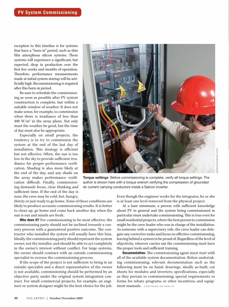
Torque settings Before commissioning is complete, verify all torque settings. The author is shown here with a torque wrench verifying the compression of grounded dc current carrying conductors inside a Satcon inverter.
sha
wn
sch
rein
er.
co
m
PV System Commissioning
42 S o l a r Pr o | october/November 2009
The commissioning agent must also understand what deliverables are required at the end of the process. For a municipal or federal PV project, for example, the deliver-ables are often extensive and detailed in the bid package. For a residential project, the commissioning documentation may be part of a post-installation punch list that remains in the customer file for internal use.
commissioning Tasks For a small PV system, commissioning might mean that the installer takes a step back, looks over the installation, tests voltage at a few points, watches as everything turns on successfully and verifies system performance. At the other extreme, for a large PV plant there might be a dedicated commissioning team with a multi-day, multi-faceted com-missioning agenda, including follow-up activities and writ-ten reports. Whatever the scale, and whoever does the com-missioning, the basic tasks and goals of the process remain the same.
Verify that the installation is complete. Are all components permanently installed? Is everything wired completely? Per-manent utility power should be connected at the site. In addition, if Web based monitoring is being used, the Internet connectionshouldbeoperational.Examinethemostrecentinstallation punch list to make sure all items are complete.
Verify that the installation is safe. Has the permit been signed off ? Are the mechanical and structural systems ade-quate and built according to plan? Has any required water-proofing been completed satisfactorily? Has the electrical design been adapted properly?
A few common problem areas are worth checking:
• Makesureworkingclearancesaremaintained.• Verifythatallmetallicsurfacesthatmightbecome
energized are grounded. • Ensurethatwireandconduitsizesinstalledinthe
field are as shown on the plans.
Verify that the installation is aesthetically acceptable. Check to see that the PV array is only as visible as it was designed to be. Verify that module lines are straight and parallel to roof features, especially where visible from the ground or high traffic areas. Is all other equipment installed plumb, level and with good workmanship?
Are any required aesthetic treatments complete? If this was part of the contract, for example, inspect whether con-duit systems and disconnects are painted to match the walls. Ensure that PV array skirts, where required, are installedand satisfactory. Check that inverter fences or enclosures are built as designed.
Verify that the installation is robust and permanent. Ensurethat all outdoor equipment is designed to withstand the
elements and the environment it will be subjected to for the design life of the system, usually 30-plus years for PV sys-tems. Fasteners should be stainless steel, and steel rack ele-mentsshouldbehot-dippedgalvanizedorbetter.Dissimilarmetals must be isolated to avoid galvanic corrosion. Wiring and raceways must be suitable for their location. Sunlight resistant wire is required under arrays, for example, and electrical metallic tubing (EMT), intermediate metal con-duit(IMC)orrigidmetalconduit(RMC)isrequiredontheroof.Make sure thatNEC required labeling is present and that it is made of appropriate materials, such as engraved metal or plastic.
Document as-built conditions. During the visual systemreview, note anything out of the ordinary. c o n t i n u e d o n pa g e 4 4
PV System Commissioning
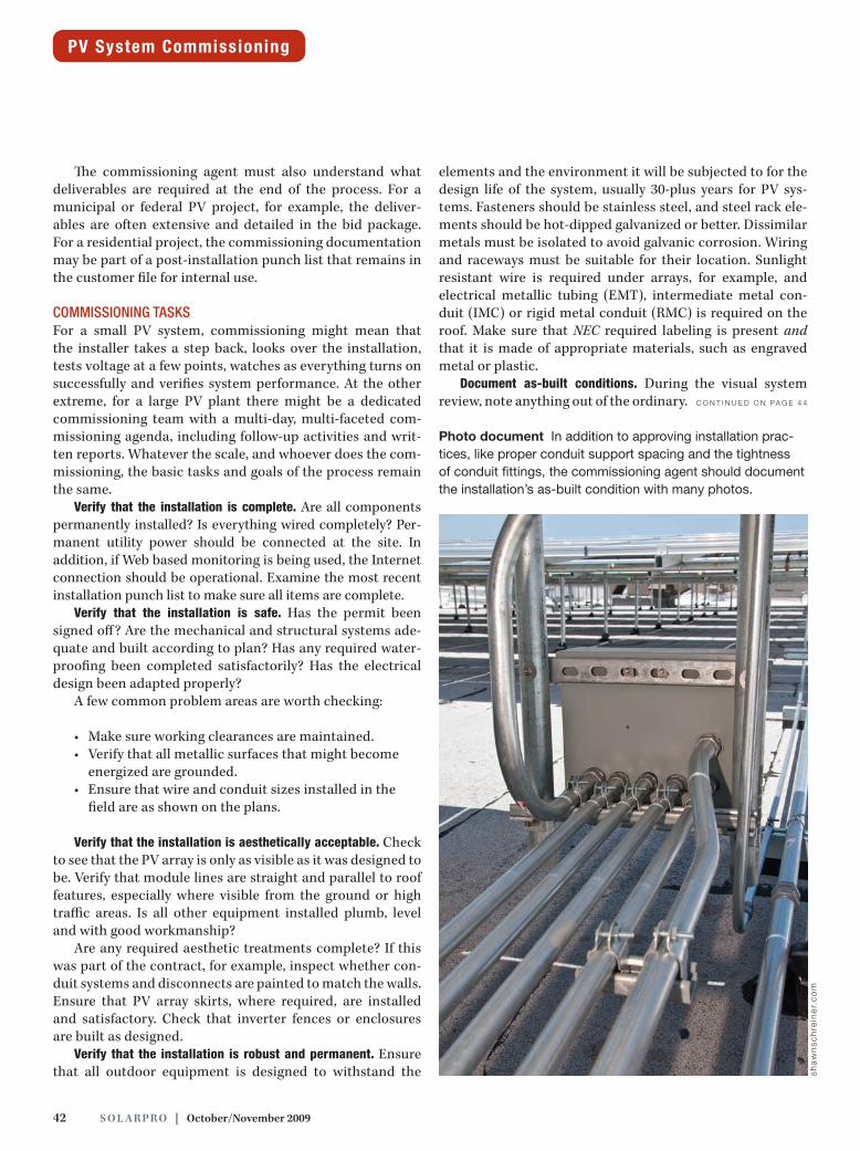
Photo document In addition to approving installation prac-tices, like proper conduit support spacing and the tightness of conduit fittings, the commissioning agent should document the installation’s as-built condition with many photos.
sha
wn
sch
rein
er.
co
m
44 S o l a r Pr o | october/November 2009
Each questionable item should bewritten down and pho-tographed, with the photo location marked on a roof plan or other appropriate drawing. Take pictures of all arrays, ideally from at least two angles. Also take pictures of con-duit runs, combiner boxes, disconnects, inverters and the interconnection.
Verify that the module layout matches the approved roof plan drawing. Note any discrepancies on the drawing. Verify that the module string layout is as shown on the as-built string diagram, including consistency of wire and string numbering. Accurate string diagrams are extremely help-ful for future maintenance and troubleshooting. For smaller systems, if a string diagram does not exist, identify the string locations and document them on the roof plan. For large sys-tems missing a string layout, identify this as an action item for the integrator.
Documentthemodelnumberandquantityofthemod-ules, inverters, combiner boxes, disconnects and monitor-ing system.
expecTed performance Probably the most difficult and the most important aspect of commissioning a PV system is evaluating whether it is performing as well as it should be. First, the expected per-formance needs to be determined. Then, the actual perfor-mance needs to be measured.
To determine the expected per-formance of the PV system, refer to the basis of design. Assuming that the system was sized properly in the design phase, it should meet the owner’s requirements for energy production. Based on the equipment specified, estimate the monthly, annual and lifetime energy output of the system.
ManysoftwarepackagesandWebbased calculators can simplify this task. For example, you can use the free PVWATTS Web based calcula-tor to get a very quick energy harvest estimate by inputting the peak dc
rating of the system, the system location and the array orien-tation; monthly and annual kWh performance estimates are given as an output. The California Solar Initiative (CSI) rebate calculators are also available to the general public, although they are of interest primarily to California utility customers. Forexample,theCSIExpectedPerformance-BasedBuydown(EPBB) calculator (see Resources) allows for the input ofspecific module and inverter combinations, monthly shad-ing data, as well as information about the site location and array orientation. It does not, however, allow changing other assumptions such as module mismatch, wire losses and sys-temavailability.EPBBusesPVWATTSforitsbackend.
Manyintegrators,PPAprovidersandthird-partysoftwaredevelopers provide performance calculators. Some products available for purchase, like Clean Power Finance and Quick-Quotes from Clean Power Research, include updated elec-trical rate schedules and other information not only to esti-mate PV production but also to provide detailed financial analyses. Fortunately, for commissioning purposes, all that you need are the power and energy output of the PV system.
Since all of the energy calculators are based on average historical weather data, a PV system should not be expected to produce exactly the amount predicted by the energy cal-culator in a given day, week or month. The longer the inter-val, the better the actual performance should match the pre-
dicted performance. While there is significant variation in weather even from year to year, certainly after 5 or 10 years the system’s total accumulated energy production should match the predicted output. Unfortunately, 10 years is too long to wait to make sure the system is working as intended.
At initial system commission-ing, very little historical produc-tion data is available. Therefore, the single best metric to verify system performance in the short term is the instantaneous power output of the system. The following process is one way to estimate the expected value of the system power output at any moment.
1. Determine the peak dc power rating of the system. This value will be the sum of the power outputs of ideal individual modules at STC. Obtaining this number is straight-forward, because it is the product of the nameplate module rating (PSTC ) and the total quantity of modules.
PV System Commissioning
sha
wn
sch
rein
er.
co
m
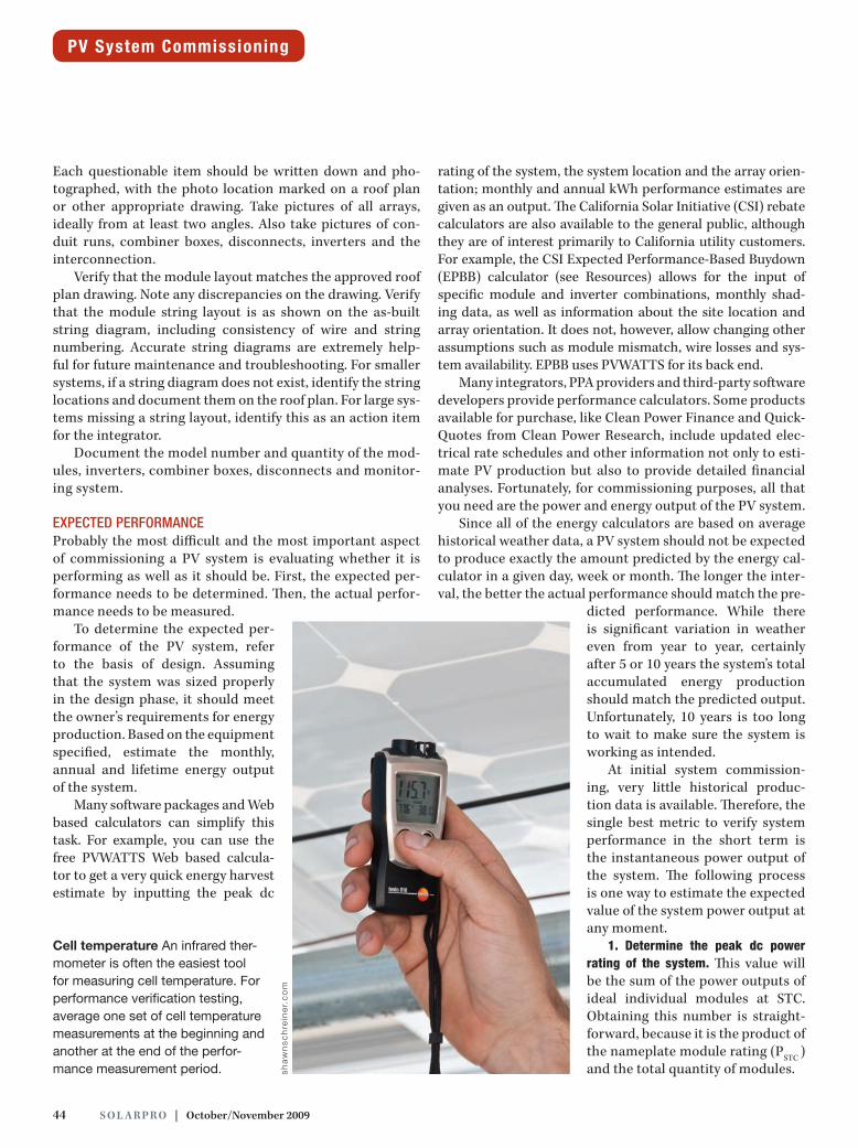
Cell temperature An infrared ther-mometer is often the easiest tool for measuring cell temperature. For performance verification testing, average one set of cell temperature measurements at the beginning and another at the end of the perfor-mance measurement period.
solarprofessional.com | S o l a r Pr o 45
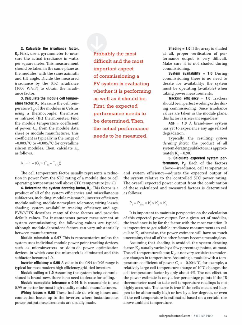
2. Calculate the irradiance factor, KI. First, use a pyranometer to mea-sure the actual irradiance in watts per square meter. This measurement should be taken in the same plane as the modules, with the same azimuth and tilt angle.Divide themeasuredirradiance by the STC irradiance (1000 W/m2) to obtain the irradi-ance factor.
3. Calculate the module cell temper-ature factor, KT. Measurethecelltem-perature TC of the modules in Celsius using a thermocouple, thermistor or infrared (IR) thermometer. Find the module temperature coefficient of power, CT, from the module data sheet or module manufacturer. This coefficient is typically in the range of −0.003/°C to −0.005/°C for crystalline silicon modules. Then, calculate KT as follows:
Kt = 1 + (ct × (tc − tStc))
The cell temperature factor usually represents a reduc-tion in power from the STC rating of a module due to cell operating temperature well above STC temperature (25°C).
4. Determine the system derating factor, KS. This factor is a product of all of the system efficiencies and miscellaneous subfactors, including: module mismatch, inverter efficiency, module soiling, module nameplate tolerance, wiring losses, shading, system availability, tracking efficiency and age. PVWATTS describes many of these factors and provides default values. For instantaneous power measurement at system commissioning, the following values are typical, although module-dependent factors can vary substantially between manufacturers:
Module mismatch = 0.97 This is representative unless the system uses individual module power point tracking devices, such as microinverters or dc-to-dc power optimization devices, in which case the mismatch is eliminated and this subfactor becomes 1.0.
Inverter efficiency = 0.96 A value in the 0.94 to 0.96 range is typical for most modern high efficiency grid-tied inverters.
Module soiling = 1.0 Assuming the system being commis-sioned is brand-new, there is no need to derate for soiling.
Module nameplate tolerance = 0.99 It is reasonable to use 0.99 or better for most high-quality module manufacturers.
Wiring losses = 0.98 These include dc wiring losses and connection losses up to the inverter, where instantaneous power output measurements are usually made.
Shading = 1.0 If the array is shaded at all, proper verification of per-formance output is very difficult. Make sure it is not shaded duringcommissioning.
System availability = 1.0 Duringcommissioning there is no need to derate for availability; the system must be operating (available) when taking power measurements.
Tracking efficiency = 1.0 Trackers should be in perfect working order dur-ing commissioning. Since irradiance values are taken in the module plane, this factor is irrelevant regardless.
Age = 1.0 A brand-new system has yet to experience any age related degradation.
Typically, the resulting system derating factor, the product of all system derating subfactors, is approxi-mately KS = 0.90.
5. Calculate expected system per-formance, PE. Each of the factorsabove—irradiance, cell temperature
and system efficiency—adjusts the expected output of the system relative to the controlled STC power rating. The overall expected power output from the combination of these calculated and measured factors is determined as follows:
pe = pStc × Ki × Kt × KS
It is important to maintain perspective on the calculation of this expected power output. For a given set of modules, the irradiance is by far the factor with the most variation. It is imperative to get reliable irradiance measurements to cal-culate KI; otherwise, the power estimate will have so much uncertainty that all of the other factors become meaningless.
Assuming that shading is avoided, the system derating factor, KS, usually varies by a few percentage points, at most. The cell temperature factor, KT, is not very sensitive to moder-ate changes in temperature. Assuming a module with a tem-perature coefficient of power CT = −0.004/°C, for example, a relatively large cell temperature change of 10°C changes the cell temperature factor by only about 4%. The net effect on the power estimate is only a few percentage points if the IR thermometer used to take cell temperature readings is not highly accurate. The same is true if the cells measured hap-pen to be abnormally high or low by a few degrees, or even if the cell temperature is estimated based on a certain rise above ambient temperature.
SProbably the most
difficult and the most
important aspect
of commissioning a
PV system is evaluating
whether it is performing
as well as it should be.
First, the expected
performance needs to
be determined. Then,
the actual performance
needs to be measured.

46 S o l a r Pr o | october/November 2009
The irradiance reading in the module plane, however, can easily vary from 400 W/m2 to 1200 W/m2. From the 800 W/m2 nominal terrestrial environment base value, irradiance in the plane of the array might change 50% in either direction. The effect of this range of irradiance on the net predicted power output is also +/− 50%. Clearly, it would be unac-ceptable to look up at the sky and guess “bright,” “overcast” or “hazy,” rather than taking an accurate in-plane irradi-ance measurement. On a residential system with as few asthree paralleled strings, an entire string could be discon-nected and the commissioning test might not catch it if the in-plane irradiance is not measured with precision.
performance measuremenTs The second half of performance verification is comparing the expected power output to the measured power output. After you have verified that all of the specified equipment was installed, you can measure and document the perfor-mance of that equipment and compare it to the expected values. Personal protective equipment is mandatory. Several tests are mandatory prior to inverter start-up. After start-up, you can capture measured power output and compare it to the expected performance.
Megger test each homerun. Homerun wiring should be tested with a megohm-meter before modules are connected. In fact,
depending on the type of racking and accessibility under the modules, often homerun wiring should be Megger testedbefore the modules are installed. If problems are found, the homerun wiring is completely accessible for examination and replacement. Also, after all of the homerun wiring checks out, both module-to-module connections and module-to- homerun connections can be made as the modules are placed, as long as the inverter ends of the homeruns are safely termi-natedandlockedout.EventhoughMeggertestingistypicallycarried out before the PV installation is complete and full com-missioning can occur, the test results should be documented as they are obtained to avoid the need to repeat testing later.
Measure Voc of each string. Open-circuit voltage can bemeasured only while the strings are independent of each other and before they are combined. For small string invert-ers, this may mean measuring Voc on the line side of the dc disconnect, with the dc disconnect open. For larger invert-ers, it likely means measuring Voc on the line side of the fuseholders in the combiner boxes, with the fuses removed. Oncethecombinerboxfusesareinsertedorthedcdiscon-nect is closed in a system with no combiner box, all of the strings are combined in parallel. Therefore, they will all mea-sure the same Voc, which is misleading when trying to verify individual strings. Verifying individual string Voc measure-ments is the quickest way to ensure that c o n t i n u e d o n pa g e 4 8
PV System Commissioning
Voltage measurements As evidenced by this open-circuit voltage measurement, the same personal protective equipment required for building the PV system is required during system commissioning. sh
aw
nsc
hre
ine
r.c
om
(2
)
Inverter start-up The sequence of steps required prior to inverter start-up includes line-to-line, line-to-neutral and line-to-ground measure-ments at the ac disconnect.
48 S o l a r Pr o | october/November 2009
all strings have the same number of modules and the correct polarity. After this is verified, replace the series fuses and close the fuseholders.
Inverter startup sequence. After you have completed all the visual inspections and confirmed the dc open-circuit string voltages, the system can be started up. Always follow the inverter manufacturer’s directions for initial startup. Typi-cally, the steps will include the following:
• Verifyallconnections.• Verifycorrectacvoltageattheac
disconnect.• Verifycorrectdcvoltageandpolarityat
the dc disconnect(s).• Closetheacdisconnect.• Verifycorrectacvoltageattheinverter
ac terminals.• Closethedcdisconnect(s).• Verifydcvoltageandpolarityatthe
inverter dc terminals.• Ifapplicable,switchtheinverter“ON.”• Waitfortheinvertertostepthrough
its internal startup sequence.• Oncetheinverterisrunning,waitabout
15 minutes for internal temperatures and power point tracking to stabilize.
Measure Imp for each string. Before paying much attention to the total inverter output, verify that each string is producing approximately the same amount of current. At the combiner box or another accessible location, use a dc clamp meter to measure the current in the ungrounded source circuit con-ductor of each string. If weather conditions are consistent during the testing and all strings are oriented with the same azimuth and tilt angle, the measured current values should be identical, or at least within about 0.1 A of each other. For systems with individual module monitoring, verify that all modules are producing the same power levels.
If one string has no current at all, check again to make sure both homeruns and all module leads are plugged in. If one string has lower current than the others, double-check to make sure that string is not partially shaded either by a distant tree, a nearby person or the commissioning agent’s notebook rest-ing on one of its modules. If no shading is present, measure the current on the grounded dc string conductor. If the current is different on the grounded conductor and the ungrounded con-ductor of the same string, a ground fault is likely carrying the difference in current. For larger central inverters, the ground fault current from a fraction of one string may not be enough to trip the detection circuitry or blow the fuse.
Measure ac power output. If measured current on all strings checks out, it is time to verify the inverter ac power output.
Using a clamp meter for current and a multi-meter for voltage, verify that the voltage, current and power displayed on the inverter match the measured values. Ideally, an independent power meter is used for this purpose, since it can also verify powerfactorandotherpowerqualitycomponents.Onceyouhave verified the inverter’s internal meter and display, you can use the power readings displayed on the inverter for all subse-quent power measurements and reporting.
performance VerificaTionAfter completing all of the commissioning tasks and per-formance measurements as described, it is time to measure power performance and compare this to predicted values. Only threemeasurements are necessary: cell temperature,irradiance and inverter ac output.
Of the three, cell temperature is the most stable, andac output is less sensitive to changes in temperature than changes in irradiance. Take one set of cell temperature mea-surements at the beginning and another at the end of the
PV System Commissioning
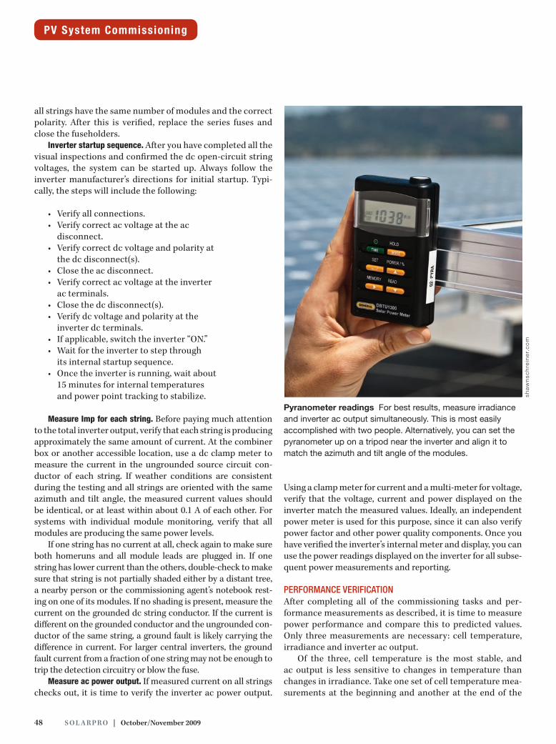
Pyranometer readings For best results, measure irradiance and inverter ac output simultaneously. This is most easily accomplished with two people. Alternatively, you can set the pyranometer up on a tripod near the inverter and align it to match the azimuth and tilt angle of the modules.
sha
wn
sch
rein
er.
co
m

solarprofessional.com | S o l a r Pr o 49
performance measurement period. The easiest tool to use for this purpose is an IR thermometer. Use this instrument to measure a few cell temperatures in dif-ferent places on a module and in a variety of locations throughout the array. Write down the average cell temperature in degrees Celsius.
Irradiance and inverter ac output must bemeasuredsimultaneously.Evenonarel-atively clear day, high clouds or haze can quickly change irradiance. Remember to look up at the sky periodically during test-ing. In one case, I was so focused on jump-ing back and forth between reading the inverter displays and getting the pyranometer lined up with the modules, I was surprised when I looked at the measure-ments I had written down over a period of about 2 minutes. Oneirradiancevaluewasmuchhigherthantheothertwo.Atfirst, I thought I must have written it down wrong or held the pyranometer at the wrong angle—pointing directly at the sun, for example—but then I noticed that the inverter output was also much higher. Finally, I looked up at the sky and noticed
that what had been a completely clear sky now had a couple of hard-edged cumulous clouds. I had just measured about a 10% increase in irradiance and production from the elusive edge-of-cloud effect.
With a full monitoring sys-tem or portable datalogger, 15 minutes’ worth of averaged irra-diance and ac output provide an excellent simultaneous reading. However, even with a simple $150 pyranometer and the inverter dis-play, you can obtain good results with the following method:
Find a good location to place the pyranometer so that it has exactly the same azimuth and tilt angle as the mod-ules. Ideally, the instrument has a square edge or bracket and can be clamped or held in place on the corner of a mod-ule toensurealignment.Makesure thepyranometerdoesnot shade the modules. Alternatively, set the pyranometer up on a tripod and carefully align it to match the azimuth and tilt angle of the modules. The tripod method requires
SIt is imperative to get
reliable irradiance
measurements;
otherwise, the power
estimate will have
so much uncertainty
that all other factors
become meaningless.
50 S o l a r Pr o | october/November 2009
a compass and inclinometer, but it is convenient if there is a sunny space to set up the tripod near the inverter.
Make sure that readings on thepyranometer and inverter can be taken within a few seconds of each other: either with two people and phones, radios or shouting; or with one person when inverters are near the pyranometer setup.
Write down the pyranometer reading in W/m2.
Write down the inverter power output in W or kW.
Repeat twice more, alternating back and forth between the pyra-nometer and the inverter, for a total of three alternated readings on each. Alternating three times between the two devices is a good approximation of “simultaneous” for this type of measurement.
If the variation between readings is small, less than 2%, for both inverter and pyranometer, move on to the next inverter and array. If the variation is large, start again and repeat the alternating readings until three consistent values are measured.
Finally, average the three irradiance readings and the three inverter power readings. These are the values to use when verifying performance.
After you have calculated the expected performance and measured the actual performance, a simple comparison helps you determine whether the system has been successfully commissioned. Depending on the certainty of the assumed
and measured factors, the actual perfor-mance should be within about 5% of the expected performance.
Some of the necessary measuring and reporting can be automated or accom-plished more easily by using an installed monitoring system, also known as a data acquisition system (DAS). Often,these systems report inverter ac power, irradiance and module cell temperature. Some even measure and report individ-ual string or module outputs. Duringinitial system commissioning, however, theDASmaynotbeproperlycalibratedor the network it relies on may not be set up. Further, the DAS reporting shouldbe verified by the on-site field measure-ments previously described.
case sTudY: 50 kWp commercial sYsTem, mulTiple inVerTers
PV array capacity: 50,310 W STC; 234 SunPower SPR-215-WHT-U modules Inverters: Six SunPower SPR-7000m and one SunPower SPR-4000m Array installation: Thirty-six of the modules are on a much steeper roof plane than the others and are dedicated to their own inverter.The system was originally commissioned, or partially
commissioned, just after construction was completed in the middle of the winter. There was some midafternoon shading on parts of the array that resulted in overall system perfor-mance of about 5% below the expected, c o n t i n u e d o n pa g e 5 2
PV System Commissioning
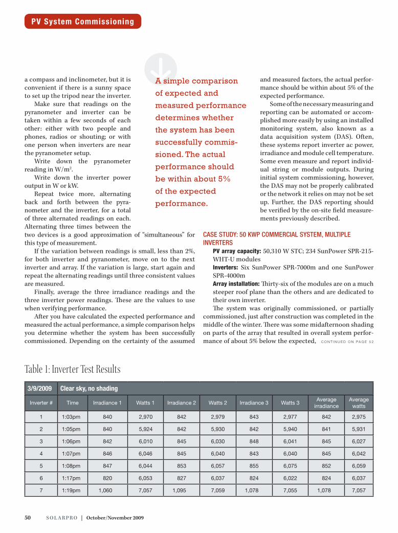
3/9/2009 Clear sky, no shading
Inverter # Time Irradiance 1 Watts 1 Irradiance 2 Watts 2 Irradiance 3 Watts 3Average
irradiance Average
watts
1 1:03pm 840 2,970 842 2,979 843 2,977 842 2,975
2 1:05pm 840 5,924 842 5,930 842 5,940 841 5,931
3 1:06pm 842 6,010 845 6,030 848 6,041 845 6,027
4 1:07pm 846 6,046 845 6,040 843 6,040 845 6,042
5 1:08pm 847 6,044 853 6,057 855 6,075 852 6,059
6 1:17pm 820 6,053 827 6,037 824 6,022 824 6,037
7 1:19pm 1,060 7,057 1,095 7,059 1,078 7,055 1,078 7,057
Table 1: Inverter Test Results
SA simple comparison
of expected and
measured performance
determines whether
the system has been
successfully commis-
sioned. The actual
performance should
be within about 5%
of the expected
performance.
52 S o l a r Pr o | october/November 2009
unshaded value. Because of the winter shad-ing, the system was recommissioned 3 months later, when the weather was clear and there was no shade. However, there was slight mod-ule soiling after 3 months (module soiling fac-torsetto0.99).Multipleirradianceandpowerreadings were taken for each inverter, with results summarized in Table 1 (p. 50).
Inverter 1 is the 4,000 W inverter with 18 modules, whereas the other six are 7,000 W inverters with 36 modules each. The 36 mod-ules on Inverter 7 are installed on a steeper roof, which is clearly a great angle for the early Marchsun,asseenbythehigherirradianceinthat module plane and higher production on that inverter. In addition, the 36 modules on the steeper roof plane receiving more irradi-ance were operating at a higher cell tempera-ture (42°C) than the other, lower-angle modules (35°C).
Temperature factor. The temperature factor, KT, is calcu-lated as follows: KT = 1 + (CT × (TC − TSTC)). In this case, the temperature coefficient of power, CT, is −0.38 %/°C , as sup-plied by the module manufacturer.
The measured cell temperature, CT, is 35°C for Inverters 1 through 6 and 42°C for Inverter 7. The STC reference tem-perature, TSTC, is 25°C. The temperature factor for Inverters 1 through 6 is therefore:
Kt = 1 + (ct × (tc − tStc))Kt = 1 + (−0.38 %/°c × (35°c − 25°c))Kt = 1 + (−0.38 %/°c × 10°c)Kt = 1 + (−0.038)Kt = 0.962
Using the same methodology, the temperature factor, KT, for Inverter 7 is calculated as 0.935.
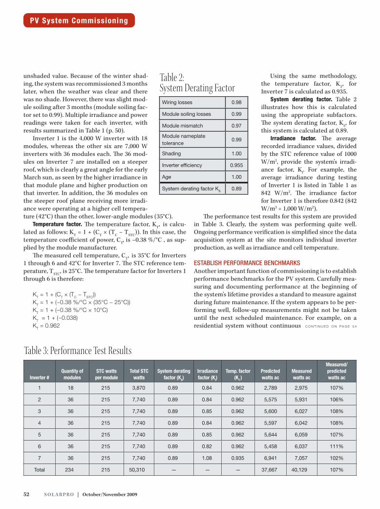
System derating factor. Table 2 illustrates how this is calculated using the appropriate subfactors. The system derating factor, KS, for this system is calculated at 0.89.
Irradiance factor. The average recorded irradiance values, divided by the STC reference value of 1000 W/m2, provide the system’s irradi-ance factor, KI. For example, the average irradiance during testing of Inverter 1 is listed in Table 1 as 842 W/m2. The irradiance factor for Inverter 1 is therefore 0.842 (842 W/m2 ÷ 1,000 W/m2).
The performance test results for this system are provided in Table 3. Clearly, the system was performing quite well. Ongoingperformanceverificationissimplifiedsincethedataacquisition system at the site monitors individual inverter production, as well as irradiance and cell temperature.
esTablish performance benchmarks Another important function of commissioning is to establish performance benchmarks for the PV system. Carefully mea-suring and documenting performance at the beginning of the system’s lifetime provides a standard to measure against during future maintenance. If the system appears to be per-forming well, follow-up measurements might not be taken until the next scheduled maintenance. For example, on a residential system without continuous c o n t i n u e d o n pa g e 5 4
PV System Commissioning
Inverter #Quantity of modules
STC watts per module
Total STC watts
System derating factor (KS)
Irradiance factor (KI)
Temp. factor(KT )
Predicted watts ac
Measured watts ac
Measured/predicted watts ac
1 18 215 3,870 0.89 0.84 0.962 2,789 2,975 107%
2 36 215 7,740 0.89 0.84 0.962 5,575 5,931 106%
3 36 215 7,740 0.89 0.85 0.962 5,600 6,027 108%
4 36 215 7,740 0.89 0.84 0.962 5,597 6,042 108%
5 36 215 7,740 0.89 0.85 0.962 5,644 6,059 107%
6 36 215 7,740 0.89 0.82 0.962 5,458 6,037 111%
7 36 215 7,740 0.89 1.08 0.935 6,941 7,057 102%
Total 234 215 50,310 — — — 37,667 40,129 107%
Table 3: Performance Test Results
Wiring losses 0.98
Module soiling losses 0.99
Module mismatch 0.97
Module nameplate tolerance
0.99
Shading 1.00
Inverter efficiency 0.955
Age 1.00
System derating factor KS 0.89
Table 2: System Derating Factor
54 S o l a r Pr o | october/November 2009
monitoring, the system owner can hang a clipboard next to the inverter and write down the inverter out-put at noon on the first sunny day of each month or the first sunny weekend day. These numbers will form a pattern over the years, and any drop in perfor-mancecanbeidentifiedandinvestigated.Ofcourse,the initial numbers must meet expected values. If the benchmark performance is unnecessarily low, the system may never meet its expected performance and no one will notice.
Similarly, after a year passes and system owners receive the first “true-up” bill from the utility to find they owe more than expected, they may point fingers at the integrator. The integrator need only repeat the measurements taken and documented the year before at commissioning. If these match, the sys-tem was undersized, or performance was overprom-ised from the beginning, or the customer has added loads that were not anticipated. Benchmark data is particularly useful in this scenario, especially if the customer formally accepted the results at the initial commissioning.
accepTance / cerTificaTionVarious parties have varying degrees of interest in accepting the PV system. In fact, one of the reasons to perform commissioning is to fulfill acceptance test requirements. Typical acceptance tests include:
DoesthePVsystemoperateinnormalgrid-tiemodewhen presented with normal operating conditions, such as in the presence of sun and utility power?
Is the ratio of measured system power output to pre-dicted power output of the system at least 0.95?
Most local jurisdictions will not check to makesure the PV system performs as designed. As with the NEC and most building codes, the AHJ’s main concern is that thesystemissafe.Often, thepermit issignedoffbeforethesystem is ever turned on.
Similarly, most utilities are satisfied if the system design passes the engineering review and the proper disconnects are observed at inspection.Occasionally, the utilitywill requirethat automatic shutdown of the inverter upon grid failure be demonstrated. But a utility is rarely concerned with the mea-sured power production values of the system.
The PV integrator installing the system should be the first to pay attention to the initial system production. From installers to systemdesigners to companyCEOs,pride intheir final product is linked to kilowatt-hour production. The integrator should not internally accept the installation until proper operation and production is verified.
Naturally, the system owner is the party with the most interest in accepting the newly commissioned PV system.
The owner will count on the system to produce the expected power for several decades. If the owner is a PPA provider, it usually requires very strict acceptance testing. Funding of the project, and the next project, is highly dependent on the power produced from the system. The original PPA owner may own the system for only 5 years, at which point it must be demonstrably in good working order so that the “fair market value” buyout price remains as high as possible.
TrainingAs part of the commissioning process, the PV integrator should train the owner on basic system operation. This training should include a physical walkthrough of the entire system, especially noting disconnect locations and procedures. Inverter operation should also be reviewed, including any display screens and status lights. Signifi-cant time should be dedicated to studying the monitoring system, if one is installed. The owner c o n t i n u e d o n pa g e 5 6
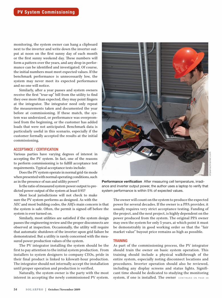
Performance verification After measuring cell temperature, irradi-ance and inverter output power, the author uses a laptop to verify that system performance is within 5% of expected values.
sha
wn
sch
rein
er.
co
m
PV System Commissioning
56 S o l a r Pr o | october/November 2009
should be clear on how to access the monitoring system display. The owner will need the URLs and passwords if the DASisWebbased,andwillneedtoknowhowtonavigatethat display, how often to look at it, what to look for and how to interpret alarms.
The integrator and owner should also review all system documentation,includingO&Mmanualsandwarranties.Ifa maintenance contract is included, the scope of the con-tract should be reviewed and the schedule and first mainte-nance visit should be agreed upon.
increasing emphasis on commissioningOther benefits to the owner of commissioned PV sys-tems come from acceptance, recognition and financial awards from third parties such as green-building certifi-cation organizations and rebate administration agencies. Forexample,oneoftheprerequisites fortheEnergyandAtmospherecreditcategoryforLeadershipinEnergyandEnvironmental Design (LEED) certification is the com-missioning of all building energy systems, including the PV system. Further, PV system commissioning explicitly requires performance verification. In other words, if the PV system performance is not verified, the building is not eligible for25%of the totalavailableLEEDpoints.Onceperformance is verified, the PV system itself can earn up
to three credit points towards certification. For many newcommercialbuildingswithPV,LEEDcertificationisa big deal. The PV commissioning agent needs to coordi-natewiththeLEEDbuildingcommissioningauthoritytoensure proper documentation.
Although rebate programs vary from state to state and even from city to city, most require an upfront prediction of system performance, upon which rebate dollar amounts are based. InCalifornia, theExpectedPerformance–Based Buydown rebate is based entirely on the expected perfor-mance, as the name implies. However, for larger systems—currently systems over 50 kW, but in 2010 everything over 30kW—therebateisentirelybasedonperformance.Energyproduction is metered and rebates are paid based on kWh production. Clearly, the system owner or other entity receiv-ing the rebate money has a large incentive to ensure that the system performs as expected. Similarly, the New Solar Homes Partnership rebate amount is based on expected performance, but actual payment is granted only after for-mal system acceptance. For acceptance, site temperature and irradiance measurements are required. The inverter- displayed power output must match the expected power out-put calculated for the measured irradiance and temperature values. In addition, several markets have recently adopted feed-in tariffs to stimulate PV installations.
The overall trend is clear. As performance based incen-tives and feed-in tariffs become more popular in the US, system owners will demand—and integrators will need to provide—excellent commissioning and performance verifi-cation services.
Special thanks to Sun Light & Power for arranging site access for project photography included with this article.
PV System Commissioning
blake gleason / sun light & power / berkeley, ca /
[email protected] / sunlightandpower.com
Resources:building commissioning association / bcxa.org (sample commissioning
requirements at: tinyurl.com/mrbw68)
clean power finance / cleanpowerfinance.com
clean power research / cleanpower.com
epbb rebate calculator / csi-epbb.com
leed / usgbc.org
pVWaTTs / nrel.gov/rredc/pVWaTTs
g C O N T A C T
X WEB ExClUSIVE Go to solarprofessional.com/webexclusive
for the followinG sample, downloadable documents: precommissioninG
checklist, commissioninG flowchart, performance verification form.
sha
wn
sch
rein
er.
co
m
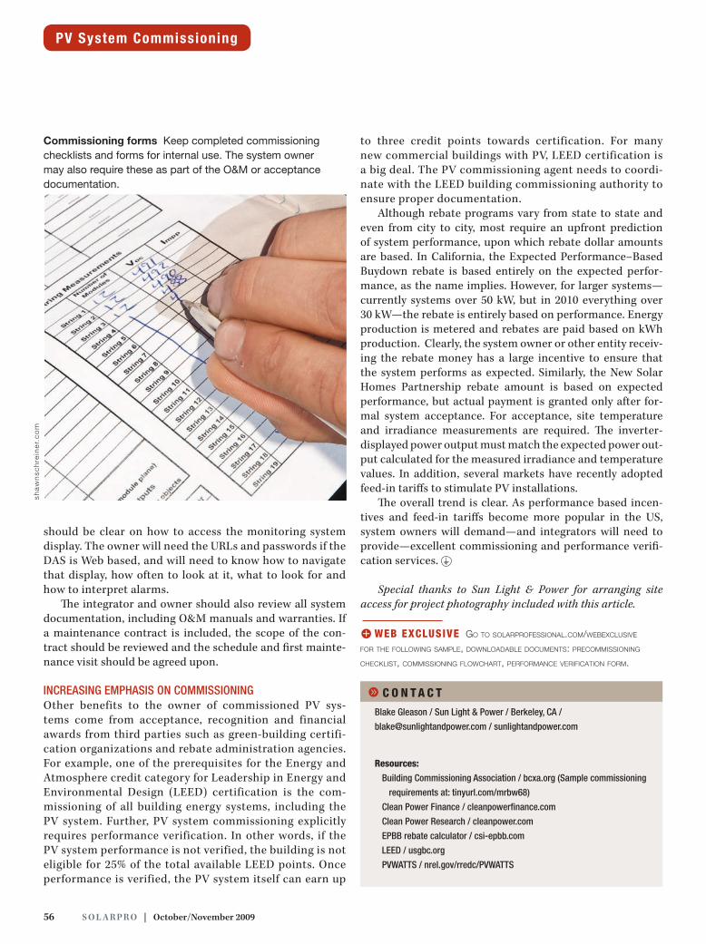
Commissioning forms Keep completed commissioning checklists and forms for internal use. The system owner may also require these as part of the O&M or acceptance documentation.