Embed Size (px)
Citation preview
INCINERATION PLANTS
A Bayer and LANXESScompany
Hazardous waste incinerationWastewater incinerationSewage sludge incineration
The thermal treatment of hazardous waste destroys harmful substances and recovers the energy contained in the waste for production processes at CHEMPARK.
INTRODUCTION
HAZARDOUS WASTE INCINERATION – Introduction
02
03
The thermal treatment of waste, sewage sludge, wastewa-ter and wastewater concentrates is a recognized method of waste management. It is particularly suitable for the safe and environmentally sound disposal of hazardous chemical waste. Incineration in this sense means the oxidation of organic waste to generate carbon dioxide, water and inorganic residues. Part of the latter can be recycled and the remainder can be disposed of safely. Over 300 companies from all over Europe and a small number of overseas customers commissioned CURRENTA Environment with disposing of their hazardous waste in 2007. These include Bayer’s subgroups and the companies located at CHEMPARK.
Waste management
The fundamental objective for CURRENTA Environment is the safe and environmentally sound disposal of hazardous waste. The energy released during this process is fed into the site grid in the form of steam. A further aim is to look for ways of recycling slag and ash. Inorganic salts and residues that cannot be reused after incineration are con-signed to the controlled hazardous waste landfill site. The incineration of hazardous waste ensures that• toxic organic substances are completely and definitively destroyed
• risks resulting from improper disposal of hazardous waste (i.e. tomorrow’s contaminated sites) are avoided
• the volume of waste is cut significantly
The thermal treatment of organic, toxic substances in hazardous waste incinerators destroys these substances and enables effective recovery of the energy present in the hazardous waste. CURRENTA Environment’s hazardous waste incineration plants convert this energy into steam that is fed into the site grid.
Hazardous waste from the chemical/pharmaceutical and chemical processing industries can be accepted in many different forms. In addition to bunkers for solid waste and loading arms for liquid and gaseous substances, there are also, for example, systems for receiving sludge of different consistencies and compositions. The many different kinds of hazardous waste that can be disposed of include:• production residues in solid, paste and liquid form• laboratory chemicals• chemically contaminated packaging• non-miscible, reactive liquids• highly halogenated and hot liquids• insecticides and pesticides• PCBs• concentrates
In 2007, customers from all over Europe and some over-seas companies commissioned CURRENTA Environment’s hazardous waste incinerators with the safe and environ-mentally sound disposal of their waste, accounting for over 25 percent of the incineration capacity available at that time.
Development of hazardous waste incineration plants
The first incinerator went into operation in 1957 in the Flit-tard section of the current CHEMPARK site. The experience gained was applied in the construction of incinerators 1 (year of construction 1967) and 2 (year of construction 1976) at the new Leverkusen-Bürrig Waste Management Center.
These rotary kiln waste incinerators are geared specifically to substances that are particularly difficult to dispose of. Development work took a long time as a result of problems with processes and materials. This work focused on opti-mizing burnout quality and flue gas cleaning.
Incinerator 1 underwent a general overhaul in 1989 and was equipped with the best flue gas cleaning technology available. In 1991/1992, incinerator 2 was also modernized to create a state-of-the-art plant. In 1995, the flue gas cleaning system was further upgraded to comply with the requirements of the German regulations governing emis-sions (17th BImSchV).
The incinerators must be able to reliably convert waste of different compositions and consistencies into substances that are not harmful to the environment. This requires highly efficient incineration processes, extremely effective downstream cleaning of flue gases and environmentally sound disposal of the slag, dust, salts and wastewater pro-duced. Additional requirements for cost-effective operation include high availability/low susceptibility to failure.
Rotary kiln incinerators proved ideal for disposing of all kinds of waste in liquid, paste and solid form. They are also suitable for the incineration of hazardous waste in all states of aggregation. Downstream from the incinerator is an afterburner chamber fired by liquid waste that ensures thorough mixing and complete burnout of flue gases.
Specific conditions relating to temperature and residence time, an excess of oxygen and high turbulence ensure complete mineralization of hazardous organic waste.
Step by step: An overview of plant components and processes for the incineration of hazardous waste
HAZARDOUS WASTE INCINERATORS (VA1 AND VA2)
CURRENTA Environment operates two hazardous waste in-cinerators at the Leverkusen site. Together with the landfill site, wastewater treatment plant and further incineration plants, these incinerators form part of the Leverkusen- Bürrig Waste Management Center’s disposal network.
Hazardous waste incinerators are made up of three pro-cess sections:• rotary kiln with afterburner chamber• waste heat boiler for steam generation• multi-stage flue gas cleaning
There is also an infrastructure for storing waste, distribu-ting it to the various plants and disposing of the residue and wastewater produced during incineration.
Feeding hazardous waste into the incineration chambers Combustible solids are extensively sorted in the bun-ker and collected in different sections. An orange-peel grapple loads incinerator 1’s rotary kiln via the furnace feed. Solid waste broken up into small pieces can be fed almost continuously into incinerator 2 using a feed device. The furnace feed and feed device protect the bunker from the rotary kiln by means of a sluice system.
Solid and non-pumpable waste is placed in the incinera-tors in closed containers. Pumpable liquid waste is trans-ported to the burners either from tank containers through separate pipes or directly from the tank farm. Whether waste is disposed of via separate pipes or the tank farm depends on its physical and chemical properties. Rotary kiln incinerator
The rotary kiln is a slightly inclined pipe with a diameter of 3.5 meters and a length of approximately 12 meters that is lined with fire-proof material. This inclination and rotation about the longitudinal axis transports waste through the rotary kiln in solid and paste form together with any waste melted by the high temperatures. The temperature at the end of the kiln is around 1,000 °C. The organic waste components are completely oxidized as they pass through the kiln. The inorganic waste components and metallic drum materials form a melt that runs off at the lower end into a slag remover filled with water where it solidifies and is discharged on a continuous basis. The vitreous slag is non-leachable and is suitable for landfilling. Because the rotary kiln is subject to high thermal, mechanical and chemical stresses, it must be regularly relined.
HAZARDOUS WASTE INCINERATION – Hazardous waste incinerators (VA1 and VA2)
Afterburner chamber
The afterburner chamber is a vertical cylinder that is also lined with fire-proof material. Burners charged with liquid waste ensure that the incineration temperature required by the authorities is maintained reached. The section above the burner level up to the top of the afterburner chamber is the afterburner area, which is large enough to comply with/exceed the statutory flue gas residence time (2 sec.). The slag running off from the walls of the afterburner chamber is collected at the bottom of the chamber and removed at regular intervals when the plant is not in operation.
Heat recovery
The hot flue gases leaving the afterburner chamber arrive at the boiler where their energy content is used to ge-nerate steam at an overpressure of approx. 41 bar and a temperature of around 350-380 °C. This steam is fed into the CHEMPARK grid as process steam.
Flue gas cleaning
During the subsequent multi-stage process, flue gases are cleaned to such an extent to ensure reliable compli-ance with the limits of the 17th BImSchV. Reliable compli-ance means being well within these limits under normal
operating conditions in order to leave a sufficient safety margin. The individual flue gas cleaning devices are de-scribed below.
Quencher – The first flue gas cleaning device is a scrubber operating in direct current mode in which flue gas and rinsing solution flow in the same direction. The quencher cools (quenches) the flue gas to its saturation temperature (approx. 70-80 °C). Acids and coarse dust are also removed.
Rotary scrubber (acidic) – In the acidic rotary scrubbers downstream from the quencher, the rinsing solution is fed onto centrifugal wheels, creating a fine film of liquid at right angles to the axis of the device – and thus at right angles to the flow of flue gas.
As this film flows through the device, the flue gas comes into close contact with the rinsing solution, removing further acidic flue gas components and fine dust.
Rotary scrubber (alkaline) – At this stage of flue gas clean-ing, the rinsing water is set to a neutral or slightly alkaline pH by adding sodium hydroxide solution. The scrubber re-moves sulfur oxides and further fine dust from the flue gas.
Electrostatic flue gas cleaning – Next comes the wet-wall electrostatic precipitator. This has a similar structure to a vertical tubular heat exchanger. The flue gas flows through
HAZARDOUS WASTE INCINERATION – Hazardous waste incinerators (VA1 and VA2)
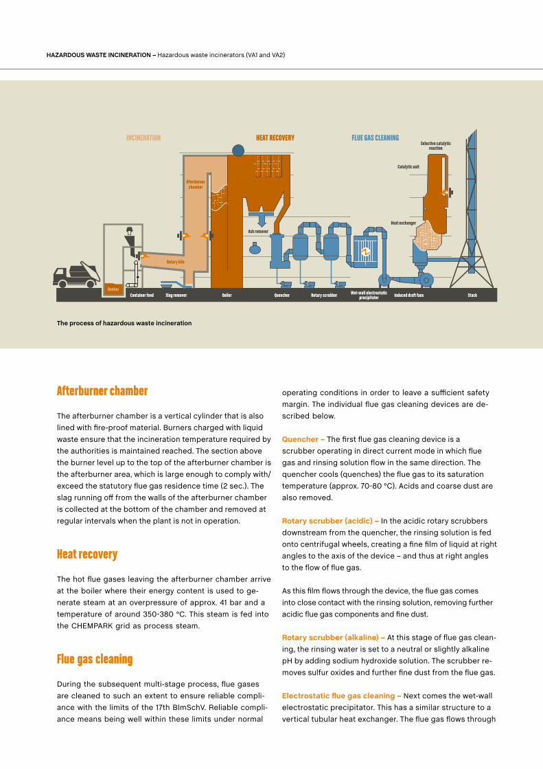
The process of hazardous waste incineration
Stack
Ash remover
Selective catalytic reaction
Induced draft fansRotary scrubber Wet-wall electrostatic precipitatorQuencherBoilerSlag remover
Rotary kiln
Afterburner chamber
Container feedBunker
Heat exchanger
Catalytic unit
INCINERATION HEAT RECOVERY FLUE GAS CLEANING
04
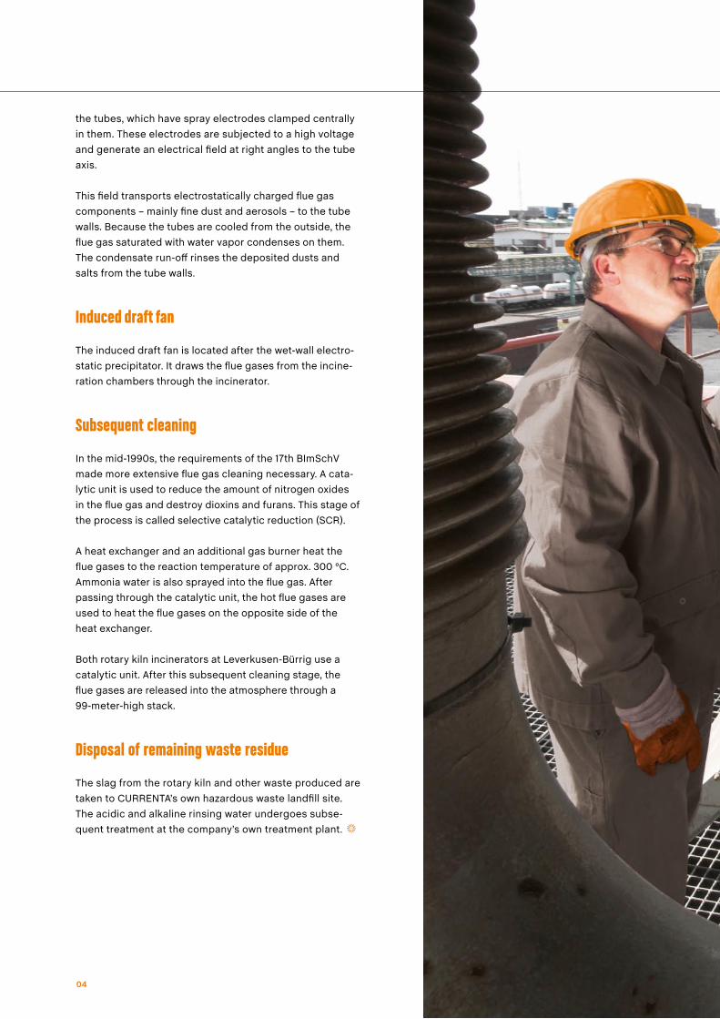
the tubes, which have spray electrodes clamped centrally in them. These electrodes are subjected to a high voltage and generate an electrical field at right angles to the tube axis.
This field transports electrostatically charged flue gas components – mainly fine dust and aerosols – to the tube walls. Because the tubes are cooled from the outside, the flue gas saturated with water vapor condenses on them. The condensate run-off rinses the deposited dusts and salts from the tube walls.
Induced draft fan
The induced draft fan is located after the wet-wall electro-static precipitator. It draws the flue gases from the incine-ration chambers through the incinerator.
Subsequent cleaning
In the mid-1990s, the requirements of the 17th BImSchV made more extensive flue gas cleaning necessary. A cata-lytic unit is used to reduce the amount of nitrogen oxides in the flue gas and destroy dioxins and furans. This stage of the process is called selective catalytic reduction (SCR).
A heat exchanger and an additional gas burner heat the flue gases to the reaction temperature of approx. 300 °C. Ammonia water is also sprayed into the flue gas. After passing through the catalytic unit, the hot flue gases are used to heat the flue gases on the opposite side of the heat exchanger.
Both rotary kiln incinerators at Leverkusen-Bürrig use a catalytic unit. After this subsequent cleaning stage, the flue gases are released into the atmosphere through a 99-meter-high stack.
Disposal of remaining waste residue
The slag from the rotary kiln and other waste produced are taken to CURRENTA’s own hazardous waste landfill site. The acidic and alkaline rinsing water undergoes subse-quent treatment at the company’s own treatment plant.
05
Step by step: An overview of plant components and processes for the incineration of wastewater
WASTEWATER INCINERATOR
06
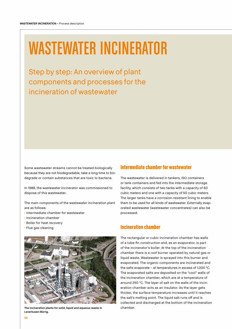
Some wastewater streams cannot be treated biologically because they are not biodegradable, take a long time to bio-degrade or contain substances that are toxic to bacteria.
In 1988, the wastewater incinerator was commissioned to dispose of this wastewater.
The main components of the wastewater incineration plant are as follows:• Intermediate chamber for wastewater• Incineration chamber• Boiler for heat recovery• Flue gas cleaning
Intermediate chamber for wastewater The wastewater is delivered in tankers, ISO containers or tank containers and fed into the intermediate storage facility, which consists of two tanks with a capacity of 60 cubic meters and one with a capacity of 50 cubic meters. The larger tanks have a corrosion-resistant lining to enable them to be used for all kinds of wastewater. Externally evap-orated wastewater (wastewater concentrates) can also be processed. Incineration chamber The rectangular or cubic incineration chamber has walls of a tube-fin construction and, as an evaporator, is part of the incinerator’s boiler. At the top of the incineration chamber there is a roof burner operated by natural gas or liquid waste. Wastewater is sprayed into this burner and evaporated. The organic components are incinerated and the salts evaporate – at temperatures in excess of 1,000 °C. The evaporated salts are deposited on the “cool” walls of the incineration chamber, which are at a temperature of around 250 °C. The layer of salt on the walls of the incin-eration chamber acts as an insulator. As the layer gets thicker, the surface temperature increases until it reaches the salt’s melting point. The liquid salt runs off and is collected and discharged at the bottom of the incineration chamber.
WASTEWATER INCINERATION – Process description
The incineration plants for solid, liquid and aqueous waste in Leverkusen-Bürrig.
05
Heat recovery
The hot flue gases leaving the incineration chamber arrive at the boiler where their energy content is used to ge-nerate steam at an overpressure of approx. 41 bar and a temperature of around 350-380 °C. This steam is fed into the CHEMPARK grid as process steam.
Flue gas cleaning
During the subsequent multi-stage process, flue gases are cleaned to such an extent to ensure reliable compli-ance with the limits of the 17th BImSchV. Reliable compli-ance means being well within these limits under normal operating conditions in order to leave a sufficient safety margin.
The individual flue gas cleaning devices are described below.
Quencher – The first flue gas cleaning device is the quen-cher, a scrubber operating in direct current mode, which means that the flue gas and rinsing solution flow in the same direction.
The quencher cools (quenches) the flue gas to its satura-tion temperature (approx. 70-80 °C). Acids and coarse salt dust are also removed.
Jet scrubber (alkaline) – After the quencher comes a jet scrubber with rinsing water set to a neutral or slightly al-kaline pH by adding sodium hydroxide solution. This mainly removes sulfur oxides and dust.
Electrostatic flue gas cleaning – After the alkaline jet scrub-ber comes the wet-wall electrostatic precipitation. This has a similar structure to a vertical tubular heat exchanger. The flue gas flows through the tubes, which have spray electrodes clamped centrally in them. These electrodes are subjected to a high voltage and generate an electrical field at right angles to the tube axis. This field transports electrostatically charged flue gas components – mainly fine dust and aerosols – to the tube walls. Because the tubes are cooled from the outside, the flue gas saturated with water vapor condenses on them. The condensate run-off rinses the deposited dusts and salts from the tube walls.
The wastewater incinerator’s wet-wall electrostatic precipi-tator has two depositing fields.
Induced draft fan
The induced draft fan is located after the wet-wall elec-trostatic precipitator. It draws the flue gases from the in- cineration chamber through the incinerator. The flue gases are released into the atmosphere through the incineration plant‘s stack.
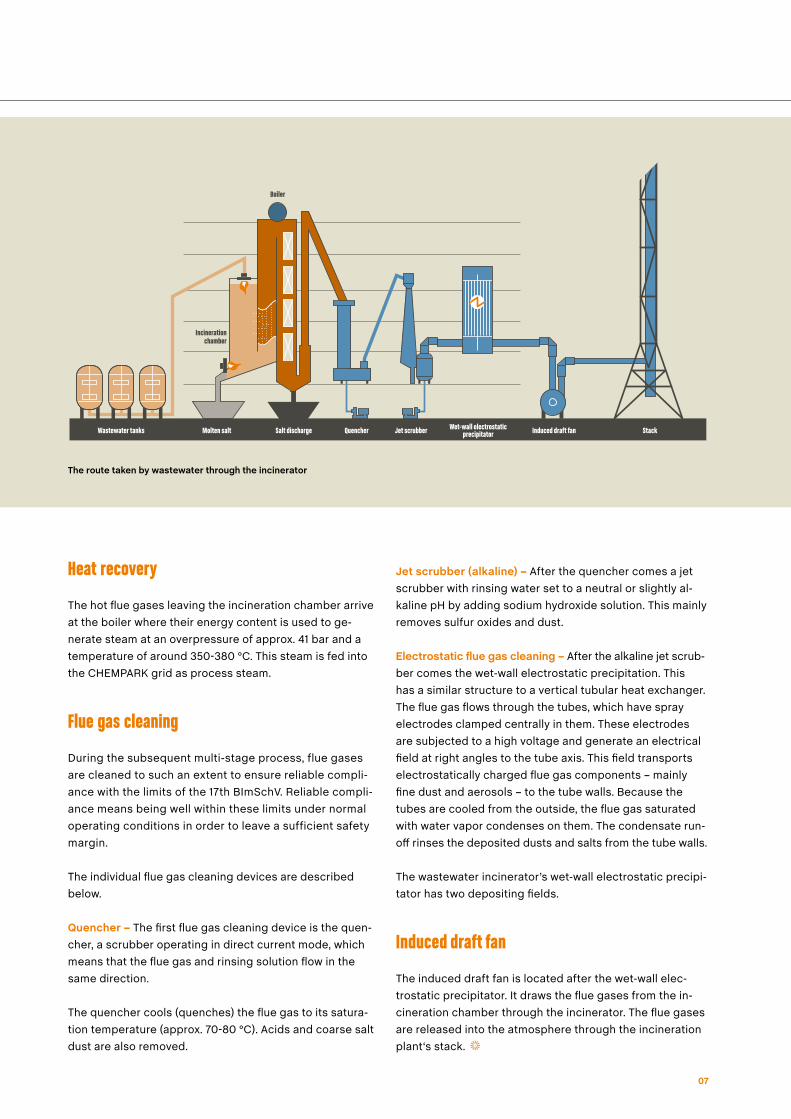
The route taken by wastewater through the incinerator
07
Wastewater tanks Molten salt Salt discharge Quencher Jet scrubber Induced draft fan StackWet-wall electrostatic precipitator
Boiler
Incinerationchamber
Step by step: An overview of plant components and processes for the incineration of sewage sludge
SEWAGE SLUDGE INCINERATION
08
The sewage sludge incinerator was commissioned in 1988 to incinerate the approximately 60,000 metric tons of sewage sludge produced by the community wastewater treatment plant at the Leverkusen-Bürrig Waste Manage-ment Center. Improved processes in the production units reduce the wastewater load and, together with the opti-mization of treatment processes, help significantly cut the annual levels of sewage sludge.
The sewage sludge incinerator capacity freed up in this way can be used for the thermal treatment of other types of sludge. Additional external sewage, industrial sludge of different consistencies and waste similar to sewage sludge with an energy content of up to 20 are also accepted for incineration.
The main components of the sewage sludge incinerator are as follows:• Multiple-hearth furnace• Afterburner chamber• Boiler for heat recovery• Flue gas cleaning
Multiple-hearth furnace
The multiple-hearth furnace is a cylindrical unit eight meters in diameter and twelve meters high with an internal lining. The inside is divided into eight sections by masonry
partitions. A (hollow) shaft runs along the axis of the vessel and stirring arms are attached in each hearth. The sewage sludge is fed into the multiple-hearth furnace at the outer edge and falls into the top hearth. This hearth’s stirring arms transport the sludge out of the hearth and on to the next hearth through discharge orifices. The sewage sludge winds its way through all the hearths in this way.
The top three hearths constitute the drying zone where water is evaporated from the sewage sludge. The organic components in the sewage sludge are incinerated in the following two hearths. The three hearths at the bottom are used to cool the ash with counterflowing incineration air. This ash is then discharged. The temperatures in the incineration zone reach up to 1,000 °C.
There is a booster chamber on the side of the sixth hearth. This is operated if the sewage sludge does not burn of its own accord.
Afterburner chamber
The flue gases from the multiple-hearth furnace and the exhaust vapors, i.e. evaporated water from the drying zone, are burnt off in the afterburner chamber with the addition of liquid waste.
SEWAGE SLUDGE INCINERATION – Process description
MJkg
05
Heat recovery
The hot flue gases leaving the afterburner chamber arrive at the boiler where their energy content is used to gen-erate steam at an overpressure of approx. 41 bar and a temperature of around 350-380 °C. This steam is fed into the CHEMPARK grid as process steam.
Flue gas cleaning
Quencher – The first flue gas cleaning device is the quen-cher, a scrubber operating in direct current mode, which means that the flue gas and rinsing solution flow in the same direction. The quencher cools (quenches) the flue gas to its saturation temperature (approx. 70-80 °C). Acids, heavy metals and coarse dust are also removed.
Rotary atomizing scrubber (acidic) – The remainder of the acids and heavy metals and further dust are removed in the highly effective acidic rotary atomizing scrubber.
Jet scrubber (alkaline) – After the rotary scrubber comes a jet scrubber with rinsing water set to a neutral or slightly al-kaline pH by adding sodium hydroxide solution. This mainly removes sulfur oxides.
Entrained-flow reactor – After the jet washer, the flue gas is heated back up to 160 °C. A solid adsorbent is then intro-
duced into the flue gas. The remaining flue gas components, such as heavy metals (Hg), are bound adsorptively to this. The adsorbent is separated off again in a downstream fabric filter.
Reduction of nitrogen oxides – A selective non-catalytic reaction (SNCR) is used to reduce the amount of nitrogen oxides in the flue gas. Ammonia water is sprayed into the flue gas underneath the afterburner chamber at approximately 1,030 °C (afterburning). Ammonia reduces the amount of nitrogen oxides in this temperature range.
Induced draft fan
The induced draft fan is located after the fabric filter. It draws the flue gases from the multiple-hearth furnace through the incinerator. The flue gases are released into the atmosphere through the incineration plant‘s stack.
09
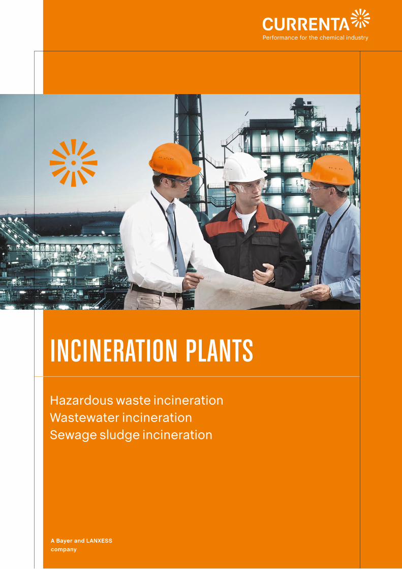
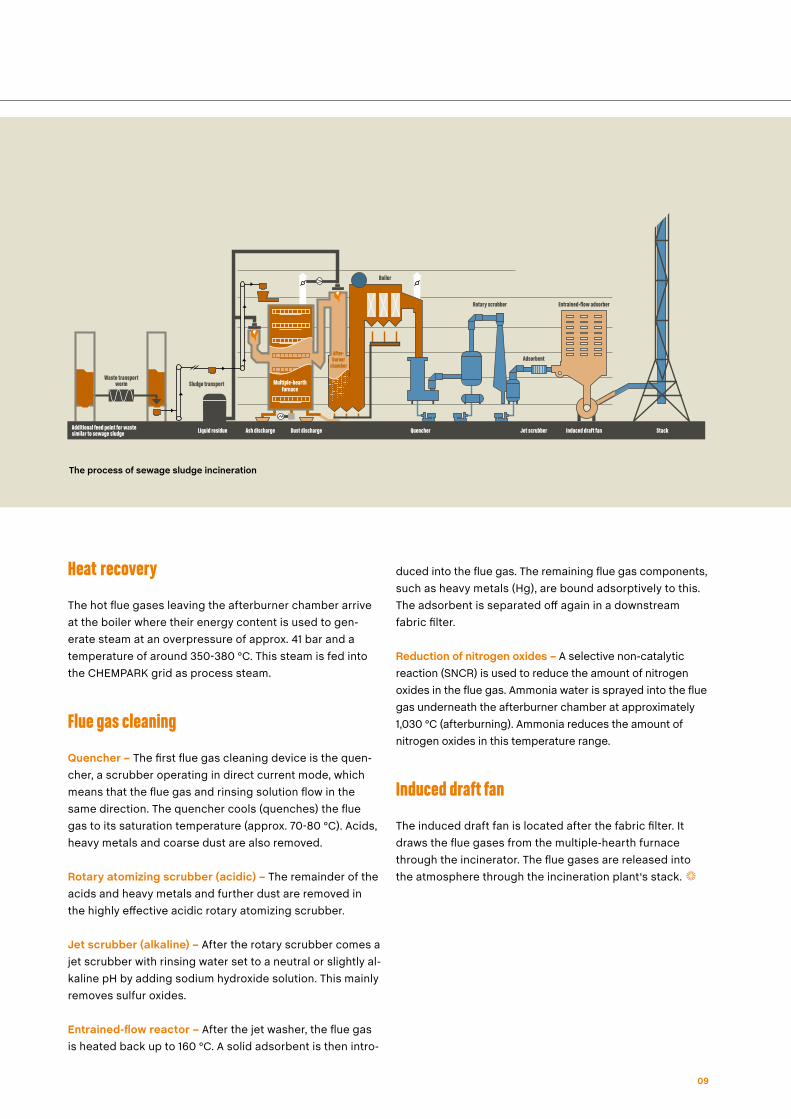
The process of sewage sludge incineration
KaminLiquid residue Ash discharge Dust discharge Quencher Jet scrubber Induced draft fan StackAdditional feed point for waste similar to sewage sludge
Boiler
Rotary scrubber Entrained-flow adsorber
Adsorbent
Multiple-hearthfurnace
After-burner
chamber
Sludge transportWaste transport
worm
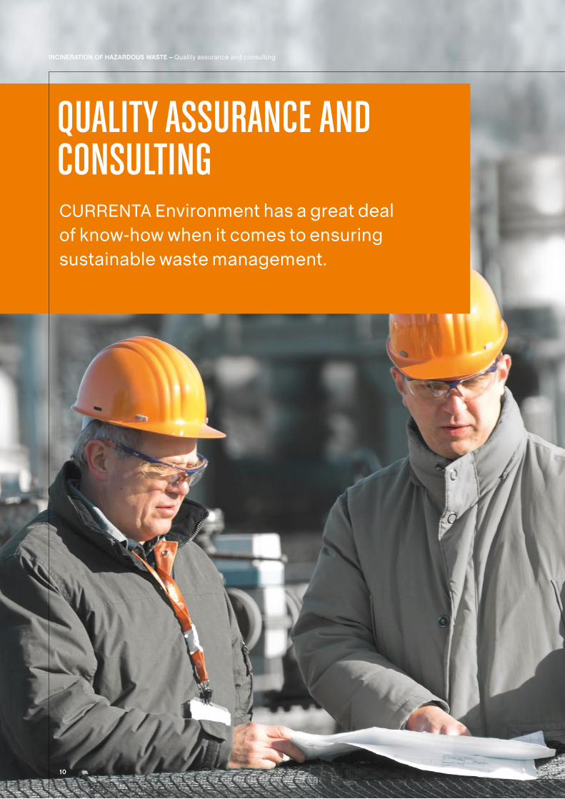
CURRENTA Environment has a great deal of know-how when it comes to ensuring sustainable waste management.
QUALITY ASSURANCE AND CONSULTING
10
INCINERATION OF HAZARDOUS WASTE – Quality assurance and consulting
11
Waste recording and waste logistics
Preparatory waste recording and waste logistics are an integral part of waste management. The best possible physical and chemical pre-treatment is established in consultation with the customer and it is decided, for ex-ample, whether incineration or landfill is the most suitable disposal method. This decision is based on information relating to• the quantity of waste and the frequency of delivery• the form the waste is supplied in• health and safety measures for handling the waste• chemical and physical properties• ignition temperature, flashpoint, calorific value, reactivity and critical components
Based on this information, CURRENTA Environment pre-pares all the relevant documents and obtains the neces-sary permits. Quality assurance for waste management is
performed by means of accompanying analyses, the evalu-ation of shipping documents and use of an internal quality management system that covers all key operations.
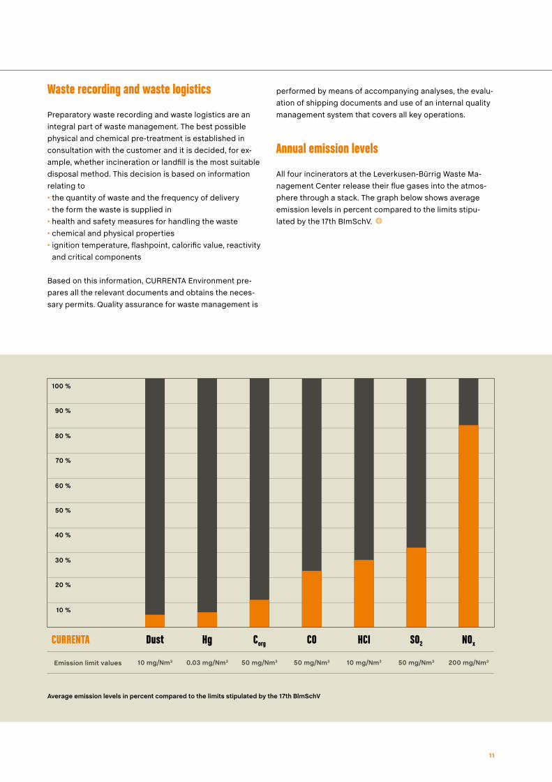
Annual emission levels
All four incinerators at the Leverkusen-Bürrig Waste Ma-nagement Center release their flue gases into the atmos-phere through a stack. The graph below shows average emission levels in percent compared to the limits stipu-lated by the 17th BImSchV.
Average emission levels in percent compared to the limits stipulated by the 17th BlmSchV
10 mg/Nm350 mg/Nm350 mg/Nm30.03 mg/Nm310 mg/Nm3 50 mg/Nm3Emission limit values
10 %
20 %
30 %
40 %
50 %
60 %
70 %
80 %
90 %
100 %
200 mg/Nm3
HCICOCorgHgDust SO2 N0xCURRENTA
Published by
Currenta GmbH & Co. OHG
51368 Leverkusen
Germany
www.currenta.com
As at: March 2010