Embed Size (px)
Citation preview
Planning
HYDRAULIC DRIVE 1000 lb. (453 Kg)
AMERICA’S MOST CUSTOMIZABLE ELEVATOR
Guide
INCLINATOR ELEVETTE®
PN 67210815 Rev J

2 HYDRAULIC DRIVE - 1000 PLANNING GUIDE
PN 67210815 Rev J
This page intentionally left blank.
HYDRAULIC DRIVE – 1000 PLANNING GUIDE 3
PN 67210815 Rev J
Table of Contents
Introduction .......................................................................................... 4
Planning Steps for an Inclinator Elevette ............................................ 5
Hoistway Layout .................................................................................. 6
Hoistway Construction ....................................................................... 11
Flush Mount Door Frame Kit ............................................................. 12
Alternate Hoistway Construction ....................................................... 13
Technical Specifications .................................................................... 13
Hoistway Specifications ..................................................................... 14
Hoistway Elevation ............................................................................ 15
Machine Room Specifications ........................................................... 16
Hall Call Stations ............................................................................... 17
UC601 Cable Lengths and Components ........................................... 19
Warranty ............................................................................................ 20

4 HYDRAULIC DRIVE - 1000 PLANNING GUIDE
PN 67210815 Rev J
Introduction
It started over 90 years ago with a passion to help an ailing friend access his multi-level home. Now, almost a century later, the Inclinator craftsmanship can be found in more North American homes today than any other brand. We want to use our heritage of service to enhance each stage of your building or remodeling experience and to help you create a uniquely personalized elevator for your home.
Of all the stages, none is quite as exciting as the initial design phase. It’s where you begin to imagine the possibilities of something that’s uniquely yours. A home is personalized by the components you choose to fit your needs.
Our Planning Guide is designed to simplify and assist architects, contractors, home owners and dealers in planning for a home elevator that meets or exceeds the requirements of ASME A17.1-2016 and CSA B44-13.
We recommend you contact an authorized dealer in the area where the elevator will be installed. They will be knowledgeable about local codes and restrictions. Become familiar with all requirements governing the installation and use of elevators. It is extremely important for you to know and adhere to all regulations concerning installation.
This Planning Guide provides nominal dimensions and specifications useful for the initial planning of an elevator project. Before beginning actual construction, be sure to contact a local authorized dealer and obtain approval drawings customized with specifications and dimensions for your specific project. Call 1-800-343-9007 to find a local dealer or visit our website, www.inclinator.com. Inclinator hydraulic elevators manufactured and installed under the proper parameters are warranted for 3 years. We assume no liability for equipment not installed in compliance with national, state, and local codes.
HYDRAULIC DRIVE – 1000 PLANNING GUIDE 5
PN 67210815 Rev J
Planning Steps for an Inclinator Elevette
1. Locate local dealer and together determine the following:
a. Select a drive system, cab type and design specifications
b. Address national, state and local code requirements
c. Determine installation parameters of site
2. Obtain approval drawings before building hoistway, doorways,
pit and any other construction related to the elevator
3. Coordinate with dealer to order and install the elevator
6 HYDRAULIC DRIVE - 1000 PLANNING GUIDE
PN 67210815 Rev J
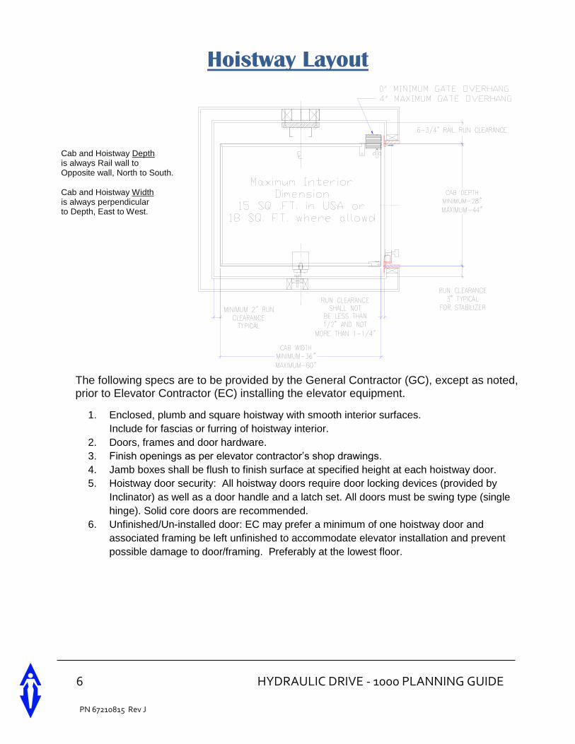
Hoistway Layout
The following specs are to be provided by the General Contractor (GC), except as noted, prior to Elevator Contractor (EC) installing the elevator equipment.
1. Enclosed, plumb and square hoistway with smooth interior surfaces.
Include for fascias or furring of hoistway interior.
2. Doors, frames and door hardware.
3. Finish openings as per elevator contractor’s shop drawings.
4. Jamb boxes shall be flush to finish surface at specified height at each hoistway door.
5. Hoistway door security: All hoistway doors require door locking devices (provided by
Inclinator) as well as a door handle and a latch set. All doors must be swing type (single
hinge). Solid core doors are recommended.
6. Unfinished/Un-installed door: EC may prefer a minimum of one hoistway door and
associated framing be left unfinished to accommodate elevator installation and prevent
possible damage to door/framing. Preferably at the lowest floor.
Cab and Hoistway Depth is always Rail wall to Opposite wall, North to South. Cab and Hoistway Width is always perpendicular to Depth, East to West.
HYDRAULIC DRIVE – 1000 PLANNING GUIDE 7
PN 67210815 Rev J
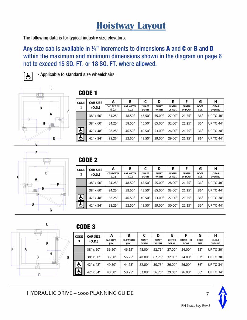
Hoistway Layout
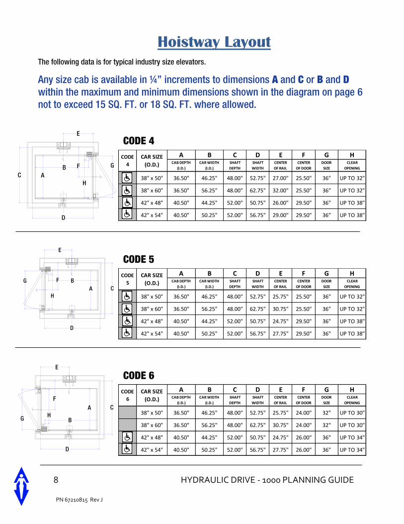
The following data is for typical industry size elevators.
Any size cab is available in ¼” increments to dimensions A and C or B and D within the maximum and minimum dimensions shown in the diagram on page 6 not to exceed 15 SQ. FT. or 18 SQ. FT. where allowed.
- Applicable to standard size wheelchairs
CODE 1
CODE 2
CODE 3
E
C
D
B
FH
A
G
A B C D E F G HCA B DEP TH
( I.D.)
CAR WIDTH
(I.D.)
SHAFT
DEPTH
SHAFT
WIDTH
CENTER
OF RAIL
CENTER
OF DOOR
DOOR
SIZE
CLEAR
OPENING
38" x 50" 34.25" 48.50" 45.50" 55.00" 27.00" 21.25" 36" UP TO 40"
38" x 60" 34.25" 58.50" 45.50" 65.00" 32.00" 21.25" 36" UP TO 44"
42" x 48" 38.25" 46.50" 49.50" 53.00" 26.00" 21.25" 36" UP TO 38"
42" x 54" 38.25" 52.50" 49.50" 59.00" 29.00" 21.25" 36" UP TO 44"
CODE
1
CAR SIZE
(O.D.)
A B C D E F G HCAB DEPTH
(I.D.)
CAR WIDTH
(I.D.)
SHAFT
DEPTH
SHAFT
WIDTH
CENTER
OF RAIL
CENTER
OF DOOR
DOOR
SIZE
CLEAR
OPENING
38" x 50" 34.25" 48.50" 45.50" 55.00" 28.00" 21.25" 36" UP TO 40"
38" x 60" 34.25" 58.50" 45.50" 65.00" 33.00" 21.25" 36" UP TO 44"
42" x 48" 38.25" 46.50" 49.50" 53.00" 27.00" 21.25" 36" UP TO 38"
42" x 54" 38.25" 52.50" 49.50" 59.00" 30.00" 21.25" 36" UP TO 44"
CODE
2
CAR SIZE
(O.D.)
E
C
D
B
FH
A
G
FC
D
HB
A
E
G
A B C D E F G HCAB DEPTH
(I.D.)
CAR WIDTH
(I.D.)
SHAFT
DEPTH
SHAFT
WIDTH
CENTER
OF RAIL
CENTER OF
DOOR
DOOR
SIZE
CLEAR
OPENING
38" x 50" 36.50" 46.25" 48.00" 52.75" 27.00" 24.00" 32" UP TO 30"
38" x 60" 36.50" 56.25" 48.00" 62.75" 32.00" 24.00" 32" UP TO 30"
42" x 48" 40.50" 44.25" 52.00" 50.75" 26.00" 26.00" 36" UP TO 34"
42" x 54" 40.50" 50.25" 52.00" 56.75" 29.00" 26.00" 36" UP TO 34"
CODE
3
CAR SIZE
(O.D.)
8 HYDRAULIC DRIVE - 1000 PLANNING GUIDE
PN 67210815 Rev J
Hoistway Layout
The following data is for typical industry size elevators.
Any size cab is available in ¼” increments to dimensions A and C or B and D within the maximum and minimum dimensions shown in the diagram on page 6 not to exceed 15 SQ. FT. or 18 SQ. FT. where allowed.
CODE 4
CODE 5
CODE 6
A B C D E F G HCAB DEPTH
(I.D.)
CAR WIDTH
(I.D.)
SHAFT
DEPTH
SHAFT
WIDTH
CENTER
OF RAIL
CENTER
OF DOOR
DOOR
SIZE
CLEAR
OPENING
38" x 50" 36.50" 46.25" 48.00" 52.75" 27.00" 25.50" 36" UP TO 32"
38" x 60" 36.50" 56.25" 48.00" 62.75" 32.00" 25.50" 36" UP TO 32"
42" x 48" 40.50" 44.25" 52.00" 50.75" 26.00" 29.50" 36" UP TO 38"
42" x 54" 40.50" 50.25" 52.00" 56.75" 29.00" 29.50" 36" UP TO 38"
CAR SIZE
(O.D.)
CODE
4F
E
C
D
H
BA
G
FC
D
H
BA
E
GA B C D E F G H
CAB DEPTH
(I.D.)
CAR WIDTH
(I.D.)
SHAFT
DEPTH
SHAFT
WIDTH
CENTER
OF RAIL
CENTER
OF DOOR
DOOR
SIZE
CLEAR
OPENING
38" x 50" 36.50" 46.25" 48.00" 52.75" 25.75" 25.50" 36" UP TO 32"
38" x 60" 36.50" 56.25" 48.00" 62.75" 30.75" 25.50" 36" UP TO 32"
42" x 48" 40.50" 44.25" 52.00" 50.75" 24.75" 29.50" 36" UP TO 38"
42" x 54" 40.50" 50.25" 52.00" 56.75" 27.75" 29.50" 36" UP TO 38"
CODE
5
CAR SIZE
(O.D.)
A B C D E F G HCAB DEPTH
(I.D.)
CAR WIDTH
(I.D.)
SHAFT
DEPTH
SHAFT
WIDTH
CENTER
OF RAIL
CENTER
OF DOOR
DOOR
SIZE
CLEAR
OPENING
38" x 50" 36.50" 46.25" 48.00" 52.75" 25.75" 24.00" 32" UP TO 30"
38" x 60" 36.50" 56.25" 48.00" 62.75" 30.75" 24.00" 32" UP TO 30"
42" x 48" 40.50" 44.25" 52.00" 50.75" 24.75" 26.00" 36" UP TO 34"
42" x 54" 40.50" 50.25" 52.00" 56.75" 27.75" 26.00" 36" UP TO 34"
CODE
6
CAR SIZE
(O.D.)FC
D
HB
A
E
G
HYDRAULIC DRIVE – 1000 PLANNING GUIDE 9
PN 67210815 Rev J
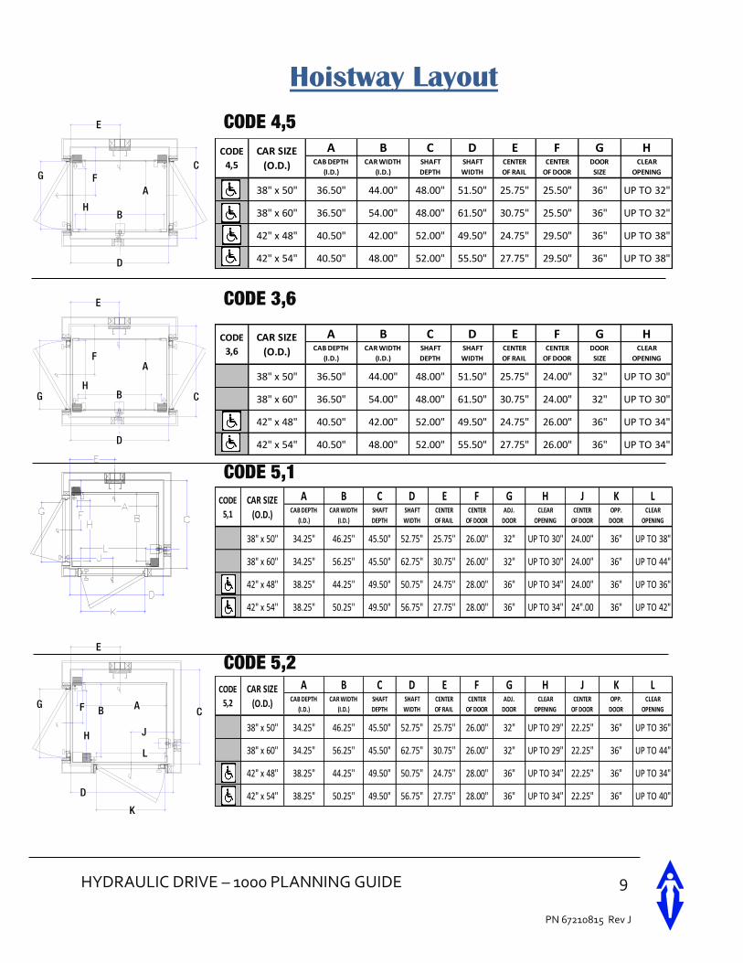
Hoistway Layout
CODE 4,5
CODE 3,6
CODE 5,1
CODE 5,2
A B C D E F G HCAB DEPTH
(I.D.)
CAR WIDTH
(I.D.)
SHAFT
DEPTH
SHAFT
WIDTH
CENTER
OF RAIL
CENTER
OF DOOR
DOOR
SIZE
CLEAR
OPENING
38" x 50" 36.50" 44.00" 48.00" 51.50" 25.75" 25.50" 36" UP TO 32"
38" x 60" 36.50" 54.00" 48.00" 61.50" 30.75" 25.50" 36" UP TO 32"
42" x 48" 40.50" 42.00" 52.00" 49.50" 24.75" 29.50" 36" UP TO 38"
42" x 54" 40.50" 48.00" 52.00" 55.50" 27.75" 29.50" 36" UP TO 38"
CODE
4,5
CAR SIZE
(O.D.)
A B C D E F G HCAB DEPTH
(I.D.)
CAR WIDTH
(I.D.)
SHAFT
DEPTH
SHAFT
WIDTH
CENTER
OF RAIL
CENTER
OF DOOR
DOOR
SIZE
CLEAR
OPENING
38" x 50" 36.50" 44.00" 48.00" 51.50" 25.75" 24.00" 32" UP TO 30"
38" x 60" 36.50" 54.00" 48.00" 61.50" 30.75" 24.00" 32" UP TO 30"
42" x 48" 40.50" 42.00" 52.00" 49.50" 24.75" 26.00" 36" UP TO 34"
42" x 54" 40.50" 48.00" 52.00" 55.50" 27.75" 26.00" 36" UP TO 34"
CODE
3,6
CAR SIZE
(O.D.)
A B C D E F G H J K LCAB DEPTH
(I.D.)
CAR WIDTH
(I.D.)
SHAFT
DEPTH
SHAFT
WIDTH
CENTER
OF RAIL
CENTER
OF DOOR
ADJ.
DOOR
CLEAR
OPENING
CENTER
OF DOOR
OPP.
DOOR
CLEAR
OPENING
38" x 50" 34.25" 46.25" 45.50" 52.75" 25.75" 26.00" 32" UP TO 30" 24.00" 36" UP TO 38"
38" x 60" 34.25" 56.25" 45.50" 62.75" 30.75" 26.00" 32" UP TO 30" 24.00" 36" UP TO 44"
42" x 48" 38.25" 44.25" 49.50" 50.75" 24.75" 28.00" 36" UP TO 34" 24.00" 36" UP TO 36"
42" x 54" 38.25" 50.25" 49.50" 56.75" 27.75" 28.00" 36" UP TO 34" 24".00 36" UP TO 42"
CODE
5,1
CAR SIZE
(O.D.)
A B C D E F G H J K LCAB DEPTH
(I.D.)
CAR WIDTH
(I.D.)
SHAFT
DEPTH
SHAFT
WIDTH
CENTER
OF RAIL
CENTER
OF DOOR
ADJ.
DOOR
CLEAR
OPENING
CENTER
OF DOOR
OPP.
DOOR
CLEAR
OPENING
38" x 50" 34.25" 46.25" 45.50" 52.75" 25.75" 26.00" 32" UP TO 29" 22.25" 36" UP TO 36"
38" x 60" 34.25" 56.25" 45.50" 62.75" 30.75" 26.00" 32" UP TO 29" 22.25" 36" UP TO 44"
42" x 48" 38.25" 44.25" 49.50" 50.75" 24.75" 28.00" 36" UP TO 34" 22.25" 36" UP TO 34"
42" x 54" 38.25" 50.25" 49.50" 56.75" 27.75" 28.00" 36" UP TO 34" 22.25" 36" UP TO 40"
CODE
5,2
CAR SIZE
(O.D.)
D
E
F
HB
A
CG
D
E
H
AF
B CG
E
F AG
D
J
L
C
K
H
B
10 HYDRAULIC DRIVE - 1000 PLANNING GUIDE
PN 67210815 Rev J
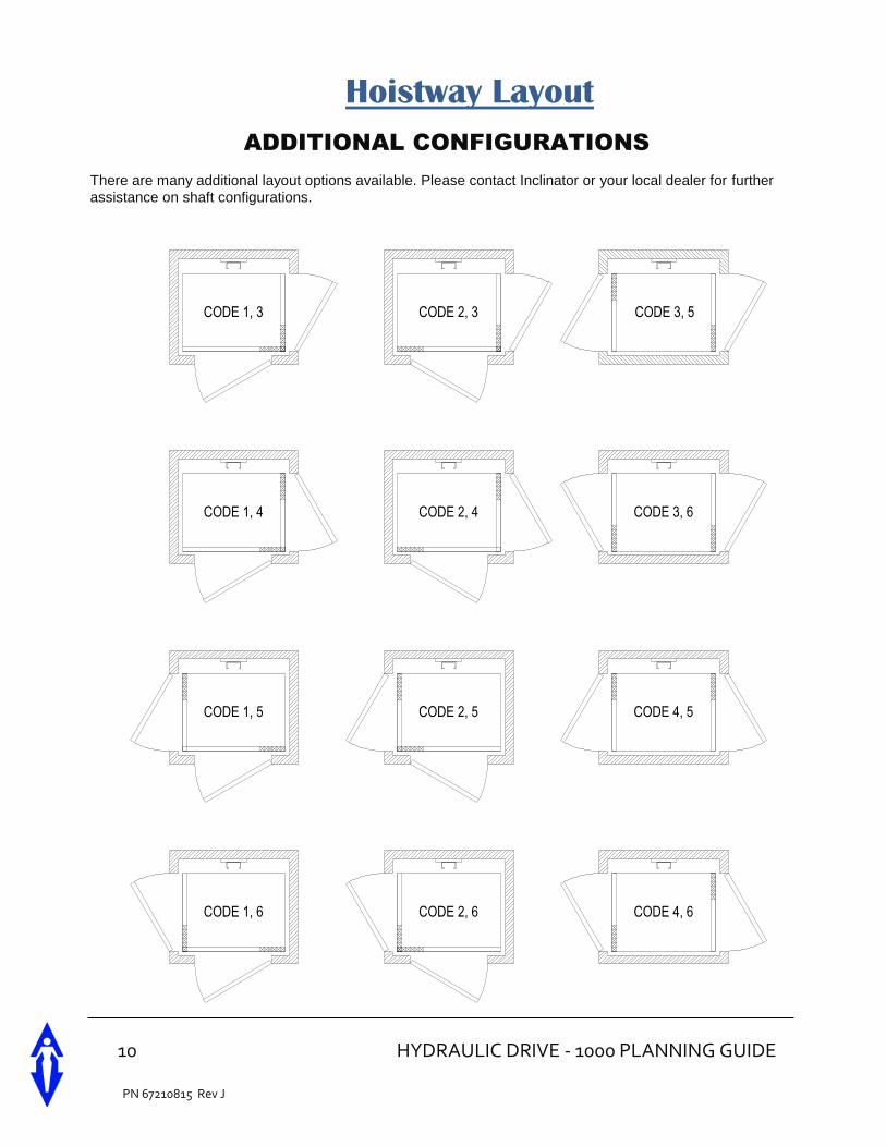
Hoistway Layout
ADDITIONAL CONFIGURATIONS
There are many additional layout options available. Please contact Inclinator or your local dealer for further assistance on shaft configurations.
CODE 1, 5
CODE 2, 4 CODE 3, 6
CODE 4, 5CODE 2, 5
CODE 1, 4
CODE 4, 6
CODE 3, 5
CODE 2, 6
CODE 2, 3
CODE 1, 6
CODE 1, 3
HYDRAULIC DRIVE – 1000 PLANNING GUIDE 11
PN 67210815 Rev J
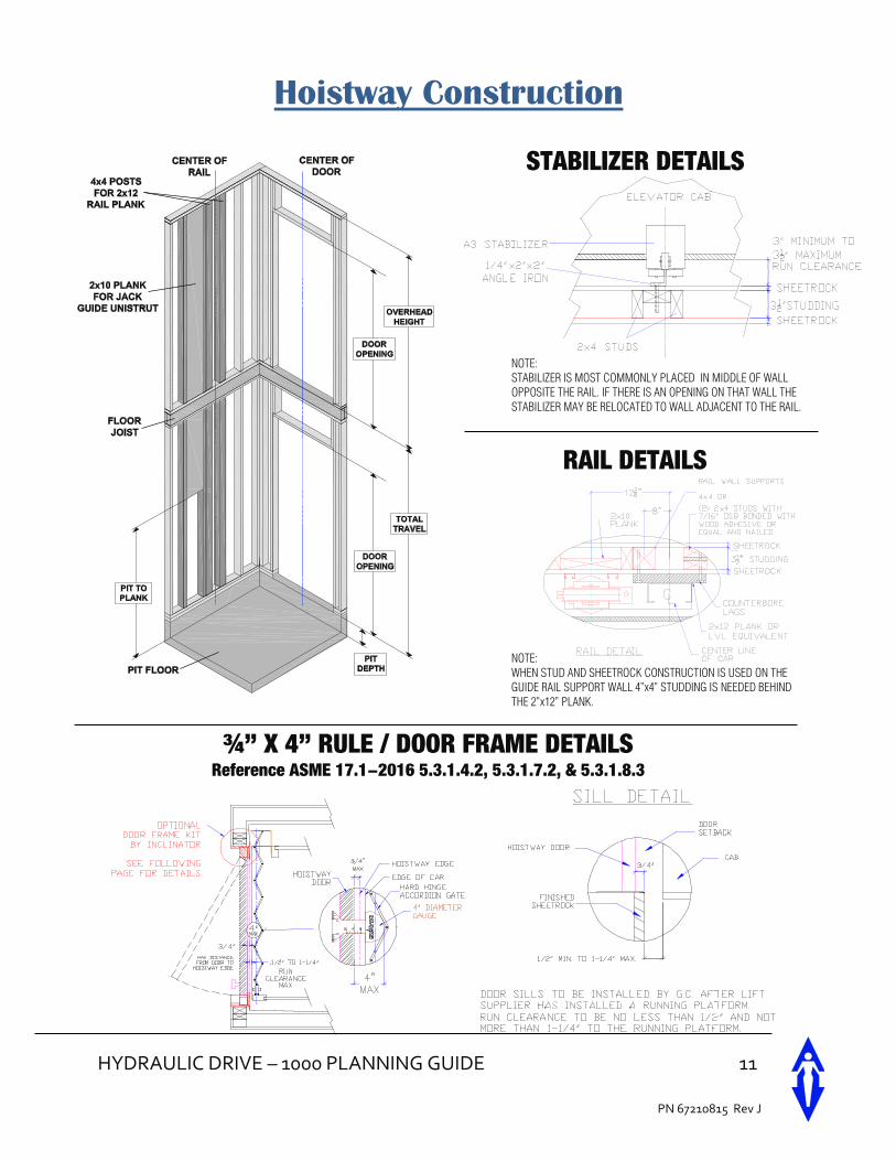
Hoistway Construction
RAIL DETAILS
NOTE:
STABILIZER IS MOST COMMONLY PLACED IN MIDDLE OF WALL
OPPOSITE THE RAIL. IF THERE IS AN OPENING ON THAT WALL THE
STABILIZER MAY BE RELOCATED TO WALL ADJACENT TO THE RAIL.
STABILIZER DETAILS
NOTE:
WHEN STUD AND SHEETROCK CONSTRUCTION IS USED ON THE
GUIDE RAIL SUPPORT WALL 4”x4” STUDDING IS NEEDED BEHIND
THE 2”x12” PLANK.
¾” X 4” RULE / DOOR FRAME DETAILS Reference ASME 17.1-2016 5.3.1.4.2, 5.3.1.7.2, & 5.3.1.8.3
12 HYDRAULIC DRIVE - 1000 PLANNING GUIDE
PN 67210815 Rev J
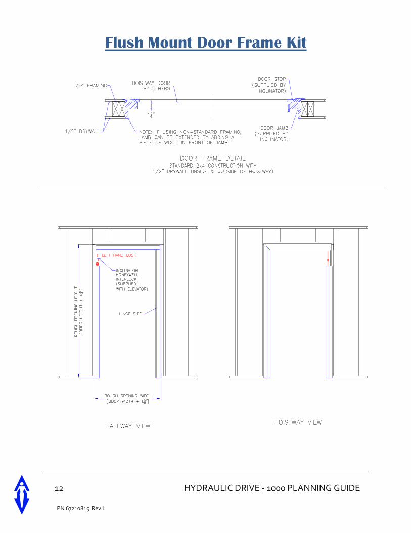
Flush Mount Door Frame Kit
HYDRAULIC DRIVE – 1000 PLANNING GUIDE 13
PN 67210815 Rev J
Alternate Hoistway Construction
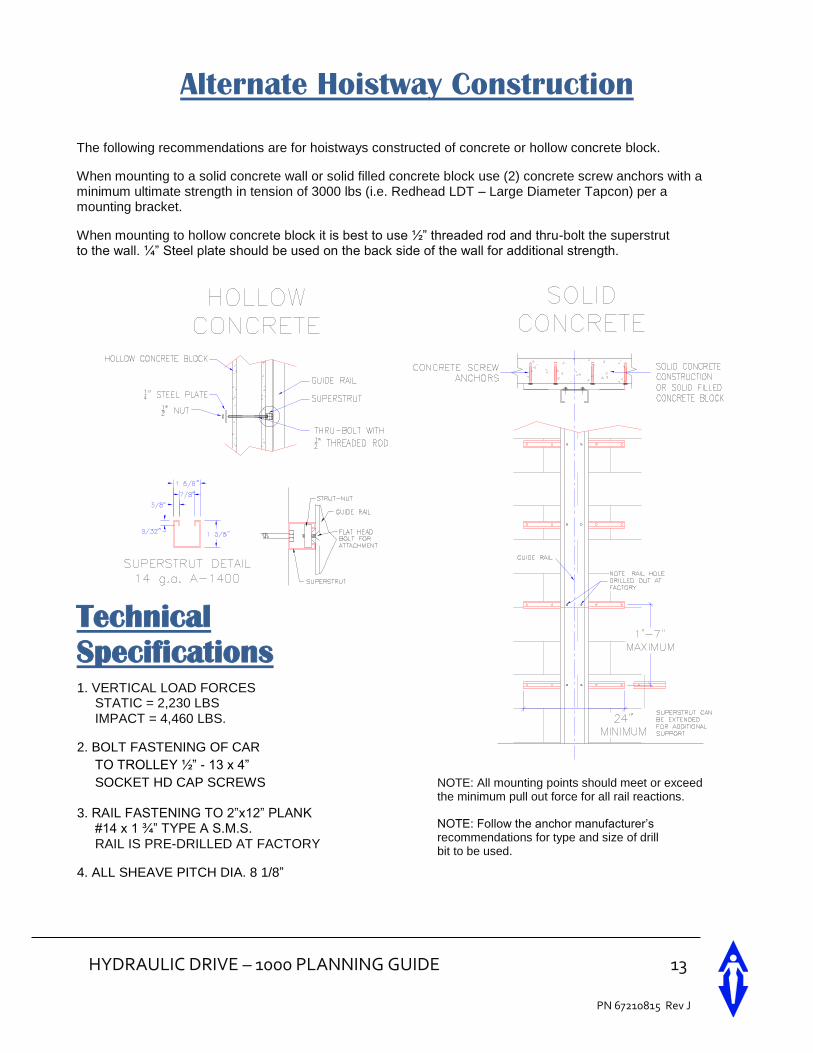
The following recommendations are for hoistways constructed of concrete or hollow concrete block.
When mounting to a solid concrete wall or solid filled concrete block use (2) concrete screw anchors with a minimum ultimate strength in tension of 3000 lbs (i.e. Redhead LDT – Large Diameter Tapcon) per a mounting bracket.
When mounting to hollow concrete block it is best to use ½” threaded rod and thru-bolt the superstrut to the wall. ¼” Steel plate should be used on the back side of the wall for additional strength.
Technical
Specifications
1. VERTICAL LOAD FORCES STATIC = 2,230 LBS IMPACT = 4,460 LBS.
2. BOLT FASTENING OF CAR
TO TROLLEY ½” - 13 x 4”
SOCKET HD CAP SCREWS
3. RAIL FASTENING TO 2”x12” PLANK #14 x 1 ¾” TYPE A S.M.S. RAIL IS PRE-DRILLED AT FACTORY
4. ALL SHEAVE PITCH DIA. 8 1/8”
NOTE: All mounting points should meet or exceed the minimum pull out force for all rail reactions.
NOTE: Follow the anchor manufacturer’s recommendations for type and size of drill bit to be used.
14 HYDRAULIC DRIVE - 1000 PLANNING GUIDE
PN 67210815 Rev J
Hoistway Specifications
The following specs are to be provided by the General Contractor (GC), except as noted, prior to Elevator Contractor (EC) installing the elevator equipment.
1. Environmental requirements for hoistway:
a. Temperature should be maintained between 400 F to 1000 F.
b. Should not be exposed to the elements.
2. Pit Requirements:
a. Substantial level pit floor slab to support 4,460 lbs. impact load.
b. Waterproof pit minimum 10” below lowest floor level.
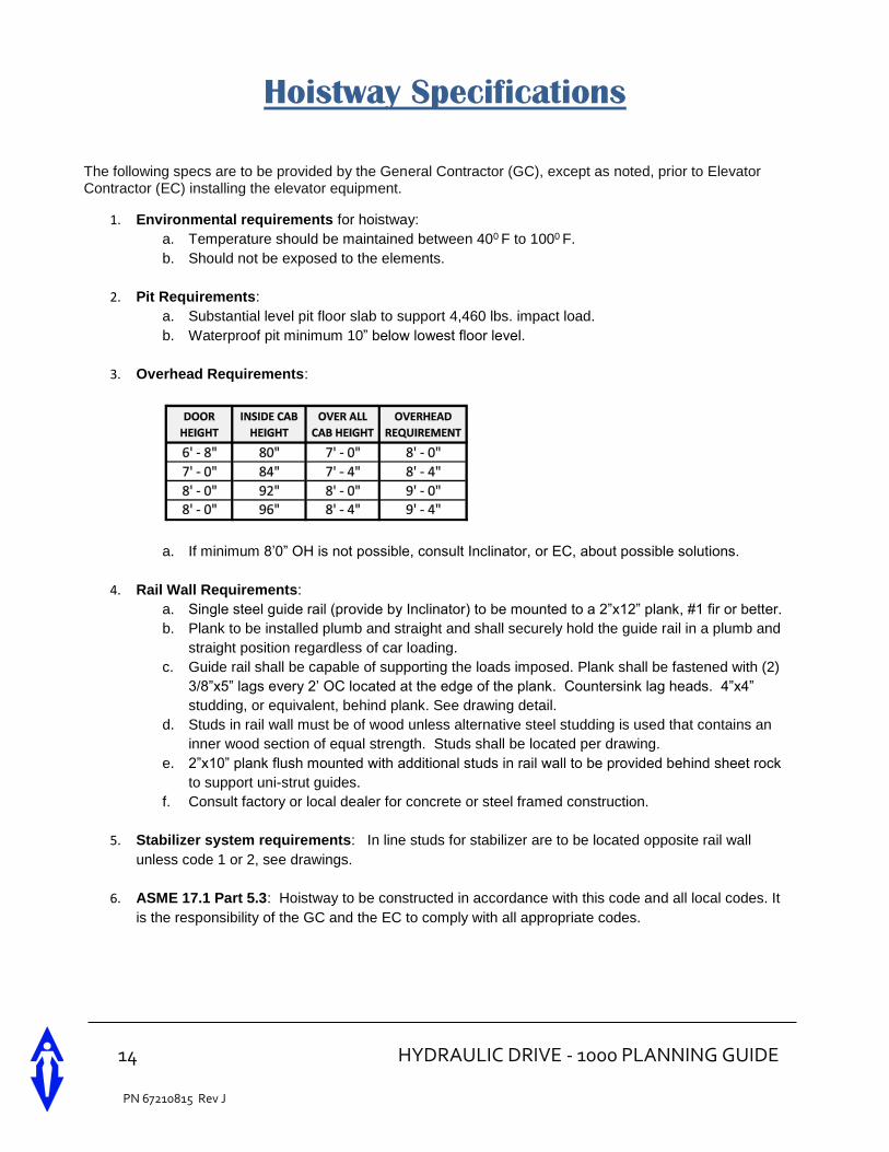
3. Overhead Requirements:
a. If minimum 8’0” OH is not possible, consult Inclinator, or EC, about possible solutions.
4. Rail Wall Requirements:
a. Single steel guide rail (provide by Inclinator) to be mounted to a 2”x12” plank, #1 fir or better.
b. Plank to be installed plumb and straight and shall securely hold the guide rail in a plumb and
straight position regardless of car loading.
c. Guide rail shall be capable of supporting the loads imposed. Plank shall be fastened with (2)
3/8”x5” lags every 2’ OC located at the edge of the plank. Countersink lag heads. 4”x4”
studding, or equivalent, behind plank. See drawing detail.
d. Studs in rail wall must be of wood unless alternative steel studding is used that contains an
inner wood section of equal strength. Studs shall be located per drawing.
e. 2”x10” plank flush mounted with additional studs in rail wall to be provided behind sheet rock
to support uni-strut guides.
f. Consult factory or local dealer for concrete or steel framed construction.
5. Stabilizer system requirements: In line studs for stabilizer are to be located opposite rail wall
unless code 1 or 2, see drawings.
6. ASME 17.1 Part 5.3: Hoistway to be constructed in accordance with this code and all local codes. It
is the responsibility of the GC and the EC to comply with all appropriate codes.
HYDRAULIC DRIVE – 1000 PLANNING GUIDE 15
PN 67210815 Rev J
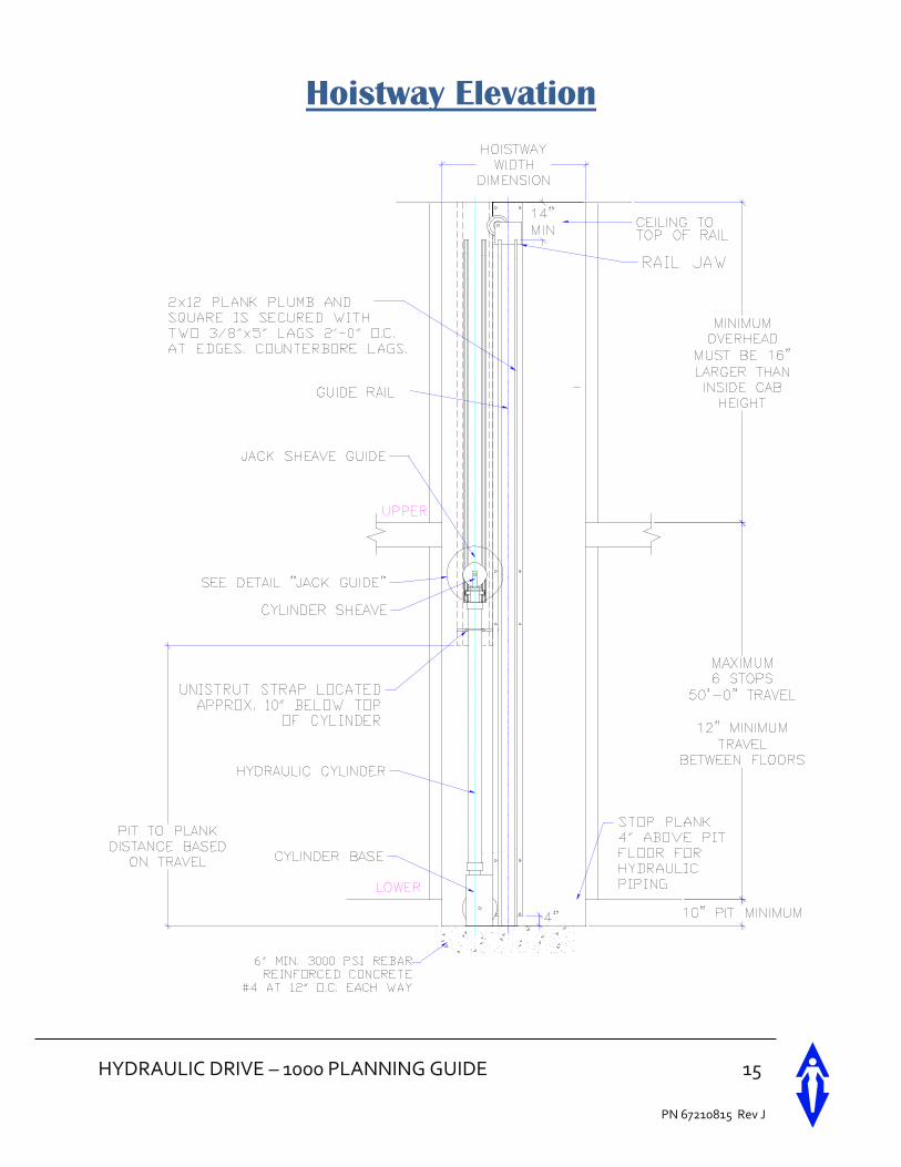
Hoistway Elevation
16 HYDRAULIC DRIVE - 1000 PLANNING GUIDE
PN 67210815 Rev J
3 1
G N
T A
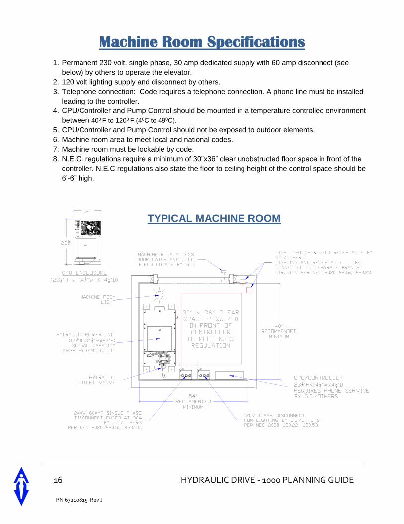
Machine Room Specifications
1. Permanent 230 volt, single phase, 30 amp dedicated supply with 60 amp disconnect (see
below) by others to operate the elevator.
2. 120 volt lighting supply and disconnect by others.
3. Telephone connection: Code requires a telephone connection. A phone line must be installed
leading to the controller.
4. CPU/Controller and Pump Control should be mounted in a temperature controlled environment
between 400 F to 1200 F (40C to 490C).
5. CPU/Controller and Pump Control should not be exposed to outdoor elements.
6. Machine room area to meet local and national codes.
7. Machine room must be lockable by code.
8. N.E.C. regulations require a minimum of 30”x36” clear unobstructed floor space in front of the
controller. N.E.C regulations also state the floor to ceiling height of the control space should be
6’-6” high.
TYPICAL MACHINE ROOM
HYDRAULIC DRIVE – 1000 PLANNING GUIDE 17
PN 67210815 Rev J
G N
T A
G N
T A
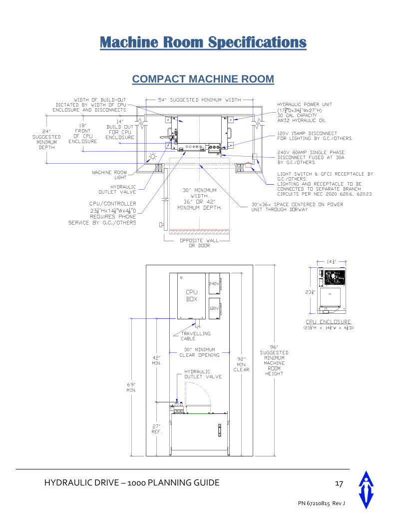
Machine Room Specifications
COMPACT MACHINE ROOM
18 HYDRAULIC DRIVE - 1000 PLANNING GUIDE
PN 67210815 Rev J
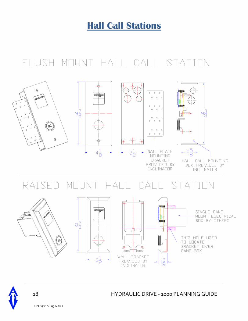
Hall Call Stations
HYDRAULIC DRIVE – 1000 PLANNING GUIDE 19
PN 67210815 Rev J
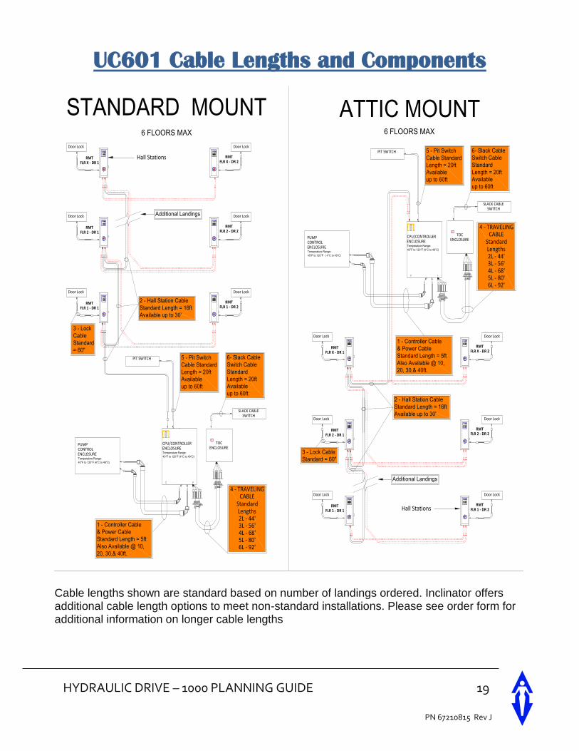
UC601 Cable Lengths and Components
CALL
CALL
RMTFLR 1 - DR 1
Door Lock
CALL
RMTFLR 1 - DR 2
CALL
CALL
CALL
Door Lock
Door Lock Door Lock
Door Lock Door Lock
TOCENCLOSURE
RU
N
ST
OP
RMTFLR 2 - DR 1
RMTFLR 2 - DR 2
RMTFLR X - DR 1
RMTFLR X - DR 2
CALL
CALL
RMTFLR 1 - DR 1
Door Lock
CALL
RMTFLR 1 - DR 2
CALL
CALL
CALL
Door Lock
Door Lock Door Lock
Door Lock Door Lock
CPU/CONTROLLERENCLOSURETemperature Range:
40°F to 120°F (4°C to 49°C)
TOCENCLOSURE
RU
N
ST
OP
RMTFLR 2 - DR 1
RMTFLR 2 - DR 2
RMTFLR X - DR 1
RMTFLR X - DR 2
STANDARD MOUNT6 FLOORS MAX
ATTIC MOUNT6 FLOORS MAX
Hall Stations
Hall Stations
Additional Landings
Additional Landings
2 - Hall Station Cable
Standard Length = 16ft
Available up to 30'
4 - TRAVELINGCABLE
StandardLengths2L - 44'3L - 56'4L - 68'5L - 80'6L - 92'
3 - Lock Cable
Standard = 60"
4 - TRAVELINGCABLE
StandardLengths2L - 44'3L - 56'4L - 68'5L - 80'6L - 92'
2 - Hall Station Cable
Standard Length = 16ft
Available up to 30'
PIT SWITCH
SLACK CABLESWITCH
5 - Pit Switch
Cable Standard
Length = 20ft
Available
up to 60ft
6- Slack Cable
Switch Cable
Standard
Length = 20ft
Available
up to 60ft
PIT SWITCH
SLACK CABLESWITCH
5 - Pit Switch
Cable Standard
Length = 20ft
Available
up to 60ft
6- Slack Cable
Switch Cable
Standard
Length = 20ft
Available
up to 60ft
CPU/CONTROLLERENCLOSURETemperature Range:
40°F to 120°F (4°C to 49°C)
PUMPCONTROLENCLOSURETemperature Range:
40°F to 120°F (4°C to 49°C)
3 - Lock
Cable
Standard
= 60"
1 - Controller Cable
& Power Cable
Standard Length = 5ft
Also Available @ 10,
20, 30,& 40ft.
1 - Controller Cable
& Power Cable
Standard Length = 5ft
Also Available @ 10,
20, 30,& 40ft.
Cable lengths shown are standard based on number of landings ordered. Inclinator offers additional cable length options to meet non-standard installations. Please see order form for additional information on longer cable lengths
20 HYDRAULIC DRIVE - 1000 PLANNING GUIDE
PN 67210815 Rev J
Warranty
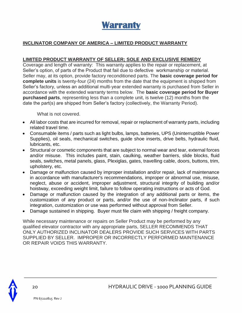
INCLINATOR COMPANY OF AMERICA – LIMITED PRODUCT WARRANTY LIMITED PRODUCT WARRANTY OF SELLER; SOLE AND EXCLUSIVE REMEDY Coverage and length of warranty: This warranty applies to the repair or replacement, at Seller’s option, of parts of the Product that fail due to defective workmanship or material. Seller may, at its option, provide factory reconditioned parts. The basic coverage period for complete units is twenty-four (24) months from the date that the equipment is shipped from Seller’s factory, unless an additional multi-year extended warranty is purchased from Seller in accordance with the extended warranty terms below. The basic coverage period for Buyer purchased parts, representing less than a complete unit, is twelve (12) months from the date the part(s) are shipped from Seller’s factory (collectively, the Warranty Period).
What is not covered.
All labor costs that are incurred for removal, repair or replacment of warranty parts, including related travel time.
Consumable items / parts such as light bulbs, lamps, batteries, UPS (Uninterruptible Power Supplies), oil seals, mechanical switches, guide shoe inserts, drive belts, hydraulic fluid, lubricants, etc.
Structural or cosmetic components that are subject to normal wear and tear, external forces and/or misuse. This includes paint, stain, caulking, weather barriers, slide blocks, fluid seals, switches, metal panels, glass, Plexiglas, gates, travelling cable, doors, buttons, trim, upholstery, etc.
Damage or malfunction caused by improper installation and/or repair, lack of maintenance in accordance with manufacturer's recommendations, improper or abnormal use, misuse, neglect, abuse or accident, improper adjustment, structural integrity of building and/or hoistway, exceeding weight limit, failure to follow operating instructions or acts of God.
Damage or malfunction caused by the integration of any additional parts or items, the customization of any product or parts, and/or the use of non-Inclinator parts, if such integration, customization or use was performed without approval from Seller.
Damage sustained in shipping. Buyer must file claim with shipping / freight company.
While necessary maintenance or repairs on Seller Product may be performed by any qualified elevator contractor with any appropriate parts, SELLER RECOMMENDS THAT ONLY AUTHORIZED INCLINATOR DEALERS PROVIDE SUCH SERVICES WITH PARTS SUPPLIED BY SELLER. IMPROPER OR INCORRECTLY PERFORMED MAINTENANCE OR REPAIR VOIDS THIS WARRANTY.
HYDRAULIC DRIVE – 1000 PLANNING GUIDE 21
PN 67210815 Rev J
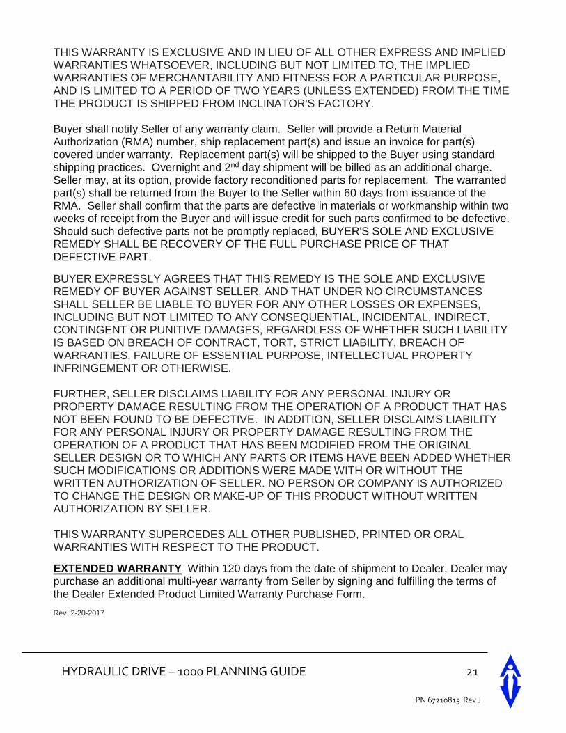
THIS WARRANTY IS EXCLUSIVE AND IN LIEU OF ALL OTHER EXPRESS AND IMPLIED WARRANTIES WHATSOEVER, INCLUDING BUT NOT LIMITED TO, THE IMPLIED WARRANTIES OF MERCHANTABILITY AND FITNESS FOR A PARTICULAR PURPOSE, AND IS LIMITED TO A PERIOD OF TWO YEARS (UNLESS EXTENDED) FROM THE TIME THE PRODUCT IS SHIPPED FROM INCLINATOR'S FACTORY. Buyer shall notify Seller of any warranty claim. Seller will provide a Return Material Authorization (RMA) number, ship replacement part(s) and issue an invoice for part(s) covered under warranty. Replacement part(s) will be shipped to the Buyer using standard shipping practices. Overnight and 2nd day shipment will be billed as an additional charge. Seller may, at its option, provide factory reconditioned parts for replacement. The warranted part(s) shall be returned from the Buyer to the Seller within 60 days from issuance of the RMA. Seller shall confirm that the parts are defective in materials or workmanship within two weeks of receipt from the Buyer and will issue credit for such parts confirmed to be defective. Should such defective parts not be promptly replaced, BUYER'S SOLE AND EXCLUSIVE REMEDY SHALL BE RECOVERY OF THE FULL PURCHASE PRICE OF THAT DEFECTIVE PART.
BUYER EXPRESSLY AGREES THAT THIS REMEDY IS THE SOLE AND EXCLUSIVE REMEDY OF BUYER AGAINST SELLER, AND THAT UNDER NO CIRCUMSTANCES SHALL SELLER BE LIABLE TO BUYER FOR ANY OTHER LOSSES OR EXPENSES, INCLUDING BUT NOT LIMITED TO ANY CONSEQUENTIAL, INCIDENTAL, INDIRECT, CONTINGENT OR PUNITIVE DAMAGES, REGARDLESS OF WHETHER SUCH LIABILITY IS BASED ON BREACH OF CONTRACT, TORT, STRICT LIABILITY, BREACH OF WARRANTIES, FAILURE OF ESSENTIAL PURPOSE, INTELLECTUAL PROPERTY INFRINGEMENT OR OTHERWISE. FURTHER, SELLER DISCLAIMS LIABILITY FOR ANY PERSONAL INJURY OR PROPERTY DAMAGE RESULTING FROM THE OPERATION OF A PRODUCT THAT HAS NOT BEEN FOUND TO BE DEFECTIVE. IN ADDITION, SELLER DISCLAIMS LIABILITY FOR ANY PERSONAL INJURY OR PROPERTY DAMAGE RESULTING FROM THE OPERATION OF A PRODUCT THAT HAS BEEN MODIFIED FROM THE ORIGINAL SELLER DESIGN OR TO WHICH ANY PARTS OR ITEMS HAVE BEEN ADDED WHETHER SUCH MODIFICATIONS OR ADDITIONS WERE MADE WITH OR WITHOUT THE WRITTEN AUTHORIZATION OF SELLER. NO PERSON OR COMPANY IS AUTHORIZED TO CHANGE THE DESIGN OR MAKE-UP OF THIS PRODUCT WITHOUT WRITTEN AUTHORIZATION BY SELLER. THIS WARRANTY SUPERCEDES ALL OTHER PUBLISHED, PRINTED OR ORAL WARRANTIES WITH RESPECT TO THE PRODUCT.
EXTENDED WARRANTY Within 120 days from the date of shipment to Dealer, Dealer may purchase an additional multi-year warranty from Seller by signing and fulfilling the terms of the Dealer Extended Product Limited Warranty Purchase Form. Rev. 2-20-2017
22 HYDRAULIC DRIVE - 1000 PLANNING GUIDE
PN 67210815 Rev J
HYDRAULIC DRIVE – 1000 PLANNING GUIDE 23
PN 67210815 Rev J
24 HYDRAULIC DRIVE - 1000 PLANNING GUIDE
PN 67210815 Rev J
601 Gibson Blvd, Harrisburg, PA 17104 | 800-343-9007 | www.INCLINATOR.com