Embed Size (px)
Citation preview
Incremental3D ReconstructionUsingStereoImageSequences
by
Tai JingMoyung
A thesis
presentedto theUniversityof Waterloo
in fulfilment of the
thesisrequirementfor thedegreeof
Masterof AppliedScience
in
SystemsDesignEngineering
Waterloo,Ontario,Canada,2000
c�
Tai JingMoyung2000

I herebydeclarethatI amthesoleauthorof this thesis.
I authorizethe University of Waterlooto lend this thesisto otherinstitutionsor individuals for
thepurposeof scholarlyresearch.
I further authorizethe University of Waterlooto reproducethis thesisby photocopying or by
othermeans,in total or in part,at therequestof otherinstitutionsor individualsfor thepurpose
of scholarlyresearch.
ii

The University of Waterloorequiresthe signaturesof all personsusing or photocopying this
thesis.Pleasesignbelow, andgiveaddressanddate.
iii
Abstract
In the last two decades,a tremendousamount of researchhas been done in the area of
reconstructingthree-dimensionalobjects from two-dimensionalcameraimages. One major
challengeof the reconstructionproblemis to find featurecorrespondences,that is, to locate
the projectionsof the samethree-dimensionalgeometricalor textural featureon two or more
images.Classicalapproachesto reconstructionfocuson estimatingstructureeitherfrom stereo
imagepairsor from monocularimagesequences.Limitations in bothof theseapproacheshave
motivatedagrowing interestin computingstructurefrom stereoimagesequences;however, most
existing techniquesin this areaassumethat featurecorrespondencesareestablishedin a previ-
ousstep,or thatthey usedomainspecificassumptionsthatareinappropriatein otherapplications.
In this thesis,I presenta robust, incremental3D reconstructionalgorithm using stereoimage
sequences.Theproposedmethodaddressesthe problemof establishingaccuratefeaturecorre-
spondences.Furthermore,the algorithmdevelopsan incrementallydenserepresentationof the
reconstructedobjectthroughabootstrapfeaturematchingprocess.Wearespecificallyinterested
in theapplicationof this approachin thespacecontext for suchpurposesassatelliteidentifica-
tion, grasping,dockingandfault diagnosis.Resultsdemonstratingthepotentialof this approach
arepresented.Conclusionsaredrawn anda list of possibilitiesfor futurework arediscussed.
iv

Acknowledgements
First and foremost, I would like to thank my supervisor, Dr. Paul Fieguth, for his support
and encouragementfor the past two years. I am greatly indebted to him for the many
occasionsin which he has gone out of his way to assistin the timely completionof this
thesis. Dr. Fieguth has beenan ongoing inspiration for me not only in terms of academic
endeavors, but his charismaticpersonalityhas also mademy graduatestudiesa much more
interestingand rewarding experience. As the first studentto completea Master degree un-
derhis full supervisionfrom startto finish,I hopethisthesishasnotdisappointedhim in any way.
I would like to thankNaturalSciencesandEngineeringResearchCouncil (NSERC)of Canada
for funding the researchin this thesisthrougha PostgraduateScholarship(PGSA), andMac-
DonaldDetwiller SpaceandAdvancedRoboticsInc. for motivatingmy researchandproviding
test data. I would also like to thank my readers,Dr. Carolyn MacGregor and Dr. Medhat
Moussa,for their valuablecommentson the thesis. Furthermore,I thank Dr. Ed Jernigan
and all the other membersof the Vision and Image Processinggroup for the eye-opening
discussionson variousresearchinterests,andespeciallyfor the engagingconversationsduring
my procrastinationin thedayandthecompany duringmy productivehourslateatnight in thelab.
Many otherpeoplehave contributed to the completionof this thesisin much more intangible
ways. Specialthanksgo to Daniel,Carey, Emily, Amy andNat who hadthe“privilege” to hear
a lot of my whining andsighing,andof course,fellow Exec Committeemembersof UWCCF,
who patientlyheardmy complaintsthat“I have beenvery unproductive” in everyweeklyprayer
meeting.Thegirls from Eric Hamberandundergraddays,aswell asotherbrothersandsisters
from CCFalsodeserve my gratitude.
I owe themostto my family for their love andsupport,especiallyto my “baby” nephew Kester,
whohasgivenmemany laughablemomentsandtaughtmehow to becuriousonceagain.
Finally, I thank God for delivering me throughmany difficult times and giving me countless
blessings,mostimportantof all, thenew life thatHehasgivenmethroughtheLord JesusChrist.
v
Contents
1 Intr oduction 1
1.1 3D Reconstruction . . . . . . . . . . . . . . . . . . . . . . . . . . . . . . . . . 2
1.2 ThesisOverview . . . . . . . . . . . . . . . . . . . . . . . . . . . . . . . . . . 3
2 Background 7
2.1 TheCameraModel . . . . . . . . . . . . . . . . . . . . . . . . . . . . . . . . . 7
2.2 3D Reconstruction . . . . . . . . . . . . . . . . . . . . . . . . . . . . . . . . . 11
2.3 FeatureExtraction. . . . . . . . . . . . . . . . . . . . . . . . . . . . . . . . . . 12
2.4 StructureFromStereo. . . . . . . . . . . . . . . . . . . . . . . . . . . . . . . . 13
2.4.1 StereoGeometry . . . . . . . . . . . . . . . . . . . . . . . . . . . . . . 14
2.4.2 Reconstructionby Triangulation . . . . . . . . . . . . . . . . . . . . . . 16
2.4.3 EpipolarConstraint. . . . . . . . . . . . . . . . . . . . . . . . . . . . . 17
2.4.4 StereoMatchingTechniques. . . . . . . . . . . . . . . . . . . . . . . . 19
2.4.5 AdvantagesandDisadvantages. . . . . . . . . . . . . . . . . . . . . . . 21
2.5 StructureFromMotion . . . . . . . . . . . . . . . . . . . . . . . . . . . . . . . 21
2.5.1 Motion Model . . . . . . . . . . . . . . . . . . . . . . . . . . . . . . . 22
2.5.2 Motion andStructureFromOpticalFlow . . . . . . . . . . . . . . . . . 24
2.5.3 Motion andStructureFromPointFeatures. . . . . . . . . . . . . . . . . 27
2.5.4 Long ImageSequences. . . . . . . . . . . . . . . . . . . . . . . . . . . 28
2.5.5 AdvantagesandDisadvantages. . . . . . . . . . . . . . . . . . . . . . . 29
2.6 Structurefrom StereoImageSequences. . . . . . . . . . . . . . . . . . . . . . 30
2.6.1 AssumedFeatureCorrespondences. . . . . . . . . . . . . . . . . . . . 30
2.6.2 DirectEstimationor Inference . . . . . . . . . . . . . . . . . . . . . . . 31
2.6.3 ConstrainedMatching . . . . . . . . . . . . . . . . . . . . . . . . . . . 32
2.6.4 Summary . . . . . . . . . . . . . . . . . . . . . . . . . . . . . . . . . . 35
vi
3 Incremental3D Reconstruction 36
3.1 ProblemDefinition . . . . . . . . . . . . . . . . . . . . . . . . . . . . . . . . . 36
3.2 Overview of theIncrementalReconstructionAlgorithm . . . . . . . . . . . . . . 38
3.3 Two DimensionalFeatureTracking. . . . . . . . . . . . . . . . . . . . . . . . . 40
3.3.1 Motion andMeasurementModels . . . . . . . . . . . . . . . . . . . . . 42
3.3.2 PredictionandUpdate . . . . . . . . . . . . . . . . . . . . . . . . . . . 43
3.3.3 ModelPriors . . . . . . . . . . . . . . . . . . . . . . . . . . . . . . . . 45
3.3.4 Relationto StereoMatchingandMotion Estimation . . . . . . . . . . . 45
3.4 ThreeDimensionalFeatureTracking . . . . . . . . . . . . . . . . . . . . . . . . 46
3.4.1 Motion andMeasurementModels . . . . . . . . . . . . . . . . . . . . . 47
3.4.2 PredictionandUpdate . . . . . . . . . . . . . . . . . . . . . . . . . . . 48
3.4.3 ModelPriors . . . . . . . . . . . . . . . . . . . . . . . . . . . . . . . . 49
3.5 Multiple HypothesisTrackingandStereoMatching . . . . . . . . . . . . . . . . 50
3.5.1 HypothesisGeneration. . . . . . . . . . . . . . . . . . . . . . . . . . . 51
3.5.2 HypothesisManagement. . . . . . . . . . . . . . . . . . . . . . . . . . 53
4 Simulations 57
4.1 Descriptionof Data . . . . . . . . . . . . . . . . . . . . . . . . . . . . . . . . . 57
4.2 Two DimensionalTracking . . . . . . . . . . . . . . . . . . . . . . . . . . . . . 59
4.3 ThreeDimensionalTracking . . . . . . . . . . . . . . . . . . . . . . . . . . . . 60
4.4 IncrementalReconstruction. . . . . . . . . . . . . . . . . . . . . . . . . . . . . 63
5 ExtensionsFor Real ImageProcessing 72
5.1 Motion Estimation . . . . . . . . . . . . . . . . . . . . . . . . . . . . . . . . . 72
5.1.1 LeastSquaresEstimation. . . . . . . . . . . . . . . . . . . . . . . . . . 73
5.1.2 AssessingEstimateAccuracy . . . . . . . . . . . . . . . . . . . . . . . 75
5.1.3 Modificationto 3D DynamicModel . . . . . . . . . . . . . . . . . . . . 75
5.2 Resultsof IncorporatingMotion Estimation . . . . . . . . . . . . . . . . . . . . 77
5.3 Adding New Features. . . . . . . . . . . . . . . . . . . . . . . . . . . . . . . . 80
5.4 RealImageSequence. . . . . . . . . . . . . . . . . . . . . . . . . . . . . . . . 83
5.5 Conclusion . . . . . . . . . . . . . . . . . . . . . . . . . . . . . . . . . . . . . 90
6 Conclusions 91
6.1 ThesisAchievements . . . . . . . . . . . . . . . . . . . . . . . . . . . . . . . . 91
6.2 LimitationsandFutureWork . . . . . . . . . . . . . . . . . . . . . . . . . . . . 92
vii

A Camera ParametersFor Simulationsand Experiments 97
B WeightedLeastSquaresEstimation of 3D Motion 100
Bibliography 104
viii

List of Tables
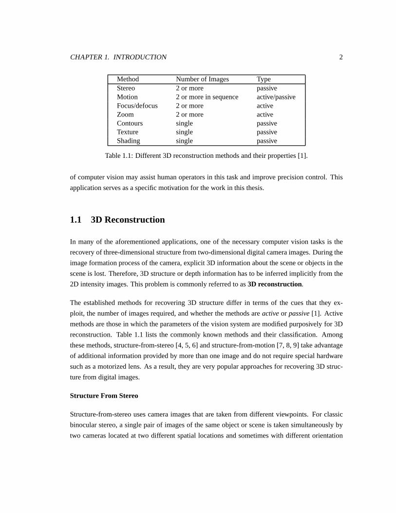
1.1 Different3D reconstructionmethodsandtheirproperties[1]. . . . . . . . . . . . 2
A.1 Parametersof syntheticcamerasystemusedin thesimulationexperiments. . . . 98
A.2 Parametersof PulnixCCD camerasusedin therealimageexperiment. . . . . . . 99
ix
List of Figures
1.1 Two successive imagesof a robotic arm graspinga micro-satellitein spacefor
anddocking.. . . . . . . . . . . . . . . . . . . . . . . . . . . . . . . . . . . . . 4
2.1 Thepinholecamera.. . . . . . . . . . . . . . . . . . . . . . . . . . . . . . . . . 8
2.2 Cameraandimagecoordinatesystems.. . . . . . . . . . . . . . . . . . . . . . . 9
2.3 Parametersthatrelatetheworld, camera,andimagecoordinatesystems.. . . . . 9
2.4 Therelationshipbetweentheworld andcameracoordinatesystems. . . . . . . . 9
2.5 3D reconstructionfrom multiple2D intensityimages . . . . . . . . . . . . . . . 11
2.6 A typical stereocameraconfigurationusedfor capturingstereoimages. . . . . . 14
2.7 3D reconstructionby triangulation.. . . . . . . . . . . . . . . . . . . . . . . . . 15
2.8 Epipolargeometry . . . . . . . . . . . . . . . . . . . . . . . . . . . . . . . . . 17
2.9 Motion field of amoving plane. . . . . . . . . . . . . . . . . . . . . . . . . . . 23
2.10 Theapertureproblem.. . . . . . . . . . . . . . . . . . . . . . . . . . . . . . . . 26
2.11 Thefour-framemodelfor stereoimagesequenceprocessing . . . . . . . . . . . 33
3.1 Theiterative processbetweenmotionestimationandreconstruction.. . . . . . . 39
3.2 Flowchartof theincrementalreconstructionalgorithm. . . . . . . . . . . . . . . 41
3.3 Constraintsin 2D featuretracking. . . . . . . . . . . . . . . . . . . . . . . . . . 41
3.4 Constraintsin 3D featuretracking. . . . . . . . . . . . . . . . . . . . . . . . . . 46
3.5 Deferralof matchingdecisionsby multiple hypothesistracking. . . . . . . . . . 51
3.6 Outlineof themultiple hypothesistrackingalgorithm . . . . . . . . . . . . . . . 52
3.7 An examplesituationin which redundantstereohypothesesarecreated. . . . . . 54
4.1 Syntheticsatellitemodelusedfor simulations . . . . . . . . . . . . . . . . . . . 58
4.2 Samplesyntheticdatapoints. . . . . . . . . . . . . . . . . . . . . . . . . . . . . 59
4.3 Demonstrationof multiple hypothesistwo-dimensionaltracking(1). . . . . . . . 61
4.4 Demonstrationof multiple hypothesistwo-dimensionaltracking(2). . . . . . . . 62
x
4.5 Demonstrationof multiple hypothesisthree-dimensionaltracking(1). . . . . . . 64
4.6 Demonstrationof multiple hypothesisthree-dimensionaltracking(2). . . . . . . 65
4.7 3D pointsreconstructedusingonly 2D featuretrackingandno measurementnoise. 66
4.8 Summaryof resultsfor 2D trackingaloneandno measurementnoise. . . . . . . 67
4.9 3D pointsreconstructedusingonly 2D featuretrackingandmeasurementnoise�����. . . . . . . . . . . . . . . . . . . . . . . . . . . . . . . . . . . . . . . . . 68
4.10 Summaryof resultsfor 2D trackingaloneandnoise�����
). . . . . . . . . . . . 69
4.11 3D pointsreconstructedusingonly 3D feature trackingandmeasurementnoise�����. . . . . . . . . . . . . . . . . . . . . . . . . . . . . . . . . . . . . . . . . 70
4.12 Summaryof resultsfor 3D trackingaloneandnoise�����
. . . . . . . . . . . . . 71
5.1 Shapeof 3D pointestimateuncertaintyat two differentdepths. . . . . . . . . . . 74
5.2 An illustrationof how featuretrackingis affectedby theuncertaintyof predictions. 78
5.3 Resultsof motionestimation.. . . . . . . . . . . . . . . . . . . . . . . . . . . . 79
5.4 3D pointsreconstructedusingcombined2D and3D featuretrackingandmea-
surementnoise�����
. . . . . . . . . . . . . . . . . . . . . . . . . . . . . . . . 81
5.5 Comparisonof reconstructionresultsbetweenusing and not using 3D motion
estimation.. . . . . . . . . . . . . . . . . . . . . . . . . . . . . . . . . . . . . . 82
5.6 Theset-upfor capturinga realstereoimagesequence.. . . . . . . . . . . . . . . 85
5.7 Samplestereoimagepairsin therealimagesequence.. . . . . . . . . . . . . . . 86
5.8 Resultsof reconstructionusingrealimagesequencewith replenishingfeatures. . 88
5.9 Summaryof resultsfor therealimagesequence.. . . . . . . . . . . . . . . . . . 89
xi
Chapter 1
Intr oduction
In very broadterms,humanvision usually refersto both the sensoryandperceptualprocesses
associatedwith whatwe normallycall “seeing.” Similarly, computervision is a very broadfield
of researchthat is intendedfor helpingcomputersandrobots“see.” It includesa setof compu-
tationaltechniquesaimedat estimatingor makingexplicit thegeometricanddynamicproperties
of the three-dimensionalworld from digital images[1, 2]. With theadvancesof digital camera
andimagingtechnology, computervision is playinganincreasinglyimportantrole in automating
tasksthat involve visualsensoryinput. Someexamplesincludeindustrialassemblyandinspec-
tion, robot obstacledetectionandpathplanning,autonomousvehiclenavigation of unfamiliar
environments,imagebasedobjectmodelling,surveillanceandsecurity, medicalimageanalysis,
andhuman-computerinteractionthroughgestureandfacerecognition.
As we live in an ageof informationandspaceexploration, the demandfor satelliteandother
spacerelatedtechnologyhasled to a rapidgrowth of theaerospaceindustry, in which computer
vision hasalsofound its place. Someexamplesincludeautonomousprecisionlanding,survey-
ing, loadingandunloadingequipment,andsatelliteservicingandrepair[3]. Oneapplicationin
which MacDonaldDettwiler SpaceandAdvancedRoboticsLtd.1 hasinterestis theuseof com-
putervision to guidethe retrieval anddockingof micro-satellitesor otherspacemoduleswith
spacecrafts.Camerason boardthe spacecraftprovide the necessaryvisual feedback.The use
1MD Roboticsor simply MDR, is a wholly ownedsubsidiaryof MacDonaldDettwiler andAssociatesLtd. Itsfacilitiesarelocatedin Brampton,OntarioCanada.
1
CHAPTER1. INTRODUCTION 2
Method Numberof Images TypeStereo 2 or more passiveMotion 2 or morein sequence active/passiveFocus/defocus 2 or more activeZoom 2 or more activeContours single passiveTexture single passiveShading single passive
Table1.1: Different3D reconstructionmethodsandtheirproperties[1].
of computervision mayassisthumanoperatorsin this taskandimprove precisioncontrol. This
applicationservesasaspecificmotivationfor thework in this thesis.
1.1 3D Reconstruction
In many of the aforementionedapplications,oneof the necessarycomputervision tasksis the
recoveryof three-dimensionalstructurefrom two-dimensionaldigital cameraimages.Duringthe
imageformationprocessof thecamera,explicit 3D informationaboutthesceneor objectsin the
sceneis lost. Therefore,3D structureor depthinformationhasto beinferredimplicitly from the
2D intensityimages.This problemis commonlyreferredto as3D reconstruction.
The establishedmethodsfor recovering 3D structurediffer in termsof the cuesthat they ex-
ploit, thenumberof imagesrequired,andwhetherthemethodsareactiveor passive[1]. Active
methodsarethosein which theparametersof thevision systemaremodifiedpurposively for 3D
reconstruction.Table1.1 lists the commonlyknown methodsandtheir classification.Among
thesemethods,structure-from-stereo[4, 5, 6] andstructure-from-motion[7, 8, 9] take advantage
of additionalinformationprovidedby morethanoneimageanddo not requirespecialhardware
suchasa motorizedlens.As a result,they arevery popularapproachesfor recovering3D struc-
turefrom digital images.
Structur e From Stereo
Structure-from-stereousescameraimagesthat aretaken from differentviewpoints. For classic
binocularstereo,a singlepair of imagesof thesameobjector sceneis takensimultaneouslyby
two cameraslocatedat two differentspatiallocationsandsometimeswith differentorientation
CHAPTER1. INTRODUCTION 3
aswell. 3D structureis recoveredin a way analogousto humanstereopsis.Computationaltech-
niquesusethelocationoffsetof thecontentbetweenthetwo imagesto perceive depth.However,
the searchfor the correspondingelementsin the two imagesremainsto be a challengingand
unsolvedproblem.
Structur e From Motion
Structure-from-motionusesa monocularsequenceof imagesthataresampledin time. Over the
courseof thesequence,eitherthecamera,thescene,or both thecameraandthesceneundergo
someform of motion. Biological visual systemsusevisual motion to infer propertiesof the
three-dimensionalworld [1]. In a similar manner, theanalysisof theapparentmotionof objects
in digital imagesprovidesastrongvisualcuefor recoveringstructure.Althoughconceptually, 3D
reconstructionfrom motion is similar to that from stereo,thecomputationaltechniquesarevery
differentbecauseof the differentpropertiespossessedby the availableimagesin eachmethod.
Onedrawbackusingmotionis thattheestimatedstructureis only exactto a scalefactorandany
noiseinvolvedin theprocesshasasignificantimpacton theaccuracy of thereconstruction.
Combination of Stereoand Motion
More recently, many researchershave turnedtheir attentionto using stereoimagesequences
to recover 3D information [10, 11, 12, 13, 14, 15, 16, 17, 18, 19, 20]. Multiple stereopairs
of imagesthat arecloselysampledin time arecaptured,which provide both stereoandvisual
motioncuesfor understandingstructure.Furthermore,stereoandmotioncomplementeachother
in a particularfashionwhenthey areintegratedinto a singlereconstructionsystem.Theresults
from pastwork show thattheuseof stereoimagesequencesis apromisingdirectionto pursue,but
existingmethodsapproachtheproblemfrom all differentdirections,eachaddressingaparticular
aspectof thereconstructionproblemwithoutmuchconsiderationof theotheraspects.
1.2 ThesisOverview
Thisthesisisprimarily interestedin theproblemof recovering3D informationaboutarigid object
in a scenefrom digital cameraimages;it builds on the work of many pastefforts to solve the
problemof 3D reconstructionusingstereoimagesequences.Thework in this thesisis motivated
by threemajorobservations:
CHAPTER1. INTRODUCTION 4
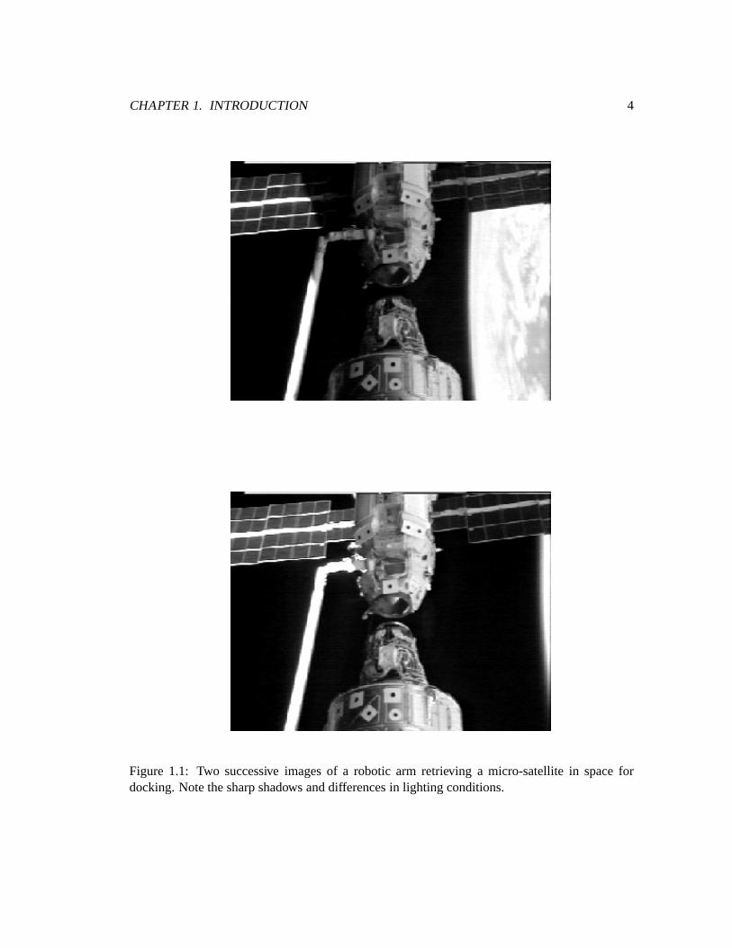
Figure 1.1: Two successive imagesof a robotic arm retrieving a micro-satellitein spacefordocking.Notethesharpshadows anddifferencesin lighting conditions.
CHAPTER1. INTRODUCTION 5
1. Despitethelargeamountof previouswork on thetopic, theproblemof 3D reconstruction
is still unsolved.
2. It hasbeenobserved that for harshenvironmentssuchas outer space,extremelighting
conditions,largedynamicrangeof imagebrightness,specularreflectionandhardshadows
exist (seeFigure1.1). Underthesecircumstances,featureextractionmaynot alwaysgen-
eratereliableresults;thereforethequestionof how onecanstill perform3D reconstruction
well in this casearises.
3. Pastwork on usinga stereoimagesequenceto perform3D reconstructionhasaddressed
specificaspectsof theproblem.However, thereis a lackof unifiedframework for integrat-
ing thedifferentresults.
For thesereasons,this thesisfocuseson developinganalgorithmicframework for reconstructing
3D pointsusingstereoimagesequenceswith thefollowing goals:
� The algorithm builds an incrementallyaccurateand denserepresentationof the recon-
structedobjectusing3D featurepoints.
� Only stereogeometryandmotionconstraintswill beused,henceminimizing themethod’s
relianceon any informationaboutthe extractedfeaturepoints,which may sometimesbe
inconsistentfrom frameto frameor unreliable.
� The framework makesprovisionsfor addressingpossibleproblemsin featureextraction,
suchasmisseddetectionsandfalsefeatures.
� Althoughthis thesisis by no meansattemptingto solve theproblemof 3D reconstruction
in space,the original motivation for examining3D reconstructionwasMDR’s aerospace
application.Therefore,somespecificswith respectto this problemwill beconsideredfor
thedevelopmentof thealgorithm.
Theremainderof this thesisis organisedasfollows:
� Chapter2 providesa literaturereview of existing researchon the3D reconstructionprob-
lem usingstereoand/ormotion information. Theoverall strengthsandweaknessesof es-
tablishedmethodswill be identified. It alsointroducessomeof themathematicalnotation
thatwill beusedthroughoutthis thesis.
CHAPTER1. INTRODUCTION 6
� Chapter3 definestheproblemthatthis thesisis trying to tacklein aqualitativemanner. The
majorcharacteristicsof andtheapproachtakenby this researcharediscussedandjustified,
followedby adescriptionof thebasictheoreticaldevelopmentof theproposedalgorithm.
� Simulationresultsbasedonamock-upsatellitemodelarepresentedin Chapter4, showing
the applicationof the theorydescribedin Chapter3. The limitations of the performance
aredeterminedandexplained.
� Chapter5 discussestwo modifications/extensionsto thework in Chapter3 thatarespecif-
ically important for experimentationon real imagesequences.The resultsof integrat-
ing theseextensionsarealsopresentedin experimentson both syntheticandreal image
squences.
� Finally, the contributionsof this thesisaresummarisedin Chapter6, alongwith a list of
futureresearchrecommendations.
Chapter 2
Background
In this chapter, the imagingmodelandtheproblemof 3D reconstructionaredefined.A survey
of threeexisting approachesto solve this problemwill beprovided: structurefrom stereo(Sec-
tion 2.4),structurefrom motion(Section2.5),andstructurefrom stereoandmotion(Section2.6).
Thelimitationsanddrawbacksof thesetechniqueswill bediscussed.
2.1 The Camera Model
A simplegeometricmodeldescribingthe imageformationprocessof a camerais the pinhole
camera model[1, 2]. As shown in Figure2.1, thecamerais representedasa smallholethrough
which light travels; an intensity of an object is formed on the camera’s imageplanethrough
perspective projection.In orderto determinehow three-dimensionalobjectsin theworld appear
in two-dimensionalcameraimagesgeometrically, we needto definethreedifferentcoordinate
systemsin which to representtheseobjects: the world coordinatesystem(WCS), the camera
coordinatesystem(CCS)andtheimagecoordinatesystem(ICS).
The WCS is a fixed, three-dimensionalframe of referencefor representingthree-dimensional
objectsandscenesin theworld. It is definedby theorthogonal� ��������������� axesandanorigin� � . TheCCSis anotherthree-dimensionalcoordinatesystembut it correspondsto thecamera’s
locationandorientation.As shown in Figure2.2, theCCSis definedby the � ��������������� axes;
7
CHAPTER2. BACKGROUND 8
retinal plane
image planef
object
l
pinhole
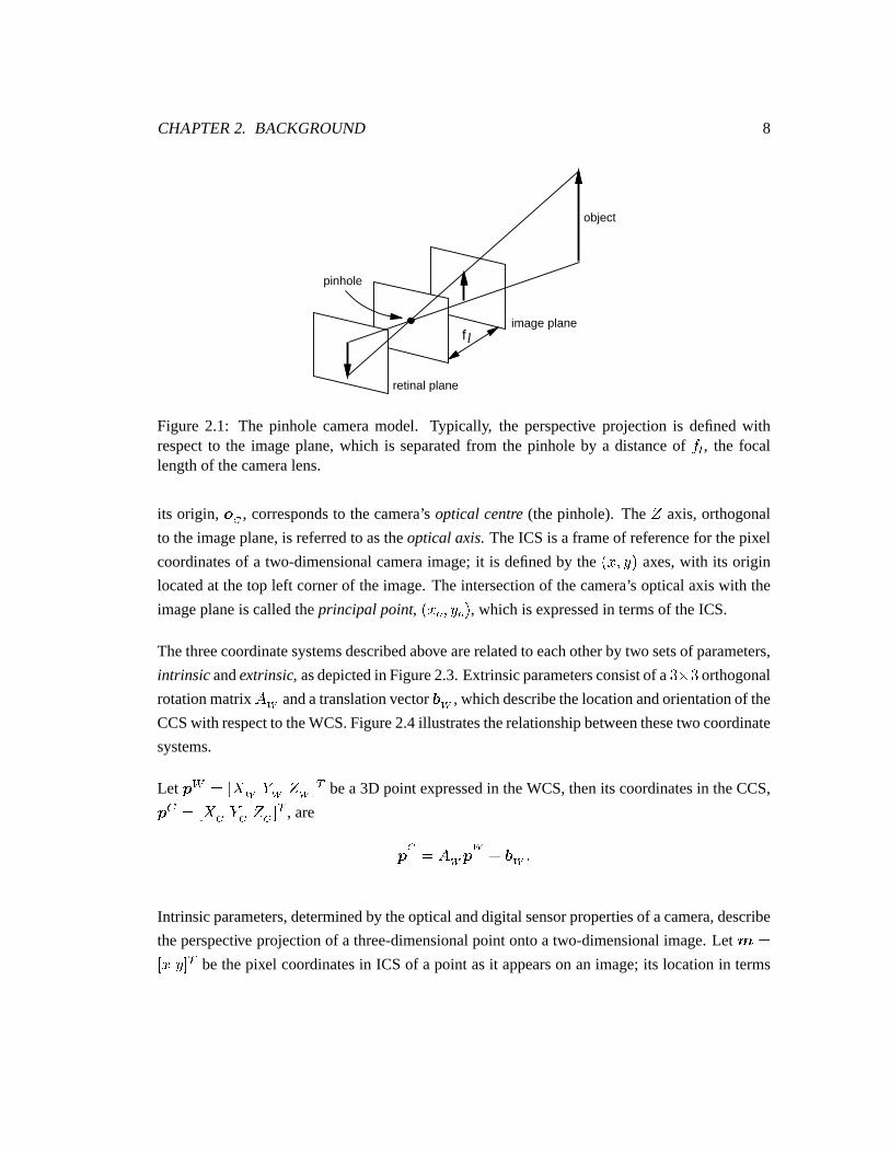
Figure 2.1: The pinhole cameramodel. Typically, the perspective projectionis definedwithrespectto the imageplane,which is separatedfrom the pinholeby a distanceof ��� , the focallengthof thecameralens.
its origin, � � , correspondsto thecamera’s optical centre (thepinhole). The � axis,orthogonal
to theimageplane,is referredto astheopticalaxis. TheICS is a frameof referencefor thepixel
coordinatesof a two-dimensionalcameraimage;it is definedby the �������� axes,with its origin
locatedat thetop left cornerof theimage.Theintersectionof thecamera’s opticalaxiswith the
imageplaneis calledtheprincipal point, ��! "���# $� , which is expressedin termsof theICS.
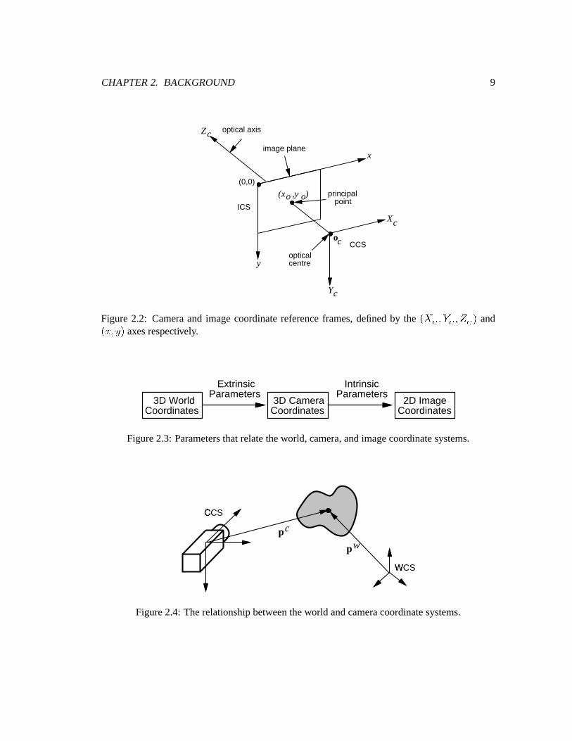
Thethreecoordinatesystemsdescribedabovearerelatedto eachotherby two setsof parameters,
intrinsic andextrinsic, asdepictedin Figure2.3.Extrinsicparametersconsistof a %!&'% orthogonal
rotationmatrix ()� andatranslationvector *#� , whichdescribethelocationandorientationof the
CCSwith respectto theWCS.Figure2.4illustratestherelationshipbetweenthesetwo coordinate
systems.
Let +�, �.- �����/���'021 bea 3D point expressedin theWCS,thenits coordinatesin theCCS,
+�3 �.- �4�!�5���60 1 , are
+ � � (7�)+ �98 *#�;:
Intrinsicparameters,determinedby theopticalanddigital sensorpropertiesof acamera,describe
theperspective projectionof a three-dimensionalpoint ontoa two-dimensionalimage.Let < �- �4�=0 1 bethepixel coordinatesin ICS of a point asit appearson animage;its locationin terms
CHAPTER2. BACKGROUND 9
Z
X
Y
x
y
(x ,y )o o
oc
(0,0)
image plane
optical axis
opticalcentre
c
c
c
CCS
ICS
principal point
Figure2.2: Cameraand imagecoordinatereferenceframes,definedby the � �>������������� and�������� axesrespectively.
3D WorldCoordinates
2D ImageCoordinates
3D CameraCoordinates
IntrinsicParameters
ExtrinsicParameters
Figure2.3: Parametersthatrelatetheworld, camera,andimagecoordinatesystems.
pc
wp
WCS?
CCS@
Figure2.4: Therelationshipbetweentheworld andcameracoordinatesystems.
CHAPTER2. BACKGROUND 10
of thepoint’s coordinatesin theCCSis
� � ���A �B=C ���8 � �
� � ���D���B#E ���8 � � (2.1)
where
� ��� is thefocal lengthof thecameralens(mm),
�FB$G and B$H aretheeffective pixel width andheightof thecamera(mm),and
� �� ��� � is theprincipalpoint of thecamera.
Alternatively, if we defineaprojective matrix
I �JLKM C N � N JOKM E � N N � (2.2)
where
�QP�>PR P
� I �������
�
then
� � �SPR P � � � �>PR P :
As onecanseefrom (2.1), cameraprojectionreducesa three-dimensionalrepresentationof the
world to two dimensions,losingall depthinformation. Furthermore,perspective projectionis a
non-linearprocess,which complicatesthedevelopmentof computervision algorithmsdesigned
to reversethe processto recover the missingdimension. Several approximationsandsimplifi-
cationsarecommonlyusedby the researchcommunityto addressthis problem. Theseinclude
orthographic[21], weakperspective [22], andparaperspective [23] projections.Without lossof
generality, this thesiswill usethefull perspective modelfor cameraprojection.
CHAPTER2. BACKGROUND 11
o1
2o
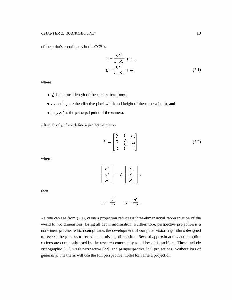
Figure2.5: 3D reconstructionfrom multiple 2D images.�ST and ��U aretheopticalcentresof thecamerascapturingimage
�andimage V respectively.
2.2 3D Reconstruction
3D reconstructionis the problemof recovering depthinformationfrom intensity images. One
commonapproachof 3D reconstructionusesmultiple images. It is basedon the principle that
a physicalpoint in spaceis projectedontodifferentlocationson imagescapturedfrom different
viewpoints, asshown in Figure2.5. The differencein the projectedlocationsis usedto infer
depthinformation.
Specifically, considera rigid object representedby a set of W 3D points, X�+�Y�Z���Z[ , on some
coordinatesystemat frame � . Eachpoint + Y Z��� is projectedonto an image,�Z\ Z��� , which is
capturedfrom aviewpoint ] . Then< \Y Z��� , thepoint’s coordinatesin theICScanbeexpressedin
termsof avector-valuednon-linearfunction ^ :
< \Y_Z��� � ��
� ^`Z]$�Z+�Y�Z���Z�Z: (2.3)
Notethat ^ is asimplificationof theperspective equationsin (2.1) for aspecifiedcamera.
Given a set of imagesthat are taken from different viewpoints ] (structure-from-stereo) or at
differenttimeframes� (structure-from-motion), wemaybeableto reconstructthepoints X�+ Y Z���Z[from acompletesetof theirprojectionsX�< \Y Z���Z[ . Detailsonhow this is accomplishedin thetwo
caseswill bediscussedin Sections2.4and2.5respectively.
CHAPTER2. BACKGROUND 12
Therearetwo computationalsubproblemsassociatedwith 3D reconstructionfrom two or more
images:
1. Featurecorrespondence,
2. Structureestimation.
Thefirst problemis bestexplainedin anexample.For instance,a physical3D point is projected
ontoImageA aspoint 1 andImageB aspoint 2. Points1 and2 aresaidto becorrespondences.
Hence,the featurecorrespondenceor featurematchingproblemis to find wherepoint 2 is on
imageB giventhelocationof point1 onimageA. Humanvisionissuperbin solvingthisproblem,
but theautomationof thisprocessby computersis ratherdifficult. It essentiallyrequiresasearch
on the whole imageB. Applying properconstraintscan narrow down the search,but without
sufficient constraints,theproblembecomesill-posedandambiguitiesarise.
Thesecondproblem,structureestimation,is relatively easyin comparison.It is thecomputation
of thepointset X�+ Y [ afterthecorrespondenceproblemis solved.Thedifficulty of thissubproblem
dependson theamountof a priori informationavailable.If theintrinsicandextrinsicparameters
of the camera(s)areknown for the whole setof images,thenan exact reconstructionin abso-
lute coordinatesis possible.However, theaccuracy of the reconstructedstructureis sensitive to
theaccuracy of theseparameters.Moreover, any errorsin solving the correspondenceproblem
betweentwo imagesalsoaffect the accuracy of the reconstruction.As a consequence,even if
intrinsic andextrinsic parametersareknown, the challengeremainsfor developingalgorithms
thatreducetheeffectsof errorsin thepreprocessingstepson thestructureestimate.
2.3 FeatureExtraction
In the previous section,we have usedthe term feature looselywithout giving it a precisedefi-
nition. In some3D reconstructionapplications,it maybenecessaryto estimatethestructureof
a scenefor every point in the image. However, sometimeswe mayonly be interestedin recon-
structingthe depthof an objector sceneat certainparts. Imagefeaturesusually refer to parts
of animagethathave specialproperties,andthey maycorrespondto partsof anobjector scene
that have structuralsignificance,to regions that have visually identifiabletexturesor intensity
CHAPTER2. BACKGROUND 13
patterns,or to any otherderived propertiesthat canbe localisedon an image. Somecommon
examplesareedges,lines,corners,junctions,ellipses,andzero-crossingsof imagegradients.
Featureextractionis the processof locatingtheseparticularelementson an imageandit is an
intermediatestepfor many computervision applications.The choiceof featuresto extract for
reconstructionvery oftendependson thepropertiesof theobjectsin thescene.Someimportant
factorsto considerareinvariance,easeof detectability, andhow they areeventuallyused.For our
purposes,wewill concentrateonpoint features, featuresthatcanbelocalisedin two dimensions.
Point featuresareeasyto representmathematicallyand they candirectly correspondto three-
dimensionalpoints in space. Many featuresthat can be localisedto a point are usually easy
to detect,andarerelatively consistentacrossdifferent imagescomparedto other featuressuch
asedgesandlines. Therearemany mathematicaldefinitionsof localisedimagestructuresand
sometimesthey arebroadlyidentifiedascorners. The literatureon cornerdetectionis immense
anda few examplesare[24, 25].
Featureextractionis not a focusof this thesissowe would like to avoid discussingthedetailsin
thissection.Weuseapublicly availableimplementationof thework by TomasiandKanade[26],
which is basedon theearlierwork of [27], to extractcornerfeaturesin our experiments.For all
otherdiscussions,weassumethatimagepoint featuresarereadilyavailablefrom aseparate,pre-
processingstep.Sometimeswe will alsorefer to featureson anobject,andthey refer to visible
geometricalor textural elementson a three-dimensionalobjectevenif the featureextractormay
notbeableto detectthem.
2.4 Structure From Stereo
The use of stereopsisfor depth perceptionin humanvision is a well known phenomenon.
Structure-from-stereosimply refersto the classof computervision algorithmsthat appliesthe
sameprinciple for inferring depthinformationfrom imagestaken from differentviewpoints. A
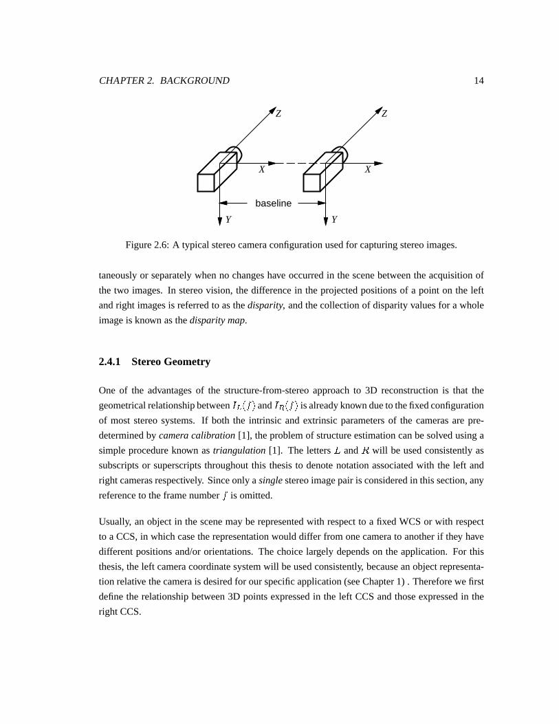
typical binocularstereocamerasystemis illustratedin Figure2.6. In summary, thetwo cameras
aremountedsuchthat their optical axes(the � -axes)arecoplanarandalignedin parallel. The
separationbetweentheopticalcentresof theleft andright camerasis calledthebaseline, andit is
usuallycreatedby atranslationbetweenthecameras’opticalcentresalongtheircommon -axis.
Theleft andright camerasin thestereosystemcapturea pair of images,X �Za Z���Z� �Zb Z���Z[ , simul-
CHAPTER2. BACKGROUND 14
X X
Z Z
Y Y
baseline
Figure2.6: A typical stereocameraconfigurationusedfor capturingstereoimages.
taneouslyor separatelywhenno changeshave occurredin thescenebetweentheacquisitionof
the two images.In stereovision, thedifferencein theprojectedpositionsof a point on the left
andright imagesis referredto asthedisparity, andthecollectionof disparityvaluesfor a whole
imageis known asthedisparitymap.
2.4.1 StereoGeometry
One of the advantagesof the structure-from-stereoapproachto 3D reconstructionis that the
geometricalrelationshipbetween�Za Z��� and
�Zb Z��� isalreadyknown dueto thefixedconfiguration
of most stereosystems.If both the intrinsic andextrinsic parametersof the camerasarepre-
determinedby camera calibration [1], theproblemof structureestimationcanbesolvedusinga
simpleprocedureknown as triangulation [1]. The letters c and d will be usedconsistentlyas
subscriptsor superscriptsthroughoutthis thesisto denotenotationassociatedwith the left and
right camerasrespectively. Sinceonly asinglestereoimagepair is consideredin thissection,any
referenceto theframenumber� is omitted.
Usually, anobjectin thescenemayberepresentedwith respectto a fixedWCSor with respect
to a CCS,in which casetherepresentationwould differ from onecamerato anotherif they have
differentpositionsand/ororientations.Thechoicelargely dependson theapplication.For this
thesis,theleft cameracoordinatesystemwill beusedconsistently, becauseanobjectrepresenta-
tion relative thecamerais desiredfor ourspecificapplication(seeChapter1) . Thereforewefirst
definethe relationshipbetween3D pointsexpressedin the left CCSandthoseexpressedin the
right CCS.
CHAPTER2. BACKGROUND 15
e#f e=g
h f h g
i f
jlk�mon$pq gq f
r q f
s q g
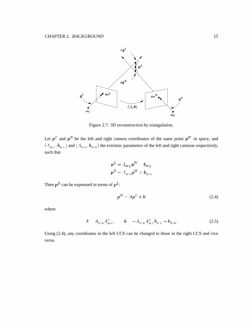
Figure2.7: 3D reconstructionby triangulation.
Let + a and + b be the left and right cameracoordinatesof the samepoint + , in space,and
Z( �ut �v* �ut � and Z( �uw �v* �uw � theextrinsic parametersof theleft andright camerasrespectively,
suchthat
+ a � (7�utx+ , 8 *=�ut+ b � (7�uw6+ , 8 *=�uw
Then + b canbeexpressedin termsof + a :
+ b � (�+ a 8 * (2.4)
where
( � ()�uw�(7y�z�ut � * ��{ (7�uw�(7y�z�ut *|�ut 8 *#�uw�: (2.5)
Using (2.4), any coordinatesin the left CCScanbechangedto thosein the right CCSandvice
versa.
CHAPTER2. BACKGROUND 16
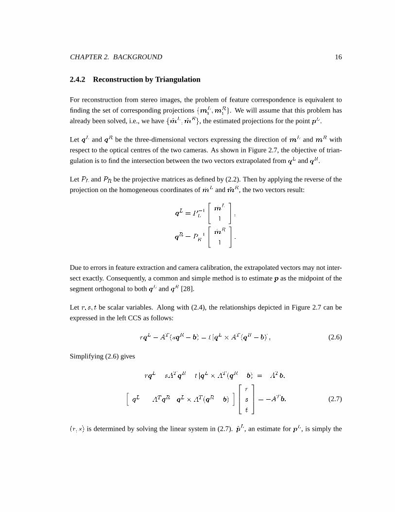
2.4.2 Reconstructionby Triangulation
For reconstructionfrom stereoimages,the problemof featurecorrespondenceis equivalent to
finding thesetof correspondingprojectionsX�< aY �Z< bY [ . We will assumethat this problemhas
alreadybeensolved,i.e.,wehave X~}< a ��}< b [ , theestimatedprojectionsfor thepoint + a .
Let � a and � b be the three-dimensionalvectorsexpressingthe directionof < a and < b with
respectto theopticalcentresof thetwo cameras.As shown in Figure2.7, theobjective of trian-
gulationis to find theintersectionbetweenthetwo vectorsextrapolatedfrom � a and � b .
LetI a
andI b
betheprojective matricesasdefinedby (2.2).Thenby applyingthereverseof the
projectionon thehomogeneouscoordinatesof }< a and }< b , thetwo vectorsresult:
� a � I y�za }< a� �� b � I y�zb }< b� :
Dueto errorsin featureextractionandcameracalibration,theextrapolatedvectorsmaynot inter-
sectexactly. Consequently, a commonandsimplemethodis to estimate+ asthemidpointof the
segmentorthogonalto both � a and � b [28].
Let �x��]���� be scalarvariables.Along with (2.4), the relationshipsdepictedin Figure2.7 canbe
expressedin theleft CCSasfollows:
�x� a { ( 1 Z]O� b { *#� � � - � a &�( 1 o� b { *|��0�� (2.6)
Simplifying (2.6)gives
�|� a { ]�( 1 � b { � - � a &�( 1 o� b { *|��0 ��{ ( 1 *x�� a { ( 1 � b � a &�( 1 o� b { *x�
�]�
��{ ( 1 *x: (2.7)
��x��]�� is determinedby solving the linearsystemin (2.7). }+ a , anestimatefor + a , is simply the
CHAPTER2. BACKGROUND 17
p
o oLR
iepipolar plane
left image right image
epipolar line epipolar line
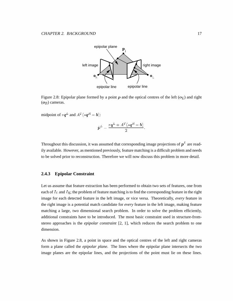
Figure2.8: Epipolarplaneformedby a point + andtheopticalcentresof theleft (� a ) andright(� b ) cameras.
midpointof �|� a and ( 1 Z]�� b { *#� :}+ a � �|� a 8 ( 1 Z]O� b { *|�V :
Throughoutthisdiscussion,it wasassumedthatcorrespondingimageprojectionsof + a areread-
ily available.However, asmentionedpreviously, featurematchingis adifficult problemandneeds
to besolvedprior to reconstruction.Thereforewewill now discussthisproblemin moredetail.
2.4.3 Epipolar Constraint
Let usassumethatfeatureextractionhasbeenperformedto obtaintwo setsof features,onefrom
eachof�Za
and�Zb
; theproblemof featurematchingis to find thecorrespondingfeaturein theright
imagefor eachdetectedfeaturein the left image,or vice versa. Theoretically, every featurein
theright imageis a potentialmatchcandidatefor every featurein theleft image,makingfeature
matchinga large, two dimensionalsearchproblem. In order to solve the problemefficiently,
additionalconstraintshave to be introduced.The mostbasicconstraintusedin structure-from-
stereoapproachesis the epipolar constraint [2, 1], which reducesthe searchproblemto one
dimension.
As shown in Figure2.8, a point in spaceandthe optical centresof the left andright cameras
form a planecalled the epipolar plane. The lines wherethe epipolarplaneintersectsthe two
imageplanesare the epipolar lines, and the projectionsof the point must lie on theselines.
CHAPTER2. BACKGROUND 18
Consequently, giventhelocationof any imagefeaturepointon theleft image,wecannarrow the
searchfor thepoint’s correspondencealongtheepipolarline.
Let � I - < aY 0 bethenormalvectorof theepipolarline of a left imagefeature< aY , where
� I - < aY�0 � � �R :
Theepipolarconstraintimpliesthatthecorrespondenceof < aY in theright imagemustlie on the
line representedby � I - < aY 0 . Mathematically, thismeans
o< bY � 1 � � I - < aY 0 � N � (2.8)
The locationof theepipolarlineson eachof the left andright imagesdependson thegeometry
of thestereosystemandcanbefoundusingtheintrinsicandextrinsicparametersof thecameras.
UsingI a
,I b
, ( and * aspreviously defined,let � beanantisymmetricmatrix suchthat �7� �*�&4� for all 3D vectors� , i.e.,
� � N {���� � H� � N {�� G{�� H � G N :
A %;&�% matrix,known asthe fundamentalmatrix [29], is definedas
� � I y 1b ��( I y�zaandit satisfiestherelationship
o< bY � 1 � � < aY� � N : (2.9)
Thenby comparingtheepipolarconstraintin (2.8)with (2.9),theepipolarline ontheright image
CHAPTER2. BACKGROUND 19
canbefound,where
� I - < aY 0 � � < aY� :
In caseswherethedistribution of featureson the imagesaresparse,theepipolarconstraintmay
besufficient to uniquelysolve thefeaturematchingproblemassumingthat thefeatureextractor
reliably detectscorrespondingpointsin both images.However, asshown in Figure2.8, if there
are more than one extractedfeaturepoints in the right imagethat lie in the proximity of the
epipolarline, the depthof the point in concerncannotbe uniquelydetermined.Thereforethe
epipolarconstraintaloneis notalwaysguaranteedto solve thefeaturecorrespondenceproblem.
2.4.4 StereoMatching Techniques
In orderto furtherconstrainthefeaturematchingproblem,a multitudeof correspondencealgo-
rithmshavebeenproposedin thepasttwo decades[4, 5, 6, 30,31, 32]. Themaingoalof mostof
theseefforts is to limit thesearchspaceor minimizethenumberof matchingcandidatesfor each
featurepoint. Decisionsin matchingprimitivesandstrategiesareaffectedby many application
dependentfactorssuchasimaginggeometry, lighting conditions,andsurfaceproperties.
Local stereomatchingmethodsgenerallybelongto oneof two broadcategories:area-basedand
feature-basedtechniques[33]. Both of thesetechniquesarebasedon a measureof similarity
betweena region or featureof interestin oneimageandthatof theotherimage. In additionto
thesetwo local matchingmethods,phase-basedmethodsconstitutethe third category of stereo
matchingtechniques[34].
Area-basedmethodsassumethat theappearance,that is, the intensityvalues,of a small neigh-
bourhoodof pixels remainconstantfrom oneviewpoint to another. Hence,for all pixels in an
image,a correlationmeasuresuchascrosscorrelationor sumof squareddifferences[1] canbe
usedto find correspondingpixels in theotherimagewith a similar looking neighborhood.The
advantageof thismatchingtechniqueis thatadensedisparitymapis achievable,whichis anasset
for reconstructingthe completesurfacestructureeverythingin the cameras’viewpoints. How-
ever, this techniquerelieson the imageshaving highly texturedregions. Moreover, the choice
of the window sizefor computingthe correlationmeasurehasa significantimpacton the per-
CHAPTER2. BACKGROUND 20
formanceof thealgorithm. Very often, thechoiceof window sizeis arbitrarydependingon the
natureof thescene.Someresearchershavetriedto tacklethisproblemby introducingdeformable
windows [35], adaptive window sizes[36], andmultiple windowing [37].
Feature-basedmethods[6, 30, 32] establishcorrespondencebetweensimilar featuresin apairof
images.Discretefeaturessuchasedges,lines,pointswith highintensityvariation,zero-crossings
of gradients,or high level structuresareextractedfrom intensity information,andmatchingis
only performedon thesefeatures.A distancemetric is usedto assessthesimilarity of features
betweentheimages.Theadvantageof thisapproachis thatfeaturesaregenerallymoreinvariant
thanactualimageintensitiesunderlargeviewpoint variation. However, oftenonly a sparsedis-
paritymapis obtainedbecausethenumberof featuresin animagethataremeaningfulor easyto
matchmaybelimited. Theopenquestionsregardingfeature-basedmatchingareoftenrelatedto
whattypesof featuresshouldbeextractedfor specificapplications,andwhatsimilarity measures
anddistancemetricsarethebestfor eachtypeof features.Therearemany combinationsof pos-
sibilities andthecomplexity of someof theexisting methodsalmostseemtoo overwhelmingto
explore.
Althoughbothareaandfeature-basedlocal matchingmethodsprovide constraintsin additionto
theepipolarconstraint,ambiguitiesin featurematchingoftenstill exist. Somecommonassump-
tionsaremadeto furtherrestrictthesizeof thesearchspace.For example,it maybepossibleto
setlower andupperboundson theamountof disparityallowed becausethescenehasa known
maximumandminimum depths. Moreover, for a typical stereocamerasystemsuchasthat in
Figure2.6, the epipolarlines areparallelwith the horizontalimageaxis andstereodisparityis
restrictedto a horizontalcomponent.In this case,< b will alwayshave a smaller� coordinate
than that of < a , otherwisethe reconstructedpoint will have a negative depth. Furthermore,
consistency of the local matchescanbechecked on a global level. Commonglobal constraints
areuniqueness[4] anddisparitysmoothnesswithin a neighborhood[4] or alongcontours[5].
Theseconstraintsareusuallyenforcedby computationtechniquessuchas relaxationlabelling
[38], hierarchicaloptimization[31], or dynamicprogramming[39].
Phased-basedmethods[40, 41, 42, 34] for stereomatchingusea differentapproachfrom the
othertwo localmatchingmethods.ThesemethodsuseFourierphaseinformationcomputedfrom
theimagesdirectly for matching.Thedifferencebetweentheleft andright Fourier-phaseimages
areusedto computedensedisparitymaps.Theadvantageof this typeof algorithmis thatexplicit
featurematchingis not needed.Someproblemsthat phase-basedmethodshave to tackleare
CHAPTER2. BACKGROUND 21
phasediscontinuitiesandunstablephasewrapping[34].
2.4.5 Advantagesand Disadvantages
As mentionedpreviously, in structure-from-stereo,thegeometryof thecamerasystemis usually
known a priori , providing the convenienceof the epipolarconstraintfor finding featurecorre-
spondences.In addition,sincethebaselinein a typicalstereosystemis large,theresultsof trian-
gulationarereasonablyinsensitive to errorsin featureextraction.However, for thesamereason,
geometricdistortion,occlusionanddifferencesin specularpropertiesdueto varyingviewpoints
becomesignificant,suchthat theproblemof featurecorrespondencebecomesincreasinglydiffi-
cult. All themethodsoutlinedin Section2.4.4for solvingthisproblemtendto becomputationally
expensive andrequirecertainassumptionsaboutthecharacteristicsof the imageswhich do not
alwaysapplyin any generalcase.Moreover, singlepairsof stereoimagesby themselvescanonly
provide partial representationsof thescene.View registrationof multiple stereopairswould be
requiredto obtainmorecomplete3D structureinformation.
2.5 Structure From Motion
While structure-from-stereousesimagestaken from differentviewpointsfor 3D reconstruction,
structure-from-motionusesimagestaken at different time frames. The differencebetweenthe
two approachesis thatstructure-from-motiontypically involvesamonocularsequenceof closely
sampledimagesthataretakenover time, andthateitherthesceneor thecameraor bothhasun-
dergonesomeform of motionover theperiodof theimagesequence.Theunderlyingassumption
mostcommonlyassertedfor structure-from-motionis thatthemotionis smallenoughor thatthe
imagesaresampledfrequentlyenoughso that the imagesdo not changevery much from one
frameto thenext. In otherwords,thebaselinebetweenthecamerasin successive framesis small.
In general,two typesof motion may be presentin an imagesequence:cameramotion, and
movementof the scene. The latter may involve differentobjectsmoving with different kinds
of motion, in which casethe problemof motion segmentationarises.For the specificproblem
discussedin this thesis,we will assumethatthereis only one,rigid, relative motionbetweenthe
cameraandthescene.
CHAPTER2. BACKGROUND 22
2.5.1 Motion Model
As demonstratedin Section2.4,3D reconstructionfrom stereoimagesreliesonknowledgeabout
therelative positionandorientationbetweentheleft andright cameras.Similarly, anunderstand-
ing of the motion that inducesvisual changesin a monocularsequenceis useful in estimating
structure.Thereforea modeldescribingthe motion presentin an imagesequenceis necessary.
Sinceonly onecamerais usedin structure-from-motion,referencesto thecameraposition, c and
d , will beomitted;instead,theframenumber� will beusedto distinguishbetweenconsecutive
imageframes.
Themotionof acamerarelative to anobjectcangenerallybedescribedby atranslationalvelocity
vector � ��- �!�������>� 0 1 andanangularvelocityvector� �.- ���5�����u� 0 1 , definedwith respect
to the cameracoordinatesystem. The instantaneousvelocity of a point +SZ��� expressedin the
CCSis
�+SZ��� ��{ � { ��&�+QZ���Z�where
� ��{�� � {�� � � 8 � � ��� ��{�� � {�� � 8 � � ��� ��{�� � {�� � � 8 � � �: (2.10)
Alternately, we canexpressthecoordinatesof +SZ��� at frame � 8 � in termsof a rotationmatrix
anda translationvector. Let �.- � � � � � � 0 1 representa translationvectorand d a %)&�% rotation
matrix definedwith respectto theopticalcentreor theorigin of theCCS,where d satisfiesthe
constraints
d¡d 1 � d 1 d ��� � ¢#£Z��Zd¡� ��� :Then
+SZ� 8 � � � du+QZ��� 8 (2.11)
CHAPTER2. BACKGROUND 23
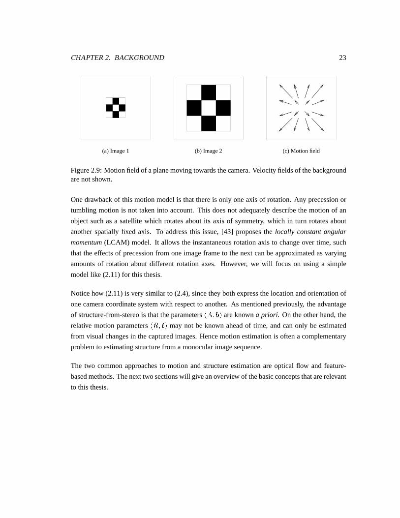
(a) Image1 (b) Image2 (c) Motion field
Figure2.9: Motion field of aplanemoving towardsthecamera.Velocityfieldsof thebackgroundarenot shown.
Onedrawbackof this motionmodelis that thereis only oneaxisof rotation.Any precessionor
tumblingmotion is not taken into account.This doesnot adequatelydescribethemotion of an
objectsuchasa satellitewhich rotatesaboutits axis of symmetry, which in turn rotatesabout
anotherspatiallyfixed axis. To addressthis issue,[43] proposesthe locally constantangular
momentum(LCAM) model. It allows the instantaneousrotationaxis to changeover time, such
that theeffectsof precessionfrom oneimageframeto thenext canbeapproximatedasvarying
amountsof rotation aboutdifferent rotation axes. However, we will focus on using a simple
modellike (2.11)for this thesis.
Noticehow (2.11)is very similar to (2.4),sincethey bothexpressthelocationandorientationof
onecameracoordinatesystemwith respectto another. As mentionedpreviously, theadvantage
of structure-from-stereois that theparametersZ()�v*#� areknown a priori . On theotherhand,the
relative motion parametersZd¡�Z "� may not be known aheadof time, andcanonly be estimated
from visualchangesin thecapturedimages.Hencemotionestimationis oftena complementary
problemto estimatingstructurefrom amonocularimagesequence.
The two commonapproachesto motion andstructureestimationareoptical flow andfeature-
basedmethods.Thenext two sectionswill giveanoverview of thebasicconceptsthatarerelevant
to this thesis.
CHAPTER2. BACKGROUND 24
2.5.2 Motion and Structure From Optical Flow
Whenacamerais moving with respectto anobject,theapparentchangein theimagepositionof
aprojectedpoint, <¤Z��� , canbeexpressedasa two dimensionalvelocityvector
¥ � ¢���¦x¢_�¢���¦x¢��
A collectionof thevelocityvectorsfor differentpointsin thesceneformsthemotionfield [2]. An
exampleof themotionfield for amoving planeis illustratedin Figure2.9.Analysisof themotion
field inducedby two consecutive imagescanbeusedto estimatestructureof thescene.Without
actuallyknowing theunderlyingmotion,themotionfield ontheimagescannotbeknown exactly
but hasto beestimated.Theestimateis referredto asoptical flow [44, 45, 46].
Many differentialtechniquesfor estimatingmotionfield havebeenproposedin thepast[44, 45];
they examinethetemporalchangesin thebrightnesspatternof images.Let §¨��Q��������� betheimage
brightnesspattern,or thelight intensityat thepoint ��Q����� of theimageplaneat time � . Thenthe
first orderapproximationof its changeover time is
¢�§¢���ª© §© � ¢��¢��
8 © §© � ¢��¢��8 © §© � :
Oneassumptioncritical to theestimationof opticalflow is thatundertheLambertianmodelof
lighting, thebrightnessof apoint in thesceneremainsconstantover time. Theresultis theimage
brightnessconstancy equation[1]:
¢�§¢_�� N �
which impliesthat
© §© � ¢_�¢_�8 © §© � ¢_�¢��
8 © §© �� N
or,
Z«7§¨� 1 ¥ 8 §x¬ � N (2.12)
CHAPTER2. BACKGROUND 25
where «7§ is thefirst orderspatialgradientof § , and§x¬ is thetemporalderivative.
Since(2.12)containsonly oneindependentvariable,§ , andthemotionfield ¥ hastwo compo-
nents,¥ cannotbeestimatedusing§ atasinglescenepoint. Additionalconstraintsarenecessary.
For example,Horn andSchunck[44] asserta smoothnessconstraint,which makestheassump-
tion that themotionfield variessmoothlyalmosteverywherein the image.Mayhew andFrisby
[5] lists several constraintsproposedby otherresearchers,suchasthe assumptionsthatmotion
field is constantor varieslinearlyoveraregionof theimage,andthatthesecondorderderivatives
of § arealsoconstant.
The estimationof the motion field is analogousto solving the featurecorrespondenceproblem
betweentwo imageframes,becausefor eachpoint < Y Z��� onanimage,theestimatedmotionfield
providesanestimateof thelocationof < Y Z� 8 � � . However, sincethethree-dimensionalmotion
parametersareunknown, motionhasto beestimatedat thesametime, resultingin anestimation
problemwith moreunknownsandlessconstraintsthanthestructure-from-stereoproblem.
Usingtheperspective projectionequationsin (2.1),theapparentmotionof apointona2D image
canbeexpressedasa functionof thepoint’s actualthree-dimensionalinstantaneousvelocity. In
components,
� C � ��� �� { ���� �
� E � ��� ��� { � ���� : (2.13)
By substituting(2.10)andconsequently(2.1) into (2.13),two equationscanbederived:
� C � B C � ��®� { ��� � ��8 B C � �¯®� ®�
���{ B C � ��®�
���{ ��� � � 8 B C � ��®�
� E � B E ��� ®� { ��� ����
{ B C � ��®� ®����
8 B C � �)®� ���
8 ��� �°�±{ B²C �u� ®� (2.14)
where
®� � � { � � ®� � � { � :
Additional constraintssuchasobjectsurfacesmoothnessandrestrictedmotion arerequiredto
CHAPTER2. BACKGROUND 26
direction of spatial gradient
vv
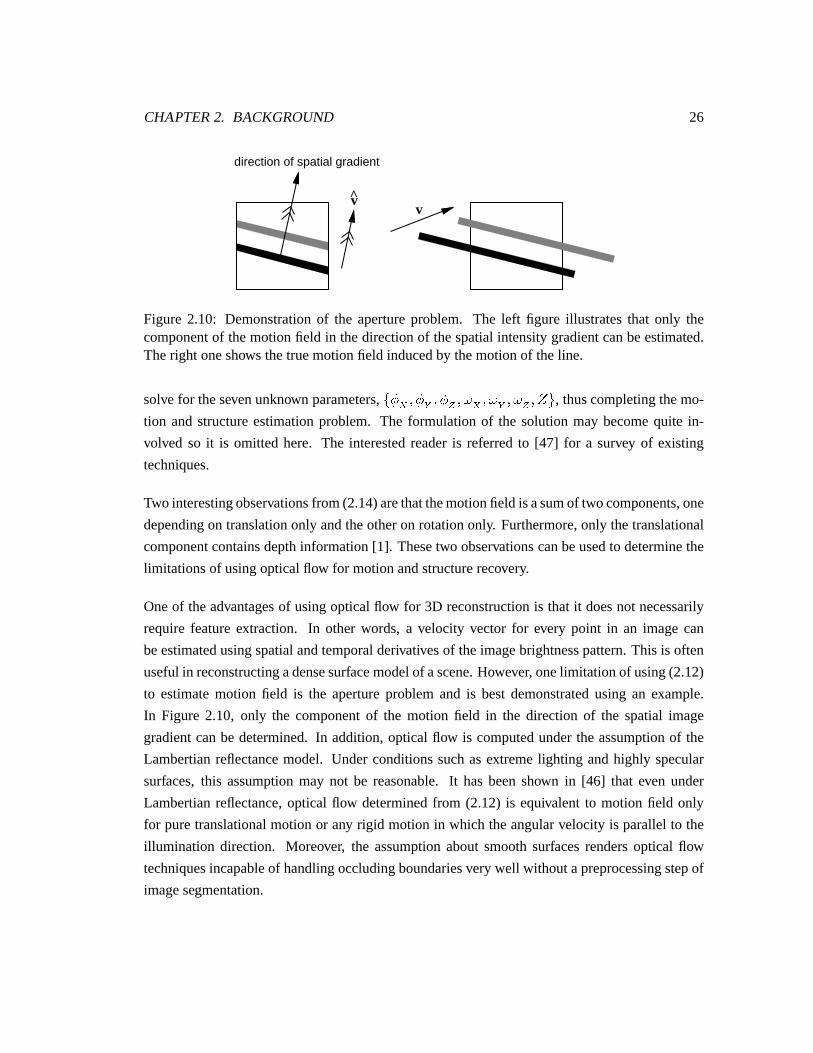
Figure 2.10: Demonstrationof the apertureproblem. The left figure illustratesthat only thecomponentof themotionfield in thedirectionof thespatialintensitygradientcanbeestimated.Theright oneshows thetruemotionfield inducedby themotionof theline.
solve for thesevenunknown parameters,X � � � � � � � � � � � � � � � � � ���7[ , thuscompletingthemo-
tion andstructureestimationproblem. The formulationof the solutionmay becomequite in-
volved so it is omittedhere. The interestedreaderis referredto [47] for a survey of existing
techniques.
Two interestingobservationsfrom(2.14)arethatthemotionfield isasumof twocomponents,one
dependingon translationonly andtheotheron rotationonly. Furthermore,only thetranslational
componentcontainsdepthinformation[1]. Thesetwo observationscanbeusedto determinethe
limitationsof usingopticalflow for motionandstructurerecovery.
Oneof theadvantagesof usingopticalflow for 3D reconstructionis that it doesnot necessarily
requirefeatureextraction. In other words, a velocity vector for every point in an imagecan
beestimatedusingspatialandtemporalderivativesof theimagebrightnesspattern.This is often
usefulin reconstructingadensesurfacemodelof ascene.However, onelimitation of using(2.12)
to estimatemotion field is the apertureproblemand is bestdemonstratedusing an example.
In Figure 2.10, only the componentof the motion field in the direction of the spatial image
gradientcanbe determined.In addition,optical flow is computedunderthe assumptionof the
Lambertianreflectancemodel. Underconditionssuchasextremelighting andhighly specular
surfaces,this assumptionmay not be reasonable.It hasbeenshown in [46] that even under
Lambertianreflectance,optical flow determinedfrom (2.12) is equivalent to motion field only
for puretranslationalmotionor any rigid motion in which theangularvelocity is parallelto the
illumination direction. Moreover, the assumptionaboutsmoothsurfacesrendersoptical flow
techniquesincapableof handlingoccludingboundariesverywell withoutapreprocessingstepof
imagesegmentation.
CHAPTER2. BACKGROUND 27
2.5.3 Motion and Structure From Point Features
Thesecondcategoryof structure-from-motionmethodsis feature-based.Similar to feature-based
stereomatching,discretefeaturesin amotionsequencehave to beextractedfrom theimagesand
thecorrespondenceproblemhasto solvedexplicitly. In structure-from-motion,featurematching
is to establishtemporalcorrespondingpairs X�< Y Z���Z�Z< Y Z� 8 � �Z[ . Again, for the time being,
we will assumethat featurecorrespondenceshave alreadybeenestablishedandfirst discussthe
structureestimationaspectof thereconstructionproblem.
Sincethe recovery of structureis coupledwith motion estimation,therearetwo differentcate-
goriesof algorithmsdependingon whetherstructureor motion is determinedfirst. An example
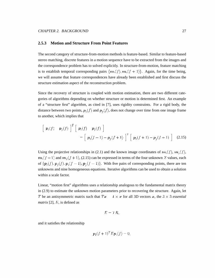
of a “structurefirst” algorithm,ascited in [7], usesrigidity constraints.For a rigid body, the
distancebetweentwo points,+ Y Z��� and +�³vZ��� , doesnot changeover time from oneimageframe
to another, which impliesthat
+ Y Z��� { +�³�Z��� 1 + Y Z��� { +�³vZ���� + Y Z� 8 � � { + ³ Z� 8 � � 1 + Y Z� 8 � � { + ³ Z� 8 � � (2.15)
Using theprojective relationshipsin (2.1) andtheknown imagecoordinatesof < Y Z��� , < ³ Z��� ,< Y Z� 8 � � and < ³ Z� 8 � � , (2.15)canbeexpressedin termsof thefour unknown � values,each
of X�+�Y�Z���Z�Z+ ³ Z���Z�Z+�Y´Z� 8 � �Z�Z+ ³ Z� 8 � �Z[ . With five pairsof correspondingpoints,thereareten
unknownsandninehomogeneousequations.Iterativealgorithmscanbeusedto obtainasolution
within ascalefactor.
Linear, “motion first” algorithmsusesa relationshipanalogousto thefundamentalmatrix theory
in (2.9) to estimatetheunknown motionparametersprior to recovering thestructure.Again, letµbe an antisymmetricmatrix suchthat
µ � � �&�� for all 3D vectors� , the %¶&·% essential
matrix [2], � , is definedas
� � µ d¡�andit satisfiestherelationship
+ Y Z� 8 � � 1 �¯+ Y Z��� � N �
CHAPTER2. BACKGROUND 28
aswell as
o< Y Z� 8 � � 1 � I y 1b � < Y Z���� I y�za � N (2.16)
Thenineunknown parametersin � arethenestimatedby usingeightpairsof imagepoint corre-
spondences.Consequently, themotionparametersd and� , aswell asthedepthvaluesof thepoint
features,canberecoveredwithin ascalefactor. Referto [8, 7] for thedetailsof thealgorithmand
asurvey of otherfeature-basedtechniques.
2.5.4 Long Image Sequences
Onecommonaspectbetweenoptical flow andfeature-basedtechniquesfor recovering motion
andstructureasdiscussedso far is that only two imageframesareconsidered.As mentioned
earlier, the baselinebetweenthe camerasin a monocularsequenceis relatively small. The re-
sultingmotionandstructureestimatesfrom two views alonemaybevery sensitive to noiseand
inaccurate.Thereforesomeof theresearchin this areaconcentrateson erroranalysisandusing
morethantwo imagesfrom amonocularsequenceto improve robustness[9, 48, 49].
Anotherdirectionof researchis to usealongimagesequence;generallytherearetwo approaches:
batchandrecursive. Thebatchapproachassumesthatall theimagesof avery long sequenceare
readilyavailableat oncesothatmoredatais available,reducingtheeffectsof noiseandoutliers
on themotionandstructureestimates.An exampleis thefactorizationmethodin [21] andother
relatedwork [23, 50]. Therecursive approachfocuseson iteratively refiningtheaccuracy of ini-
tial motion andstructureestimatesasmoreimageframesareavailable. Someexamplesin this
category are[51, 52, 53, 54]. Amongthoseusingthelatterapproach,theapplicationof Kalman
filtering [55] for dynamicstateestimationis commonbecauseit explicitly incorporatesan un-
certaintymodelandintegratesnew measurements(e.g. positionsof featurepoints)to iteratively
refinecurrentestimatesof structureandmotion.
Whenprocessinglong imagesequences,theproblemof featurecorrespondenceis no longerlim-
ited to finding matchesbetweena singlepair of imageframes,but is to locatethesamefeatures
over many frames. The small camerabaselinein a motion sequenceallows featureson an im-
ageto be tracked over time becausetheir appearanceaswell astheir positionson the imagedo
CHAPTER2. BACKGROUND 29
not changevery muchfrom oneframeto thenext. Featurepoint trackingalgorithmsmayutilise
opticalflow techniques,suchasthosein [56, 57], to computevelocityfieldsusingspatialandtem-
poral imagegradients,or mayapplya smoothnessconstrainton themotion to establishsmooth
trajectoriesassumingthatall theimageframesareavailableat once[58, 59]. Techniquesdevel-
opedfor trackingmultiple targetsin radarimagery[60] have alsobeenextendedsuccessfullyto
establishmotioncorrespondencesin imagesequences[61, 62, 63, 64].
2.5.5 Advantagesand Disadvantages
Comparedto stereocorrespondence,the problemof motion correspondenceis easierto solve.
Tracking techniquescanmuch more reliably establishfeaturematchesbetweenimageframes
thanstereomatching.Unfortunately, thestructureestimatedusingtwo framesaloneis verynoise
sensitive and inaccurate.Batch processingof long sequencescan combatthis problembut it
requiresthat all of the imagesbe availableat the time of processing.This may not be an ideal
solutionfor thefollowing reasons:
1. Assumptionslike constantmotionmaybeviolatedoversucha longsequence;
2. Batchprocessingimposesheavy datastoragerequirementsfor retaininginformationon
many images;
3. Motion andstructurecanonly beestimatedafterall theimagesareavailable.
For thesereasons,theideaof recursively refiningmotionandstructureestimatesasmoreimages
becomeavailableseemsto be the mostviable solution. However, thereremainsthe drawback
that 3D reconstructionfrom motion without knowing the magnitudeof the relative translation
betweenthecameraandthescene,thedepthsof objectpointscannotbedeterminedexactly, but
only within a global scalefactor. For example,if oneobject is two timesasfar asanother, but
twiceasbig, andit is translatedat twice thespeed,theresultingimagesof thetwo objectswould
be exactly the same. This characteristicmay not be problematicfor an applicationlike object
recognition,but would definitelybea concernfor applicationsin which theabsolutelocationof
objectsrelative to thecamerais desired,suchasthecomputervisionguidedgraspingof satellites
in outerspace.
CHAPTER2. BACKGROUND 30
2.6 Structure fr om StereoImage Sequences
Theshortcomingsof bothstructure-from-stereoandstructure-from-motiontechniquesfor 3D re-
construction,asdescribedin the previous sections,have motivateda new directionof research
for the integrationof bothstereoandmotion informationin developing3D reconstructionalgo-
rithms.While featurecorrespondenceis adifficult taskfor stereo,it is relatively easyfor motion,
but stereoprovidesbetterstructureestimates.Theadvantageof integratingbothstereoandmo-
tion is thatthey cancomplementeachotherto overcometheir individual weaknesses.
A commonimageacquisitionsystemfor this approachincludesa setof stereocamerasmounted
onaplatformor roboticarm.Eitherthecamerasor theobjectsin thesceneor bothundergo some
form of motion. This set-upprovides a sequenceof stereoimagepairs, X �Za Z���Z� �Zb Z���Z[ , that
vary over time. Many of theproposedmethodsin this areaincorporatevariouscombinationsof
existing techniquesfrom bothof thetraditionalapproachesof stereoandmotion.Thedifferences
amongthemgenerallydependon thefollowing factors:
1. thedegreeto which theuseof themotionassistsin stereomatching,
2. theway in which thisassistanceis providedif any, and
3. how theuseof thestereosequenceimprovesstructureestimates.
Wewill discusstheseaspectsamongthreebroadcategoriesof pastresearchin thisarea.
2.6.1 AssumedFeature Corr espondences
Someof thework on usingstereoimagesequencesassumethataccuratestereocorrespondences
have alreadybeenestablishedby someexternalprocess.The focusof this groupof work is to
usetheaddedmotioninformationto improve or refinemotionanddepthestimates.Like similar
work doneusingmonocularsequences,MatthiesandKanade[65] employ the Kalmanfilter to
recursively refinestructureestimatesusingknown motion. Accuratestereocorrespondencesor
a 3D representationof the sceneareassumedto be available initially. The differencebetween
this andthemonocularsequenceapproachis that 2D measurementsarenow madeon both the
left andright imagestreams.Motion correspondencesareestablishedimplicitly throughKalman
filter tracking.Detailson theformulationwill beprovidedin Chapter3 of this thesis.
CHAPTER2. BACKGROUND 31
AyacheandFaugeras[66] appliedthesametechniques,payingspecialattentionto how depthun-
certaintiesof differentgeometricfeaturesarepropagated.In additionto refiningdepthestimates,
they alsodiscussaboutrefiningmotionestimates,by using3D pointcorrespondencesestablished
betweentwo pairsof stereoframes.YoungandChellappa[67] takeanextrastepandassumethat
bothstereoandmotioncorrespondencesareestablished,suchthat themeasurementsarereadily
3D featurepoints.Thefocusof their work is to iteratively refinemotionanddepthestimates.
Someother researchers,like Navab et. al. [10], aremainly interestedin the useof combining
stereoandmotionto assistin motionestimation,since3D point or line motioncorrespondences
provide moreaccurate,uniquemotionestimates.
2.6.2 Dir ectEstimation or Inference
In this classof 3D reconstructionalgorithms,theadditionalconstraintsprovidedby bothmotion
andstereoareuseddirectly to computeor infer thelocationof stereocorrespondences.
Onecommontechniqueis to applyopticalflow to stereoimagesequences.In Section2.5.2,we
have seenhow optical flow techniquescanbe usedto estimateapparentmotion and therefore
the structureof a sceneor object from a pair of imagesin a motion sequence.Shi et. al. [68,
11, 69]have extendedthe imagebrightnessconstancy constraintto stereoimagepairs,andthey
referredto this as unifiedoptical flow field (UOFF). In summary, they assumethat the image
brightnessof a point in thescenenot only remainsconstantover time, it alsoremainsconstant
from onecameraviewpoint to another. Theimagebrightnesspatternin this formulationbecomes
a functionof four parameters:
§ � §!����������L��]$�Z�where� and � in this caserefersto the imagelocationof a point in thescene,which in turn are
functionsof � , time, and ] , the viewpoint. Using c and d asthe viewpoints, brightnesstime
invarianceimpliesthat
§¨��Q��L��c��Z���������c¸�Z������c¸� � §¨��Q�� 8 � ��c¸�Z������ 8 � ��c¸�Z��� 8 � ��c��Z� (2.17)
CHAPTER2. BACKGROUND 32
andbrightnessspaceinvarianceimpliesthat
§¨��Q��L��c��Z���������c¸�Z������c¸� � §¨��Q��L��d¡�Z���������d¡�Z���L��d¡�Z: (2.18)
Combining(2.17)and(2.18)givesthetime andspaceinvarianceconstraint:
§¨��������c¸�Z������L��c��Z���L��c�� � §¨����� 8 � ��d¡�Z������ 8 � ��d¡�Z��� 8 � ��d¡�Usingthis constraint,opticalflow quantitiesarecomputedacrossbothtime andviewpoint using
any establishedoptical flow techniquessuchas thosementionedin Section2.5.2. Along with
the optical flow quantitiescomputedusing (2.17) and (2.18), the motion andstructurecanbe
estimatedfrom asystemof equations.
SteinandShashua[12] usethe samebrightnessconstancy assumptionto first establishcorre-
spondencesfor both point and line features,andthenappliedrigidity andepipolarconstraints
to estimatemotionandstructure.Realisingthat this is a strongassumptionfor imagescaptured
from largely varyingviewpoints,they usedacoarseto fineapproachto processtheimages.
Another interestingexamplewhich directly infers stereocorrespondencesfrom imagedatais
[13], andit is built on thefactorizationmethod[21] for processingmonocularsequences.Stereo
geometryis addedto the formulationof the problem. The methodstill hasa batchapproach,
requiringall imagesto beavailableatthetimeof processing,but theauthorsshow thatthenumber
of framesrequiredfor reasonablyaccuratestructureestimatesusingthestereo-motionapproach
is muchlessthanthatof usingmotionalone.
2.6.3 ConstrainedMatching
In both traditional structure-from-stereoand structure-from-motiontechniques,featurecorre-
spondencesestablishedbetweena singlepair of stereoor temporalimagesarenot necessarily
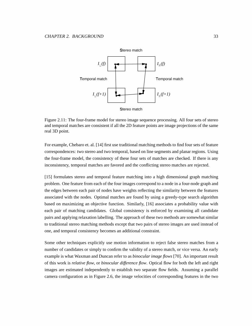
correct.A commonformulationfor constrainedmatchingis to useamodelconsistingof thefour
imageframes,X �Za Z���Z� �Zb Z���Z� �Za Z� 8 � �Z� �Zb Z� 8 � �Z[ , asin Figure2.11.Thestructuralinformation
derivedfrom any combinationof thesefour imagesshouldbeconsistent.Thisconsistency canbe
usedto bootstrapthe featurematchingprocess,or provide additionalstructuralinformationnot
availablein asinglepairof stereoimages.
CHAPTER2. BACKGROUND 33
I (f+1)L I (f+1)R
I (f)L I (f)R
Temporal match¹
Stereo matchº
Stereo matchº
Temporal match¹
Figure2.11:Thefour-framemodelfor stereoimagesequenceprocessing.All four setsof stereoandtemporalmatchesareconsistentif all the2D featurepointsareimageprojectionsof thesamereal3D point.
For example,Chebaroet.al. [14] first usetraditionalmatchingmethodsto find four setsof feature
correspondences:two stereoandtwo temporal,basedon line segmentsandplanarregions.Using
thefour-framemodel,theconsistency of thesefour setsof matchesarechecked. If thereis any
inconsistency, temporalmatchesarefavoredandtheconflictingstereomatchesarerejected.
[15] formulatesstereoandtemporalfeaturematchinginto a high dimensionalgraphmatching
problem.Onefeaturefrom eachof thefour imagescorrespondto anodein afour-nodegraphand
theedgesbetweeneachpair of nodeshave weightsreflectingthesimilarity betweenthefeatures
associatedwith thenodes.Optimalmatchesarefoundby usinga greedy-typesearchalgorithm
basedon maximizingan objective function. Similarly, [16] associatesa probability valuewith
eachpair of matchingcandidates.Global consistency is enforcedby examiningall candidate
pairsandapplyingrelaxationlabelling.Theapproachof thesetwo methodsaresomewhatsimilar
to traditionalstereomatchingmethodsexceptthat two pairsof stereoimagesareusedinsteadof
one,andtemporalconsistency becomesanadditionalconstraint.
Someother techniquesexplicitly usemotion informationto reject falsestereomatchesfrom a
numberof candidatesor simply to confirmthevalidity of astereomatch,or vice versa.An early
exampleis whatWaxmanandDuncanreferto asbinocularimageflows[70]. An importantresult
of this work is relativeflow, or binoculardifferenceflow. Opticalflow for boththeleft andright
imagesareestimatedindependentlyto establishtwo separateflow fields. Assuminga parallel
cameraconfigurationasin Figure2.6, the imagevelocitiesof correspondingfeaturesin thetwo
CHAPTER2. BACKGROUND 34
camerasaredenotedby ¥ t �� t ��� t � and ¥ w �� t 8¼» ��� t � , where»
is thedisparity. Relative flow
is thenthedifferencebetweenthesetwo quantities,thatis,
½ ¥ t6��St¾���¨t6� » � � ¥ w!��Qt 8F» ���¨t¿� { ¥ t6��Qt����¨t¾�andcanbeexpressedasa functionof therigid motionparametersof thecamera,
½ ¥ t6��Qt¾���¨t�� » � � � � � � » 8 ��¨t � � { �St � � � » �½ � t6��Qt¾���¨t�À » � � N : (2.19)
The authorsdemonstratedthat by using theseconstraints,only two componentsof the overall
motion facilitatein stereomatching:� �
and� �
. For a featurelocatedat ��Qt����¨t6� , the correct
matchin� b
shouldsatisfytherelationshipsin (2.19),therefore(2.19)canbeusedto estimate»
directly or to rejectunlikely candidates.Oneassumptionusedin theexperimentsshown is that
themotionof thecamerais known.
Anothermethodusingopticalflow is [17]. Thealgorithmfirst determinesthedepthsof detected
featurepointsby usingoptical flow techniqueson bothof the left andright imagestreamssep-
arately, obtainingtheestimatedquantities� a and � b . Thenfeaturepointsin the left andright
imagesarematchedagainsteachother. For a stereomatchto be correct,the calculateddepth
from thedisparityvaluemustbeconsistentwith thevaluesestimatedby theleft andright optical
flow fields,thatis, assertingthat � a � � b � �ÂÁ .
Matthiesusesa three-framemodel [18]. A densedepthmap is first developedusing closely
sampledimages,suchas�Za Z��� and
�Za Z� 8 � � . This depthmap is thenusedto constrainthe
determinationof the disparitymap between�Za Z� 8 � � and
�Zb Z� 8 � � . Matching is doneby
correlationandlimited a priori motioninformationis available.
Both [19] and[20] arerecursive algorithmsthatusemultiple hypothesistestingtechniquesand
motionconstraintsto validatestereomatchingcandidates.JenkinandTsotsos[19] initialise their
algorithmby assumingasetof accuratestereocorrespondencesin thefirst imagepair, andstereo
matchingin the future framesareconstrainedby the predictedlocationsof theseinitial feature
points.By usingmultiplehypothesistracking,theresolutionof ambiguitiesin temporalmatching
is delayed.Yi andOh [20], on theotherhand,doesnotassumeaccuratestereocorrespondences.
Virtual 3D tokensaregeneratedfrom pairsof stereomatchingcandidatesandKalmanfiltering
CHAPTER2. BACKGROUND 35
is usedto predict their locationsthroughthe stereosequence.The motion of incorrectstereo
matcheswill not conformto the predictedpathsandhencecanbe rejected. In this work, it is
assumedthat the sceneis composedof objectsmoving in differentdirectionsand they are far
enoughfrom the camerasthat they arerepresentedas individual point featureson the images.
Their motion is approximatedby puretranslation,therefore,it is simpleenoughto includethe
motion parametersin the statevectorto be estimated.This formulationhasthe advantagethat
motionestimatescanbeautomaticallyupdatedby theKalmanfilter.
2.6.4 Summary
The use of a stereoimage sequencefor 3D reconstructionprovides the advantagesof both
structure-from-stereoandstructure-from-motiontechniques.Wehaveseenmany innovativeideas
onhow stereo-motioncanbeintegratedto assistin thetask;however, noneof themfully satisfies
thespecificdemandsof theproblemwe aretrying to solve.
Somemethodssimply assumethat the featurecorrespondenceis solved. However, for a com-
plete3D reconstructionsolution,it is insufficient to assertthisassumption.Theinherentproblem
in applyingoptical flow techniquesfor stereocorrespondenceis that the imagebrightnesscon-
stancy assumptionmost likely doesnot hold in the lighting conditionsin space. As we have
seenin Figure1.1, the changesin the lighting andshadows causethe samephysicalpoints to
look very differentfrom frameto frame.For a free-floatingobjectin space,thesceneis dynamic
andmotion is involved. The problemof usingbatchprocessingof the stereosequencein this
context is thatanupdated3D representationwould only beavailableat theendof a long period.
However, for suchtasksasvision-guidedposeestimation[71, 72], a recursive approachwould
bemoreappropriate.Mostconstrainedmatchingmethodsuseafeature-basedapproach,andthey
explicitly takeadvantageof bothstereoandmotioninformationto constrainthefeaturematching
problem. This is a promisingdirection,but thereis a lack of existing methodsthataddressthe
specificissuesof reconstructingasinglerigid bodyundergoingunknown motion.
All theseshortcomingssuggestthat thereis a needfor finding a new, unified framework for an
algorithmthatwould take advantageof bothstereoandmotioninformation.
Chapter 3
Incr emental3D Reconstruction
In this chapter, we definein detailsthespecific3D reconstructionproblemthatwe areinterested
in solving,andidentify theaspectsof theproblemthat this thesiswill examine.An incremental
3D reconstructionalgorithmthat incorporatesboth pastandnew researchideasfor solving this
problemis proposed.Thebasiccomponentsof thealgorithmwill bediscussed.
3.1 ProblemDefinition
The goalof the researchin this thesis,asmentionedin Chapter1, is to develop an algorithmic
framework for recoveringdepthinformationaboutobjectsin ascenefrom 2D digital images.The
3D informationmaybeusedwith theresultsof othercomputervision tasksfor applicationssuch
astheaerospaceapplicationin whichMDR holdsinterest.
After examiningthedifferentaspectsof theproblemandthepastresearchin Chapter2 on3D re-
construction,ourresearchwill focusondevelopinganincremental3D reconstructionalgorithm
with thefollowing characteristics:
� thereconstructionis basedon extractedfeatures;
� astereoimagesequenceis used;
36
CHAPTER3. INCREMENTAL 3D RECONSTRUCTION 37
� featurematchingis addressedexplicitly;
� thesystemacquiresanincrementallydenseandaccuraterepresentationof thereconstructed
objectby bootstrappingfeaturematchingandmotionestimation.
Wewill now discusseachaspectin moredetailbelow:
Feature-based: As mentionedin Chapter1, the environmentof outer spaceimposesspecific
challengesfor 3D reconstructionalgorithms.For example,theextremelighting conditions
renderinappropriatetechniquessuchasopticalflow or any methodsthathighly rely on the
assumptionof imagebrightnessconstancy. Theuseof extractedfeaturesmayalleviatethis
problemandis themoresensiblein orderfor thework of this thesisto beapplicablein the
futureto spaceapplications.
Stereoimagesequence:Wehaveseenin Section2.6thattheuseof astereosequencecanover-
comethe individual weaknessesof eitherusingstereoor motionmethodsalone.This is a
worthwhiledirectionto pursuein ourown investigation.
Feature matching: The featurecorrespondenceproblem,definedin Section2.2, is the most
challengingproblemfor 3D reconstruction,andstill remainsto besolved. We would like
to furtherexplorethisproblemin thecontext of astereoimagesequence.
Incremental: The quality of the imagesavailable at any short periodof time may not afford
a goodreconstructiondue to the lack of pertinentvisual informationor the difficulty of
featureextractionin somecircumstances.Along with the difficulty of the featurecorre-
spondenceproblemitself, sometimestheamountof depthinformationavailablefrom afew
framesis not sufficient for providing overall structureof objects.Theability to integrate
structuralinformationover a long sequenceof stereoimageswould be a desiredcharac-
teristic of the algorithm. Using this approach,it would alsobe unnecessaryto solve the
problemof stereocorrespondencefully at any time frame,asambiguitiescanberesolved
over time.
Oneof theareasin which a well definedframework seemsto be lacking in pastresearch
is on how a stereoimagesequencecanbe usedefficaciouslyto bootstrapfeaturematch-
ing andmotion estimationsimultaneouslywhenboth structureandmotion areunknown.
Therefore,this thesiswill primarily focuson thisaspect.
CHAPTER3. INCREMENTAL 3D RECONSTRUCTION 38
Beforewediscussthedetailsof theproposedalgorithm,thescopeandassumptionsof thecurrent
researchwill beoutlinedasfollows:
Features: In Section2.3, the advantagesof usingpoint featuresover otherssuchas lines and
ellipsesarediscussed.Becauseof thoseadvantages,our researchwill focusonusingpoint
featuresandreconstructing3D points.However, no restrictionsareimposedonthekind of
point featuresthatwe use.
Object representation: Theproblemof surfaceinterpolationfrom asetof scattereddatapoints
is a completelydifferentresearchtopic on its own, thereforeit is outsidethescopeof this
thesis.We will limit ourselvesto reconstructing3D pointsthatcorrespondto geometrical
or textural featureson a rigid objectin thescene.We will alsonot concernourselveswith
therelationshipsamongthesepointsfrom apoint-patternperspective.
Motion: In order to keepour motion model as simple as that describedin Section2.5, it is
assumedthat thereis a single,unknown rigid relative motionbetweenthecameraandthe
object. Themotion is eitherconstantor varyingslowly sothat theeffectsof time-varying
motion are not realizedover short sequenceof frames. The motion must also follow a
smoothtrajectory.
The reasonwhy the proposedalgorithmwill not considerwhat kind of point featuresareused
is becauseour matchingalgorithmdoesnot rely on any visual informationor specificattributes
aboutthesefeatures. We are interestedin investigatingfeaturematchingbasedsolely on the
locationsof the features,andthe rigidity andrelative motion of the object. The advantagesof
thispostulationis thatwedonothave to beconcernedaboutwhatinformationis providedby the
specificfeatureextractorwe use,or whatlocal matchingalgorithmwe shoulduse.
3.2 Overview of the Incr ementalReconstructionAlgorithm
As mentionedin Chapter2, theminimal changesbetweensuccessive imagesin a monocularse-
quencepermittemporalfeaturecorrespondencesto beestablishedeffectively by meansof feature
tracking[56, 57, 61, 62, 63, 64]. In theproposedalgorithm,we will usewell establishedtech-
niquesto performthis task. However, sincewe arealso interestedin taking advantageof the
stereoinformationprovidedby astereosequence,thefeaturetrackingalgorithmwill bemodified
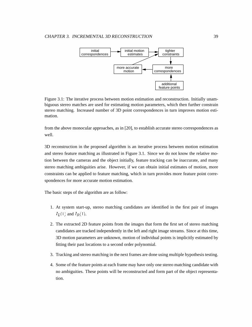
CHAPTER3. INCREMENTAL 3D RECONSTRUCTION 39
initialcorrespondences
tighterconstraints
initial motion estimates
additionalfeature points
morecorrespondences
more accurate motion
Figure3.1: Theiterative processbetweenmotionestimationandreconstruction.Initially unam-biguousstereomatchesareusedfor estimatingmotionparameters,which thenfurtherconstrainstereomatching. Increasednumberof 3D point correspondencesin turn improvesmotion esti-mation.
from theabovemonocularapproaches,asin [20], to establishaccuratestereocorrespondencesas
well.
3D reconstructionin the proposedalgorithmis an iterative processbetweenmotion estimation
andstereofeaturematchingasillustratedin Figure3.1. Sincewe do not know the relative mo-
tion betweenthe camerasandthe objectinitially, featuretrackingcanbe inaccurate,andmany
stereomatchingambiguitiesarise. However, if we canobtaininitial estimatesof motion,more
constraintscanbeappliedto featurematching,which in turn providesmorefeaturepoint corre-
spondencesfor moreaccuratemotionestimation.
Thebasicstepsof thealgorithmareasfollow:
1. At systemstart-up,stereomatchingcandidatesare identified in the first pair of images�Za � � and�Zb � � .
2. Theextracted2D featurepointsfrom the imagesthat form thefirst setof stereomatching
candidatesaretrackedindependentlyin theleft andright imagestreams.Sinceat this time,
3D motionparametersareunknown, motionof individual pointsis implicitly estimatedby
fitting their pastlocationsto asecondorderpolynomial.
3. Trackingandstereomatchingin thenext framesaredoneusingmultiplehypothesistesting.
4. Someof thefeaturepointsateachframemayhaveonly onestereomatchingcandidatewith
no ambiguities.Thesepointswill bereconstructedandform partof theobjectrepresenta-
tion.
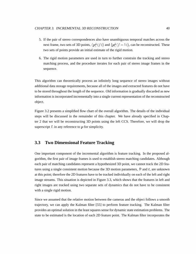
CHAPTER3. INCREMENTAL 3D RECONSTRUCTION 40
5. If thepair of stereocorrespondencesalsohave unambiguoustemporalmatchesacrossthe
next frame,two setsof 3D points, X�+ aY Z���Z[ and X�+ aY Z� 8 � �Z[ , canbereconstructed.These
two setsof pointsprovide aninitial estimateof therigid motion.
6. The rigid motion parametersareusedin turn to further constrainthe trackingandstereo
matchingprocess,andthe procedureiteratesfor eachpair of stereoimageframesin the
sequence.
This algorithm can theoreticallyprocessan infinitely long sequenceof stereoimageswithout
additionaldatastoragerequirements,becauseall of theimagesandextractedfeaturesdonothave
to bestoredthroughoutthelengthof thesequence.Old informationis graduallydiscardedasnew
informationis incorporatedincrementallyinto asinglecurrentrepresentationof thereconstructed
object.
Figure3.2presentsa simplifiedflow chartof theoverall algorithm.Thedetailsof theindividual
stepswill be discussedin the remainderof this chapter. We have alreadyspecifiedin Chap-
ter 2 that we will be reconstructing3D pointsusingthe left CCS.Therefore,we will drop the
superscriptc in any referenceto + for simplicity.
3.3 Two DimensionalFeatureTracking
Oneimportantcomponentof the incrementalalgorithmis featuretracking. In the proposedal-
gorithm,thefirst pair of imageframesis usedto establishstereomatchingcandidates.Although
eachpairof matchingcandidatesrepresentahypothesized3D point,we cannottrackthe2D fea-
turesusinga singleconsistentmotionbecausethe3D motionparameters,d and , areunknown
at thispoint; thereforethe2D featureshave to betrackedindividually oneachof theleft andright
imagestreams.This situationis depictedin Figure3.3,which shows that thefeaturesin left and
right imagesaretracked usingtwo separatesetsof dynamicsthat do not have to be consistent
with asinglerigid motion.
Sincewe assumedthattherelative motionbetweenthecamerasandtheobjectfollows a smooth
trajectory, we canapply the Kalmanfilter [55] to performfeaturetracking. The Kalmanfilter
providesanoptimalsolutionin theleastsquaressensefor dynamicstateestimationproblems.The
stateto beestimatedis thelocationof each2D featurepoint. TheKalmanfilter incorporatesthe
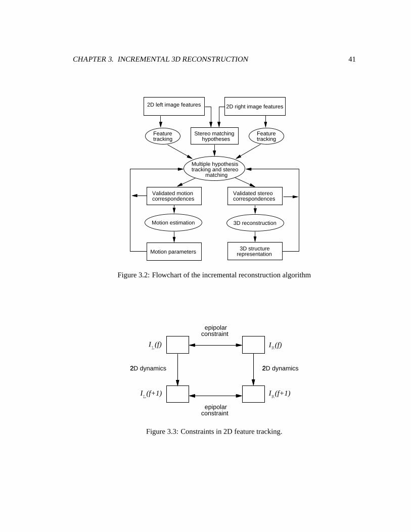
CHAPTER3. INCREMENTAL 3D RECONSTRUCTION 41
2D left image features 2D right image features
Stereo matching hypotheses
Featuretracking
Featuretracking
Validated stereocorrespondences
Validated motioncorrespondences
Motion estimation
Motion parameters
3D reconstruction
Multiple hypothesistracking and stereo matching
3D structurerepresentation
Figure3.2: Flowchartof theincrementalreconstructionalgorithm
epipolarconstraint
2D dynamicsÃ
2D dynamicsÃ
epipolarconstraint
I (f+1)L I (f+1)R
I (f)L I (f)R
Figure3.3: Constraintsin 2D featuretracking.
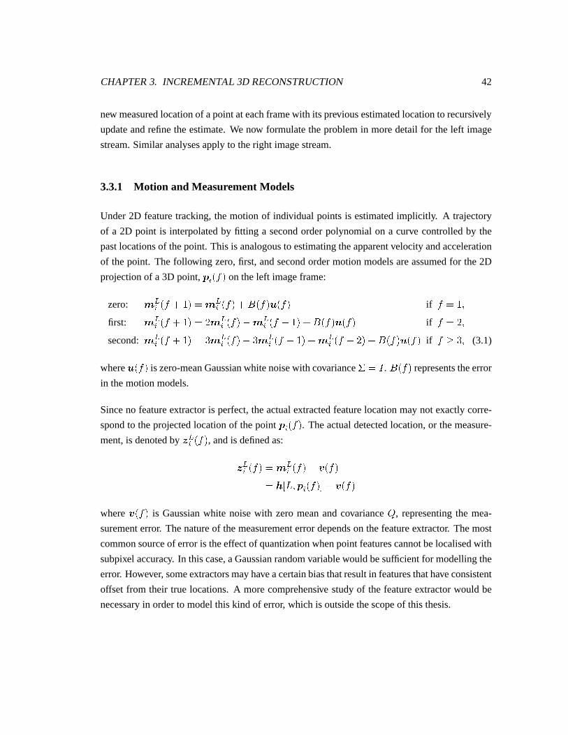
CHAPTER3. INCREMENTAL 3D RECONSTRUCTION 42
new measuredlocationof apointateachframewith its previousestimatedlocationto recursively
updateandrefinetheestimate.We now formulatetheproblemin moredetail for the left image
stream.Similar analysesapplyto theright imagestream.
3.3.1 Motion and MeasurementModels
Under2D featuretracking,themotion of individual pointsis estimatedimplicitly. A trajectory
of a 2D point is interpolatedby fitting a secondorderpolynomialon a curve controlledby the
pastlocationsof thepoint. This is analogousto estimatingtheapparentvelocityandacceleration
of thepoint. The following zero,first, andsecondordermotionmodelsareassumedfor the2D
projectionof a3D point, + Y Z��� on theleft imageframe:
zero: < aY Z� 8 � � � < aY Z��� 8 �ÄZ���oÅ`Z��� if � ��� �first: < aYÆZ� 8 � � � V�< aYÆZ��� { < aYÂZ� {F� � 8 �ÄZ���oÅ`Z��� if � � Vx�second: < aYÆZ� 8 � � � %�< aYÆZ��� { %�< aYÂZ� {·� � 8 < aYÆZ� { Vx� 8 �ÄZ���oÅ`Z��� if ��Ç�%x� (3.1)
whereůZ��� is zero-meanGaussianwhitenoisewith covarianceÈ �É� . �ÄZ��� representstheerror
in themotionmodels.
Sinceno featureextractoris perfect,theactualextractedfeaturelocationmaynot exactly corre-
spondto theprojectedlocationof thepoint + Y Z��� . Theactualdetectedlocation,or themeasure-
ment,is denotedby Ê aY Z��� , andis definedas:
Ê aYÂZ��� � < aYÆZ��� 8 ¥ Z���� ^ - c��Z+ Y Z����0 8 ¥ Z���where ¥ Z��� is Gaussianwhite noisewith zeromeanandcovariance
�, representingthe mea-
surementerror. Thenatureof themeasurementerrordependson thefeatureextractor. Themost
commonsourceof erroris theeffectof quantizationwhenpoint featurescannotbelocalisedwith
subpixel accuracy. In thiscase,aGaussianrandomvariablewouldbesufficient for modellingthe
error. However, someextractorsmayhaveacertainbiasthatresultin featuresthathaveconsistent
offset from their true locations.A morecomprehensive studyof the featureextractorwould be
necessaryin orderto modelthis kind of error, which is outsidethescopeof this thesis.
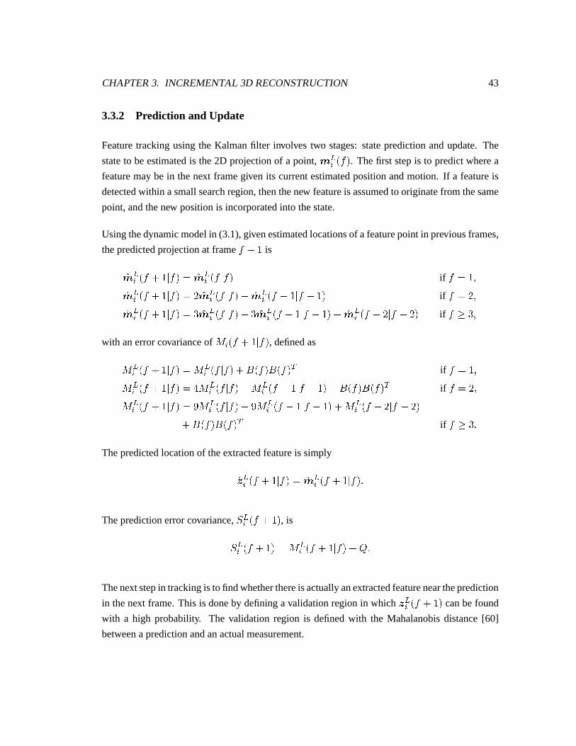
CHAPTER3. INCREMENTAL 3D RECONSTRUCTION 43
3.3.2 Prediction and Update
Featuretrackingusingthe Kalmanfilter involves two stages:statepredictionandupdate.The
stateto beestimatedis the2D projectionof a point, < aY Z��� . Thefirst stepis to predictwherea
featuremaybe in thenext framegiven its currentestimatedpositionandmotion. If a featureis
detectedwithin asmallsearchregion,thenthenew featureis assumedto originatefrom thesame
point,andthenew positionis incorporatedinto thestate.
Usingthedynamicmodelin (3.1),givenestimatedlocationsof afeaturepoint in previousframes,
thepredictedprojectionat frame � 8 � is
}< aYÆZ� 8 �¿Ë ��� � }< aYÂZ� Ë ��� if � �/� �}< aY Z� 8 �¿Ë ��� � V¶}< aY Z� Ë ��� { }< aY Z� {F�¿Ë � {F� � if � � Vx�}< aY Z� 8 �¿Ë ��� � %¶}< aY Z� Ë ��� { %¶}< aY Z� {F�¿Ë � {·� � 8 }< aY Z� { V Ë � { Vx� if ��Ç/%x�
with anerrorcovarianceof Ì Y Z� 8 �¿Ë ��� , definedas
Ì aY Z� 8 �¿Ë ��� � Ì aY Z� Ë ��� 8 �ÄZ���Z�ÄZ��� 1 if � ��� �Ì aY¯Z� 8 �¿Ë ��� �ÎÍ Ì aY'Z� Ë ��� { Ì aY'Z� {9�¿Ë � {F� � 8 �ÄZ���Z�ÄZ��� 1 if � � Vx�Ì aY¯Z� 8 �¿Ë ��� ��Ï Ì aY'Z� Ë ��� {FÏ Ì aY)Z� {9�¿Ë � {F� � 8 Ì aY¯Z� { V Ë � { Vx�8 �ÄZ���Z�ÄZ��� 1 if ��Ç�%x:
Thepredictedlocationof theextractedfeatureis simply
}Ê aYÆZ� 8 �¿Ë ��� � }< aYÂZ� 8 �¿Ë ���Z:
Thepredictionerrorcovariance,Ð aY Z� 8 � � , is
Ð aY¸Z� 8 � � � Ì aY¯Z� 8 �¿Ë ��� 8 � :
Thenext stepin trackingis tofindwhetherthereisactuallyanextractedfeatureneartheprediction
in thenext frame.This is doneby defininga validationregion in which Ê aY Z� 8 � � canbefound
with a high probability. The validation region is definedwith the Mahalanobisdistance[60]
betweenapredictionandanactualmeasurement.
CHAPTER3. INCREMENTAL 3D RECONSTRUCTION 44
Let ¢=Ñ��Ò���Ó²� representtheMahalanobisdistancebetween}Ê aYÂZ� 8 �¿Ë ��� andany extractedfeature
point Ê a³ Z� 8 � � in� a Z� 8 � � , then
¢ Ñ �ÒO��Ó²� ��- Ê a³ Z� 8 � � { }Ê aY Z� 8 �¿Ë ����0 1 Ð aY Z� 8 � � - Ê a³ Z� 8 � � { }Ê aY Z� 8 �¿Ë ����0 (3.2)
The extractedimagefeature Ê a³ Z� 8 � � is consideredto have originatedfrom }Ê aY Z� Ë ��� if the
condition
¢ Ñ �Ò���Ó6��ÔÎÕ (3.3)
is satisfied.Õ is determinedby thestatisticaldistribution of thepredictionandthelevel of confi-
dencethatis required.SinceÊ a³ Z� 8 � � and }Ê aY Z� 8 �¿Ë ��� haveGaussiandistributions,thedistance
in (3.2)hasa Ö distribution with two degreesof freedom.For a level of confidenceof 99%,we
canselecta thresholdÕ ��Ï :×V � N % .Graphically, (3.3)definesanelliptical region centeredaround }Ê aY Z� 8 �¿Ë ��� . Applying thestatis-
tical testto all extractedfeaturepointsin�Za Z� 8 � � is analogousto searchingfor all the feature
pointsthatareinsidethiselliptical region.
Assumingthat a particular point Ê a³ Z� 8 � � is found and is associatedwith the prediction
}Ê aY Z� 8 �¿Ë ��� , the new location and error covarianceof the featurepoint we are tracking can
beestimatedasfollow:
}< aY Z� 8 �¿Ë � 8 � � � }< aY Z� 8 �¿Ë ��� 8FØ aY Z� 8 � � - Ê a³ Z� 8 � � { }< aY Z� 8 �¿Ë ����0��Ì aY Z� 8 �¿Ë � 8 � � � Ì aY Z� 8 �¿Ë ��� { Ø aY Z� 8 � �ZÌ aY Z� 8 �¿Ë ���Z:
Ø aY Z� 8 � � is theKalmanfilter gain,where
Ø aY°Z� 8 � � � Ì aY)Z� 8 �¿Ë ���ZÐ a�Ù TY Z� 8 � �Z:
The prediction and updatestepsiterate betweenconsecutive framesto track a featurepoint
throughouta whole sequence.As more framesareused,the estimatedlocationof the feature
point becomesincreasinglyaccurateasits uncertaintydecreases.
For any projectedfeaturepointontheright imagestream,< bY Z��� , thesamemotionandmeasure-
CHAPTER3. INCREMENTAL 3D RECONSTRUCTION 45
mentmodelsapply, althoughtrackingis doneseparatelyin thetwo imagestreams.Theestimated
locationanderrorcovariancearepropagatedby thesameKalmanfilter equations.
3.3.3 Model Priors
At thebeginningof therecursive trackingalgorithm,prior valuesfor }< aY �¿Ë � � and Ì aY Z� Ë ��� are
requiredto initialise theKalmanfilter. At frame1, thebestprior availableis to let
}< aY �¿Ë � � � Ê aY � �Z�Ì aY �¿Ë � � �É�
for all featurepointsin�Za � � .
Thedynamicequationsin (3.1)alsorequireknowledgeaboutthemodellingerrorrepresentedby
�ÄZ��� . Without actuallyknowing therealmotionparameters,theerrorin thedynamicmodelcan
only beestimatedatsomemaximumvalues.
Assumingthatweknow themaximumdistancebetweenany pointon theobjectandthecameras,
aswell asthemaximumangularandtranslationvelocity of therelative motion,we canmeasure
thedifferencebetweenthereal trajectoriesof 2D featurepointsandtheir trajectoriessuggested
by the zero, first, andsecondorderestimators. �� � � , �ÄZVx� , and ��Z� Ë �¤ÇÚ%x� are thencom-
putedexperimentallyby taking the samplecovarianceof the trajectorydifferencesover many
experiments.
3.3.4 Relation to StereoMatching and Motion Estimation
As mentionedat the beginning of this section,2D featuretracking permitseachfeaturepoint
on eachof the left andright imagesto follow a different trajectorythat may not be consistent
with a singlerigid body motion. Hencethis is not the ideal methodfor establishingtemporal
correspondencesin thelong term,but it servesasa startingpoint beforeany motionor structure
estimatesareavailable.
Assumethatapairof stereomatchingcandidates,Ê aY Z��� andÊ bY Z��� , hasalreadybeenestablished
successfully. Although2D trackingdoesnot enforcerigidity constraints,the limited searchre-
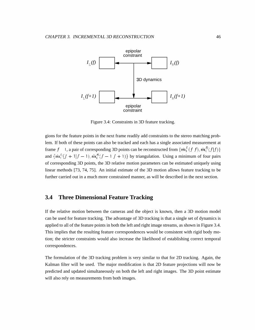
CHAPTER3. INCREMENTAL 3D RECONSTRUCTION 46
epipolarconstraint
epipolarconstraint
3D dynamicsÛ
I (f+1)L I (f+1)R
I (f)L I (f)R
Figure3.4: Constraintsin 3D featuretracking.
gionsfor thefeaturepointsin thenext framereadilyaddconstraintsto thestereomatchingprob-
lem. If bothof thesepointscanalsobetrackedandeachhasa singleassociatedmeasurementat
frame � 8 � , apairof corresponding3D pointscanbereconstructedfrom X¶}< aY Z� Ë ���Z��}< bY Z� Ë ���Z[and XÜ}< aY Z� 8 �¿Ë � 8 � �Z�;}< bY Z� 8 �¿Ë � 8 � �Z[ by triangulation. Using a minimum of four pairs
of corresponding3D points,the3D relative motionparameterscanbeestimateduniquelyusing
linear methods[73, 74, 75]. An initial estimateof the3D motion allows featuretrackingto be
furthercarriedout in amuchmoreconstrainedmanner, aswill bedescribedin thenext section.
3.4 Thr eeDimensionalFeatureTracking
If the relative motion betweenthe camerasand the object is known, thena 3D motion model
canbeusedfor featuretracking.Theadvantageof 3D trackingis thatasinglesetof dynamicsis
appliedto all of thefeaturepointsin boththeleft andright imagestreams,asshown in Figure3.4.
This impliesthat theresultingfeaturecorrespondenceswould beconsistentwith rigid bodymo-
tion; the stricterconstraintswould alsoincreasethe likelihoodof establishingcorrecttemporal
correspondences.
The formulationof the3D trackingproblemis very similar to that for 2D tracking. Again, the
Kalmanfilter will be used. The major modificationis that 2D featureprojectionswill now be
predictedandupdatedsimultaneouslyon both the left andright images.The3D point estimate
will alsorely on measurementsfrom bothimages.
CHAPTER3. INCREMENTAL 3D RECONSTRUCTION 47
3.4.1 Motion and MeasurementModels
In thecaseof 3D featuretracking,thestateto beestimatedis thepositionof 3D featurepoints.
Becausewe areprocessinga stereoimagesequence,stereocorrespondencesbetweenleft and
right imageframescanbeusedto reconstruct3D points.
Thelocationof a3D point is governedby themotionmodel
+ Y Z� 8 � � � d¡Z���o+ Y Z��� 8 �Z���Z: (3.4)
Themeasurementvectornow consistsof thecoordinatesof theextractedfeaturesonboththeleft
andright images,that is,
Ê aY Z���Ê bY Z���
� < aY Z���< bY Z���
8 ¥ a Z���¥ b Z���� ^ - c¸�Z+�Y�Z����0
^ - d¡�Z+ Y Z����08 ¥ a Z���¥ b Z��� �
(3.5)
where is thevectorvaluedprojectionfunctionasin (2.3),and ¥ a Z��� and ¥ b Z��� areGaussian
randomvectorsrepresentingmeasurementnoisein theleft andright imagefeaturesrespectively.
Sincethe samefeatureextractor is used,the measurementnoisewould have the samestatisti-
cal distribution for both images.Using covariance�
asdefinedpreviously in Section3.3, the
covarianceof thenoisevectorin the3D caseis definedby aÍ & Í matrix
�`Ýwhere
�'ݡ� � N v޲N v޲ �
Forsimplification,thewholeimagecoordinatevectorwill bedenotedas< Y Z��� , themeasurement
vectorasÊ Y Z��� , andtheprojectionfunctionas ^ - + Y Z����0 hereafter.
In orderto tracka 3D featurepoint from onestereopair to thenext, thegoal is to find thebest
estimateof its state,i.e., its 3D location,basedon theabove motionandmeasurementmodels.
CHAPTER3. INCREMENTAL 3D RECONSTRUCTION 48
3.4.2 Prediction and Update
Thepredictedlocationof the3D pointandthepredictionuncertaintyin thenext frameare
}+ Y Z� 8 �¿Ë ��� � d }+ Y Z� Ë ��� 8 ��I Y Z� 8 �¿Ë ��� � d I Y Z� Ë ���Zd 1 : (3.6)
Thepredictedmeasurementis
}Ê Y Z� 8 �¿Ë ��� � ^ - }+ Y Z� 8 �¿Ë ����0�:
Sincethemeasurementmodelin this caseis non-linear, an extendedKalmanfilter [55] is used
to maintainlinearity of theestimationtechnique.Thenon-linearfunction ^ hasto be linearised
abouttheestimatedtrajectory. Let ß Z� 8 � � betheJacobianmatrix representingthefirst order
approximationof ^ aboutthepoint }+ Y Z� 8 �¿Ë ��� , that is,
ß�Z� 8 � � � © ^`o+S�© + à=áQâà"ãåä J#æ zZç J#è:
Thenthemeasurementpredictionerrorcovarianceis approximatedas
Ð Y Z� 8 � � � ß�Z� 8 � � I Z� 8 �¿Ë ���Zß 1 Z� 8 � � 8 �`Ý : (3.7)
In 3D tracking,anextractedfeaturepoint from eachof theleft andright imageshasto beassoci-
atedwith theprediction.TheMahalanobisdistancefor eachimageis
¢ a Ñ Zé¨��Ó²� ��- Ê a³ Z� 8 � � { }Ê aê Z� 8 �¿Ë ����0 1 Ð a²aYëZ� 8 � � - Ê a³ Z� 8 � � { }Ê aê Z� 8 �¿Ë ����0��¢ b Ñ �Ò���ì¾� ��- Ê bí Z� 8 � � { }Ê bY Z� 8 �¿Ë ����0 1 Ð b¨bY Z� 8 � � - Ê aí Z� 8 � � { }Ê aY Z� 8 �¿Ë ����0��
where Ð a²aY Z� 8 � � and Ð b!bY Z� 8 � � are V�&�V sub-matricesof Ð Y Z� 8 � � , suchthat
Р�Рa=a ... Рa=b:�:v:_:�:v:_:�:v:_:�:v:_:Рb!a ... Рb!b
CHAPTER3. INCREMENTAL 3D RECONSTRUCTION 49
The sameÖ testasthat in (3.3) is appliedfor associatingnew featurepointswith predictions.
Assumingthat thepoints Ê a³ Z� 8 � � and Ê bí Z� 8 � � have passedthestatisticaltestin (3.3). The
new measurementvectorconsistingof thesetwo pointswill bedenotedÊ ³ í Z� 8 � � , where
Ê ³ í Z� 8 � � � Ê a³ Z� 8 � �Ê bí Z� 8 � � :
Thelocationanderrorcovarianceof the3D point areupdatedasfollows:
}+ Y Z� 8 �¿Ë � 8 � � � }+ Y Z� 8 �¿Ë ��� 89Ø Y Z� 8 � �ZX�Ê ³ í Z� 8 � � { ^ - }+ Y Z� 8 �¿Ë ����0�[x�I Y Z� 8 �¿Ë � 8 � � � I Y Z� 8 �¿Ë ��� { Ø Y Z� 8 � �Zß�Z� 8 � � I Y Z� 8 �¿Ë ���Z�wheretheKalmanfilter gainis
Ø Y Z� 8 � � � I Y Z� 8 �¿Ë ���Zß Z� 8 � �ZÐ y�zY Z� 8 � �Z:
3.4.3 Model Priors
Assumingthat3D trackingcommencesat frame �>P , thentheinitial estimateof a featurepoint’s
3D locationis givenby thereconstructionfrom apairof 2D featurepointsontheleft andright im-
ages.Givenapairof stereomatchingcandidates,X�Ê a³ Z� P �Z�ZÊ bí Z� P �Z[ , }+ ³ í Z� P Ë � P � refersto the3D
point reconstructedfrom the estimatesof the features’true 2D locations, X }< a³ÆZ�>PO�Z� }< bí Z�>PO�Z[ ,usingtheprocessof triangulationasdescribedin Chapter2.
The initial uncertaintyin the estimate,I ³ í Z�>P Ë �>PO� , can be set arbitrarily large. The problem
with this approachis that a large uncertaintywould result in large searchregionsfor predicted
measurementsin thenext frame,whichmayleadto temporalmatchingambiguitiesbecausemany
featurepointsmayfall into thesearchregion. Theapproachpresentedin [65], basedonanalysing
theerrorin triangulation,is usedhereto approximateI ³ í Z�>P Ë �>PO� . [76] hasamorecomprehensive
discussionof thesubject.
Let î beavector-valuedfunctionrepresentingthereconstructionfunction,suchthat
}+ ³ í Z� P Ë � P � � îïoÊ ³ í Z� P �Z�Z:
CHAPTER3. INCREMENTAL 3D RECONSTRUCTION 50
Theerror in }+�³ í Z� P Ë � P � is attributedto theerror in themeasurementvector Ê ³ í Z� P � . According
to themeasurementmodelin (3.5),themeasurementvectorhasaGaussiandistribution with zero
meanandcovarianceof�`Ý
.
To lineariseî , we definetheJacobianmatrix
� �ð© î© Ê ñ á âñ�ò�ó ä J#æ zZç J#è:
ThenI ³ í Z� P Ë � P � canbeapproximatedas
I ³ í Z� P Ë � P � � � � Ý � 1 :
This approximationrepresentsthe uncertaintyin the 3D point estimateas having a Gaussian
distribution with zero-meanandanellipsoidalconstantprobabilitycontour.
3.5 Multiple HypothesisTracking and StereoMatching
In theprevioussections,two alternative trackingschemesfor stereoimagesequenceshave been
presented.They both involve the predictionof featurelocationsin the next imageframes,and
then looking for featurepoints that are locatedwithin the searchregions. However, we have
not discussedthe casewhenmultiple featurepointsarefound within the searchregionson the
images.Moreover, theproblemof robuststereomatchinghasyet to beaddressed.
In 3D reconstruction,we areoften interestedin extractinga large numberof salientfeaturesin
animagein orderto build a denserepresentationof theobject,andeachof thesefeatureshasto
be tracked throughoutthe imagesequence.Wheneachimageis clutteredby a large numberof
features,theproblemof establishingaccuratetemporalcorrespondencesbecomemoredifficult,
becauseit is quitecommonto find morethanonefeatureinsidethesearchregion.
Therearemany statisticaldataassociationtechniquesthataddressthisproblemin multiple target
tracking [60, 62]. In particular, onemethodis to usemultiple hypothesistracking [64]. The
advantageof this technique,asshown in Figure3.5,is thatmatchingambiguitiesarenot resolved
immediately, but insteada decisionis deferreduntil moreinformationis available. Thegeneral
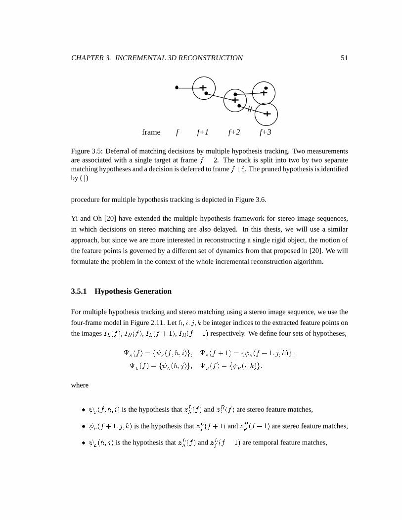
CHAPTER3. INCREMENTAL 3D RECONSTRUCTION 51
frame f f+1 f+2 f+3
Figure3.5: Deferralof matchingdecisionsby multiple hypothesistracking.Two measurementsareassociatedwith a single target at frame � 8 V . The track is split into two by two separatematchinghypothesesandadecisionis deferredto frame � 8 % . Theprunedhypothesisis identifiedby ( ô )procedurefor multiple hypothesistrackingis depictedin Figure3.6.
Yi andOh [20] have extendedthe multiple hypothesisframework for stereoimagesequences,
in which decisionson stereomatchingare also delayed. In this thesis,we will usea similar
approach,but sincewe aremoreinterestedin reconstructinga singlerigid object,themotionof
thefeaturepointsis governedby a differentsetof dynamicsfrom thatproposedin [20]. We will
formulatetheproblemin thecontext of thewholeincrementalreconstructionalgorithm.
3.5.1 HypothesisGeneration
For multiple hypothesistrackingandstereomatchingusinga stereoimagesequence,we usethe
four-framemodelin Figure2.11.Let é¿��ÒO��Ó$��ì beintegerindicesto theextractedfeaturepointson
theimages�Za Z��� , �Zb Z��� , �Za Z� 8 � � , �Zb Z� 8 � � respectively. Wedefinefour setsof hypotheses,
õ;ö Z��� � XO÷ ö Z�¾��é¨��Ò��Z[x� õ;ö Z� 8 � � � XO÷ ö Z� 8 � ��Ó$��ì¾�Z[x�õ t�Z��� � XO÷'t¾Zé¿��Ó6�Z[x� õ w¨Z��� � XO÷`w��ÒO��ì¾�Z[x�where
� ÷ ö Z�¾��é¿��ÒO� is thehypothesisthat Ê aê Z��� and Ê bY Z��� arestereofeaturematches,
� ÷ ö Z� 8 � ��Ó$��ì¾� is thehypothesisthat Ê a³ Z� 8 � � andÊ bí Z� 8 � � arestereofeaturematches,
� ÷'t¾Zé¨��Ó²� is thehypothesisthat Ê aê Z��� and Ê a³ Z� 8 � � aretemporalfeaturematches,
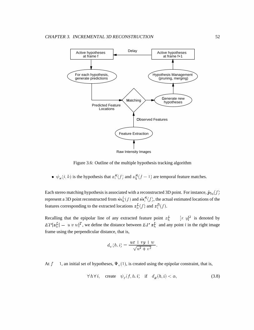
CHAPTER3. INCREMENTAL 3D RECONSTRUCTION 52
Raw Intensity Images
Observed Featuresø
Predicted Feature Locations
Delay
Matchingù
Hypothesis Management (pruning, merging)
For each hypothesis,generate predictions
Feature Extraction
Active hypotheses at frame f
Active hypotheses at frame f+1
Generate newú hypotheses
Figure3.6: Outlineof themultiple hypothesistrackingalgorithm
� ÷ w �Ò���ì¾� is thehypothesisthat Ê bY Z��� and Ê bí Z� 8 � � aretemporalfeaturematches.
Eachstereomatchinghypothesisisassociatedwith areconstructed3D point. For instance,}+ ê Y�Z���representa3D point reconstructedfrom }< aê Z��� and }< bY Z��� , theactualestimatedlocationsof the
featurescorrespondingto theextractedlocationsÊ aê Z��� and Ê bY Z��� .Recalling that the epipolar line of any extractedfeaturepoint Ê aê � - �9�²0 1 is denotedby
� I - Ê aê 0 �û-�� R 0 1 , we definethedistancebetween� I - Ê aê 0 andany point Ò in theright image
frameusingtheperpendiculardistance,thatis,
¢=ü�Zé¨��Ò�� � Ë� �
8 � � 8 R Ëý� 8 � :
At � ��� , aninitial setof hypotheses,õ ö � � , is createdusingtheepipolarconstraint,thatis,
þ é þ Ò�� create ÷ ö Z�¾��é¿��Ò�� if ¢²ü�Zé¿��Ò���Ô�ÿ�� (3.8)
CHAPTER3. INCREMENTAL 3D RECONSTRUCTION 53
whereÿ is setto asmallvalueto accountfor errorsin featureextractionandquantizationeffects.
The value for ÿ canbe determinedas a function of the noisemodel for the 2D featurepoint
measurements.
Now consideraparticularstereomatchinghypothesis÷ ö Z�¾��é¨PL��ÒOPL� betweenthepoints é!P andÒLP .Eithertwo-dimensionalor three-dimensionaltrackingasdescribedin Section3.3andSection3.4
canbe usedto make the predictions }Ê aê�� Z� 8 �¿Ë ��� and }Ê bY � Z� 8 �¿Ë ��� . Insteadof associatinga
singlefeaturepoint to eachprediction,temporalmatchinghypothesesaregenerated.
Usingthedefinitionof Mahalanobisdistancein (3.2), temporalmatchinghypothesesarecreated
asfollow:
þ Ó"� create ÷ t Zé P ��Ó²� if ¢=Ñ�Zé P ��Ó6�¸ÔÎÕQ�þ ì¾� create ÷'w��Ò P ��ì¾� if ¢ Ñ �Ò P ��ì¾�ïÔÎÕQ:
Then,new stereomatchinghypothesescanbecreated:
þ Ó þ ì¾� create ÷ ö Z� 8 � ��Ó$��ì¾� if
� ÷'t¾Zé P ��Ó²� and� ÷'w��ÒOPL��ì¾� and
¢=ü��Ó"��ì¾�¸Ô�ÿ�:(3.9)
By the combinationof the conditions in (3.8) and (3.9), each stereomatching hypothesis
÷ ö Z� 8 � ��Ó$��ì¾� satisfiesfour setsof constraints:two frame-to-framemotionconstraintsandtwo
view-to-view epipolarconstraints.For instance,if a point é¨P hasseveralstereomatchingcandi-
dates,theapplicationof thethreeadditionalconstraintsin (3.9)would helpto rejectsomeof the
falsestereohypothesesfrom thepreviousframe.
3.5.2 HypothesisManagement
Thehypothesisgenerationstepjust describedabove doesnot applyany globalconstraintswhen
new stereomatchinghypothesesarecreated.Sincefor eachstereohypothesis÷ ö Z�¾��é¿��Ò�� several
temporalmatchinghypothesesmay be generated,it is often possiblethat morethanonestereo
hypothesisis createdwith the samematchingfeaturepoints at frame � 8 �. An exampleis
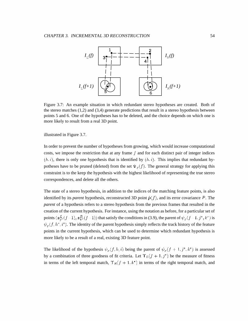
CHAPTER3. INCREMENTAL 3D RECONSTRUCTION 54
1 2�
3�
4�
I (f+1)L I (f+1)R
I (f)L I (f)R
5�
6
Figure 3.7: An examplesituationin which redundantstereohypothesesare created. Both ofthestereomatches(1,2)and(3,4)generatepredictionsthatresultin a stereohypothesisbetweenpoints5 and6. Oneof thehypotheseshasto bedeleted,andthechoicedependson which oneismorelikely to resultfrom areal3D point.
illustratedin Figure3.7.
In orderto preventthenumberof hypothesesfrom growing, whichwould increasecomputational
costs,we imposetherestrictionthatat any frame � andfor eachdistinctpair of integer indices
Zé¿��ÒO� , thereis only onehypothesisthat is identifiedby Zé¿��Ò�� . This implies that redundanthy-
potheseshave to bepruned(deleted)from thesetõ ö Z��� . Thegeneralstrategy for applyingthis
constraintis to thekeepthehypothesiswith thehighestlikelihoodof representingthetruestereo
correspondences,anddeleteall theothers.
Thestateof a stereohypothesis,in additionto theindicesof thematchingfeaturepoints,is also
identifiedby its parenthypothesis,reconstructed3D point }+QZ��� , andits errorcovarianceI
. The
parentof a hypothesisrefersto a stereohypothesisfrom thepreviousframesthatresultedin the
creationof thecurrenthypothesis.For instance,usingthenotationasbefore,for aparticularsetof
points oÊ a³ � Z� 8 � �Z�ZÊ bí�� Z� 8 � �Z� thatsatisfytheconditionsin (3.9),theparentof ÷ ö Z� 8 � ��Ó P ��ì P � is
÷ ö Z�¾��é P ��Ò P � . Theidentityof theparenthypothesissimplyreflectsthetrackhistoryof thefeature
pointsin thecurrenthypothesis,which canbeusedto determinewhich redundanthypothesisis
morelikely to bea resultof a real,existing3D featurepoint.
The likelihood of the hypothesis÷ ö Z�¾��é¨��Ò�� being the parentof ÷ ö Z� 8 � ��Ó6P���ì�PL� is assessed
by a combinationof threegoodnessof fit criteria. Let � a Z� 8 � ��Ó P � be themeasureof fitness
in termsof the left temporalmatch, � b Z� 8 � ��ì�P�� in termsof the right temporalmatch,and
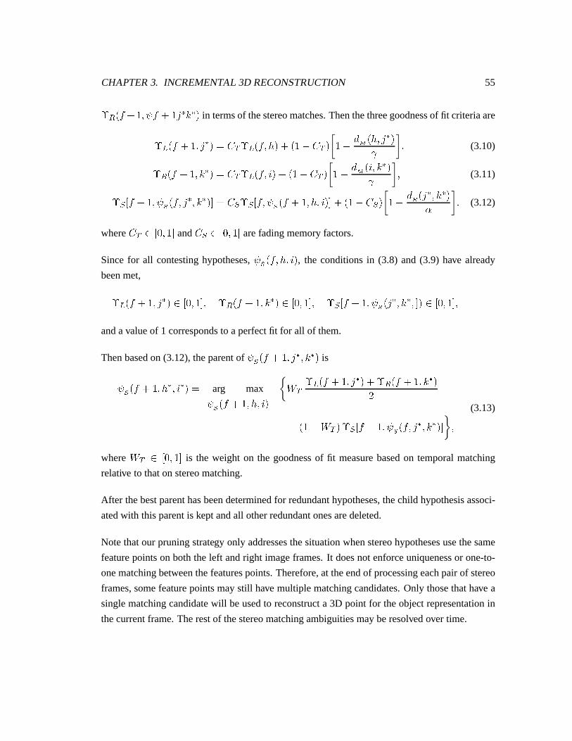
CHAPTER3. INCREMENTAL 3D RECONSTRUCTION 55
� b Z� 8 � ��÷)� 8 � Ó P ì P � in termsof thestereomatches.Thenthethreegoodnessof fit criteriaare
� a Z� 8 � ��Ó P � � 1 � a Z�¾��é¨�8 �`{� 1 � �`{ ¢ Ñ Zé¿��Ó¾P_�Õ � (3.10)
� b Z� 8 � ��ì P � � 1 � a Z�¾��Ò��8 �`{� 1 � �`{ ¢ Ñ �Ò���ì�P��Õ � (3.11)
�`Á - � 8 � ��÷ ö Z�¾��Ó P ��ì P ��0 � Á��`Á - �¾��÷ ö Z� 8 � ��é¿��Ò���0 8 �`{� ÁÆ� �`{ ¢=ü��Ó P ��ì P �ÿ : (3.12)
where 1 - N � � 0 and
Á - N � � 0 arefadingmemoryfactors.
Sincefor all contestinghypotheses,÷ ö Z�¾��é¿��Ò�� , the conditionsin (3.8) and(3.9) have already
beenmet,
� a Z� 8 � ��Ó P � - N � � 0�� � b Z� 8 � ��ì P � - N � � 0�� � Á - � 8 � ��÷ ö �Ó P ��ì P ��0�� - N � � 0��andavalueof 1 correspondsto aperfectfit for all of them.
Thenbasedon (3.12),theparentof ÷ ö Z� 8 � ��Ó6P���ì�PL� is
÷ ö Z� 8 � ��é P ��Ò P � � arg max
÷ ö Z� 8 � ��é¨��Ò��� 1 �
a Z� 8 � ��Ó¾P�� 8 � b Z� 8 � ��ì�PL�V8 �`{ � 1 ���`Á - �
8 � ��÷ ö Z�¾��Ó P ��ì P ��0 �(3.13)
where� 1 - N � � 0 is the weight on the goodnessof fit measurebasedon temporalmatching
relative to thaton stereomatching.
After thebestparenthasbeendeterminedfor redundanthypotheses,thechild hypothesisassoci-
atedwith thisparentis keptandall otherredundantonesaredeleted.
Notethatour pruningstrategy only addressesthesituationwhenstereohypothesesusethesame
featurepointson boththeleft andright imageframes.It doesnot enforceuniquenessor one-to-
onematchingbetweenthefeaturespoints.Therefore,at theendof processingeachpairof stereo
frames,somefeaturepointsmaystill have multiple matchingcandidates.Only thosethathave a
singlematchingcandidatewill beusedto reconstructa 3D point for theobjectrepresentationin
thecurrentframe.Therestof thestereomatchingambiguitiesmayberesolvedover time.

CHAPTER3. INCREMENTAL 3D RECONSTRUCTION 56
Preliminaryresultsof the multiple hypothesistracking and stereomatchingalgorithmwill be
presentedin thenext chapter.
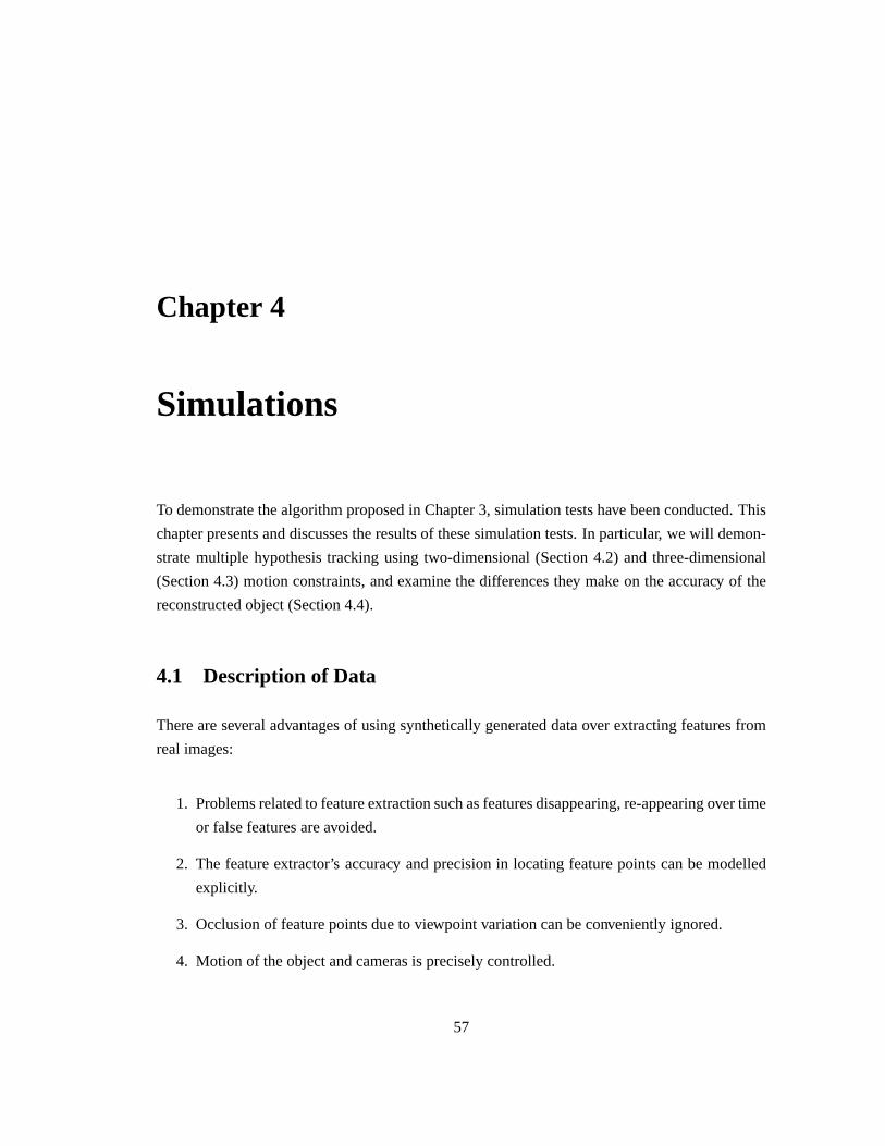
Chapter 4
Simulations
To demonstratethealgorithmproposedin Chapter3, simulationtestshave beenconducted.This
chapterpresentsanddiscussestheresultsof thesesimulationtests.In particular, we will demon-
stratemultiple hypothesistrackingusingtwo-dimensional(Section4.2) and three-dimensional
(Section4.3) motionconstraints,andexaminethedifferencesthey make on theaccuracy of the
reconstructedobject(Section4.4).
4.1 Description of Data
Thereareseveraladvantagesof usingsyntheticallygenerateddataover extractingfeaturesfrom
realimages:
1. Problemsrelatedto featureextractionsuchasfeaturesdisappearing,re-appearingovertime
or falsefeaturesareavoided.
2. The featureextractor’s accuracy andprecisionin locatingfeaturepointscanbe modelled
explicitly.
3. Occlusionof featurepointsdueto viewpoint variationcanbeconvenientlyignored.
4. Motion of theobjectandcamerasis preciselycontrolled.
57
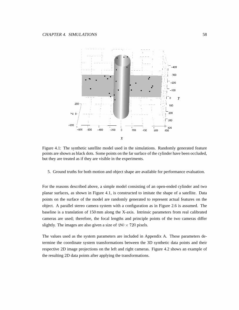
CHAPTER4. SIMULATIONS 58
Figure4.1: The syntheticsatellitemodelusedin the simulations.Randomlygeneratedfeaturepointsareshown asblackdots.Somepointsonthefarsurfaceof thecylinderhavebeenoccluded,but they aretreatedasif they arevisible in theexperiments.
5. Groundtruthsfor bothmotionandobjectshapeareavailablefor performanceevaluation.
For the reasonsdescribedabove, a simplemodelconsistingof an open-endedcylinder andtwo
planarsurfaces,asshown in Figure4.1, is constructedto imitate the shapeof a satellite. Data
pointson the surfaceof the modelare randomlygeneratedto representactualfeatureson the
object. A parallelstereocamerasystemwith a configurationasin Figure2.6 is assumed.The
baselineis a translationof 150mm alongthe X-axis. Intrinsic parametersfrom real calibrated
camerasare used; therefore,the focal lengthsand principle points of the two camerasdiffer
slightly. Theimagesarealsogivenasizeof�� N &��xV N pixels.
The valuesusedas the systemparametersare includedin AppendixA. Theseparametersde-
terminethe coordinatesystemtransformationsbetweenthe 3D syntheticdatapointsand their
respective 2D imageprojectionson the left andright cameras.Figure4.2 shows anexampleof
theresulting2D datapointsafterapplyingthetransformations.
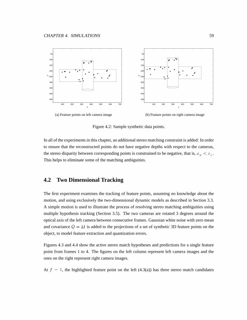
CHAPTER4. SIMULATIONS 59
100 200 300 400 500 600 700
50
100
150
200
250
300
350
400
450
x
y
(a)Featurepointson left cameraimage
100 200 300 400 500 600 700
50
100
150
200
250
300
350
400
450
x
y
(b) Featurepointson right cameraimage
Figure4.2: Samplesyntheticdatapoints.
In all of theexperimentsin thischapter, anadditionalstereomatchingconstraintisadded:In order
to ensurethat the reconstructedpointsdo not have negative depthswith respectto thecameras,
thestereodisparitybetweencorrespondingpointsis constrainedto benegative, thatis, ��������� .Thishelpsto eliminatesomeof thematchingambiguities.
4.2 Two DimensionalTracking
Thefirst experimentexaminesthe trackingof featurepoints,assumingno knowledgeaboutthe
motion,andusingexclusively thetwo-dimensionaldynamicmodelsasdescribedin Section3.3.
A simplemotionis usedto illustratetheprocessof resolvingstereomatchingambiguitiesusing
multiple hypothesistracking(Section3.5). The two camerasare rotated3 degreesaroundthe
opticalaxisof theleft camerabetweenconsecutive frames.Gaussianwhitenoisewith zeromean
andcovariance��� �"! is addedto theprojectionsof a setof synthetic3D featurepointson the
object,to modelfeatureextractionandquantizationerrors.
Figures4.3and4.4show theactive stereomatchhypothesesandpredictionsfor a singlefeature
point from frames1 to 4. The figureson the left columnrepresentleft cameraimagesandthe
oneson theright representright cameraimages.
At #�%$ , the highlightedfeaturepoint on the left (4.3(a))hasthreestereomatchcandidates
CHAPTER4. SIMULATIONS 60
on theright image(4.3(b))thatsatisfythebasicepipolarconstraints,two of which areincorrect
matches.The locationsof thesefour pointsat #&�'� arepredictedusinga first orderestimator
(4.3(c),4.3(d)).Sinceat #(�)� , the featurepoint associatedwith Hypothesis1 no longersatis-
fies theepipolarconstraint,it is rejectedandthe numberof active hypothesesdecreasesto two
(4.3(e),4.3(f)). The locationsof the remaininghypothesesat #*�,+ arenow predictedusinga
secondorderestimator(4.4(a),4.4(b)).Similarly, thefeaturepointsassociatedwith Hypothesis2
do not satisfytheepipolarconstraint,andthereforearerejected.Theonly remainingactive hy-
pothesisis thecorrectstereomatchfor thepoint (4.4(c),4.4(d)).Thelocationsof this hypothesis
predictedusinga secondorderestimatorat #-�/. areshown in 4.4(e)and4.4(f). Notice that
theuncertainlyregionsof thesepredictionsareslightly larger thanthosein theprevious frames.
This is becausethemeasurementnoisehasa largercontribution to themeasurementuncertainty
in thesecondorderestimatorthanthezeroandfirst orderestimators.Thesizeof theseregions
will remainvery muchconstantfor futureframes.
4.3 Thr eeDimensionalTracking
Thesecondexperimentexaminesthethree-dimensionaltrackingof thefeaturepointsasdescribed
in Section3.4 aswell astheprocessof resolvingstereomatchingambiguities.All theassump-
tionsaboutthestereocamerasystem,motion,andmeasurementnoisearethesameasthosefor
the2D trackingexample. For this experimentonly, we will assumethat themotionparameters
areknown a priori for demonstrationpurposes,suchthat an exact 3D dynamicsmodelis used
for thepredictionandestimationof featurepoint locations.Of course,our eventualgoal is not
to assumeknown motion, but to estimatethe motion parameters.However, we will leave this
discussionuntil Chapter5.
Figures4.5and4.6show theactive stereomatchhypothesesandpredictionsfor a singlefeature
point from frames1 to 4. In this case,each3D point hypothesisgeneratesa slightly different
predictionin the left frame. As a result,all the differentpredictionsfor all the hypothesesare
shown in left framesof Figures4.5 and4.6. A different featurepoint from the onein the 2D
trackingexamplewaschosenfor demonstrationpurposes.At #0�$ , thereis atotalof four stereo
matchinghypothesesfor the selectedfeaturepoint including the correctmatch(4.5(a),4.5(b)).
Similar to the2D trackingexample,the incorrectmatchesarerejectedover time andby #1�2. ,only two hypothesesremainactive (4.6(c),4.6(d)).It caneasilybeseenthat theremainingfalse
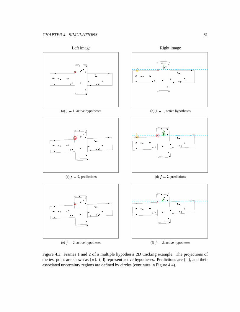
CHAPTER4. SIMULATIONS 61
Left image Right image
(a) 35476 , active hypotheses
12
(b) 38476 , active hypotheses
(c) 354:9 , predictions
12
(d) 35479 , predictions
(e) 35479 , active hypotheses
2
(f) 354:9 , active hypotheses
Figure4.3: Frames1 and2 of a multiple hypothesis2D trackingexample. The projectionsofthe testpoint areshown as( ; ). ( < ) representactive hypotheses.Predictionsare( = ), andtheirassociateduncertaintyregionsaredefinedby circles(continuesin Figure4.4).
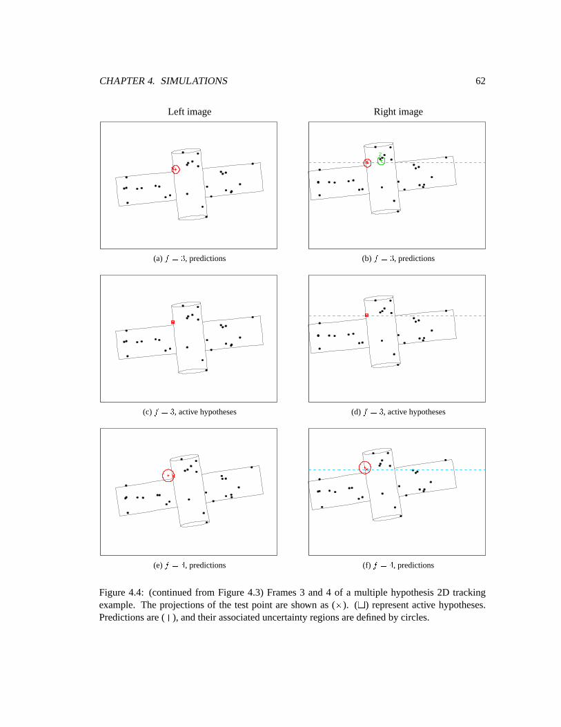
CHAPTER4. SIMULATIONS 62
Left image Right image
(a) 354:> , predictions
2
(b) 3547> , predictions
(c) 3547> , active hypotheses (d) 3847> , active hypotheses
(e) 354@? , predictions (f) 354A? , predictions
Figure4.4: (continuedfrom Figure4.3) Frames3 and4 of a multiple hypothesis2D trackingexample. The projectionsof the testpoint areshown as( ; ). (< ) representactive hypotheses.Predictionsare( = ), andtheir associateduncertaintyregionsaredefinedby circles.
CHAPTER4. SIMULATIONS 63
match,Hypothesis3, will be rejectedat the next framebecausethereis no other featurepoint
within thesearchregionof thathypothesis(4.6(e),4.6(f)).
4.4 Incr ementalReconstruction
In the two previous trackingexperiments,ambiguitiesin stereomatchingareresolved within a
few numberof frames. It is importantto point out that, of course,not all featurepoints will
alwaysbematchedcorrectlyusingthismethod,while othersmayhavenoambiguitiesatall from
thefirst pair of frames.
Thelasttwo experimentssimply illustratehow multiplehypothesistrackingworksunder2D and
3D tracking.Wenow demonstratetheaccuracy of theactualstructureestimatesin thesametwo
separatescenarios:usingeither2D trackingor 3D trackingexclusively. In eachof thefollowing
cases,the motion is the sameas the previous two demonstrations.Furthermore,only feature
pointson the left imagewith just oneactive stereomatchhypothesisfrom the right imageare
reconstructedat eachframe. All points are expressedin termsof the left cameracoordinate
systemat frame1.
In thefirst experiment,solely2D trackingis usedthroughoutthe imagesequenceandno noise
wasaddedto thegenerated2D measurements.Figure4.7 illustratestheresultsof reconstructing
3D pointsfrom validatedstereocorrespondencesat frames1, 10,and20. Thefigureson theleft
columnshow the reconstructedB and C valuesof the points,and the right columnshow the
reconstructeddepthvaluesD on theverticalaxis,bothalongwith groundtruth.
As shown in Figure4.7,thereconstructed3D pointsaregenerallyquiteaccuratewhenthereis no
measurementnoise.At frame1, unambiguousstereomatchescanreadilybefoundfor anumber
of featurepoints.Thereasonis clearby observingthattheseparticularpointswouldhave unique
correspondencesbetweenthe left andright imagesasno otherfeaturepointswould satisfythe
epipolarconstraint. As more imageframesare available, the numberof points reconstructed
increases.
Figure 4.8 summarizesthe resultsof this experiment. The total numberof active hypotheses
at eachframedecreasessignificantlywhile the numberof reconstructedpointsincreasesin the
first five frames.Althoughtherewasonemismatchedpoint at someof theframes,thestructure
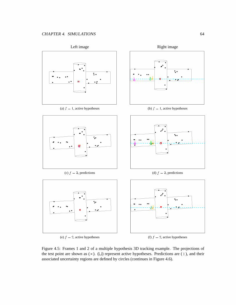
CHAPTER4. SIMULATIONS 64
Left image Right image
(a) 35476 , active hypotheses
123
(b) 38476 , active hypotheses
(c) 354:9 , predictions
1 23
(d) 35479 , predictions
(e) 35479 , active hypotheses
23
(f) 354:9 , active hypotheses
Figure4.5: Frames1 and2 of a multiple hypothesis3D trackingexample. The projectionsofthe testpoint areshown as( ; ). ( < ) representactive hypotheses.Predictionsare( = ), andtheirassociateduncertaintyregionsaredefinedby circles(continuesin Figure4.6).
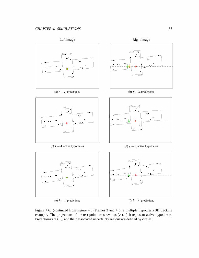
CHAPTER4. SIMULATIONS 65
Left image Right image
(a) 354:> , predictions
23
(b) 3547> , predictions
(c) 3547> , active hypotheses
3
(d) 3847> , active hypotheses
(e) 354@? , predictions
3
(f) 354A? , predictions
Figure4.6: (continuedfrom Figure4.5) Frames3 and4 of a multiple hypothesis3D trackingexample. The projectionsof the testpoint areshown as( ; ). (< ) representactive hypotheses.Predictionsare( = ), andtheir associateduncertaintyregionsaredefinedby circles.
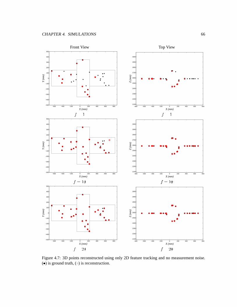
CHAPTER4. SIMULATIONS 66
FrontView TopView
−600 −400 −200 0 200 400 600 800−500
−400
−300
−200
−100
0
100
200
300
400
500
X (mm)
Y (
mm
)
−800 −600 −400 −200 0 200 400 600 8002100
2200
2300
2400
2500
2600
2700
2800
2900
3000
X (mm)
Z (
mm
)
#E�F$ #E�F$
−600 −400 −200 0 200 400 600 800−500
−400
−300
−200
−100
0
100
200
300
400
500
X (mm)
Y (
mm
)
−800 −600 −400 −200 0 200 400 600 8002100
2200
2300
2400
2500
2600
2700
2800
2900
3000
X (mm)
Z (
mm
)
#E�$"G #��F$"G
−600 −400 −200 0 200 400 600 800−500
−400
−300
−200
−100
0
100
200
300
400
500
X (mm)
Y (
mm
)
−800 −600 −400 −200 0 200 400 600 8002100
2200
2300
2400
2500
2600
2700
2800
2900
3000
X (mm)
Z (
mm
)
#E��"G #��F�"GFigure4.7: 3D pointsreconstructedusingonly 2D featuretrackingandno measurementnoise.( H ) is groundtruth, ( I ) is reconstruction.
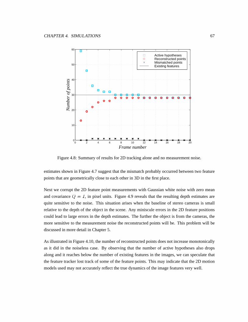
CHAPTER4. SIMULATIONS 67
0 2 4 6 8 10 12 14 16 18 200
10
20
30
40
50
60
Frame number
Nu
mb
er
of p
oin
ts
Active hypothesesReconstructed pointsMismatched pointsExisting features
Figure4.8: Summaryof resultsfor 2D trackingaloneandnomeasurementnoise.
estimatesshown in Figure4.7suggestthatthemismatchprobablyoccurredbetweentwo feature
pointsthataregeometricallycloseto eachotherin 3D in thefirst place.
Next we corruptthe2D featurepoint measurementswith Gaussianwhite noisewith zeromean
andcovariance�,�J! , in pixel units. Figure4.9 revealsthat the resultingdepthestimatesare
quite sensitive to the noise. This situationariseswhenthe baselineof stereocamerasis small
relative to thedepthof theobjectin thescene.Any minisculeerrorsin the2D featurepositions
could leadto largeerrorsin thedepthestimates.Thefurthertheobjectis from thecameras,the
moresensitive to themeasurementnoisethe reconstructedpointswill be. This problemwill be
discussedin moredetail in Chapter5.
As illustratedin Figure4.10,thenumberof reconstructedpointsdoesnot increasemonotonically
as it did in the noiselesscase. By observingthat the numberof active hypothesesalsodrops
alongandit reachesbelow thenumberof existing featuresin the images,we canspeculatethat
thefeaturetracker lost trackof someof thefeaturepoints.This mayindicatethatthe2D motion
modelsusedmaynotaccuratelyreflectthetruedynamicsof theimagefeaturesvery well.
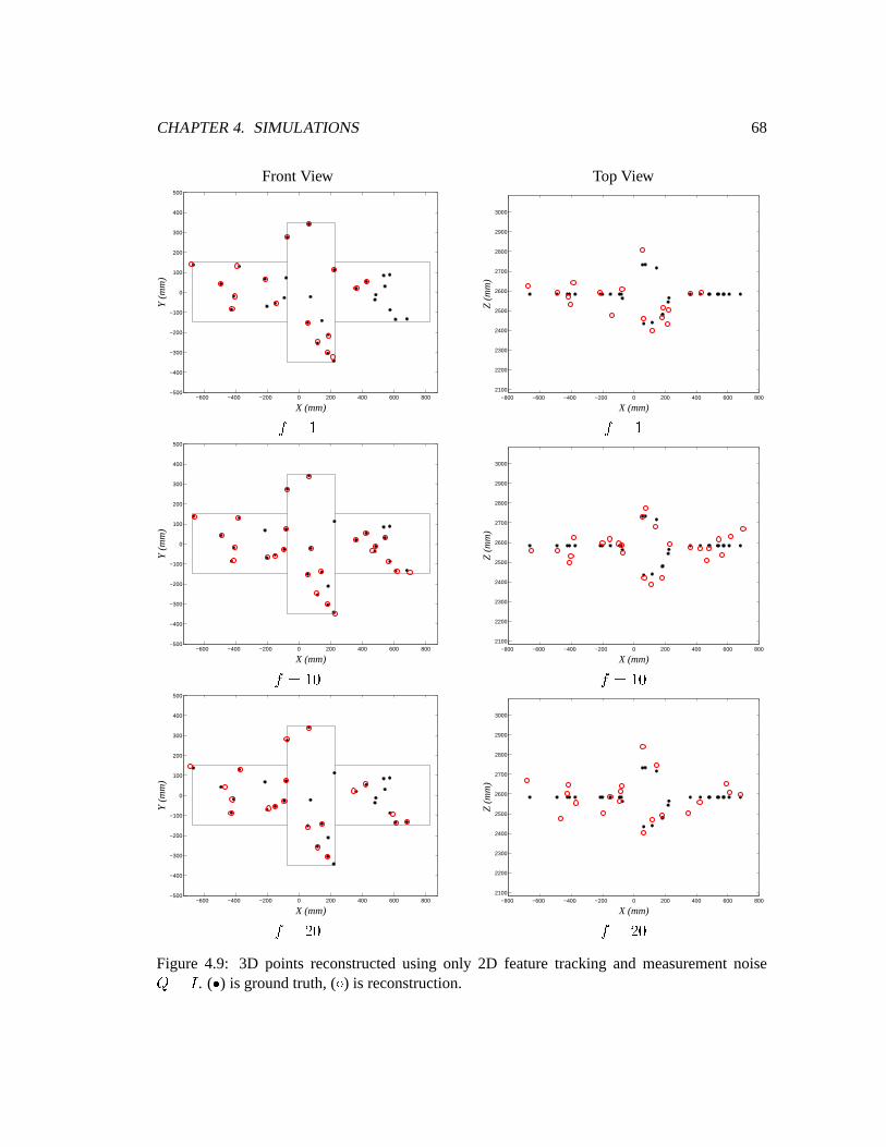
CHAPTER4. SIMULATIONS 68
FrontView TopView
−600 −400 −200 0 200 400 600 800−500
−400
−300
−200
−100
0
100
200
300
400
500
X (mm)
Y (
mm
)
−800 −600 −400 −200 0 200 400 600 8002100
2200
2300
2400
2500
2600
2700
2800
2900
3000
X (mm)
Z (
mm
)
#E�F$ #E�F$
−600 −400 −200 0 200 400 600 800−500
−400
−300
−200
−100
0
100
200
300
400
500
X (mm)
Y (
mm
)
−800 −600 −400 −200 0 200 400 600 8002100
2200
2300
2400
2500
2600
2700
2800
2900
3000
X (mm)
Z (
mm
)
#E�$"G #��F$"G
−600 −400 −200 0 200 400 600 800−500
−400
−300
−200
−100
0
100
200
300
400
500
X (mm)
Y (
mm
)
−800 −600 −400 −200 0 200 400 600 8002100
2200
2300
2400
2500
2600
2700
2800
2900
3000
X (mm)
Z (
mm
)
#E��"G #��F�"GFigure 4.9: 3D points reconstructedusing only 2D featuretracking and measurementnoise��! . ( H ) is groundtruth, ( I ) is reconstruction.
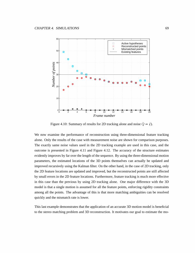
CHAPTER4. SIMULATIONS 69
0 2 4 6 8 10 12 14 16 18 200
10
20
30
40
50
60
Frame number
Nu
mb
er
of p
oin
ts
Active hypothesesReconstructed pointsMismatched pointsExisting features
Figure4.10:Summaryof resultsfor 2D trackingaloneandnoise ��F! ).We now examinethe performanceof reconstructionusing three-dimensionalfeaturetracking
alone.Only theresultsof thecasewith measurementnoiseareshown for comparisonpurposes.
The exactly samenoisevaluesusedin the 2D trackingexampleareusedin this case,and the
outcomeis presentedin Figure4.11 andFigure4.12. The accuracy of the structureestimates
evidently improvesby faroverthelengthof thesequence.By usingthethree-dimensionalmotion
parameters,the estimatedlocationsof the 3D points themselves can actually be updatedand
improvedrecursively usingtheKalmanfilter. On theotherhand,in thecaseof 2D tracking,only
the2D featurelocationsareupdatedandimproved,but thereconstructedpointsarestill affected
by smallerrorsin the2D featurelocations.Furthermore,featuretrackingis muchmoreeffective
in this casethan the previous by using2D tracking alone. Onemajor differencewith the 3D
modelis thata singlemotion is assumedfor all thefeaturepoints,enforcingrigidity constraints
amongall thepoints. The advantageof this is thatmorematchingambiguitiescanberesolved
quickly andthemismatchrateis lower.
This lastexampledemonstratesthattheapplicationof anaccurate3D motionmodelis beneficial
to thestereomatchingproblemand3D reconstruction.It motivatesour goal to estimatethemo-
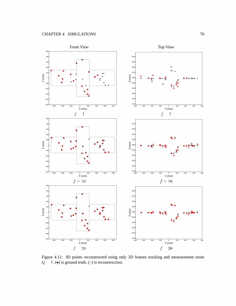
CHAPTER4. SIMULATIONS 70
FrontView TopView
−600 −400 −200 0 200 400 600 800−500
−400
−300
−200
−100
0
100
200
300
400
500
X (mm)
Y (
mm
)
−800 −600 −400 −200 0 200 400 600 8002100
2200
2300
2400
2500
2600
2700
2800
2900
3000
X (mm)
Z (
mm
)
#E�F$ #E�F$
−600 −400 −200 0 200 400 600 800−500
−400
−300
−200
−100
0
100
200
300
400
500
X (mm)
Y (
mm
)
−800 −600 −400 −200 0 200 400 600 8002100
2200
2300
2400
2500
2600
2700
2800
2900
3000
X (mm)
Z (
mm
)
#E�$"G #��F$"G
−600 −400 −200 0 200 400 600 800−500
−400
−300
−200
−100
0
100
200
300
400
500
X (mm)
Y (
mm
)
−800 −600 −400 −200 0 200 400 600 8002100
2200
2300
2400
2500
2600
2700
2800
2900
3000
X (mm)
Z (
mm
)
#E��"G #��F�"GFigure 4.11: 3D points reconstructedusing only 3D featuretracking and measurementnoise��$ . ( H ) is groundtruth, ( I ) is reconstruction.
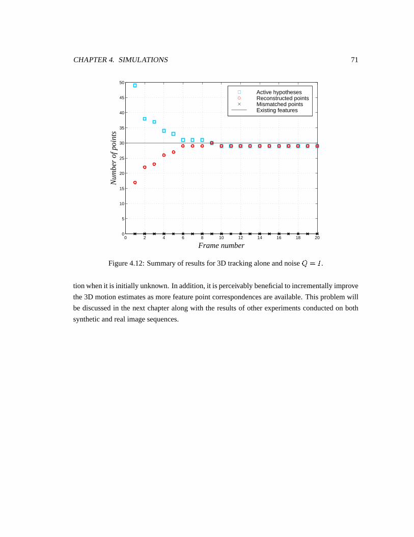
CHAPTER4. SIMULATIONS 71
0 2 4 6 8 10 12 14 16 18 200
5
10
15
20
25
30
35
40
45
50
Frame number
Nu
mb
er
of p
oin
ts
Active hypothesesReconstructed pointsMismatched pointsExisting features
Figure4.12:Summaryof resultsfor 3D trackingaloneandnoise ��F! .tion whenit is initially unknown. In addition,it is perceivablybeneficialto incrementallyimprove
the3D motionestimatesasmorefeaturepoint correspondencesareavailable.This problemwill
be discussedin the next chapteralongwith the resultsof otherexperimentsconductedon both
syntheticandrealimagesequences.
Chapter 5
ExtensionsFor Real ImageProcessing
In theprevious two chapters,thebasicformulationof the incrementalreconstructionalgorithm
hasbeenprovided (Chapter3) and testedon a setof syntheticdatain controlledexperiments
(Chapter4). However, in order to apply the algorithmon real imagesequences,a numberof
extensionshave to be implemented. This chapterwill discussand presentthe resultsof two
additions:motionestimation(Section5.1)andaddingnew features(Section5.3).
5.1 Motion Estimation
It hasbeenshown in Chapter4 thatif the3D motionparametersareknown a priori , thetracking
andreconstructionof 3D featurepointsaremuchmoreaccuratethantrackingtheindividual 2D
projectedpoints. Unfortunately, in most real life applications,suchas the one involving free
floatingobjectsin space,themotionis unknown. Consequently, motionestimationis anecessary
intermediatestepfor obtaininga3D motionmodel.
Oneadvantageof usinga stereoimagesequencefor motion estimationis that the threedimen-
sional locationof pointscanbe first establishedby stereovision techniques.Thenmotion can
beestimatedusing3D insteadof 2D point temporalcorrespondencesbetweenimageframesand
uniquemotionestimatescanbeobtained.
72
CHAPTER5. EXTENSIONSFORREAL IMAGE PROCESSING 73
5.1.1 LeastSquaresEstimation
Motion estimationis often formulatedasa linear leastsquaresestimationproblem. Using the
motionmodeldefinedin (3.4),theobjective functionto minimizebecomes
KMLONQPORTS �UVXWZY[]\ V L #@=*$ S�^`_ NQL # S \ V L # S = RaL # Scb [edgf (5.1)
Given a minimum of threepairsof point correspondencesh \ V L # SOP \ V L #7=`$ SOi , the motion es-
timates jNQL # S and jRkL # S canbe computed.HuangandBlostein [73] presenteda solutionusing
iterative leastsquares.A non-iterative algorithmbasedon singularvaluedecomposition(SVD)
wassuggestedby Arun et.al. [74] to find aclosed-formsolution.Umeyama[75] providedmodi-
ficationsto [74] to ensurethata correctrotationmatrix insteadof a reflectionis computedwhen
thedatais noisy.
Oneproblemwith the basicleastsquaresapproachis that the 3D pointsusedin the objective
function (5.1) containnoiseasa resultof reconstructionfrom noisy 2D measurements.In or-
der to obtainaccuratemotion estimates,theseerrorshave to be accountedfor in the estimator.
ChaudhuriandChatterjee[77] analysedthe performanceof total leastsquares(TLS) methods;
however, they pointedout that the rotationmatrix computedusingstrict TLS is not necessarily
orthonormal.Furthermore,GorynandHein [78] showedthatunderorthonormalconstraints,the
resultsof TLS is equivalentto thoseof theSVD methodproposedin [74]
Wenget. al. [79] presenteda weightedleastsquares(WLS) solutionto theproblem. As shown
in Figure5.1,theamountof uncertaintyof a reconstructed3D point in eachcoordinatedirection
dependsonthepositionof thepointrelative to thecameras.In mostcases,the D coordinateof the
reconstructed3D point is theleasttrustworthy. Hencefor WLS, eachof theL B P C P D S coordinate
of the3D point is weighteddifferently whencomputingtheestimateof themotionparameters.
It wasshown thattheWLS approachachievesmuchmoreaccurateresultsthanunweightedleast
squares.
In this thesis,theWLS methodis usedfor motionestimationbecausewe have seenin Chapter4
how sensitive to noisethedepthestimatescanbe. Thedetailsof thealgorithmarepresentedin
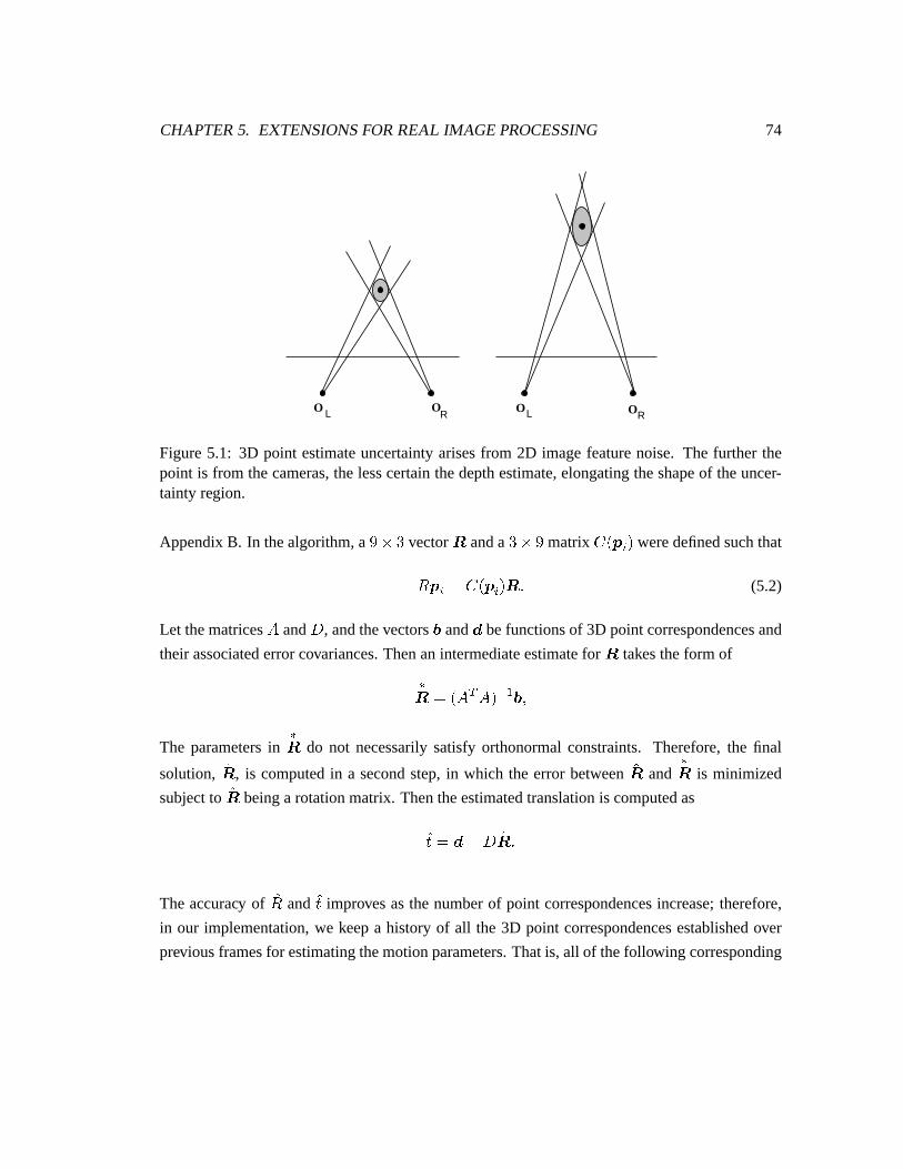
CHAPTER5. EXTENSIONSFORREAL IMAGE PROCESSING 74
L L RO OOR
O
Figure5.1: 3D point estimateuncertaintyarisesfrom 2D imagefeaturenoise. The further thepoint is from thecameras,thelesscertainthedepthestimate,elongatingtheshapeof theuncer-tainty region.
AppendixB. In thealgorithm,a lm;7+ vectorn anda +Q;:l matrix o L \ V S weredefinedsuchthat
N \ V �Fo L \ V S n f (5.2)
Let thematricesp and q , andthevectorsr ands befunctionsof 3D pointcorrespondencesand
theirassociatederrorcovariances.Thenanintermediateestimatefor n takestheform of
tnu� L pwvxp Szy Y r P
The parametersintn do not necessarilysatisfy orthonormalconstraints. Therefore,the final
solution, jn , is computedin a secondstep,in which the error between jn andtn is minimized
subjectto jn beinga rotationmatrix. Thentheestimatedtranslationis computedas
j{ ��s ^ q jn f
Theaccuracy of jN and j{ improvesasthenumberof point correspondencesincrease;therefore,
in our implementation,we keepa history of all the 3D point correspondencesestablishedover
previousframesfor estimatingthemotionparameters.Thatis, all of thefollowing corresponding
CHAPTER5. EXTENSIONSFORREAL IMAGE PROCESSING 75
point pairsareusedfor motionestimation:
h j\ V L $ SOP j\ V L � SOi(| h j\ V L � SOP j\ V L + SOi�| f�f�f | h j\ V L # ^ $ SOP j\ V L # SOi f
Themotionestimatesareupdatediteratively in abatchfashionateveryframeasmorecorrespon-
dencesbecomeavailable,improving trackingandstereomatchingefficiency. Onemayalsowant
to setamaximumonthenumberof framesthatapoint’shistoryis maintainedto limit theamount
of datastoragerequired.
5.1.2 AssessingEstimateAccuracy
Oncethe 3D motion parametersare available, featuretracking can switch from using the 2D
motionmodelof individual pointsasin Section3.3,to usingasingle,rigid 3D motionmodelfor
all points,asin Section3.4.
Usinggrosslyinaccuratemotionestimatesin the3D modelwouldsignificantlyreducethetrack-
ing effectivenessof thealgorithm.Thereforewe would only wantto switchto 3D trackingwhen
the estimatesaresufficiently accurate.However, it is difficult to assesswhenthe estimatesare
“goodenough.” Thestrategy thatwill beusedin ourexperimentsis to visually inspecttheerrorin
theestimatesaftersomeframesareprocessed,andmanuallydeterminewhen3D trackingshould
beused.
5.1.3 Modification to 3D Dynamic Model
The3D motionmodelpresentedin (3.4) assumedthat theexactmotion parametersareknown.
However, sincewe only have the estimates jNQL # S and j{ L # S , the error in the estimateswould
posesomeproblemsin thepredictionstepof theKalmanfilter. Thepredictedlocationanderror
covarianceof featurepointswouldbeverydifferentfrom thetruth,causingthetrackingalgorithm
to losetrackof many points.Hencethemotionmodelwill bemodifiedasfollows:
\ V L #@=�$ S � jN}L # S \ V L # S = j{ L # S =�~ V L # SOP (5.3)
where~ V L # S accountsfor theerrorin themotionmodel.
CHAPTER5. EXTENSIONSFORREAL IMAGE PROCESSING 76
Let
� NQL # S � NQL # SZ^ jNQL # SOP� { L # S � { L # SZ^ j{ L # SOPthen
~ V L # S � � NQL # S \ V L # S = � { L # SOP or
~ V L # S �Fo _ \ V L # Scb � n L # S = � { L # S f
If we assumethat ~ V L # S is a randomvectorwith zeromean,thepredictionis
j\ V L #A=�$�� # S ��jNQL # S j\ V L #�� # S = j{ f (5.4)
Usingthenotationin (5.2),thepredictionerrorcovarianceis
� V L #@=*$�� # S � jNQL # SO� V L #�� # S jN}L # S v =�o _ \ V L # Scb�����L #�� # S o _ \ V L # Scb v = ���OL #�� # SOP (5.5)
where���
and���
aretheerror covariancesof the estimatedrotationandtranslationparameters
respectively.
Accordingto themotionestimationalgorithm,weapproximatetheerrorcovariancesas
����L #�� # S � L p v p S y Y P (5.6)�Z��L #�� # S �q ����L #�� # S q�v f (5.7)
Themodificationsin (5.4)and(5.5)areprobablyinaccuratebecauseof anumberof reasons:
H1~ V L # S is mostlikely not zero-mean,
H � � L #�� # S and� � L #�� # S areapproximations,and
H sincewe do not know thetruevalueof\ V L # S , we canonly computeo _ j\ V L #�� # Scb insteadof
o _ \ V L # Scb .
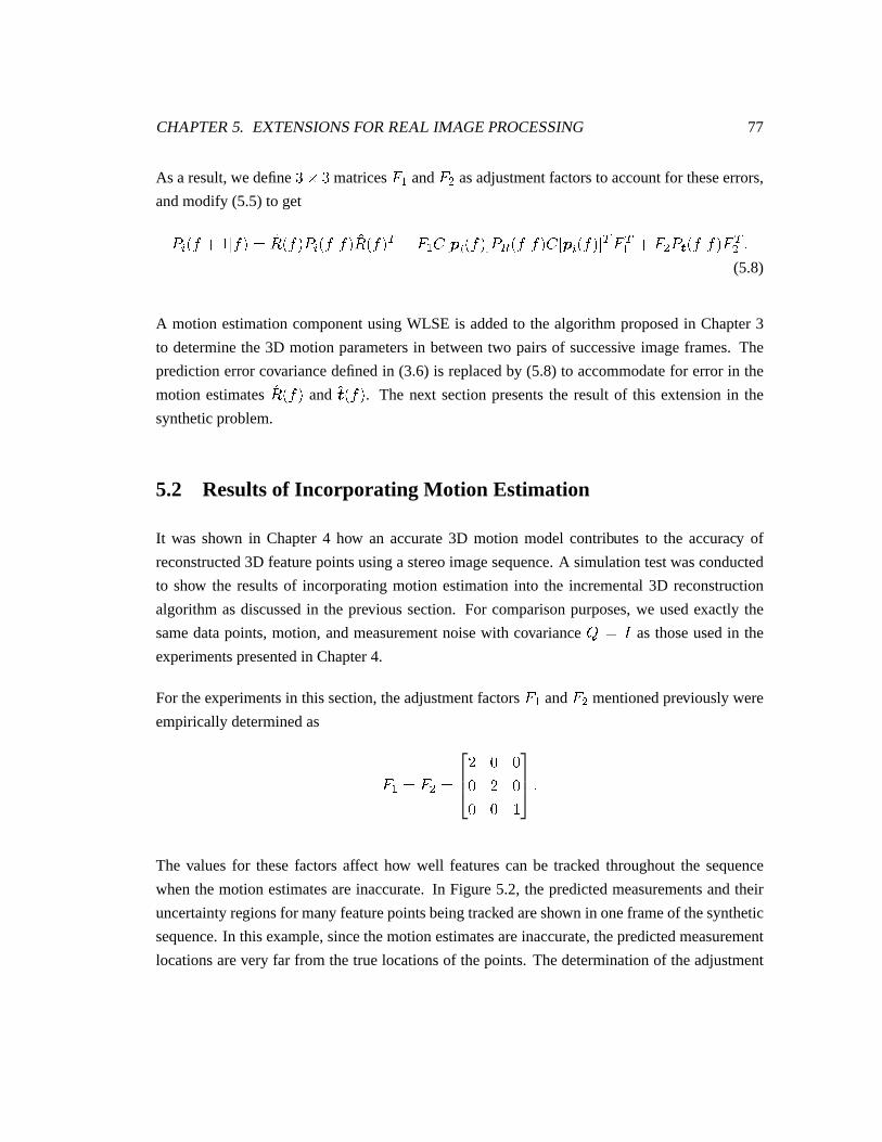
CHAPTER5. EXTENSIONSFORREAL IMAGE PROCESSING 77
As a result,wedefine +m;�+ matrices� Y and � d asadjustmentfactorsto accountfor theseerrors,
andmodify (5.5) to get
� V L #A=�$�� # S ��jNQL # SO� V L #�� # S jN}L # S v =�� Y o _ \ V L # Scb����wL #�� # S o _ \ V L # Scb v � vY =�� d ����L #�� # S � vd f(5.8)
A motion estimationcomponentusingWLSE is addedto the algorithmproposedin Chapter3
to determinethe 3D motion parametersin betweentwo pairsof successive imageframes. The
predictionerrorcovariancedefinedin (3.6) is replacedby (5.8) to accommodatefor error in the
motion estimates jN}L # S and jR�L # S . The next sectionpresentsthe resultof this extensionin the
syntheticproblem.
5.2 Resultsof Incorporating Motion Estimation
It was shown in Chapter4 how an accurate3D motion model contributes to the accuracy of
reconstructed3D featurepointsusinga stereoimagesequence.A simulationtestwasconducted
to show the resultsof incorporatingmotion estimationinto the incremental3D reconstruction
algorithmasdiscussedin the previous section. For comparisonpurposes,we usedexactly the
samedatapoints,motion, andmeasurementnoisewith covariance�,��! asthoseusedin the
experimentspresentedin Chapter4.
For theexperimentsin thissection,theadjustmentfactors� Y and � d mentionedpreviously were
empiricallydeterminedas
� Y �� d �� G GG � GG G $
f
The valuesfor thesefactorsaffect how well featurescan be tracked throughoutthe sequence
whenthemotion estimatesareinaccurate.In Figure5.2, the predictedmeasurementsandtheir
uncertaintyregionsfor many featurepointsbeingtrackedareshown in oneframeof thesynthetic
sequence.In thisexample,sincethemotionestimatesareinaccurate,thepredictedmeasurement
locationsarevery far from thetruelocationsof thepoints. Thedeterminationof theadjustment
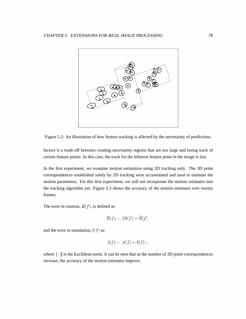
CHAPTER5. EXTENSIONSFORREAL IMAGE PROCESSING 78
Figure5.2: An illustrationof how featuretrackingis affectedby theuncertaintyof predictions.
factorsis a trade-off betweencreatinguncertaintyregionsthataretoo large andlosing track of
certainfeaturepoints.In thiscase,thetrackfor theleftmostfeaturepoint in theimageis lost.
In the first experiment,we examinemotion estimationusing2D trackingonly. The 3D point
correspondencesestablishedsolely by 2D trackingwereaccumulatedandusedto estimatethe
motionparameters.For this first experiment,we will not incorporatethemotion estimatesinto
the trackingalgorithmyet. Figure5.3 shows theaccuracy of themotion estimatesover twenty
frames.
Theerrorin rotation, �NQL # S , is definedas
�NQL # S � [ NQL # S�^ jN}L # S [andtheerrorin translation,�{ L # S as
�{ L # S � [ RkL # SZ^ jRkL # S [ Pwhere
[���[is theEuclideannorm. It canbeseenthatasthenumberof 3D pointcorrespondences
increase,theaccuracy of themotionestimatesimprove.
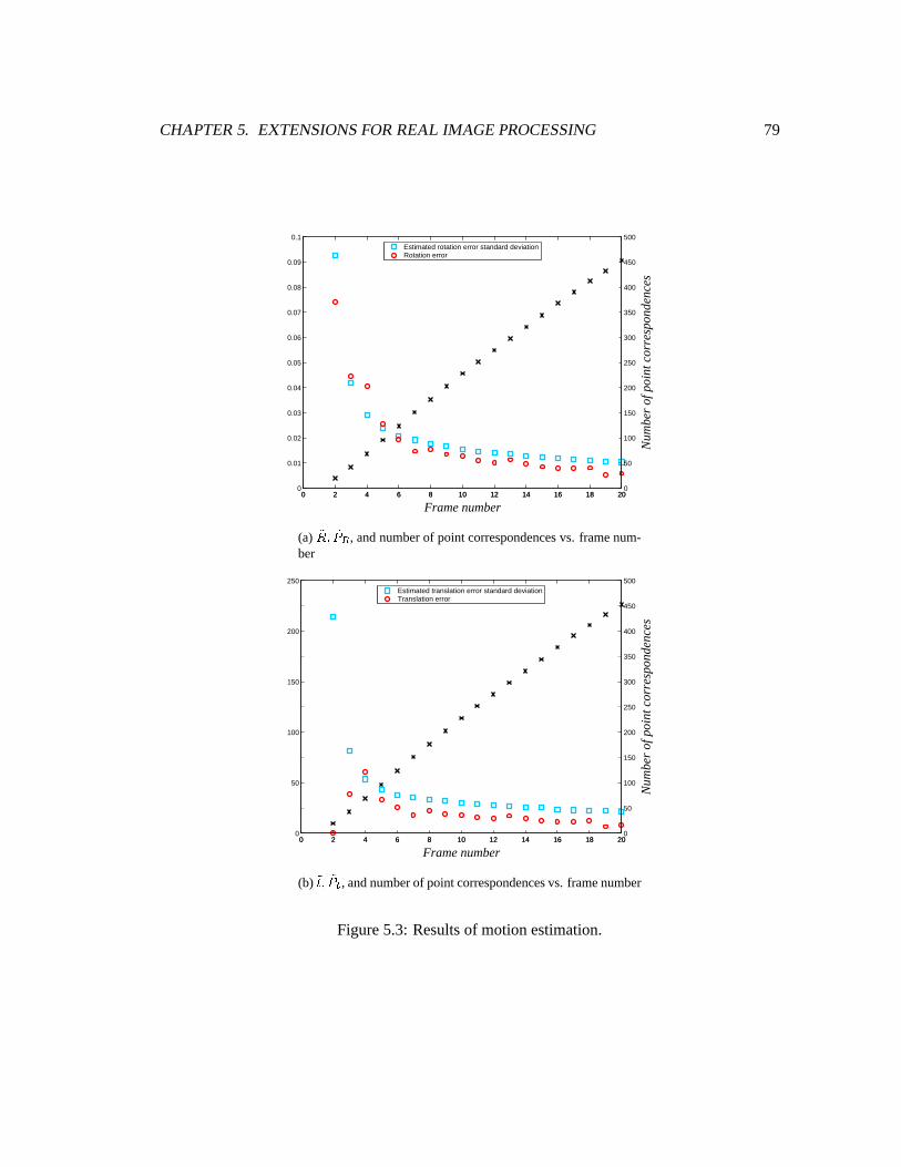
CHAPTER5. EXTENSIONSFORREAL IMAGE PROCESSING 79
0 2 4 6 8 10 12 14 16 18 200
0.01
0.02
0.03
0.04
0.05
0.06
0.07
0.08
0.09
0.1
Frame number
Estimated rotation error standard deviationRotation error
0 2 4 6 8 10 12 14 16 18 200
50
100
150
200
250
300
350
400
450
500
Nu
mb
er
of p
oin
t co
rre
spo
nd
en
ces
(a) ��5� �� � , andnumberof point correspondencesvs. framenum-ber
0 2 4 6 8 10 12 14 16 18 200
50
100
150
200
250
Frame number
Estimated translation error standard deviationTranslation error
0 2 4 6 8 10 12 14 16 18 200
50
100
150
200
250
300
350
400
450
500
Nu
mb
er
of p
oin
t co
rre
spo
nd
en
ces
(b) �� � ���� , andnumberof pointcorrespondencesvs. framenumber
Figure5.3: Resultsof motionestimation.
CHAPTER5. EXTENSIONSFORREAL IMAGE PROCESSING 80
Figure5.3alsoillustratestheaccuracy of theerrorcovariances,���wL #�� # S and
����L #�� # S , estimated
using(5.7). �� � L #�� # S and �� � L #�� # S approximatetheerror standarddeviation of themotionesti-
mates,where
�����L #�� # S � Trace_ ����L #�� # Scb�P
��Z��L #�� # S � Trace_ �Z��L #�� # Scb f
Theapproximatederrorstandarddeviationsshown in thefiguresdoseemto reflectthedistribution
of theerrorquitewell.
UsingFigure5.3asaguide,it wasdeterminedthatthe3D motionestimatesareaccurateenough
to beincorporatedinto themodified3D motionmodelin (5.3)afterframe6.
In thesecondexperiment,pointfeaturetrackingis switchedfrom usingatwo-dimensionalmodel,
asdescribedin Section3.3,to usingthemodifiedthree-dimensionalmodel,asdescribedin in the
previoussection,afterframe6 haselapsed.
The resultsof combiningboth 2D and 3D tracking to the reconstructionalgorithm are illus-
tratedin Figure 5.4. Comparedto the resultsin Figure 4.9, which were generatedusing 2D
trackingalone,theaccuracy of thereconstructedpoint featuresin Figure5.4hasbeenimproved.
Figure5.5(a)is a summaryof the resultsin this experiment.Thesummaryof resultsfrom Fig-
ure4.10for the2D trackingcasehasbeenduplicatedin Figure5.5(b)for easeof comparison.The
numbersof reconstructedpointsat eachframeasa resultof using3D motionestimatesfor fea-
turetrackingareslightly higherthanthoseof using2D trackingalone.Thesefigureseffectively
demonstratetheadvantageof usingan incrementalapproachto reconstructionasmoreaccurate
motionestimatesareavailablefor moreaccuratefeaturetracking.
5.3 Adding NewFeatures
In thesimulationexperimentspresentedin Chapter4, all of the featurepointswereassumedto
bevisible in all of theframesthroughoutthestereoimagesequence.This is of coursenot going
to bethecasefor realimagedatafor thefollowing reasons:
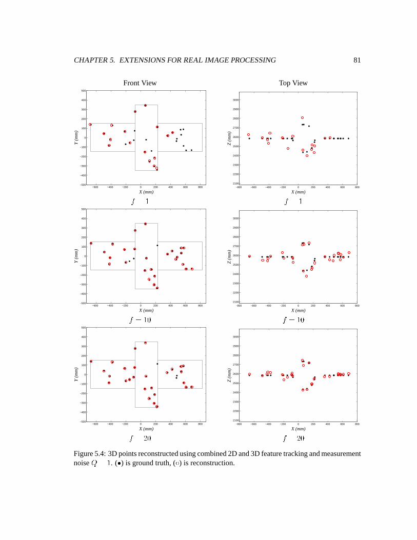
CHAPTER5. EXTENSIONSFORREAL IMAGE PROCESSING 81
FrontView TopView
−600 −400 −200 0 200 400 600 800−500
−400
−300
−200
−100
0
100
200
300
400
500
X (mm)
Y (
mm
)
−800 −600 −400 −200 0 200 400 600 8002100
2200
2300
2400
2500
2600
2700
2800
2900
3000
X (mm)
Z (
mm
)
#E�F$ #E�F$
−600 −400 −200 0 200 400 600 800−500
−400
−300
−200
−100
0
100
200
300
400
500
X (mm)
Y (
mm
)
−800 −600 −400 −200 0 200 400 600 8002100
2200
2300
2400
2500
2600
2700
2800
2900
3000
X (mm)
Z (
mm
)
#E�$"G #��F$"G
−600 −400 −200 0 200 400 600 800−500
−400
−300
−200
−100
0
100
200
300
400
500
X (mm)
Y (
mm
)
−800 −600 −400 −200 0 200 400 600 8002100
2200
2300
2400
2500
2600
2700
2800
2900
3000
X (mm)
Z (
mm
)
#E��"G #��F�"GFigure5.4:3D pointsreconstructedusingcombined2D and3Dfeaturetrackingandmeasurementnoise ��$ . ( H ) is groundtruth, ( I ) is reconstruction.
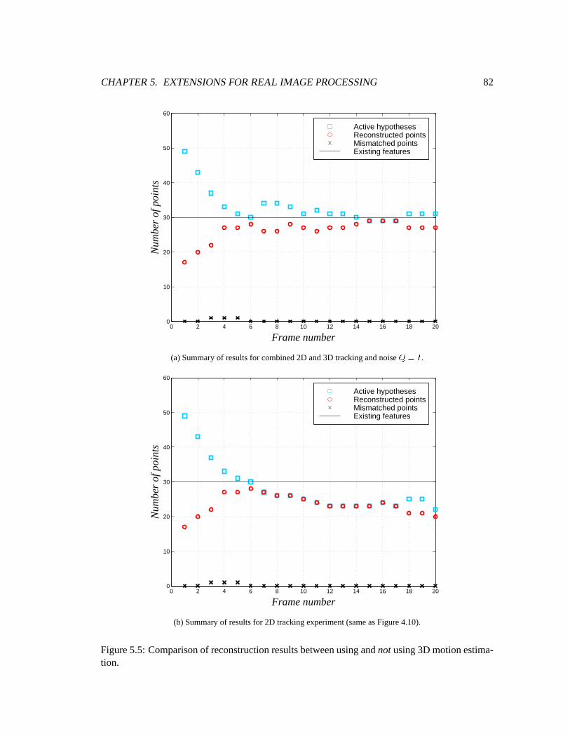
CHAPTER5. EXTENSIONSFORREAL IMAGE PROCESSING 82
0 2 4 6 8 10 12 14 16 18 200
10
20
30
40
50
60
Frame number
Nu
mb
er
of p
oin
ts
Active hypothesesReconstructed pointsMismatched pointsExisting features
(a)Summaryof resultsfor combined2D and3D trackingandnoise 74@¡ .
0 2 4 6 8 10 12 14 16 18 200
10
20
30
40
50
60
Frame number
Nu
mb
er
of p
oin
ts
Active hypothesesReconstructed pointsMismatched pointsExisting features
(b) Summaryof resultsfor 2D trackingexperiment(sameasFigure4.10).
Figure5.5: Comparisonof reconstructionresultsbetweenusingandnotusing3D motionestima-tion.
CHAPTER5. EXTENSIONSFORREAL IMAGE PROCESSING 83
H Dependingonthecharacteristicsof thefeatureextractorandthecurrentreflectanceproper-
tiesof theobject,theselectionof featurepointsextractedby thefeatureextractorwill vary
from frameto frame.Thereforenotall featureswill beconsistentlypresentthroughoutthe
wholesequence.
H As theobjectundergoesmotion,somepartsof theobjectbecomeself-occludedwhile oth-
ers re-appearfrom self occlusion. New featuresthat werepreviously not visible during
the initialization stageof the algorithmwill appearanytime during the executionof the
trackingandreconstructionalgorithm.
In additionto thesetwo cases,it shouldalsobenotedthatthefeaturetrackerspresentedin either
Section3.3 or Section3.4 are not perfect. They may lose track of somefeaturepoints even
thoughthey existedin previousimageframes.In orderto maintaina dense3D representationof
theobjectthroughoutthewholeimagesequence,it is importantto initialise new tracksfor both
thenewly appearedfeaturesandthepreviously lost features.
For any 2D imagefeaturepoint appearingin the left imageframeat frame # , if theredoesnot
exist any stereomatchinghypothesisthat is madeup of thatpoint, it is considereda new feature
point. If epipolarconstraintsaresatisfied,new stereomatchinghypothesesconsistingof that
point andotherimagepointsfrom theright imageframesarecreated.
Usingthenotationpresentedin Chapter3, new tracksarecreatedusingthefollowing criterion:
For each¢Z£¤ L # SOP if ¥8¦ L # P�§�P]¨�S�©8¨�P create¥8¦ L # P�§�P]¨�S if ª¬« LO§�P]¨�S �F f
By usingthis strategy, lost featureswill consistentlybereplacedandnew featuresthatappearin
thescenewill alsobeconsideredfor reconstruction.Theextensionwill beappliedto processa
realimagesequence.
5.4 Real Image Sequence
In this section,we describea 3D reconstructionexperimenton a real stereoimagesequence
capturedin a laboratoryenvironment.Theimageswereprovidedby MacDonaldDettwilerSpace
andAdvancedRoboticsLtd.
CHAPTER5. EXTENSIONSFORREAL IMAGE PROCESSING 84
A modelof a typical dockinginterfacefor spacemodulesis seatedon the endof a robot with
six degreesof freedom.A pair of Pulnix CCD cameraswith an imageresolutionof ®"�"G¯;:.�°"Gpixels is mountedon a stationaryplatformsomedistanceaway from the robot. Currently, only
theobjectmodelcanbemovedaround,but eventuallythecameraswouldalsobeallowedto move
whenasecondrobotis available.Figure5.6shows therobotwith theobjectmodelon theend.
Thecameraswerecalibratedby MDR andtheparametersareshown in AppendixA. Theeffects
of opticaldistortionarenegligible, thereforethedistortionfactorhasbeenignoredin computing
thestereosystem’s epipolargeometry.
We selecta sequenceof twentysuccessive stereoimagepairsandapply cornerdetectionon all
forty imagesusingthealgorithmdescribedin [26] 1. In areal–timeapplication,featureextraction
would actuallybe carriedout for eachstereoimagepair asit becomesavailable. However, for
experimentationpurposes,thirty of themostprominentcornerfeaturesareextractedfrom eachof
theimagesin thewholestereosequenceasapre-processingstep.Theidentifiedfeaturelocations
will serve asinput to theincrementalreconstructionalgorithm.
Threestereoimagepairsfrom thesequence,alongwith theextractedfeaturepoints,areshown
in Figure5.7. Becauselarge regionsof the imagesareblack, they have beencroppedto a size
of �"°"G±;��"°"G pixels for betterpresentation.As the imagesshow, the amountof objectmotion
during the twenty elapsedframesis quite significant. As a result,many of the featurepoints
eitherbecomeoccludedor disappeareddueto the featureextractor’s inability to detectthemin
differentlightingconditions.Thismayposechallengesfor longtermtracking.Adjustmentsto the
parametersof thefeatureextractoror choosingadifferentonemaycorrectthisproblem;however,
comprehensivestudiesonfeatureextractionis outsidethescopeof thisthesis.Furthermore,many
featurepointsarisefrom shadows andspecularreflection,which oftendo not conformto stereo
epipolargeometryor rigid bodymotion.Wecanseethatin arealimagesequencesuchasthis,an
actualfeaturemaynot bevisible or detectedin boththeleft andright imagesat thesameframe.
Hencewe shouldbeexpectingto seemany of thesepointsrejectedfrom thelist of reconstructed
3D points.
Theexperimentonthissequencewill examinetheperformanceof theincrementalreconstruction
algorithmusingtwo-dimensionaltrackingonly. Themotionmodelerrorcovariancesareempir-
1An implementationof this cornerdetectorandits associatedKLT FeatureTracker [56] is publicly availableathttp://robotics.Stanford.EDU/ ² birch/klt
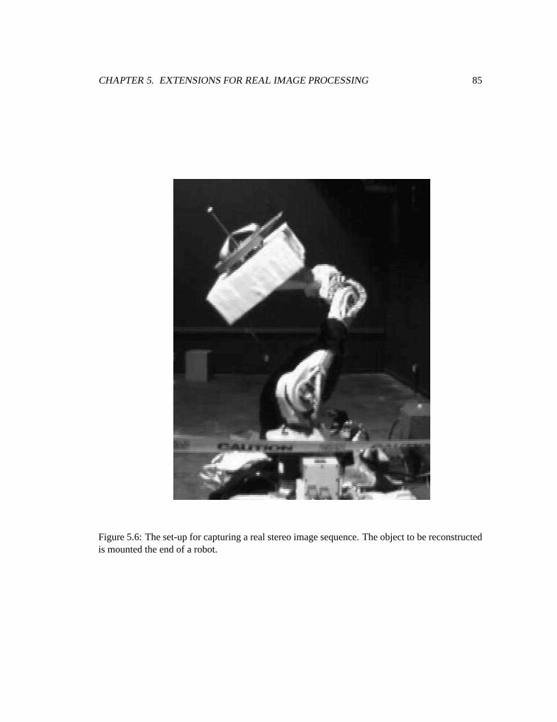
CHAPTER5. EXTENSIONSFORREAL IMAGE PROCESSING 85
Figure5.6: Theset-upfor capturingarealstereoimagesequence.Theobjectto bereconstructedis mountedtheendof a robot.
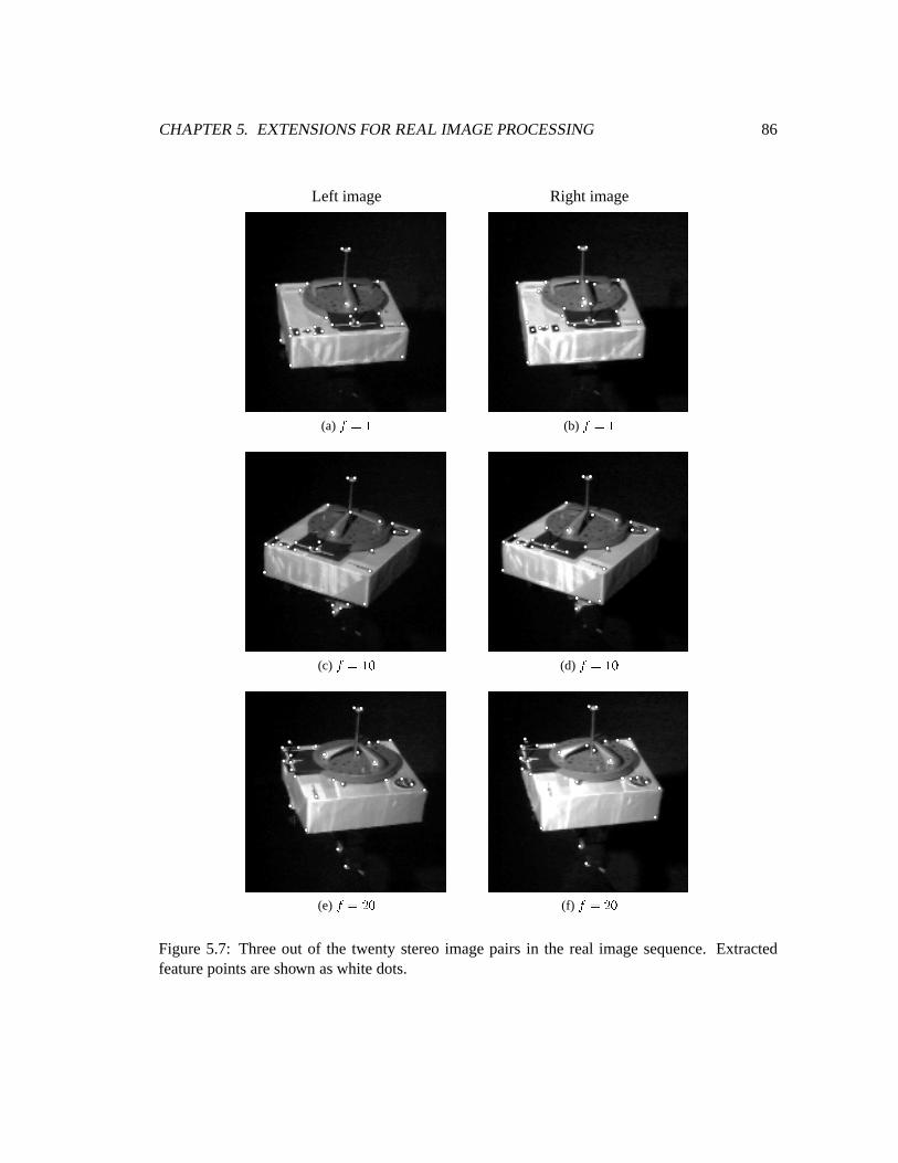
CHAPTER5. EXTENSIONSFORREAL IMAGE PROCESSING 86
Left image Right image
(a) 35476 (b) 35476
(c) 354:6´³ (d) 35476�³
(e) 354:9´³ (f) 35479�³Figure5.7: Threeout of the twenty stereoimagepairs in the real imagesequence.Extractedfeaturepointsareshown aswhite dots.
CHAPTER5. EXTENSIONSFORREAL IMAGE PROCESSING 87
ically determinedby visual inspectionas $"�"! , µ"! and ! respectively in pixel units for thezero,
first, andsecondorderestimators.
For theexperiment,stereomatchinghypothesesaregeneratedfrom thefeaturepointsat frame1.
Thesepointsaretrackedover thetwentyframeswhile thestereomatchinghypothesesaretested.
Featurepointsthatdo not constituteexisting stereomatchinghypothesesat eachframeareused
to replacetheonesthathave beenlost or occluded.Figure5.8shows thereconstructedpointsat
threedifferenttime frames.Sincethenumberof pointsis few, it wouldbedifficult to convey any
senseof shapeby plotting thepointsalone.In orderto demonstratetheresultsmeaningfully, the
reconstructedsetof pointsareprojectedbackontotheir respective images.
In the first pair of images(Figures5.4, 5.4), it canbe seenthat someof the extractedfeature
points,asshown in Figure5.7, that seemto be obvious matchesarenot reconstructed.This is
becausetheonly constraintusedfor matchingat this point is theepipolarconstraint.Therefore
someof the featurepoints in the left imagemay have several matchingcandidatesin the right
image.Moreover, asmentionedbefore,many of theextractedfeaturepointsresultfrom shadows
andspecularreflection,whichmaynot satisfytheepipolarconstraint.
An interestingthing to noteis that in Figures5.8(c)and5.8(d),two featurepointsthatoriginate
from the robot becomereconstructed.Thesetwo points do not belongto the object of inter-
estandcertainlydo not have motion consistentwith thosebelongingto the object. Thesetwo
reconstructedpointswould becomeoutliersif they areusedfor motionestimationpurposes.
A summaryof thenumberof activestereohypothesesandthenumberof reconstructedpointsover
the twenty framesis presentedin Figure5.9. Thenumberof active hypothesesdo not decrease
over time. Onepossibleexplanationis thatmany featurepointsdisappearfrom frameto frame
andarenotpresentlongenoughfor themto betrackedconsistently. Henceateachframe,features
aretreatedasif they have newly enteredtheimagessuchthatadditionalhypothesesarecreated.
The numberof reconstructedpoints in this experimentis very low comparedto the resultsof
the syntheticdata. Therearealsosomemismatches.This may suggestthat stereoandmotion
constraintsalonearenot sufficient to resolve many of thematchingambiguitiesin a real image
sequence.
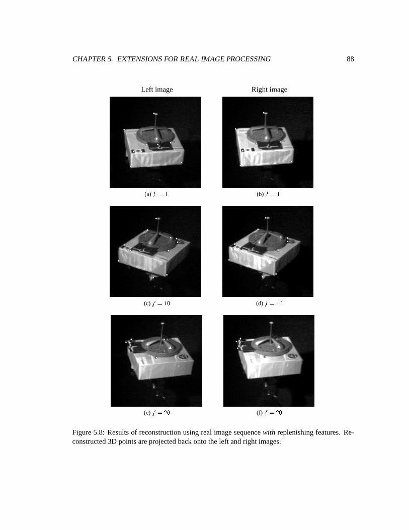
CHAPTER5. EXTENSIONSFORREAL IMAGE PROCESSING 88
Left image Right image
(a) 38476 (b) 35476
(c) 35476�³ (d) 3¶4:6´³
(e) 35479�³ (f) 35479�³Figure5.8: Resultsof reconstructionusingreal imagesequencewith replenishingfeatures.Re-constructed3D pointsareprojectedbackontotheleft andright images.
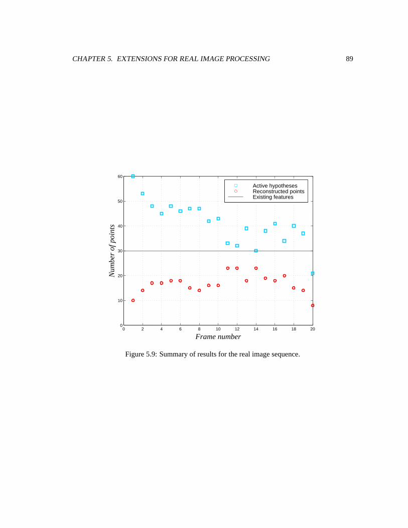
CHAPTER5. EXTENSIONSFORREAL IMAGE PROCESSING 89
0 2 4 6 8 10 12 14 16 18 200
10
20
30
40
50
60
Frame number
Nu
mb
er
of p
oin
ts
Active hypothesesReconstructed pointsExisting features
Figure5.9: Summaryof resultsfor therealimagesequence.

CHAPTER5. EXTENSIONSFORREAL IMAGE PROCESSING 90
5.5 Conclusion
The experimentsdiscussedin Section5.2 usingsyntheticdatacombinemostof the important
elementsof thework in this thesis.Theresultsarequiteconvincingandsuggestthattheconcepts
presentedso far are feasibleandareworthwhile for investigation. Of course,nearlyan ideal
situationhasbeencreatedusingthe syntheticdatabecauseall of the featuresarevisible at all
timesandthemotionof theobjectconforms.tothemotionmodelusedfor thecomputation.When
appliedto arealimagesequence,theresultsarenotassatisfactory, whichsuggestthatthereis still
a lot of roomfor improvementin orderfor theincrementalreconstructionalgorithmto beusable
in a real-timeapplication.A moredetailedanalysisof thelimitationsandpossibleimprovements
of thecurrentwork will beprovidedin thenext chapter.
Chapter 6
Conclusions
Thischaptersummarisesthemajorcontributionsof this thesisandidentifiesthelimitationsin the
currentwork. A setof possibilitiesfor futurework is listed.
6.1 ThesisAchievements
In this thesis,I have proposedanincrementalalgorithmfor usinga sequenceof stereoimagesto
reconstruct3D featurepointsbelongingto a rigid object.
Whatmakestheproblemof 3D reconstructiondifficult is themerefactthatit encompassesmany
differentindividual subproblems,from featuretrackingto stereomatchingto motionestimation,
all of whichhavenoperfectsolutions.It is alwayselegantto addressoneissueatatime,however,
in arealworld application,all of theseissuesexist andhaveto beconsidered.In thisthesis,I have
demonstratedhow thesesubproblemsaresolved simultaneouslyin oneunified framework. The
approachis incrementalin thesensethattheiterativeprocessof stereomatching,featuretracking,
andmotionestimationenableseachsubproblemto provide moreconstraintsfor eachotherand
enhancesthesolutionprocess.Althoughthework in this thesisfallsshortof aproductionsystem
thatcouldbeusedin areal-timeapplicationin termsof accuracy andspeed,thetheoreticalframe-
work hasalreadybeenestablishedandfuturework becomesamatterof enhancingtheindividual
componentswithin that framework. The feasibility andpotentialof theproposedalgorithmhas
91
CHAPTER6. CONCLUSIONS 92
beenprovenby theresultsshown in Chapter5.
Thefollowing list highlightssomeof theothercontributionsmadeby this thesis:
H Featurematchingis specificallyaddressedandintegratedinto the system,asopposedto
beingignoredasin somepreviouswork [65, 67].
H A lot of pasteffort is aimedatsolvingthefeaturecorrespondenceproblemcompletelyin a
singlepairof images;we do this in anincrementalfashion.
H Most pastresearchusevery complex, computationallyintensive stereomatchingmethods
suchasdynamicprogramming[39] or graphmatching[15]; sinceonly stereoandmotion
constraintsareusedin theproposedmethod,wetookadvantageof thespeedof theKalman
filter for dynamicestimationof a low dimensionalproblem.Processingspeedis very im-
portantin realtimeapplications.Thecurrentimplementationin Matlab1 requiresaboutfive
secondsfor processingeachpair of stereoimages.It is believedthatanimplementationin
acompilerlanguagesuchasC wouldgreatlyimprove thespeedof thecurrentsystem.
6.2 Limitations and Futur eWork
Not too surprisingly, thework in this thesishasby no meansaddressedall theissuesnor doesit
provide an idealsolutionto the3D reconstructionproblem.Many detailshave beenconsidered
but areintentionallyomitted in this thesisbecausethey requiremoreextensive researchthat is
not feasiblegiventhetime constraintson this thesis.
Thefollowing list of potentialfutureresearchis notmeantto beexhaustive; however, it represents
the more significanttasksrequiredbeforea productionquality incremental3D reconstruction
systemcanbeachieved.
Local feature matching: The approachthat this thesishas taken for featurematchingis to
only useepipolarandmotion constraintsto evaluatepotentialmatchingcandidates.The
strengthsof this approachare that it can generallybe appliedto any typesof features,
1A high level, interpretedprogramminglanguagefor technicalcomputingand visualizationdevelopedby TheMathWorksInc.
CHAPTER6. CONCLUSIONS 93
avoiding thepitfalls whenlighting conditionsandgeometricdistortioncausethe features
to look very different,andthecomputationalcostis very low. However, asthe resultson
thereal imagesequencein Chapter5 suggest,this approachis alsooneof theweaknesses
of thework in this thesis.Someof thefeaturesthatcaneasilybematchedby, for example,
templatematching[35, 36], arenot distinguishedby the currentapproachandtreatedas
ambiguities.Sinceonly featurepointswith only onematchingcandidatearereconstructed,
many of thesematchingambiguitiesarecarriedforward to future framesashypotheses.
If we employ someotherexisting local matchingtechniquessuchasareacorrelation,as
describedin Chapter2, thecorrectmatchingratewould probablyincrease.To keepcom-
putationalcostdown, oneoption is to integratea simpleandcrudematchingalgorithm
to the existing framework, which would narrow down the numberof hypothesesandthe
remainingambiguitiesmaybeleft for themotionconstraintsto resolve.
Global constraints: Currently, no globalconstraints,suchasuniquenessanddisparitysmooth-
ness[4, 5] areimposedonthestereomatchingcomponentof thework. Onepossiblesimple
extensionis to enforcetheone-to-onerelationshipbetweenfeaturesin theleft andtheright
images.In the currentset-up,eachfeatureon the left imageis ensuredto have only one
matchingfeaturefrom the right. However, the reverseis not imposed.Someof the fea-
turemismatches,asseenin Chapter5, mayhave beenavoidedif wealsoenforcethateach
featurepoint in theright imagehasonly onematchfrom theleft image.
Robust motion estimation: Although the goal of the researchin this thesisis not to acquire
accuratemotion estimatesfor the objector camerasin the scene,dueto the dependency
of thetrackingalgorithmson theseestimates,a morerobustmotionestimatoris crucial to
furtherrestrictthesearchregionsfor point featuresin thenew frames.
Sincethe3D motionestimationalgorithmusedin this thesisperformsleastsquaresfitting
of reconstructed3D featurepoints,outliersin thedatasetswould degradetheaccuracy of
the motion estimates.The strict requirementin the incrementalalgorithmthat only fea-
ture pointswith only onestereomatchinghypothesisbe reconstructedreadily eliminates
someof the possibleoutliers. However, undersomecircumstances,mismatchesarestill
possible,leadingto the creationof incorrect3D featurepoints. Moreover, asseenin the
experimentsinvolving realimagedata,someof thereconstructedfeaturepointsdo notbe-
long to therigid bodyundergoingmotion. In thesecases,anotheroutlier rejectionscheme,
for example,aRANSAC typeapproach[80], is necessaryfor robustmotionestimation.
Sameframe iterati ve estimation: 3D reconstructionin theproposedframework involvesesti-
CHAPTER6. CONCLUSIONS 94
matingmotionanddepthiteratively, with theresultsof eachprocessbootstrappingtheother
atsuccessive imageframes.Thismethodis fastbut theaccuracy of estimatesat thecurrent
framecanfurther be improved if this iterative processis alsoperformedwithin thesame
pair of imageframes. In [66], this techniqueis usedwithin the context of a monocular
sequence,andcouldeasilybeextendedto a stereosequence.In otherwords,motionesti-
matesarisingfrom the reconstructed3D pointsin an imagepair canbeusedto constrain
matchingof other featuresin the samepair, which in turn would generatebettermotion
estimates.In real-timeprocessing,this proceduremayberepeatedwithin thesameimage
pairanumberof timesdependingonthevideoframerate,motionof object,computational
speed.
Motion limitations: As someresearchers,for instance,WaxmanandDuncan[70], havenoticed,
thereis a setof motionsfor which a stereoimagesequenceis ineffective in disambiguat-
ing stereofeaturecorrespondences.In thecontext of thework presentedin this thesis,the
multiple hypothesisstereoandtemporalmatchingalgorithmwill noteliminatefalsestereo
matchesfor thesekinds of objectmotion. Oneexampleis puretranslationparallelto the
epipolarlines of the stereocameras.Anotherwould be pure rotationalong the object’s
vertical axiswhenepipolarlineshorizontal. A moredetailedanalysiswill be requiredto
identify this setof motionsto betterunderstandthelimitationsof theproposedreconstruc-
tion method.
Criteria for using 3D motion model: Onelimitation in thecurrentwork is thatweneedto em-
pirically determinewhenthemotionestimatesis sufficiently accurateto beusedin athree-
dimensionalmotion model. Ideally, this processshouldbe doneautomaticallywithout
manualcalibration.Oneadhocsolutionis to setanabsolutethresholdfor themotiones-
timateuncertaintyunderwhich three-dimensionalfeaturetrackingwill commence.How-
ever, establishingareasonablethresholdwouldagainrequiremanualcalibration.Ideally, a
motionestimateis sufficiently accuratewhenduringtracking,theuncertaintyregionof any
predictedfeaturedoesnot overlapwith featuresotherthanthetruematch.This condition
will requirea criterion that is basedon themotionestimate,its uncertainty, the locations
of the features,and the distancesamongthe different features. Someefforts have been
initiatedto explorethis option,but furtherinvestigationis required.
Motion modelling: Thecurrent3D motionmodelin Section3.4 assumesthat thereis a single
motion that is definedwith respectto the cameraframeof reference.This modelwould
besufficient if only thecamerais in constantmotion,but is inadequateif theobjectin the
CHAPTER6. CONCLUSIONS 95
scenehasmorecomplicateddynamicssuchasprecession.Perhapsa bettermotionmodel
suchastheLCAM modelmentionedin Section2.5shouldbeused.
Misseddetectionand occlusion: Oneof themajorchallengesof onlinefeaturetrackingis deal-
ing with thesporadicappearanceanddisappearanceof featurepointsin thesequencedue
to eitherfailureof thefeatureextractionprocessor temporaryocclusion.Althoughby re-
plenishinglost features,asdescribedin Section5.3, we cansuccessfullyinitialise a new
track for a featurethathasre-appearedaftera shortperiodof absence,a continuoustrack
will increasethecertaintyof thatfeaturepoint’s 3D position.Batchprocessingapproaches
suchas[58] have theadvantageof “looking into the future” andinterpolatethe locations
of featuresthatarelikely to have disappearedtemporarily. For onlineprocessing,thereare
threequestionsthathave to beanswered:
1. How to determinewhetherthedisappearanceof a featureis the resultof missedde-
tectionor temporaryocclusion,or it beinga falsefeature?
2. How many moreframesdo we have to wait beforewe stoptrackinga disappeared
feature?
3. How to predicta feature’s locationin thenext frameif it is not visible in thecurrent
frame,andhow to determinetheprediction’s uncertainty?
[63] suggestsa statisticalmeasurecalledthesupportof existencewhich addressesthefirst
two issuesof the above list, but it hasno mentionof the last one. Sincethe goodnessof
fit criteria (3.12)developedin Section3.5 is inspiredby thework in [63], someattempts
weremadeto adoptthesupportof existencemeasureinto thework in this thesis.However,
more investigationandexperimentationis still required. Anotherpossibility is to assess
the actualuncertaintyof the missingfeaturepoint’s 3D location to answerthe first two
questions.Onesolutionthat wasconsideredfor the last questionin the list is simply to
usethe3D motionestimateto extrapolatethefeaturepoint’s location,which maybecome
increasinglyuncertainif thefeaturecontinuesto beundetected.
Complete +"·"Gg¸ reconstruction: Oneof the original motivation for developingan incremental
reconstructionframework wasit’s potentialfor constructinga complete+"·"G ¸ representa-
tion of an objectusinga stereoimagesequencealonewithout the separatestepof view
registration.This would requireaccuratemotionestimatesandrobustmethodsof dealing
with occlusion,sothat thefeaturepointscanbetrackedwith high levelsof certaintyeven
if they areoccludedby theobjectitself, until they re-appearagainfrom behindtheobject.
CHAPTER6. CONCLUSIONS 96
Although the resultspresentedin this thesisarefar from achieving this goal, it is still an
interestingdirectionto pursue.
As an endingnote,onelessonthat hasbeenlearnedby the endof this thesisis that regardless
of the amountof researchthat hasalreadybeendonein the pasttwo decades,the problemof
3D reconstructionfrom digital imagesstill remains,to someextent,unsolved. Therearemany
issuesandpossibilitiesyet to be consideredandexplored. From readingexisting literatureand
personalexperience,it hasbeenobserved that it is difficult to developa computervision system
that is completelyautonomouswithout any humancalibrationof parametersor otherkinds of
intervention. It becomeshardnot to marvel at thecomplexity of thehumanvisualandpercep-
tual systemswhich, for mostpeople,canaccomplishmany of thetasksmentionedin this thesis
without muchconsciouseffort. Nevertheless,the currentbenefitsof computervision in many
applicationswarrantthecontinuoussearchfor bettersolutions.Hopefully, thesesolutionswould
soonreacha level of robustnessfor commonusein theaerospaceindustry.
Appendix A
CameraParametersFor Simulations
and Experiments
TableA.1 andTableA.2 liststheintrinsicandextrinsicparametersof thecamerasystemsusedfor
generatingthesyntheticandcapturingthe real imagesrespectively. Theparametersaredefined
asfollow [1]:
¹ : radialdistortionL $"º mm
d S#�» : focal length(mm)L ��¼ P]½ ¼ S : principalpoint (pixels)LO¾À¿kP�¾ÂÁkS
: effective pixel sizes(mm)
p}Ã : camerarotationmatrix
rÂÃ : cameratranslation(mm)
97
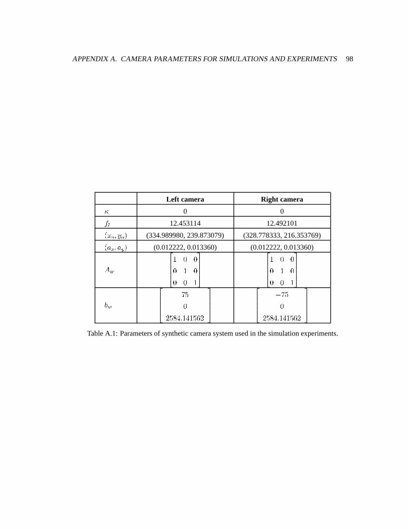
APPENDIXA. CAMERA PARAMETERSFORSIMULATIONSAND EXPERIMENTS 98
Left camera Right camera¹ 0 0
#�» 12.453114 12.492101L ��¼ P]½ ¼ S (334.989980,239.873079) (328.778333,216.353769)LO¾ ¿ P�¾ Á S(0.012222,0.013360) (0.012222,0.013360)
p�Ä$ G GG $ GG G $
$ G GG $ GG G $
Å Ä®"µG
�"µ"°�. f $�.�$"µ"·"�
^ ®"µG
�"µ"°�. f $�.�$"µ"·"�TableA.1: Parametersof syntheticcamerasystemusedin thesimulationexperiments.
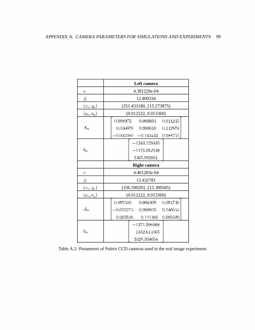
APPENDIXA. CAMERA PARAMETERSFORSIMULATIONSAND EXPERIMENTS 99
Left camera¹ 4.381229e-04
#�» 12.409334L ��¼ P]½ ¼ S (351.433180,215.273875)LO¾ ¿ P�¾ Á S(0.012222,0.013360)
p�ÄG f l"l"°"l"®"� G f G"G"l"°"+�. G f G�.".���.�µ^ G f G"$"·"G"®"G G f l"°"l"·"$"G G f $�.��"°"®"°^ G f G�.��"+"°"G ^ G f $�.�+�.".�� G f l"°"°"®"µ"$
Å Ä^ $"��.�+ f $"�"·"+"+"µ^ $"$"®"µ f µ"µ"�"$"+"°��.�·"µ f l"+"�"°"+"$
Right camera¹ 4.461283e-04
#�» 12.432781L ��¼ P]½ ¼ S (336.590293,215.389585)LO¾ ¿ P�¾ Á S(0.012222,0.013360)
p�ÄG f l"l"µ"µ"G"G G f G"G"$"l"G"l G f G"l�.�®�.�·^ G f G"$"µ"�"®"µ G f l"°"l"l"µ"µ G f $�.�G"µ"µ"µ^ G f G"l"+"µ"�"· ^ G f $�.�$"+"·"l G f l"°"µ"µ"�"l
Å Ä^ $"�"®"$ f µ"l"°"l"·"°^ $"$"°"� f ·"$�.�G"·"µ�"µ"�"° f +"G�.�·"µ�.
TableA.2: Parametersof PulnixCCD camerasusedin therealimageexperiment.
Appendix B
WeightedLeast SquaresEstimation of
3D Motion
This appendixoutlinesthe algorithm that is usedin this thesisfor estimationthe 3D motion
parametersasmentionedin Section5.1.TheWeightedLeastSquares(WLS) algorithm,proposed
by Wenget. al. [79], is a motionestimationalgorithmthat takesinto accounttheuncertaintyin
eachof theL B P C P D S directionsof the 3D featurepointsthatarereconstructedfrom 2D image
features.
In orderto obtainaccuratemotionparameters,adifferentweightis placedon eachof thecoordi-
natewhencomputingtheleastsquaressolutionto themotionestimationproblemusinginaccurate
3D featurepoints,asformulatedin (5.1).
To simplify notation,wewill use\ V to represent
\ V L # S and\�ÆV to represent
\ V L #Ç=�$ S respectively.
Let È V and È Æ V betheerrorsin j\ V and j\ Æ V respectively, themotionmodelis writtenas
j\ Æ V =�È ÆV � NQL j\ V =1È V S = R� NQL j\ V S = R = N È V ^ È Æ V f
Assumingthat È V and È Æ V areuncorrelated,thecovarianceof theresidualN È V ^ È Æ V is
É V � NQ� V N v = � ÆV P
100
APPENDIXB. WEIGHTEDLEAST SQUARESESTIMATION OF 3D MOTION 101
andfor smallinter-framemotion,É V canbeapproximatedas
É V � � V = � ÆV f
LettingÉ y YV betheweightingmatrix, theWLS objective function to minimize in estimatingthe
motionparametersis
KMLONQPORTS �UVXWZY LON j
\ V = Rw^ \ Æ V S v É y YV LON j\ V = Rw^ \ Æ V S f (B.1)
A closed-formsolutionto thisobjective functionis reportedin [79], andit is basedontheMatrix-
WeightedCentroidCoincidence(MWCC) Theorem.It statesthatif jN and jR minimize(B.1), the
matrixweightedcentroidsof h jN \ V = jRai and h \�ÆV i coincide:
UVXWZY É
y YV L jN j\ V = jR�S �UVXWZY É
y YV j\ Æ V f (B.2)
In orderto decoupleN
andR
andfind a non-iterative solution,we needto expresstheobjective
functionin (B.1) asa linearexpressionof theparametersinN
.
For any rotationmatrixexpressedin termsof its row vectors
N �n v Yn vdn vÊ
P
we defineavector
n�Ën Yn dn Ê
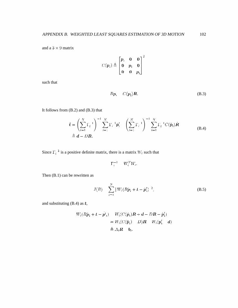
APPENDIXB. WEIGHTEDLEAST SQUARESESTIMATION OF 3D MOTION 102
anda +�;�l matrix
o L \ V S Ë\ V Ì ÌÌ \ V ÌÌ Ì \ V
v
suchthat
N \ V �Fo L \ V S n f (B.3)
It follows from (B.2) and(B.3) that
jR �UVXWZY É y
YVy Y UVXWZY É y
YV j\ Æ V ^UVXWZY É y
YVy Y UVXWZY É y
YV o L j\ V S jnËÍs ^ qÎn f
(B.4)
SinceÉ y YV is apositive definitematrix, thereis amatrix Ï V suchthat
ÉMy YV �FÏ vV Ï V fThen(B.1) canberewritten as
K�LONQS �UVXWZY[ Ï V LON j\ V = Rw^ j\ Æ V S [ d P (B.5)
andsubstituting(B.4) asR,
Ï V LON j\ V = R�^ j\ Æ V S �FÏ V L o L j\ V S nÐ=1s ^ q�n ^ j\ Æ V S�FÏ V L o L j\ V SZ^ q S n ^ Ï V L \ Æ V ^ s SËÑp V n ^ r V f
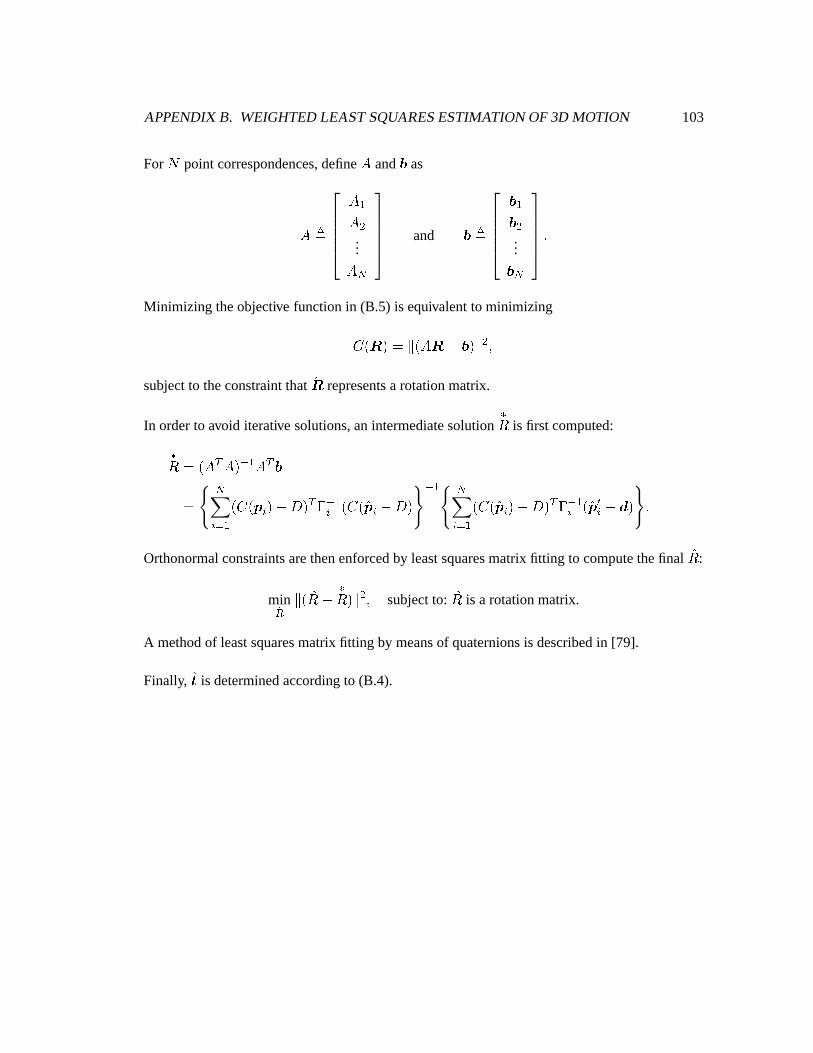
APPENDIXB. WEIGHTEDLEAST SQUARESESTIMATION OF 3D MOTION 103
For Ò point correspondences,define p and r as
p�Ëp Yp d...
p Uand rÇË
r Yr d...
r Uf
Minimizing theobjective functionin (B.5) is equivalentto minimizing
Ó L n S � [ L p�n ^ r S [ed Psubjectto theconstraintthat jn representsa rotationmatrix.
In orderto avoid iterative solutions,anintermediatesolutiontN
is first computed:
tN � L p v p S y Y p v r�UVXWZY L o L j
\ V S�^ q S v ÉMy YV L o L j\ V ^ q Sy Y UVXWZY L o L j
\ V S�^ q S v ÉÔy YV L j\ Æ V ^ s S f
Orthonormalconstraintsarethenenforcedby leastsquaresmatrix fitting to computethefinal jN :
minÕ� [ L jN�^ tN}S [ d P subjectto: jN is a rotationmatrix.
A methodof leastsquaresmatrix fitting by meansof quaternionsis describedin [79].
Finally, jR is determinedaccordingto (B.4).
Bibliography
[1] E. TruccoandA. Verri, IntroductoryTechniquesfor 3-D ComputerVision, PrenticeHall,
1998.
[2] O.Faugeras,ThreeDimensionalComputerVision: A GeometricViewpoint, TheMIT Press,
1993.
[3] S. Z. Li, D. P. Mital, E. K. Teoh,andH. Wang,Eds., RecentDevelopmentsin Computer
Vision.2ndAsianConf. on ComputerVision,ACCV’95. InvitedSessionPapers, Springer-
Verlag,1996.
[4] D. Marr andT. Poggio,“A computationaltheoryof humanstereovision,” Proc.RoyalSoc.
LondonB, 204:301–328,1979.
[5] J. E. W. Mayhew andJ. P. Frisby, “Psychophysicalandcomputationalsutdiestowardsa
theoryof humanstereopsis,” Artificial Intelligence, 17:349–385,1981.
[6] W. E. L. Grimson, “Computationalexperimentswith a featurebasedstereoalgorithm,”
IEEE Trans.PatternAnalysisandMachineVision, 7(1):17–34,1985.
[7] T. S. HuangandA. N. Netravali, “Motion andstructurefrom featurecorrespondences:A
review,” Proc.of theIEEE, 82(2):252–268,1994.
[8] C. P. JerianandR. Jain, “Structurefrom motion— a critical analysisof methods,” IEEE
Trans.Systems,Man,andCybernetics, 21(3):572–588,1991.
[9] J.Weng,T. S.Huang,andN. Ahuja, “Motion andstructurefrom two perspectiveviews: Al-
gorithms,erroranalysis,anderrorestimation,” IEEE Trans.PatternAnalysisandMachine
Vision, 11(5):451–476,1989.
104
BIBLIOGRAPHY 105
[10] N. Navab, R. Deriche,andO. D. Faugeras, “Recovering 3D motion andstructurefrom
stereoand2D tokentrackingcooperation,” Proc. Int. Conf. on ComputerVision, 513–516,
1990.
[11] Y. Q. Shi,C. Q. Shu,andJ.N. Pan, “Unified opticalflow field approachto motionanalysis
from asequenceof stereoimages,” PatternRecognition, 27(12):1577–1590,1994.
[12] G. SteinandA. Shashua,“Direct estimationof motionandextendedscenestructurefor a
moving stereorig,” Proc. IEEE Conf. on ComputerVisionandPatternRecognition, 1998.
[13] P.-K. Ho andR. Chung, “Stereo-motionwith stereoandmotion in complement,” IEEE
Trans.PatternAnalysisandMachineVision, 22(2):215–220,2000.
[14] B. Chebaro,A. Crouzil, L. Massip-Pailhes,andS.Castan,“Fusionof thestereoscopicand
temporalmatchingresultsby analgorithmof coherencecontrolandconflictsmanagement,”
Int. Conf. on ComputerAnalysisof ImagesandPatterns, 486–493,1993.
[15] W.-H. Liao andJ.K. Aggarwal, “Cooperative matchingparadigmfor theanalysisof stereo
imagesequences,” Int. J. of Imaging SystemsandTechnology, 9(3):192–200,1998.
[16] A. Y.-K. Ho andT.-C. Pong, “Cooperative fusionof stereoandmotion,” PatternRecogni-
tion, 29(1):121–130,1996.
[17] J.H. Duncan,L. Li, andW. Wang,“Recoveringthree-dimensionalvelocityandestablishing
stereocorrespondencefrom binocular imageflows,” Optical Engineering, 34(7):2157–
2167,1995.
[18] L. Matthies, “Dynamic stereovision,” Tech.Rep. CMU-CS-89-195,Carnegie Mellon
University, 1989.
[19] M. JenkinandJ. K. Tsotsos,“Applying temporalconstraintsto thedynamicstereoprob-
lem,” ComputerVision,Graphics,andImage Processing, 33(1):16–32,1986.
[20] J.-W. Yi and J.-H. Oh, “Recursive resolvingalgorithm for multiple stereoand motion
matches,” Image andVision Computing, 15(3):181–196,1997.
[21] C. TomasiandT. Kanade, “Shapeandmotion from imagestreamsunderorthography:A
factorizationmethod,” Int. J. of ComputerVision, 9(2):137–154,1992.
BIBLIOGRAPHY 106
[22] I. ShimshoniandR. Basri, “A geometricinterpretationof weak-perspective motion,” IEEE
Trans.PatternAnalysisandMachineVision, 21(3):252–257,1999.
[23] C.J.PoelmanandT. Kanade,“A paraperspective factorizationmethodfor shapeandmotion
recovery,” IEEETrans.PatternAnalysisandMachineVision, 19(3):206–218,1997.
[24] L. KitchenandA. Rosenfeld,“Gray-level cornerdetection,” PatternRecognition Letters,
1:95–102,1982.
[25] F. MokhtarianandR. Suomela, “Robust imagecornerdetectionthroughcurvaturescale
space,” IEEE Trans.PatternAnalysisandMachineVision, 20(12):1376–1381, 1998.
[26] C. TomasiandT. Kanade,“Detectionandtrackingof point features,” Tech.Rep.CMU-CS-
91-132,Carnegie Mellon University, 1991.
[27] B. D. LucasandT. Kanade,“An iterative imageregistrationtechniquewith anapplication
to stereovision,” Proc.7th Int. Joint Conf. onArtificial Intelligence, 674–679,1981.
[28] R. Hartley, “Triangulation,” ComputerVision and Image Understanding, 68(2):146–157,
1997.
[29] Q.T. LuongandO.D. Faugeras,“The fundamentalmatrix: Theory, algorithms,andstability
analysis,” Int. J. of ComputerVision, 17:43–75,1996.
[30] N. Ayacheand B. Faverjon, “Efficient registrationof stereoimagesby matchinggraph
descriptionof edgesegments,” Int. J. of ComputerVision, 1(2):107–131,1987.
[31] S.T. Barnard,“Stochasticstereomatchingoverscale,” Proc.DARPA ImageUnderstanding
Workshop, 769–778,1988.
[32] J. Weng, N. Ahuja, and T. S. Huang, “Matching two perspective views,” IEEE Trans.
PatternAnalysisandMachineVision, 14(8):806–825,1992.
[33] U. R.DhondandJ.K. Aggarwal, “Structurefrom stereo— areview,” IEEETrans.Systems,
Man,andCybernetics, 19(6):1489–1510,1989.
[34] T.-Y. Chen,A. C. Bovik, andL. K. Cormack, “Stereoscopicrangingby matchingimage
modulation,” IEEETrans.Image Processing, 8(6):785–797,1999.
[35] B. J.SuperandW. N. Klarquish,“Patch-basedstereoin ageneralbinocularviewing geom-
etry,” IEEETrans.PatternAnalysisandMachineVision, 19(3):247–253,1997.
BIBLIOGRAPHY 107
[36] T. KanadeandM. Okutomi,“A stereomatchingalgorithmwith anadaptivewindow: Theory
andexperiment,” IEEE Trans.PatternAnalysisandMachineVision, 16(9):920–932,1994.
[37] A. Fusiello,V. Roberto,andE. Trucco, “Efficient stereowith multiple windowing,” Proc.
IEEE Conf. on ComputerVision andPatternRecognition, 858–863,1997.
[38] Z. Zhang,R. Deriche,O. Faugeras,andQ.-T. Luong, “A robusttechniquefor matchingtwo
uncalibratedimagesthroughtherecovery of theunknown epipolargeometry,” Tech.Rep.
2273,INRIA, France,1994.
[39] Y. OhtaandT. Kanade,“Stereoby intra- andinter-scanlinesearch,” IEEE Trans.Pattern
AnalysisandMachineVision, 7(2):139–154,1985.
[40] J. Weng, “Image matchingusing windowed fourier phase,” Int. J. of ComputerVision,
11(3):211–236,1993.
[41] D. J.FleetandA. D. Jepson,“Stability of phaseinformation,” IEEETrans.PatternAnalysis
andMachineVision, 15(12):1253–1268,1993.
[42] M. R. M. JenkinandA. D. Jepson,“Recoveringlocal surfacestructurethroughlocalphase
differencemethods,” ComputerVision, Graphics,and Image Processing:Image Under-
standing, 59(1):72–93,1994.
[43] J.Weng,T. S.Huang,andN. Ahuja, “3-d motionestimation,understanding,andprediction
from noisyimagesequences,” IEEETrans.PatternAnalysisandMachineVision, 9(3):370–
389,1987.
[44] B. K. P. Horn and B. G. Schunck, “Determining optical flow,” Artificial Intelligence,
17:185–203,1981.
[45] H.-H. Nagel, “On theestimationof optical flow: Relationsbetweendifferentapproaches
andsomenew results,” Artificial Intelligence, 33:299–324,1987.
[46] A. Verri andT. Poggio,“Motion field andopticalflow: Qualitativeproperties,” IEEETrans.
PatternAnalysisandMachineVision, 11(5):490–497,1989.
[47] J. K. Aggarwal andN. Nandhakumar, “On thecomputationof motion from sequencesof
images— areview,” Proc.of theIEEE, 76(8):917–935,1988.
BIBLIOGRAPHY 108
[48] H. ShariatandK. E. Price, “Motion estimationwith morethantwo frames,” IEEE Trans.
PatternAnalysisandMachineVision, 12(5):370–389,1990.
[49] J.Philip, “Estimationof three-dimensionalmotionof rigid objectsfromnoisyobservations,”
IEEE Trans.PatternAnalysisandMachineVision, 13(1):61–66,1991.
[50] P. M. Q. Aguiar and J. M. F. Moura, “A fast algorithm for rigid structurefrom image
sequences,” Proc. IEEE Int. Conf. on Image Processing, 125–129,1999.
[51] T. J.BroidaandR. Chellappa,“Kinematicsandstructureof a rigid objectfrom a sequence
of noisyimages,” Proc.Workshopin Motion: RepresentationandAnalysis, 95–100,1986.
[52] G. J. TsengandA. K. Sood, “Analysisof long imagesequencefor structureandmotion
estimation,” IEEE Trans.Systems,Man,andCybernetics, 19(6):1511–1526, 1989.
[53] L. Matthies,T. Kanade,andR. Szeliski, “Kalman filter-basedalgorithmsfor estimating
depthfrom imagesequences,” Int. J. of ComputerVision, 3(3):209–236,1989.
[54] A. AzarbayejaniandA. P. Pentland,“Recursive estimationof motion,structure,andfocal
length,” IEEETrans.PatternAnalysisandMachineVision, 17(6):562–575,1995.
[55] M. S. Grewal andA. P. Andrews, KalmanFiltering: TheoryandPractice, PrenticeHall,
EnglewoodCliffs, New Jersey, 1993.
[56] J.Shi andC. Tomasi,“Good featuresto track,” Proc. IEEE Conf. on ComputerVision and
PatternRecognition, 593–600,1994.
[57] T. Tommasini,A. Fusiello,E. Trucco,andV. Roberto,“Making goodfeaturestrackbetter,”
Proc. IEEE Conf. onComputerVisionandPatternRecognition, 178–183,1998.
[58] I. K. SethiandR. Jain, “Finding trajectoriesof featurepoints in a monocularimagese-
quence,” IEEETrans.PatternAnalysisandMachineVision, 9(1):56–73,1987.
[59] D. Chetverikov andJ.Verestoy, “Trackingfeaturepoints:anew algorithm,” Proc.Int. Conf.
on PatternRecognition, 1436–1438,1998.
[60] Y. Bar-ShalomandT. E. Fortmann,Tracking andData Association, AcadmicPress,1988.
[61] S.D. BlosteinandT. S.Huang,“Detectingsmall,moving objectsin imagesequencesusing
sequentialhypothesistesting,” IEEE Trans.SignalProcessing, 39(7):1611–1629,1991.
BIBLIOGRAPHY 109
[62] I. J. Cox, “A review of statisticaldataassociationtechniquesfor motioncorrespondence,”
Int. J. of ComputerVision, 10(1):53–66,1993.
[63] Z. Zhang,“Tokentrackingin a clutteredscene,” Image andVision Computing, 12(2):110–
120,1994.
[64] I. J. Cox andS. L. Hingorani, “An efficient implementationof Reid’s multiple hypothe-
sis trackingalgorithmandits evaluationfor the purposeof visual tracking,” IEEE Trans.
PatternAnalysisandMachineVision, 18(2):138–150,1996.
[65] L. MatthiesandT. Kanade,“The cycleof uncertaintiesandconstraintin robotperception,”
4th Int. Symposiumon RoboticsResearch, 327–335,1988.
[66] N. AyacheandO.D. Faugeras,“Maintainingrepresentationsof theenvironmentof amobile
robot,” 4th Int. Symposiumon RoboticsResearch, 337–50,1988.
[67] G.-S.J. YoungandR. Chellappa,“3-D motionestimationusingsequenceof noisy stereo
images:Models,estimation,anduniquenessresults,” IEEE Trans.Pattern Analysisand
MachineVision, 12(8):735–759,1990.
[68] C. Q. ShuandY. Q. Shi, “On unifiedopticalflow field,” PatternRecognition, 24(6):579–
586,1990.
[69] J. Pan, Y. Shi, and C. Shu, “A Kalman filter in motion analysisfrom stereoimagese-
quences,” Proc. IEEE Int. Conf. on Image Processing, 3:63–67,1994.
[70] A. M. WaxmanandJ. H. Duncan, “Binocular imageflows: Stepstoward stereo-motion
fusion,” IEEETrans.PatternAnalysisandMachineVision, 8(6):715–729,1986.
[71] J.WangandW. Wilson, “3D relative positionandorientionestimationusingKalmanfilter
for robotcontrol,” Proc. IEEE Conf. on RoboticsandAutomation, 3:2638–2645,1992.
[72] C. Harris, “Tracking with rigid models,” Active Vision, A. Blake and A. Yuille, Eds.,
chapter4. TheMIT Press,1992.
[73] T. S. HuangandS. D. Blostein, “Robust algorithmsfor motion estimationbasedon two
sequentialstereoimagepairs,” Proc.IEEEConf. onComputerVisionandPatternRecogni-
tion, 518–523,1985.
BIBLIOGRAPHY 110
[74] K. S.Arun, T. S.Huang,andS. D. Blostein, “Least-squaresfitting of two 3-D point sets,”
IEEE Trans.PatternAnalysisandMachineVision, 9(5):698–700,1987.
[75] S. Umeyama, “Least-squaresestimationof transformationparametersbetweentwo point
patterns,” IEEE Trans.PatternAnalysisandMachineVision, 13(4):376–380,1991.
[76] S. D. BlosteinandT. S. Huang, “Error analysisin stereodeterminationof 3-D point posi-
tions,” IEEE Trans.PatternAnalysisandMachineVision, 9(6):752–765,1987.
[77] S. ChaudhuriandS. Chatterjee, “Performanceanalysisof total leastsquaresmethodsin
three-dimensionalmotion estimation,” IEEE Trans.Roboticsand Automation, 7(5):707–
714,1991.
[78] D. GorynandS. Hein, “On theestimationof rigid body rotationfrom noisy data,” IEEE
Trans.PatternAnalysisandMachineVision, 17(12):1219–1220, 1995.
[79] J.Weng,T. S.Huang,andN. Ahuja,MotionandStructure fromImageSequences, Springer-
Verlag,1993.
[80] M. A. FischlerandR. C. Bolles, “Randomsampleconsensus:a paradigmfor modelfitting
with applicationsto imageanalysisandautomatedcartography,” Communicationsof the
ACM, 24(6):381–395,1981.