Embed Size (px)
Citation preview

IS 14700 (Part 4/See 3) :2008IEC 6f1000-4-3 :2006
Indian Standard
ELECTROMAGNETIC COMPATIBILITY (EMC)
PART 4 TESTING AND MEASUREMENT TECHNIQUES
Section 3 Radiated, Radio Frequency, Electromagnetic Field Immunity Test
( First Revision)
Ics 33.1 [00.20
@ BIS 2008
BUREAU OF INDIAN STANDARDSMANAK BHAVAN, 9 BAHADUR SHAH ZAFAR MARG
NEW DELHI 110002
September 2008 Price Group 14

II I I - I—J —,—. . . .—..—--- -———— .—.____ -,
Electromagnetic Compatibility Sectional Committee, LITD 09
NATIONAL FOREWORD
This Indian Standard (Part 4/.Sec 3) (First Revision) which is identical with IEC 61000-4-3 : 2006
‘Electromagnetic compatibility (EMC) -— Part 4-3: Testing and measurement techniques — Radiated,radio-frequency, electromagnetic field immunity test’ issued by the international Electrotechnical
Commission (lEC) was adopted by the Bureau (of Indian Standards on the recommendation of the
Electromagnetic Compatibility Sectional Committee and approval of the Electronics and Information
Technology Division Council.
This standard was originally published in 2005 and was identical to IEC 61000-4-3 : 2002. This .standard is being revised to align it with the latest IEC publication IEC 61000-4-3:2006.
The text of IEC Standard has been approved as suitable for publication as an Indian Standard without
deviations. Certain conventions are, however, not identical to those used in Indian Standards. &Attention is particularly drawn to the following:
a) Wherever the words ‘International Standard’ appear referring to this standard, they should
be read as ‘Indian Standard’.
b) Comma (,) has been used as a decimal marker, while in Indian Standards, the current
practice is to use a poirlt (.) as the decimal marker.
In this adopted standard, reference appears to the following International Standard for which Indianstandard a\so exists. The corresponding Indian Standard which is to be substituted in its respective
place is listed below along with its degree of equivalence for the edition indicated:
International Standard Corresponding Indian Standard Degree of
Equivalence
IEC 60050-161 : 1990 International IS 1885 (Parf 85) : 2003 IdenticalElectrotechnical Vocabulary (IEV) — Electrolechnical vocabulary: Part 85Chapter 161: Electromagnetic Electromagnetic compatibilitycompatibility
The technical committee responsible for the preparation of this standard has
of following International Standard referred in this adopted standard and
acceptable for use in conjunction with this standard:
/nternafiona/ Standard Title
reviewed the ~rovisions
has decided that It IS
IEC 61000-4-6:2006 Electromagnetic compatibility (EMC) — Part 4-6: Testing and measurement
techniques — Immunity to conducted disturbances Induced by radio-frequency fields
Orrly the English language text of the International Standard has been retained while adopting it as anIndian Standard, and as such the page numbers given here are not the same as irl the IEC
Publication.6

IS 14700 (Part 4/See 3): 2008IEC 61000-4-3:2006
Indian Standard
ELECTROMAGNETIC COMPATIBILITY (EMC)
PART 4 TESTING AND MEASUREMENT TECHNIQUES
Section 3 Radiated, Radio Frequency, Electromagnetic Field Immunity Test
(First Revision )1 Scope and object
This part of IEC 61000 is applicable to the immunity requirements of electrical and electronicequipment to radiated electromagnetic energy. It establishes test levels and the required testprocedures.
The object of this standard is to establish a common reference for evaluating the immunity ofelectrical and electronic equipment when subjected to radiated, radio-frequency electro-magnetic fields. The test method documented in this part of IEC 61000 describes a consistentmethod to assess the immunity of an equipment or system against a defined phenomenon.
NOTE 1 As described in IEC Guide 107, this is a basic EMC publication for use by product committees of the IEC.As also stated in Guide 107, the lEC product committees are responsible for determining whether this immunitytest standard should be applied or not, and if applied, they are responsible for determining the appropriate testlevels and performance criteria. TC 77 and its sub-committees are prapared to co-operate with product committeesin the evaluation of the value of particular immunity tests for their products,
This part deals with immunity tests related to the protection against RF electromagnetic fieldsfrom any source.
Particular considerations are devoted to the protection against radio-frequency emissionsfrom digital radiotelephones and other RF emitting devices.
NOTE 2 Test methods are defined in this part for evaluating the effect that electromagnetic radiation has on theequipment concerned. The simulation and measurement of electromagnetic radiation is not adequately exact forquantitative determination of effects. The test methods defined are structured for the primary objective ofestablishing adequate repeatability of results at various test facilities for qualitative analysis of effects,
This standard is an independent test method. Other test methods may not be used a.ssubstitutes for claiming compliance with this standard.
2 Normative references
The following referenced documents are indispensable for the application of this document.For dated references, only the edition cited applies. For undated references, the latest editionof the referenced document (including any amendments) applies.
IEC 60050(161), International Electrotechnical Vocabulary (IEV) – Chapter 161: Electro-magnetic compatibility
IEC 61000-4-6, Electromagnetic compatibility (EMC) – Part 4-6,” Testing and measurementtechniques – Immunity to conducted disturbances, induced by radio-frequency fields

1111 1111 1. .w.——— —-——... . .. .. . . . . ,,. . .. ..-—. —.— . -. —,
IS 14700 (Part 4/See 3) :2008
IEC 61000-4-3:2006
3 Terms and definitions
For the purposes of this part of IEC 61000, the following definitions, together with those inIEC 60050(161) apply.
3.1amplitude modulationprocess by which the amplitude of a carrier wave is varied following a specified law
3.2anechoic chambershielded enclosure which is lined with radio-frequency absorbers to reduce reflections fromthe internal surfaces
3.2.1fully anechoic chambershielded enclosure whose internal surfaces are totally lined with anechoic material
3.2.2semi-anechoic chambershielded enclosure where all internal surfaces are covered with anechoic material with theexception of the floor, which shall be reflective (ground plane)
3.2.3modified semi -anechoic chambersemi-a nechoic chamber which has additional absorbers installed on the ground plane
3.3antennatransducer which either emits radio-frequency power into space from a signal source orintercepts an arriving electromagnetic field, converting it into an electrical signal
3.4balundevice for transforming an unbalanced voltage to a balanced voltage or vice versa
[IEV 161-04-34]
3.5continuous waves (CW)electromagnetic waves, the successive oscillations of which are identical under steady-stateconditions, which can be interrupted or modulated to convey information
3.6electromagnetic (EM) waveradiant energy produced by thethe electric and magnetic fields
3.7far field
oscillation of an electric charge characterized by oscillation of
region where the power flux density from an antenna approximately obeys an inverse squarelaw of the distance.
For a dipole this corresponds to distances greater than 2/27c, where 2 is the wavelength of theradiation
2

IS 14700 (Part 4/See 3) :2008IEC 61000-4-3:2006
3.8field strengthThe term “field strength” is applied only to measurements made in the far field. Themeasurement may be of either the electric or the magnetic component of the field and may beexpressed as V/m, A/m or W/m2; any one of these may be converted into the others.
NOTE For measurements made in the near field, the term “electric field strength” or “magnetic field strength” isused according to whether the resultant electric or magnetic field, respectively, is measured. In this field region,the relationship between the electric and magnetic field strength and distance is complex and difficult to predict,being dependent on the specific configuration involved. Inasmuch as it is not generally feasible to determine thetime and space phase relationship of the various components of the complex field, the power flux density of thefield is similarly indeterminate.
3.9frequency bandcontinuous range of frequencies extending between two limits
3.10Ecfield strength applied for calibration
3.11E,carrier field strength applied for testing
3.12full illuminationtest method in which the EUT face being tested fits completely within the UFA (Uniform FieldArea).
This test method may be applied for all test frequencies
3.13human body-mounted equipmentequipment which is intended for use when attached to or held in close proximity to the humanbody.
This term includes hand-held devices which are carried by people while in operation (e.g.pocket devices) as well as electronic aid devices and implants
3.14independent windows methodtest method (using 0,5 m x 0,5 m UFA) in which the EUT face being tested does not fitcompletely within the UFA,
This test method may be applied for test frequencies greater than 1 GHz
3.15induction field
predominant electric and/or magnetic field existing at a distance d < 2/2x, where 2 is thewavelength, and the physical dimensions of the source are much smaller than distance d
3.16intentional RF emitting devicedevice which radiates (transmits) an electromagnetic field intentionally. Examples includedigital mobile telephones and other radio devices
3

..—...-
1S 14700 (Part 4/See 3) :2008
IEC 61000-4-3:2006
3.17isotropichaving properties of equal values in all directions
3.18maximum RMS valuehighest short-term RMS value of a modulated RF signal during an observation time of one
modulation period.
The short-term RMS is evaluated over a single carrier cycle. For example, in Figure lb), themaximum RMS voltage is:
Vmaximum RMS = Vp-p I (2 x a ) = 1,8 V
3.19non-constant envelope modulationRF modulation schemes in which the amplitude of the carrier wave varies slowly in timecompared with the period of the carrier itself. Examples include conventional amplitudemodulation and TDMA
3.20Pcforward power needed to establish the calibration field strength
3.21partial illuminationtest method (using a minimum sized UFA of 1,5 x 1,5 m) in which the EUT face being testeddoes not fit completely within the UFA.
This test method may be applied for all test frequencies.
3.22polarizationorientation of the electric field vector of a radiated field
3.23shielded enclosurescreened or solid metal housing designed expressly for the purpose of isolating the internalfrom the external electromagnetic environment. The purpose is to prevent outside ambientelectromagnetic fields from causing performance degradation and to prevent emission fromcausing interference to outside activities
3.24sweepcontinuous or incremental traverse over a range of frequencies
3.25TDMA (time division multiple access)time multiplexing modulation scheme which places several communication channels on thesame carrier wave at an allocated frequency. Each channel is assigned a time slot duringwhich, if the channel is active, the information is transmitted as a pulse of RF power. If thechannel is not active no pulse is transmitted, thus the carrier envelope is not constant. Duringthe pulse, the amplitude is constant and the RF carrier is frequency- or phase-modulated

IS 14700 (Part 4/See 3) :2008
IEC 61000-4-3:2006
3.26transceivercombination of radio transmitting and receiving equipment in a common housing
3.27uniform field area (UFA)hypothetical vertical plane of the field calibration in which variations are acceptably small
The purpose of field calibration is to ensure the validity of the test result. See 6,2
4 General
Most electronic equipment is, in some manner, affected by electromagnetic radiation. Thisradiation is frequently generated by such general purpose sources as the small hand-heldradio transceivers that are used by operating, maintenance and security personnel, fixed-station radio and television transmitters, vehicle radio transmitters, and various industrialelectromagnetic sources.
In recent years there has been a significant increase in the use of radio telephones and otherRF emitting devices operating at frequencies between 0,8 GHz and 6 GHz. Many of theseservices use modulation techniques with a non-constant envelope (e.g. TDMA). See 5.2.
In addition to electromagnetic energy deliberately generated, there is also radiation caused bydevices such as welders, thyristors, fluorescent lights, switches operating inductive loads, etc.For the most part, this interference manifests itself as conducted electrical interference and,as such, is dealt with in other parts of the IEC 61000-4 standard series. Methods employed toprevent effects from electromagnetic fields will normally also reduce the effects from thesesources.
The electromagnetic environment is determined by the strength of the electromagnetic field.The field strength is not easily measured without sophisticated instrumentation nor is it easilycalculated by classical equations and formulas because of the effect of surrounding structuresor the proximity of other equipment that will distort and/or reflect the electromagnetic waves.
5 Test levels
The test levels are given in Tab!e 1.
Table 1- Test levels related to general purpose, digitaland other RF emitting devices
radio telephones
!
Level Test field strength
V/m
1 1
2 3
3 10
4 30
x Special
NOTE x is an open test level and the associated field strength maybe any value. This level may be given in the product standard.
!5

1S 14700 (Part 4/See 3) :2008
IEC 61000-4-3:2006
This standard does not suggest that a single tesit level is applicable over the entire frequencyrange. Product committees shall select the appropriate test level for each frequency rangeneed~ng to be tested as well as the frequency ranges. See Annex E for a guidance for productcommittees on the selection of test levels.
The !est field strength column gives values of the unmodulated carrier signal. For testing ofequipment, this carrier signal is 80’10 amplitude modulated with a 1 kHz sine wave to simulate
‘actual threats (see Figure 1 ), Details of how the test is performed are given in Clause 8.
5.1 Test levels related to general purposes
The tests are normally performed without gaps in the frequency range 80 MHz to 1000 MHz.
NOTE; 1 Product committees may decide to choose a lower of higher transition frequency than 80 MHz betweenIEC 61000-4-3 and IEC 61000-4-6 (see Annex G).
NOTE 2 Product committees may select ‘alternative modulation schemes for equipmant under test.
NOTE 3 IEC 61000-4-6 also defines test methods for establishing the immunity of electrical and electronicequipment against radiated electromagnetic energy. It covers frequencies below 80 MHz.
5.2 Test levels related to the protection against RF emissions from digital radiotelephones and other RF emitting devices
The tests are normally pr3rfOrmr?d in the frequency ranges 800 MHz to 960 MHz and 1,4 GHzto 6,0 GHz.
The frequencies or frequency bands to be selected for the test are limited to those wheremobile radio telephones and ott?er intentional RF emitting devices actually operate. It is not\ntended that the test needs to be applied continuously over the entire frequency range from1,4 GHz to 6 GHz. For those frequency bands used by mobile radio telephones and otherIntentional RF emitting devices, specific test levels may be applied in the correspondingflequency range of operation.
A!SO If the product is intended to conform only to the requirements of particular countries, themeasurement range 1,4 GHz to 6 GH.z may be reduced to cover just the specific frequencybands allocated to digital mobile telephones a~d other intentional RF emitting devices inthose countries. In this situation, the decismn to “test over reduced frequency ranges shall bedocumented in the test repOrt.
NCJTE 1 Annex A contains an explanation regarding the decismn to use sine wave modulation for tests related toplotecilon against RF emissions from digital radio telephones and other intentional RF emitting devices.
N(>TE 2 Annex E ~or-ltains guidance with regard to ?dedln~ k!sk kVdS.
NOTE 3 The measurement ranges for Table 2 are the frequency bands generally allocated to digital radiotelephones (Annex G contains the list of frequencies knwvn to be allocated to specific digital radio telephones etthe t{me of publication).
NOTE 4 The primary threat above 800 MHz is from mdio telephone systems and other intentional RF emittingdevices with power levels similar to that of radio telephones. Other systems operating in this frequency range, e.g.radio LANs operating at 2,4 GHz or higher frequencies, are generally very low power (typically lower than100 mW), so they are much less likely to present significant problems.
6

IS 14700 (Part 4/See 3): 2008IEC 61000-4-3:2006
6 Test equipment
The following types of test equipment are recommended:
– Anechoic chamber.’ of a size adequate to maintain a uniform field of sufficient dimensionswith respect to the equipment under test (EUT). Additional absorbers may be used todamp reflections in chambers which are not fully lined.
EMl fi/fers: care shall be taken to ensure that the filters introduce no additional resonanceeffects on the connected lines.
RF signs/ generator(s) capabie of covering the frequency band of interest and of beingamplitude modulated by a 1 kHz sine wave with a modulation depth of 80Y0. They shallhave manual control (e. g., frequency, amplitude, modulation index) or, in the case of RFsynthesizers, they shall be programmable with frequency-dependent step sizes and dwelltimes.
The use of low-pass or band-pass filters may be necessary to avoid problems caused byharmonics,
— Power amplifiers: to amplify signal (unmodulated and modulated) and provide antennadrive to the necessary field level. The harmonics generated by the power amplifier shall besuch that any measured field strength in the UFA at each harmonic frequency shall be atleast 6 dB below that of the fundamental frequency (see Annex D).
– Field generating antennas (see Annex B): biconical, log periodic, horn or any other linearlypolarized antenna system capable of satisfying frequency requirements.
— An isotropic field sensor with adequate immunity of any head amplifier and opto-electronics to the field strength to be measured, and a fibre optic link to the indicatoroutside the chamber. An adequately filtered signal link may also be used.
– Associated equipment to record the power levels necessary for the required field strengthand to control the generation of that level for testing.
Care shall be taken to ensure adequate immunity of the auxiliary equipment
6.1 Description of the test facility
Because of the magnitude of the field strengths generated, the tests shall be made in ashielded enclosure in order to comply with various national and international laws prohibitinginterference to radio communications. In addition, since most test equipment used to collectdata is sensitive to the local ambient electromagnetic field generated during the execution ofthe immunity test, the shielded enclosure provides the necessary “barrier” between the EUTand the required test instrumentation. Care shall be taken to ensure that the interconnectionwiring penetrating the shielded enclosure adequately attenuates the conducted and radiatedemission and preserves the integrity of the EUT signal and power responses.
The test facility typically consists of an absorber-lined shielded enclosure large enough toaccommodate the EUT whilst allowing adequate control over the field strengths. This includesanechoic chambers or modified semi-a nechoic chambers, an example of which is shown inFigure 2, Associated shielded enclosures should accommodate the field generating andmonitoring equipment, and the equipment which exercises the EUT.
Anechoic chambers are less effective at lower frequencies. Particular care shall be taken toensure the uniformity of the generated field at the lower frequencies. Further guidance isgiven in Annex C.
7

IS 14700 (Part 4/See 3) :2008IEC 61000-4-3:2006
6.2 Calibration of field
The purpose of field calibration is to ensure that the uniformity of the field over the testsample is sufficient to ensure the validity of the test results. IEC 61000-4-3 uses the conceptof a uniform field area (UFA, see Figure 3), which is a hypothetical vertical plane of the fieldin which variations are acceptably small. In a common procedure (field calibration), thecapability of the test facility and the test equipment to generate such a field is demonstrated.At the same time, a database for setting the required field strength for the immunity test isobtained. The field calibration is valid for all EUTS whose individual faces (including anycabling) can be fully covered by the UFA.
The field calibration is performed with no EUT in place (see Figure 3). In this procedure, therelationship between field strength within the UFA and forward power applied to the antennais determined. During the test, the required forward power is calculated from this relationshipand the target field strength. The calibration is valid as long as the test setup used for itremains unchanged for testing, therefore the calibration setup (antenna, additional absorber,cables, etc. ) shall be recorded. It is important that the exact position, as much as isreasonably possible, of the generating antennas and cables is documented, Since even smalldisplacements may significantly affect the field, the same positions shall be used also for theImmunity test.
!t is intended that the full field calibration process should be carried out annually and whenchanges have been made in the enclosure configuration (absorber replaced, area moved,equipment changed, etc.). Before each batch of testing (see Clause 8), the validity of thecalibration shall be checked.
The transmitting antenna shall be placed at a distance sufficient to aliow the UFA to fall withinthe beam of the transmitted field. The field sensor shall be at least _l m from the fieldgenerating antenna. A distance of 3 m between the antenna and the UFA is preferred (seeFigure 3). This dimension is measured from the centre of a biconical antenna, or the front tipof a log periodic or combination antenna, or from! the front edge of horn or double ridge waveguide antenna. The calibration record and the test report shall state the distance used.
~Jniess the EUT and its wires can be fully illuminated within a smaller surface, the size of theUFA IS at least 1,5 m x 1,5 m with its lower edge established at a height of 0,8 m above thefloor The size of the UFA shall not be !ess than G,5 m x 0,5 m. During the immunity test, theEUT shall have the face to be illuminated coincident with this UFA (see Figures 5 and 6).
In order to establish the severity of the test fcr EUTS and cabling which must be tested closeto the floor (earth reference plane), the magnitude of the field is also recorded at 0,4 mheight. The obtained data is documented in the calibration record but is not considered for thesuitability of the test facility and for the calibration database,
Due to reflections at the floor in a semi-an echoic room, it is difficult to establish a UFA closeto an earth reference plane. Additional absorbing material on the earth reference plane maysolve this problem (see Figure 2).
The UFA is subdivided into a grid with a grid spacing of 0,5 m (see Figure 4 as an example ofan 1,5 m x 1,5 m UFA). At each frequency, a field is considered uniform if its magnitude
measured at the grid points is within ~6dB of the nominal value for not less than 75 YO of all
grid points (e g, if at least 12 of the 16 points of an 1,5 m x 1,5 m UFA measured are withinthe tolerance). For the minimum UFA of 0,5 m x 0,5 m, the field magnitude for all four gridpoints shall lie within this tolerance.
8

IS 14700 (Part 4/See 3) :2008
IEC 61000-4-3:2006
NOTE 1 At different frequencies, different measuring points may be within the tolerance.
The tolerance has been expressed as ~dB to ensure that the field strength does not fall
beIOW nominal with an acceptable probability. The tolerance of 6 dB is considered to be the
minimum achievable in practical test facilities,
In the frequency range up to 1 GHz, a tolerance greater than +6 dB, up to +10 dB, but notless than -O dB is allowed for a maximum of 3 % of the test frequencies, provided that the
actual tolerance is stated in the test report. In case of dispute, the ~~dB tolerance takes
precedence.
If the area intended to be occupied by the face of the actual EUT is larger than 1,5 m x 1,5 mand an UFA with sufficient dimensions (preferred method) can not be realised, then the areato be occupied by the EUT may be illuminated in a series of tests (“partial illumination”).Either:
— a calibration shall be performed at different radiating antenna locations so that thecombined UFAS cover the area which will be occupied by the face of the EUT, and theEUT shall then be tested with the antenna in each of these positions successively,
— or the EUT shall be moved to different positions so that each part of it falls within the UFAduring at least one of these tests.
NOTE 2 Each of the antenna positions requires a full field calibration.
Table 2 below demonstrates the concepts of full illumination and partial illumination as well aswhere and how they can be applied.
Table 2- Requirements for uniform field area for application of full illumination, partialillumination and independent windows method
‘requency range Requirements of UFA size and Requirements of UFA size and calibrationcalibration when the EUT fits when the EUT does not fit completelycompletely within UFA (Full within UFA (Partial Illumination and
Illumination, the preferred method) Independent Windows, the alternativemethods)
.ess than 1 GHz Minimum UFA size 0,5 m x 0,5 m PARTIAL ILLUMINATION
UFA size in 0,5 m grid size steps (e.g., Minimum UFA size 1,5 m x 1,5 m0,5mx0,5m; 0,5mxl,0m; l,0m x1,0 m; etc)
UFA size ~n 0,5 m grid size steps (e.g.,
l,5mxl,5m; l,5mx2,0m;2,0m x2,0m;Calibration in 0,5 m x 0,5 m grid steps etc)
75 ‘A of calibration points within Calibration in 0,5 m x 0,5 m grid stepsspecifications if UFA is larger than0,5 m x 0,5 m. 100 % (all 4 points) mustbe in specifications for 0,5 m x 0,5 m 75 % of calibration pointa within
UFA. specifications
9

. .
IS 14700 (Part 4/See 3) :2008
IEC 61000-4-3:2006
Table 2 (continued)
Frequency range Requirements of UFA size and Requirements of UFA size and calibrationcalibration when the EUT fits when the EUT does not fit completelycompletely within UFA (Full within UFA (Partial Illumination and
Illumination, the preferred method) Independent Windows, the alternativemethods)
Greater than 1 GHz Minimum UFA size 0,5 m x 0,5 m INDEPENDENTWINDOWS METHOD
UFA size in o,5 m grid size staps (e.g., 0,5 m x 0,5 m window (See Annex H)0,5mx0,5fn; 0,5mxl,0m;l, Omxl,Om; etc) PARTIAL ILLUMINATION
Calibration In 0,5 m x 0,5 m grid staps 1,5 m x 1,5 m and Iargar size windowe in0,5 m increments (e.g., 1,5 m x 2,0 m;
75 % of calibration points within 2,0 m x 2,0 m; etc)specifications if UFA is larger than 0,5 mx 0,5 m. 100 % (all 4 points) must be inspecifications for 0,5 m x 0,5 m UFA.
Calibration in 0,5 m x 0,5 m grid steps
75 % of calibration points withinspecifications if UFA is larger than0,5 m x 0,5 m. 100 % (all 4 points) must be inspecifications for 0,5 m x 0,5 m UFA.
If the requirements of this subclause can only be satisfied UP to a certain Iimitinc! frequencv(higher than 1 GHz), for example because the beam width of the antenna is in&uTic~ent t;illuminate the entire EUT, then for frequencies higher than this, a second alternative method(known as “the independent window method”), described in Annex H, may be used.
Generally the calibration of the field in anechoic and semi-anechoic chambers has to beperformed using the test setup shown in Figure 7. The calibration shall always be performedwith an unmodulated carrier for both horizontal and vertical polarisations in accordance withthe steps given below. It is required to ensure that the amplifiers can handle the modulationand are not saturated during testing. The preferred method to ensure the amplifiers are notsaturated during testing is to carry out the calibration with a field strength at least 1,8 times ashigh as the field strength to be applied to the EUT. Denote this calibration field strength by EC,Ec is the value which is applicable only to field calibration. The test field strength Et shall notexceed Ec 1~,8.
NOTE 3 Other methods to ansure avoiding saturation may be used.
Two different calibration methods are described below using an 1,5 m x 1,5 m UFA (16 gridpoints) as an example. These methods are considered to give the same field uniformity.
6.2.1 Constant field strength calibration method
The constant field strength of the uniform field shall be established and measured via acalibrated field sensor at each particular frequency and at each of the 16 points one after theother (see Figure 4) using the step size given in Clause 8, by adjusting the forward poweraccordingly.
The forward power necessary to establish the field strength chosen shall be measured inaccordance with Figure 7 and is to be recorded in dBm for the 16 points.
10

IS 14700 (Part 4/See 3) :2008
IEC 61000-4-3:2006
Procedure to be followed at both horizontal and vertical polarisations:
a) Position the sensor at one of the 16 points in the grid (see Figure 4), and set thefrequency of the signal generator output to the lowest frequency in the range of the test
(for example 80 MHz).
b) Adjust the forward power to the field-generating antenna so that the field strength obtainedis equal to the required calibration field strength EC. Record the forward power reading.
c) Increase the frequency by a maximum of 1 YO of the present frequency
d) Repeat steps b) and c) until the next frequency in the sequence would exceed the highestfrequency in the range of the test. Finally, repeat step b) at this highest frequency (forexample 1 GHz).
e) Repeat steps a) to d) for each point in the grid.
At each frequency:
f) Sort the 16 forward power readings into ascending order.
g) Start at the highest value and check if at least the 11 readings below this value are withinthe tolerance of –6 dB to +0 dB of that value.
h) If they are not within this tolerance of –6 dB to +0 dB, go back to the same procedure,starting by the reading immediately below and so on (notice that there are only fivepossibilities for each frequency).
i) Stop the procedure if at least 12 numbers are within 6 dB and record the maximumforward power out of the numbers. Denote this forward power by PC.
j) Confirm that the test system (e.g. the power amplifier) is not in saturation. Assuming thatEC has been Choseil as 1,8 times Et, perform the following procedure at each calibrationfrequency:
j-1) Decrease the output from the signal generator by 5,1 dB from the level needed toestablish a forward power of PO, as determined in the above steps. (-5,1 dB is thesame as EC /1,8.);
j-2) Record the new forward power delivered to the antenna;
j-3) Subtract the forward power measured in step j-2 from PC. If the difference isbetween 3,1 and 5,1 dB, then the amplifier is not saturated and the test systemsufficient for testing. If the difference is less than 3,1 dB, then the amplifier issaturated and is not suitable for testing.
NOTE 1 if at a specific frequency, the ratio between Ec and Et is R(dB), where R = 20 log(E#Et), then the testpower Pt = Pc - R(dB). The subscripts c and t refer to calibration and test respectively. The field is modulated inaccordance with Clause 8.
A description of an example for the calibration is given in D.4,1.
NOTE 2 At each frequency it has to be ensured that the amplifier used is not saturated. This can best be done bychecking the 1 dB compression of the amplifier. However, the 1 dB compression of the amplifier is verified with a50 n termination when the impedance of an antenna to be used for the test is different from 50 ~. The saturation ofthe test system is assured by confirming the 2 dB compression point dascribed to step j). For more informationrefer to the Annex D.
6.2.2 Constant power calibration method
The field strength of the uniform field shall be established and measured via a calibrated fieldsensor at each particular frequency and at each of the 16 points one after the other (seeFigure 4) using the step size given in Clause 8, by adjusting the forward power accordingly.
11

IS 14700 (Part 4/See 3) :2008
lEC 61000-4-3:2006
The forward power necessary to establish the field strength at the starting position shall bemeasured in accordance with Figure 7 and noted. The same forward power shall be appliedfor all 16 positions. The field strength created by this forward power is to be recorded at eachof the 16 points.
Procedure to be followed at both horizontal and vertical polarisations:
a) Position the sensor at one of the 16 points in the grid (see Figure 4), and set thefrequency of the signal generator output to the lowest frequency in the range of the test(for example 80 MHz).
b) Apply a forward power to the field-generating antenna so that the field strength obtainedequals EC (taking into account that the test field will be modulated). Record the forwardpower and field strength readings.
c) Increase the frequency by a maximum of 170 of the present frequency.
d) Repeat steps b) and c) until the next frequency in the sequence would exceed the highestfrequency in the range of the test. Finally, repeat step b) at this highest frequency (forexample 1 GHz),
e) Move the sensor to another position in the grid. At each of the frequencies and used insteps a) to d), apply the forward power recorded in step b) for that frequency, and recordthe field strength reading.
f) Repeat step e) for each point in the grid
At each frequency
g) Sort the 16 field strength readings into ascending order
h) Select one field strength as the reference and calculate the deviation from this referencefor all other positions in decibels.
i) Start at the lowest value of the field strength and check if at least 11 readings above’this
value are within the tolerance of ~dB of that lowest value.
J) If they are not within the tolerance of ~6dB, go back to the same procedure, starting by
the reading immediately above and so on (notice that there are only five possibilities foreach frequency).
k) Stop the procedure if at least 12 numbers are within 6 dB and take from these numbersthe position where the minimum field strength was obtained as the reference.
1) Calculate the forward power necessary to create the required field strength in thereference position. Denote this forward power by f’c.
m) Confirm that the test system (e. g. the power amplifier) is not in saturation. Assuming thatEC has been chosen as 1,8 times Et, perform the following procedure at each calibrationfrequency:
m-l ) Decrease the output from the signal gensrator by 5,1 dB from the level needed toestablish a forward power of PC, as determined in the above steps. (-5,1 dB is thesame as EC /1,8. )
m-2) Record the new forward power delivered to the antenna
m-3) Subtract the forward power measured in step m-2 from PC. If the difference isbetween 3,1 dB and 5,1 dB, then the amplifier is not saturated and the test systemis sufficient for testing. If the difference is less than 3,1 dB, then the amplifier issaturated and is not suitable for testing.
NOTE 1 If at a specific frequency, the ratio between .EC and Et is /?(dB), where R = 20 log(E#EJ, then the testpower Pt = Pc - R(dB). The subscripts c and t refer to calibration and test respectively. The field is modulated inaccordance with Clause 8.
12

IS 14700 (Part 4/See 3): 2008
IEC 61000-4-3:2006
A description of an example for the calibration is given In D.4.2,
NOTE 2 At each frequency it has to be ensured that the amplifier used is not saturated, This can best be done bychecking the 1 ctB compression of the amplifier. However, the 1 dB compression of the amplifier is verified with a500 termination when the impedance of an antenna to be used fOr the test is different from 5(I n, The saturation ofthe test system is assured by confirming the 2 dB compression point described to step m). For more informationrefer to the Annex D.
7 Test setup
All testing of equipment shall be performed in a configuration as close as possible to actualinstallation conditions. Wiring shall be consistent with the manufacturer’s recommendedprocedures, and the equipment shall be in its housing with all covers and access panels inplace, unless otherwise stated,
If the equipment is designed to be mounted in a panel, rack or cabinet, it shall be tested inthis configuration.
A metallic ground plane is not required. When a means is required to support the test sample,it shall be constructed of a non-metallic, non-conductive material. Low dielectric constant (lowpertmittivity) materials, such as rigid polystyrene, should be considered. However, groundingof housing or case of the equipment shall be consistent with the manufacturer’s installationrecommendations.
When an EUT consists of floor-standing and table-top components, the correct relativepositions shall be maintained.
Typical EUT setups are shown in Figures 5 and 6,
NOTE 1 Non-conductive supports are used to prevent accidental earthing of the EUT and distortion of the field.To ensure the latter, the support should be bulk non-conductive, rather than an insulating coating on a r,letallicstructure.
NOTE 2 At-higher frequencies (e.g., above 1 GHzI, tables or supports made from wood or glass reinforced plasticcan be reflective. So, a low dielectric constant (low permittivity) material, such as rigid polystyrene, should be usedto avoid field perturbations and to reduce degradation of field uniformity.
7.1 Arrangement of table-top equipment
The equipment to be tested is placed in the test facility on a non-conductive table 0,8 m high.
The equipment is then connected to power and signal wires according to relevant installationinstructions.
7.2 Arrangement of floor-standing equipment
Floor-standing equipment should be mounted on a non-conductive support 0,05 m to 0,15 mabove the supporting plane. The use of non-conductive supports prevents accidental earthingof the EUT and distortion of the field. To ensure the iatter, the support shall be bulk non-conducting, rather than an insulating coating on a metallic structure. Floor-standingequipment which is capable of being stood on a non-conductive 0,8 m high platform, i.e.equipment which is not too large or heavy, or where its elevation would not create a safetyhazard, may be so arranged. This variation In the standard method of test shall be recorded inthe test report.
NOTE Non-conductive rollers may be used as the 0,05 m to 0,15 m support
The equipment is then connected to power and signal wires according to relevant installationinstructions.
13

IS 14700 (Part 4/See 3) :2008
IEC 61000-4-3:2006
7.3 Arrangement of wiring
Cables shall be attached to the EUT and arranged on the test site according to themanufacturer’s installation instructions and shall replicate typical installations and use asmuch as possible.
The manufacturer’s specified wiring types and connectors shall be used. If the wiring to andfrom the EUT is not specified, unshielded parallel conductors shall be used.
If the manufacturer’s specification requires a wiring length of less than or equal to 3 m, thenthe specified length shall be used. If the length specified is greater than 3 m or is notspecified, then the length of cable used shall be chosen according to typical installationpractices, If possible, a minimum of 1 m of cable is exposed to the electromagnetic field.Excess length of cables interconnecting units of the EUT shall be bundled low-inductively inthe approximate center of the cable to form a bundle 30 cm to 40 cm in length.
If a product committee determines excess cable length needs to be decoupled (for example,for cables leaving the test area), then the decoupling method used shall not impair theoperation of the EUT.
7.4 Arrangement of human body-mounted equipment
Human body-mounted equipment (see Definition 3.13) may be tested in the same manner astable top items, However, this may involve over-testing or under-testing because the
characteristics of the human body are not taken into account. For this reason, productcommittees are encouraged to specify the use of a human body simulator with appropriatedielectric characteristics.
8 Test procedure
The test procedure includes:
— the verification of the laboratory reference conditions;
— the preliminary verification of the correct operation of the equipment;
the execution of the test;
the evaluation of the test results.
8.1 Laboratory reference conditions
In order to minimize the effect of environmental parameters on test results, the test shall becarried out in climatic and electromagnetic reference conditions as specified in 8.1.1 and8.1.2.
8.1.1 Climatic conditions
Unless otherwise specified by the committee responsible for the generic or product standard,the climatic conditions in the laboratory shall be within any limits specified for the operation ofthe EUT and the test equipment by their respective manufacturers.
Tests shall not be performed if the relative humidity is so high as to cause condensation onthe EUT or the test equipment.
NOTE Where it is considered that there is sufficient evidence to demonstrate that the effects of the phenomenoncovered by this standard ere influenced by climatic conditions, this should be brought to the attention of thecommittee responsible for this standard.
14

IS 14700 (Part 4/See 3): 2008IEC 61000-4-3:2006
8.1.2 Electromagnetic conditions
The electromagnetic conditions of the laboratory shall be such to guarantee the correctoperation of the EUT in order not to influence the test results.
8.2 Execution of the test
The test shall be carried out on the basis of a test plan that shall include the verification of theperformances of the EUT as defined in the technical specification.
The EUT shall be tested in normal operating conditions.
The test plan shall specify:
– the size of the EUT;
– representative operating conditions of the EUT;
– whether the EUT shall be tested as table-top or floor-standing, or a combination of thetwo;
– for floor-standing equipment, the height of the support;
– the type of test facility to be used and the position of the radiating antennas;
– the type of antennas to be used;
- the frequency range, dwell time and frequency steps;
– the size and shape of the uniform field area;
- whether any partial illumination is used;
– the test level to be applied;
– the type(s) and number of interconnecting wires used and the interface port (of the EUT)to which these are to be connected;
– the performance criteria which are acceptable;
- a description of the method used to exercise the EUT.
The test procedures described in this clause are for the use of field generating antennas asdefined in Clause 6.
Before testing the intensity of the calibrated field strength should be checked to verify that thetest equipmentlsystem is operating properly.
After the calibration has been verified, the test field can be generated using the valuesobtained from the calibration (see 6.2).
The EUT is initially placed with one face coincident with the calibration plane. The EUT facebeing illuminated shall be contained within the UFA unless partial illumination is beingapplied. See Clause 6.2 regarding field calibration and use of patital illumination.
The frequency ranges to be considered are swept with the signal modulated according to 5.1and 5.2, pausing to adjust the RF signai level or to switch oscillators and antennas as necessary.Where the frequency range is swept incrementally, the step size shall not exceed 1 % of thepreceding frequency value.
The dwell time of the amplitude modulated carrier at each frequency shall not be less than thetime necessary for the EUT to be exert-ked and to respond, but shall in no case be less than0,5 s. The sensitive frequencies (e.g., clock frequencies) shall be analyzed separatelyaccording to the requirements in product standards.
15

IS 14700 (Part 4/See 3) :2008
IEC 61000-4-3:2006
The test shall r?ormally be performed with the generating antenna facing each side of theEUT ‘When equipment Cai) be used In different orientations (i. e vertical or horizontal) allsides shall be exposed to the field during the teSL VVl?en technically justified, some EUTS cafibe iested by exposing fewer faces to the generating antenna. In other cases, as determinedfor example by the type and size of EL!T or the freq!~encies of test, more than four azimuthsmzy need to be exposed.
NOTE 1 AS the electrical size of the EUT increases, the complexity of its antenna pattern also increases. Thea,nt~nnapattern complexity can affect the number cf test orientations necessary to determine minimuin irrlmunity.
NOTE 2 If an EUT consists of several components, it is not necessary to modify the position of each componentwith’n the EUT while illuminating it from diffefent sides.
The polarization of the field generated by each antenna necessitates testing each selectedside twice, once with the antenna pc&itioned vertically and again with the antenna positionedhorizontally.
Attempts shall be made to fully exercise the EUT during testing, and to interrogate ali thecrftca! exercise modes selected for the immunity test. The use of special exercisingprogrammed is recommended
9 Evaluation of test results
The test results shall be classified in terms of the loss of function or degradation ofperformance of the equipment under test, relative to a performance level defined by its manu-facturer or the requestor of the test, or agreed between the manufacturer and the purchaser ofthe product. The recommended classification is as follows:
a) rlormal performance within limits specified by the manufacturer, requestor or purchaser;
b;) temporary loss of function or degradation of performance which ceases after thedisturbance ceases, and from which the equipment under test recovers its normalperformance, without operator intervention;
c) temporary loss of function or degradation of performance, the correction of which requiresoperator intervention;
d) loss of function or degradation of rjerformance which is not recoverable, owing to damageto hardware or software, or !OSS of data
The manufacturer’s specification may define effects on the EUT which may be consideredInslgnlflcant, and therefore acceptable.
T171s classification may be used as a guide in formulating performance criteria, by committeesresponsible for generic, product and product-family standards, or as a framework for theagreement on performance criteria between the manufacturer and the purchaser, for examplewhere no suitable generic, product or product-family standard exists.
10 Test report
The test report shall contain all the information necessary to reproduce the test. In particular,the following shall be recorded:
. the Items specified in the test plan required by Clause 8 of this standard;
[dent lflcatior of the EUT and any associated equipment, for example, brand name, producttype, serial number;
16

IS 14700 (Part 4/See 3) :2008IEC 61000-4-3:2006
— identification of the test equipment, for example, brand name, product type, serial number;
– any special environmental conditions in which the test was performed;
– any specific conditions necessary to enable the test to be performed;
– performance level defined by the manufacturer, requestor or purchaser;
– performance criterion specified in the generic, product or product-family standard;
— any effects on the EUT observed during or after the application of the test disturbance,and the duration for which these effects persist;
– the rationale for the pass/fail decision (based on the performance criterion specified in thegeneric, product or product-family standard, or agreed between the manufacturer andthe purchaser);
– any specific conditions of use, for example cable length or type, shielding or grounding, orEUT operating conditions, which are required to achieve compliance;
– a complete description of the cabling and equipment position and orientation shall beincluded in the test report; in some cases a picture may be sufficient for that.
17

IS 14700 (Part 4/See 3) :2008
IEC 61000-4-3:2006
3
2
~-
i
1
VWP0
L
-1
–2
-3
a) Unmodulated RF-signal
VF-P=2,8V
vrm~= I,ov
/rms
\
3 ~———
~
2
1
‘o
-1
-2
-3 ~
b) Modulated RF-signa180%AM
VFP= 5,1 v
v,m, =l,15v
vmax,mumrms= 1,8 V
Figure 1- Definition of the test level and the waveshapesoccurring at the output of the signal generator
18

IS 14700 (Part 4/See 3) :2008
IEC 61000-4-3:2006
0,8 m high Anon-conductivesupport
Incoming mainspower filter \,
Field generationantenna
0“/
Interconnectionfilter
EUT measurement /instrumentation
Field generationequipment “
‘ \C.::$er penetration
NOTE Anechoic lining material on walls and ceiling has been omitted for clarity.
Figure 2- Example of suitable test facility
19

. . . , ., . . .
IS 14700 (Part 4/See 3) :2008IEC 61000-4-3:2006
‘1f--.,\Isotropic field , ~ ‘~ Uniform
probe ‘\ field area‘\ .
)
Figure 3- Calibration of field

IS 14700 (Part 4/See 3) :2008IEC 61000-4-3:2006
Sensor positions 0,5 m.
(equally spaced)
\ r7*-_. -~&__ ._*.._Q_Q ,
II
Uniform I
field area \ !
I
T
I0,5 m
I
L.._._ _...@___________ ‘r ~-t0,8 m
Floor~15m~
I
Figure 4- Calibration of field, dimensions of the uniform field area

!S 14700 (Part 4/See 3) :2008iEC 61000-4-3:2006
IChamber wallI ‘\
~., Shielded connectionI ~. through chamber wallI Uniform
‘\‘,
z field area ~ . . I
I signal
Optional anechoic material incase of semi-anechoic chamberto reduce floor reflections
NOTE Anechoic lining material has been omitted from walls for clarity.
Figure 5- Example of test setup for floor-standing equipment
22

IS 14700 (Part 4/See 3) :2008IEC 61000-4-3:2006
r.‘x
AUniform I ~. Wiring <3 m bundled
‘i”’d area+ “’..., ;::-::;!:{”n@h
Non-conducting Itable k
~.\’ ‘,
/
k~“v-+
N Optior,al anectioic material incase ~>fsemi-a nechoic chain ber
tO reduce floor reflections
Figure 6 - Example of test setup for table-top equipment
23

IS 14700 (Part 4/See 3) :2008
IEC 61000-4-3:2006
................ . ...... ...... ............... ..-
1, 5)
~
-18)
1)2)3)
:;6)7)8)
Controller, for example PCSignal generatorPower amplifierDirectional coupler aMeasuring instrument ~Transmitting antennaField sensorField meter
a The d!rect! onal coupler and po~er meter may be repla cad by a forward power detector or momtor Insertezbetw?en amplif!er 3) and antenna 6).
/ %Pna’
Figure 7- Measuring set-up

IS 14700 (Parl 4/See 3) :2008
EC 61000-4-3:2006
Annex A(informative)
Rationale for the choice of modulation for tests related to the protection
against RF emissions from digital radio telephones
A.1 Summary of available modulation methods
The essential threat above 800 MHz comes from digital radio telephones using non-constantenvelope modulation. During the development of this standard, the following modulationmethods were considered for the electromagnetic field:
sine wave amplitude modulation, 80 YO AM at 1 kHz rate;
-. square wave amplitude modulation, 1:2 duty cycle, 100 ‘k AM at 200 Hz rate;
- pulsed RF signal approximately simulating the characteristics of each system, e.g. 1:8duty cycle at 200 Hz for GSM, 1:24 duty cycle at 100 Hz for DECT portables, etc. (seeAnnex G for definitions of GSM and DECT);
– pulsed RF signal simulating exactly the characteristics of each system, e.g. for GSM: l:I3duty cycle at 200 Hz plus secondary effects such as discontinuous transmission mode (2 Hzmodulation frequency) and multi-frame effects (8 Hz frequency component).
The merits of the respective systems are summarised in Table Al.
25

iS 14700 (Part 4/See 3) :2008
IEC 61000-4-3:2006
Table A.1 – Comparison of modulation methods
(see Annex G for definitions of GSM and DECT)
Modulationmethod
Sine wave AM
(
(
L——————
Advantages
1 Experimentation has shown that goodcorrelation may be established between theinterfering effects of different types of non-constant envelope modulation provided themaximum RMS levels remains the same.
2 It is not necessary to specify (andmeasure) the rise time of the TDMA pulse.
3 Used in this standard and in IEC 61000-4-6.
4 Field generation and monitoring equip-ment is readily available.
5 For analogue audio equipment,demodulation in the equipment under testproduces an audio response which can bemeasured with a narrow band level meter,thereby reducing background noise.
6 Has already been shown to be effective atsimulating the effects of other modulationtypes (e.g. FM, phase modulation, pulsemodulation) at lower frequencies.
1 Similar to TDMA.
2 Can be applied universally.
3 May reveal “unknown” failure mechanisms(sensitive to the large rate of change of theRF envelope).
1 Good simulation of TDMA.
2 May reveal “unknown” failure mechanisms(sensitive to the large rate of change of theRF envelope).
.
Disadvantages
1 Does riot simulate TDMA.
2 Sllght over-test for second lawreceptors.
3 May miss some failure mechanisms.
1 Does not exactly simulate TDMA.
2 Requires non-standard equipment togenerate the signal.
3 Demodulation in EUT produces a broad-band audio response which shall bemeasured with a broadband level meter,thereby raising background noise.
4 Nece~sary to specify the rise time,
1 Requires non-standard equipment togenerate the signal.
2 The details of the modulation need to bevaried to match each of the differ~ntsystems (e.g. GSM, DE CT, etc.).
3 Demodulation in EUT produces a broad-band audio response which ~hall bemeasured with a broadband level meter,thereby raising background noise,
4 Necessary to specify the rise time.
26

IS 14700 (Part 4/See 3) :2008
IEC 61000-4-3:2006
A.2 Experimental results
A series of experiments has been performed to assess the correlation between the modulationmethod used for the disturbing signal and the interference produced.
The modulation methods investigated were as follows:
a) sine wave 80 ?40 AM at 1 kHz;
b) “GSM-like” pulsed RF, duty cycle 1:8 at 200 Hz;
c) “DECT-like” pulsed RF, duty cycle 1:2 at 100 Hz (base station);
d) “DECT-like” pulsed RF, duty cycle 1:24 at 100 Hz (portable).
Only one of the “DECT-like” modulations was used in each case.
The results are summarised in Tables A.2 and A.3,
Table A.2 – Relative interference levels a
Modulation method bSine wave “GSM-like” “DECT-like”80 % AM duty cycle 1:8 duty cycle 1:24at 1 kHz at 200 Hz at 100 Hz
~ Equipment ~ Audio response dB dB dB
Hearing aid C Unweighed Od o -321 Hz-21 kHz
A-weighted o -4 -7
Analogue telephone Unweighed Od -3 -7set e
A-weighted -1 -6 –8
Radio set f Unweighed Od +1 -2
A-weighted -1 -3 -7
a The audio response to the disturbance is the interference level. A low interference level meens a high-immunity level.
b Impoflant: the carrier amplitude is adjustad so that the maximum RMS value (see Clause 3) of the disturbing
signal (exposure) is the same for ell modulations.
c The exposure is produced by an incident electromagnetic field at 900 MHz. The duty cycle for the DECT-likemodulation is 1:2 instead of 1:24. The audio response is the acoustical output measured with an atilficiai earconnected via a 0,5 m PVC tube.
d This case is chosen as the reference audio response, i.e. O dB.
e The exposure is an RF current injected into the telephone cable at 900 MHz. The audio response is tha audio-frequency voltage measured on the telephone line.
I The exPosure is an RF current injected into the mains cable at 900 MHz, The audio response is the audio
output from the loudspeaker measured with a microphone,
27

IS 14700 (Part 4/See 3) :2008IEC 61000-4-3 ; 2006
Tabie A.3– Relative immunity Ievelsa
Modulation method bSine wave “GSM- like” “DECT-like”80% AM duty cycle ‘1:8 duty cycle 1:24at 1 kt-lz at 200 Hz at 100 Hz
~ Equipment ~ Response dB dB dB
rv set ~ Noticeable interference C)d -2 -2
Strong interference +4 +1 +2
Screen off -+19 +18 +19
~ata terminal with Interference on the r)d o*S232 interface e video screen
Data errors >+16 >+16 —
TS232 modem f Data errors (injected on Od o 0telephone interface)
Data errors (injected on > +9 > +9 > +9RS232 interface)
Regulated laboratory 2 % error in DC output od +3 +7supply 9 current
SDH cross connect h Bit error threshold r)d o
a The numbers in the table are a relative measure of the maximum RMS level (see Clause 3) of the disturbin~signal (exposure) necessary to produce the same degree of interference with all modulations. A high decibel Ievemeans high immunity.
b The disturbing ~ignal is adjusted so that the same response (interference) is produced with all modulations.
c The exposure is an RF current injected into the meins cable at 900 MHz. The response is the degree o’interference produced on the screen. The assessment is rather subjective as the interference patterns arcdifferent for the different cases.
d This case is chosen as the reference immunity level, i.e. O dB.
e The exposura is an RF current injected into the RS232 cable at 900 MHz.
f The expo5ure i5 an RF current injected into either the telephone or the RS232 cable at 900 MHz.
~ Tha exposure is an RF current at 900 MHz injected into the d.c. output cable.
h SDH = synchronous digital hierarchy. The exposure is an incident electromagnetic field at 935 MHz.
The following items of digital equipment were tested using both sine wave AM and pulsemodulation (duty cycle 1:2) at field strengths of up to 30 V/m:
—.
—
—
—
—
All
hand dryer with microprocessor control;
2 Mb modem with 75 Q coaxial cable;
2 Mb modem with 120 Q twisted pair cable;
industrial controller with microprocessor, video display and RS485 interface:
train display system with microprocessor;
credit card terminal with modem output;
digital multiplexer 2/34 Mb;
Ethernet repeater (10 Mb/s).
failures were associated with the analogue functions of the devices.
.28

IS 14700 (Part 4/See 3) :2008IEC 61000-4-3:2006
A.3 Secondary modulation effects
When trying to simulate exactly the modulation used in a digital radio telePhone system, it isimportant not only to simulate the primary modulation but also to consider the impactof anysecondary modulation which may be present,
For example, with GSM and DCS 1800, there are multi-frame effects caused by thesuppression of a burst every 120 ms (thereby creating a frequency component at
approximately 8 Hz). There may also be additional modulation at 2 Hz from the optionaldiscontinuous transmission (DTX) mode.
A.4 Conclusion
It can be seen from the cases studied that the items tested responded to the disturbancesindependently of the modulation method used. When comparing the effects of differentmodulations, it is important to ensure that the same maximum RMS level of interfering signalis used.
Where significant differences existed between the effects of different modulation types, sinewave AM was always the most severe.
Where different responses are observed for sine wave modulation and TDMA, the productspecific difference may be corrected by appropriate adjustment of the compliance criteria inthe product standard.
In summary, sine wave modulation has the following advantages:
narrow band detection response in analogue systems reducing background noiseproblems;
universal applicability, i.e. no attempt to simulate the behaviour of the disturbing source;
same modulation at all frequencies;
— always at least as severe as pulse modulation.
For the reasons stated above, the modulation method defined in this standard is 80 % AMsine wave. H is recommended that product committees change the modulation method only ifthere are specific reasons requiring a different type of modulation.
29

IS 14700 (Part 4/See 3) :2008IEC 61000-4-3:2006
Annex B
(informative)
Field generating antennas
B.1 Biconical antenna
This antenna consists of a coaxial balun and three-dimensional element which provide abroad frequency range and can be used both for transmitting and receiving. The antennafactor curve is a substantially smooth line, typically increasing with frequency.
The compact size of these antenna makes them ideal for use in restricted areas such as anechoicchambers as proximity effects are minimized.
B.2 Log-periodic antenna
A log-periodic antenna is an array of dipoles of different lengths connected to a transmissionline.
These broadband antennas have a relatively high gain and low VSWR
When choosing an antenna for the generation of fields, it should be established that the baluncan handle the necessary power.
B.3 Horn antenna and double ridge wave guide antenna
Horn antennas and double ridge wave guide antennas produce linearly polarisedelectromagnetic fields. They are typically used at frequencies above 1 000 MHz.
30

IS 14700 (Part 4/See 3) :2008IEC 61000-4-3:2006
Annex C
(informative)
Use of anechoic chambers
C.1 General anechoic chamber information
A semi-an echoic chamber is a shielded enclosure having radio absorbing material on thewalls and ceiling, Anechoic chambers also have such lining on the floor.
The purpose of this lining is to absorb the RF energy, preventing reflections back into thechamber. Such reflections, by interfering in a complex way with the directly radiated field, canproduce maxima and minima in the intensity of the generated field,
The reflection loss of the absorbing material generally depends on the frequency of theIncident wave and its angle to the normal. The loss (absorption) is typically greatest at normalincidence and decreases as the angle of incidence increases.
In order to break up reflections and enhance absorption, the absorbing material is oftenshaped into wedges or cones.
For semi-a nechoic chambers, modification by the addition of extra RF absorbing material onthe floor helps to achieve the required field uniformity at all frequencies. Experimentation willreveal the materials and positions for such additions.
The additional absorbing material should not be placed in the direct illumination path from theantenna to the EUT, but should be positioned in the identical location and orientation fortesting as used during the calibration procedure.
Uniformity can also be improved by placing the field generating antenna off the axis of thechamber, such that any reflections are not symmetrical.
Anechoic chambers are less effective at low frequencies (below 30 MHz), whereas ferrite-Iined chambers may also be less effective at frequencies above 1 GHz. Care shall be taken toensure the uniformity of the generated field at the lowest and highest frequencies, and it maybe necessary to rework the chamber.
C.2 Suggested adjustments to adapt for use at frequencies above 1 GHzferrite-lined chambers designed for use at frequencies up to 1 GHz
Most of the existing small anechoic chambers which use ferrite as an absorber are designedfor use at frequencies up to 1 GHz. At frequencies above 1 GHz, it may be difficult orimpossible for such chambers to satisfy the field uniformity requirement of 6.2 of thisstandard.
This paragraph presents information on the procedures to adapt such chambers for testing atfrequencies above 1 GHz using the method described in Annex H.
31

IS 14700 (Part 4/See 3) :2008
IEC 61000-4-3:2006
C.2. I Problems caused by the use of ferrite-lined chambers for radiated fieldimmunity tests at frequencies above 1 GHz
The problem described below may occur, for example, in a small ferrite-lined anechoicchamber, or in a small (typically 7 m (/) x 3 m (w) x 3 m (h)) anechoic chamber lined with acombination of ferrite and carbon-loaded absorbers.
At frequencies above 1 GHz, the ferrite tiles usually behave as reflectors rather than asabsorbers. It is very difficult to establish a uniform field over a 1,5 m x 1,5 m area at thesefrequencies owing to multiple reflections from the inner surfaces of the chamber (see FigureCl).
Figure C.1 - Multiple reflections in an existing small anechoic chamber
At the frequencies of the radio telephone bands, the wavelength is shorter than 0,2 m. Thismeans that test results are very sensitive to the positioning of the field-generating antennaand the field sensor or EUT.
C.2.2 Possible solution
In order to solve existing problems, the following procedures are suggested.
a)
b)
c)
Use a horn antenna or a double-ridge wave guide antenna to reduce the field radiatedbackwards. This also decreases reflections from the side walls of the chamber because ofthe narrow beam width of the antenna.
Shorten the distance between the transmitting antenna and EUT to minimize reflectionsfrom the side walls (the distance between the antenna and EUT can be reduced to 1 m).Use the method of 0,5 m x 0,5 m independent windows (Annex H) to ensure that the EUTis exposed to a uniform field.
Attach medium-loaded carbon type anechoic material to the rear wall facing the EUT toeliminate direct reflection. This ~educes the sensitivity of the test to the posi~oning of theEUT and antenna. It also may improve field uniformity at frequencies below 1 GHz.
NOTE If a highly-loaded carbon type anechoic material is used, it may be difficult to satisfy the requirementfor field uniformity at frequencies below 1 GHz.
Following the above procedures will eliminate most of the reflected waves (see Figure C.2).
32

IS 14700 (Part 4/See 3) :2008
[EC 61000-4-3:2006
Antenna is positionedat ea:b window.
. .
-.
;2I I-z-1
Figure C.2 – Most of the reflected waves are eliminated

111111 II 1. ~L.—-— — .-..——— .— .,..—-— -
IS 14700 (Part 4/See 3) :2008
IEC 61000-4-3:2006
Annex D(informative)
Amplifier non-linearity and example for the calibration procedureaccording to 6.2
D.1 Objective of limiting amplifier distortion
The goal is to keep amplifier non-linearity at a level low enough such that it does notdominate the uncertainty of the value of the field strength. Consequently, a guideline is givento assist test laboratories in understanding and limiting amplifier saturation effects.
D.2 Possible problems caused by harmonics and saturation
Overloading the amplifier may result in the following scenarios.
a) The harmonics may contribute significantly to the field.
1) If this occurs during calibration, the field strength at the intended frequency isincorrectly measured, as the broadband field probe will measure the fundamental andits harmonics. For example, assume that the third harmonic is 15 dB below thefundamental frequency at the antenna terminal and all other harmonics can be ignored.Further assume that the effective antenna factor is 5 dB lower at the frequency of thethird harmonic than at the fundamental frequency. The field strength of thefundamental frequency will be only 10 dB larger than the field strength of the thirdharmonic. If a total field strength of 10 V/m is measured, the fundamental frequencywill contribute 9,5 V/m. This is an acceptable error, as it is smaller than the field probeamplitude uncertainty.
2) If harmonics are significantly present during a test, they may cause an EUT failurealthough the EUT is robust at the intended fundamental frequency but not robust at theharmonic frequency.
b) Harmonics may also affect the test result, even if they are very well suppressed in specialsituations. For example, if a 9Cd MHz receiver is tested, even very weak harmonics of a300 MHz signal may overload the receiver input. A similar scenario may also occur if thesignal generator outputs non-harmonically-related signals.
c) Saturation may be present without measurable harmonics. This occurs if the amplifier hasa low pass output filter which suppresses the harmonics. This situation may also lead toincorrect results.
1) If this occurs during calibration, wrong calibration data will be derived as theassumption of linearity is used in the algorithm described in 6.2.
2) During a test, this type of saturation will lead to an incorrect modulation index andharmonics of the modulation frequency (usually 1000 Hz).
From the examples given above, it is clear that a numerical limit for amplifier distortion cannot be given, as the effect of distortion depends heavily on the type of EUT tested.
34

IS 14700 (Part 4/See 3): 2008
IEC 61000-4-3:2006
D.3 Options for controlling amplifier non-linearity
D.3. I Limiting the harmonic content in the field
The harmonic content of the field can be limited with the use of an adjustable/tracking/tuna blelow-pass filter at the output of the amplifier,
For all frequencies where harmonics are produced at the output of the amplifier, the rejectionof these harmonics in the field by more than 6 dB below the fundamental is adequate, withexception of the scenario discussed in D.2 b).
This would limit the field strength error to 10 Yo. For example, a 10 V/m signal measuredbroadband would be caused by 9 V/m from the fundamental and 4,5 V/m from the harmonics.This is a situation which is acceptable for calibration uncertainty.
For amplifiers containing a fixed low-pass filter in their output, the upper fundamentalfrequency concerned is about 1/3 of the maximum specified frequency of the amplifier.
D.3.2 Measuring the harmonic content of the field
The harmonic content of the field can be either be measured directly using a selective fieldprobe or indirectly by
– determining first the effective antenna factor (the ratio between input power and fieldstrength for a given chamber and antenna position) and then the ratio between the forwardpowers at the fundamental frequency and the harmonics or
– with a coupler by taking account of the antenna factor at the harmonics as provided by theantenna manufacturer.
For situations in which a Io!v pass filter suppresses harmonics of a saturated amplifier it issuggested under no circumstances (for example worst frequency, maximum field strength withmodulation) to exceed the 2 dB compression point of the amplifier. At the 2 dB compressionpoint, the peak amplitude (in voltage) would be reduced by 20 %. This would cause areduction of the 80 ‘A modulation index down to 64 Yo, in other words, a 20 ?40 reduction of avoltage rectified within the EUT.
35

IS 14700 (Part 4/See 3) :2008IEC 61000-4-3:2006
0.4 Examples showing the equivalence of the two calibration methods
0,5 m
-L e e9 10
●11
●7
●16
a12
●6
Figure D.1 - Measuring positions of the uniform field area
Figure D.1 shows the 16 positions where the field uniformity has to be measured. Thedistance between each of the 16 points has been fixed at 0,5 m.
D.4.1 Example for the calibration procedure using the constant field strengthcalibration method as described in 6.2.1
To create a constant field strength of EC z 6 V/m (as an example) the following forward powervalues shown in Table D.1 have been measured at one particular frequency using themeasuring setup according to Figure 7.
36

IS 14700 (Part 4/See 3) :2008
IEC 61000-4-3:2006
Table D.1 -Forward power vaiuesmeasured according to the constant
field strength calibration method
IPosition Forward power
dBm
{
i--
5 31
6 29
I 7 I 23 I8 27
9 28
10 30
11 30
12 31
13 40
14 30
Table D.2 – Forward power valuessorted according to rising value and
evaluation of the measuring result
*1 27
8 27
9 28
6 29
10 30
12 31
15 31
16 31
4 33
3 37
13 40
NOTEPosition 13 :40-6 = 34, only 2 positions comply,Position 3 :37-6 = 31, only 6 positions comply.Position 4 :33-6 = 27, 12 positions comply.
In this example the measuring points 2, 3, 7 and 13 lie outside the ~6dB criterion but at least
(in this example) 12 out of 16 points are within the criterion. Thus, at this particular frequency,the criterion is fulfilled. In this case, the forward power to be applied is 33 dBm, This ensuresthat for the 12 points the field strength EC is at least 6 V/m (position 4) and at most 12 V/m(positions 1 and 8).
D.4.2 Example for the calibration procedure using the constant power calibrationmethod as described in 6.2.2
Point No, 1 has been chosen as a first calibration point, where a target field strength EC of6 V/m has been produced. At the same forward power, the following field strengths shown inTable D.3 have been recorded at one particular frequency using the measuring setupaccording to Figure 7.
37

II I I 1- . . . ... . . ....
IS 14700 (Part 4/See 3) :2008
IEC 61000-4-3:2006
Table D.3 - Forward power and fieldstrength values measured according tothe constant power calibration method
Position Forward Field Fieldpower strength strength
dBm Vlm dB relativeto position 1
1 27 6.0 0
12 1 27 I 10,7 I 5
3 27 1,9 -lo
4 27 3,0 -6
5 27 3,8 -4
6 27 4,8 -2
7 27 9,5 4
8 27 6,0 ~
9 27 5,3 -1
10 27 4,2 -1
11 27 4,2 –3
12 27 3,8 -4
13 27 1,3 -13
14 27 4,2 –3
15 27 3,8 -4
16 27 3,8 -4
Table D.4 – Field strength values sortedaccording to rising value and evaluation
of the measuring result
I Position
1=13
3
4
5
12
15
16
10
11
14
6
9
1
8
7
Forward I Field I Fieldpower strength strength IdBm Vlm dB ralative
to position 1
27 1,3 –13
27 1,9 -10
27 3,0 -6
27 3,8 –4
27 3,8 -4
27 3,8 -4
27 3,8 -4
27 4,2 –3
27 4,2 -3
27 4,2 -3
27 4,8 -2
27 5,3 -1
27 6,0 0
27 6,0 0I I I27 I 9,5 I 4 I
27 I 107-..Ll-lNOTEPosition 13:-13 + 6 = -7, only 2 positions comply.Position 3:-10 + 6 = 4, only 6 positions comply.Position 4 :-6 + 6 = O, 12 positions comply,
In this example the measuring points 13, 3, 7 and 2 lie outside the ~6dB criterion but at least
(in this example exactly) 12 out of 16 points are within the criterion. Thus at this particularfrequency the criterion is fulfilled. In this case the forward power to be applied for the fieldstrength EC = 6 V/m is 27 dBm + 20 log (6 V/m/3 V/m) = 33 dBm. This ensures that for the 12points the field strength Ec is at least 6 V/m (position 4) but in maximum 12 V/m (positions 1and 8).
38

ill, ,,, l.....— ..——— .—. .—.
IS 14700 (Part 4/See 3) :2008
IEC 61000-4-3:2006
Annex E(informative)
Guidance for product committees on the selection of test levels
E.1 Introduction
The transmitted power of radio transmitters is often specified in terms of ERP (effectiveradiated power) referred to a half-wave dipole. Therefore, the generated field strength, for thefar field, can be directly obtained by the following dipole formula:
E=k@ld (Equation El)
where
E is the field strength (RMS value) (V/m);
k is a constant, with a value of 7, for free-space propagation in the far field;
P is the power (ERP) (W);
d is the distance from the antenna (m).
Nearby reflecting and absorbing objects alter the field strength
If the ERP of the transmitter is not known, the power provided to the antenna may be used inEquation E.1 instead. In this case, a value of k = 3 is typically applicable for mobile radiotransmitters.
E.2 Test levels related to general purposes
The test Ieveis and the frequency bands are selected in accordance with the electromagneticradiation environment to which the EUT can be exposed when finally installed. Theconsequences of failure should be borne in mind in selecting the test level to be appiied. Ahigher level shouid be considered if the consequences of failure are significant.
If the EUT is to be installed at only a few sites, then an inspection of local RF sources willenabie a calculation of field strengths likely to be encountered. If the powers of the sourcesare not known, it may be possible to measure the actuai field strengths at the location(s)concerned.
For equipment intended for operation in a variety of locations, the foilowing guidance may beused in selecting the test level to be applied.
The following classes are reiated to the ievels iisted in Clause 5; they are considered asgeneral guidelines for the selection of the corresponding levels.
– C/ass 1: Low-level electromagnetic radiation environment. Levels typical of iocalradio/television stations located at more than 1 km, and transmitters/receivers of lowpower.
39

IS 14700 (Part 4/See 3) :2008IEC 61000-4-3:2006
– C!ass2: Moderate electromagnetic radiation environment. Low power portabletransceivers (typically less than 1 W rating) are in use, but with restrictions on use in closeproximity to the equipment. A typical commercial environment,
– C/ass 3: Severe electromagnetic radiation environment. Portable transceivers (2 W rating
or more) are in use relatively close to the equipment but not less than 1 m. High powerbroadcast transmitters are in close proximity to the equipment and ISM equipment may belocated close by. A typical industrial environment.
– C/ass 4: Portable transceivers are irl use within less than 1 m of the equipment. Othersources of significant interference may be within 1 m of the equipment.
– C/ass x: x is an open level which might be negotiated and specified in the productstandard or equipment specification.
E.3 Test levels related to the protection against RF emissions fromdigital radio telephones
The test levels should be selected in accordance with the expected electromagnetic field, i.e.considering the power of the radio telephone equipment and the likely distance between itstransmitting antenna and the equipment to be tested. Usually, mobile stations will give rise tomore severe requirements than base stations (because mobiles tend to be located muchcloser to potentially susceptible devices than base stations).
The cost for establishing the required immunity and the consequences of failure should beborne in mind when selecting the test level to be applied. A higher level should only be con-sidered if the consequences of failure are large.
Higher exposures than the selected test level may occur in practice with a lower rate ofoccurrence, in order to prevent unacceptable failures in those situations, it may be necessaryto perform a second test at a higher level and accept a reduced performance (i.e. defineddegradation accepted),
Table E.1 gives examples of test levels, performance criteria and the associated protectiondistances. The protection distance is the minimum acceptable distance to a digital radiotelephone, when testing has been performed at the stated test level. These distances arecalculated from Equation E.1, using k = 7 and assuming testing is carried out with an 80 ‘Asinusoidal AM.
40

IS 14700 (Part 4/See 3): 2008
IEC 61000-4-3:2006
Table E.1 - Examples of test levels, associated protection distances and
suggested performance criteria
Test Carrier Maximumlevel field Rf&S field Protection distance for
strengthPerformance
strength criteria a
2W GSM 8W GSM Y4W DECT Example 1 bVlm V/m
Example 2 cm m m
1 1 1,8 5,5 11 1,9
2 3 5,4 1,8 3,7 0,6 a
3 10 18 0,8 1,1 ~ (),2 d b a—.—
4 30 54 - o,z d 0,4 -o11 d b
a According to Clause 9.
b Equipment for which the consequences of faiiure are not severe.
c Equipment for which the consequences of failure are severe.
d At these and closer distances, the far field Equation E.1 is not accurate.
The following issues were considered when formulating the above table:
- for GSM, most terminals on the market today are of class 4 (maximum ERP 2 W). Asubstantial number of mobile terminals in operation are classes 3 and 2 (maximum ERP 5 Wand 8 W, respectively). The ERP of GSM terminals is orlen lower than maximum except inareas of poor reception;
– the coverage indoors is worse than outdoors, which implies that the ERP indoors maymore often than not adjust to the maximum of the class. This is the worst case situationfrom an EMC point of view since most of the victim equipment is also concentratedindoors;
as described in Annex A, the immunity level of an item of equipment is well correlated withthe maximum RMS value of the modulated field. For that reason, the maximum RMS fieldstrength has been inserted into Equation E.1 instead of the carrier field strength tocalculate the protection distance;
– the estimated minimum distance for safe operation, also called protection distance, hasbeen calculated with k = 7 in Equation El and does not take into account the statisticalfluctuations of the field strength, due to reflections from walls, floor and ceiling, which areon the order of ?6 d!3;
– the protection distance according to Equation E.1 depends on the effective radiated powerof the digital radio telephone and not on its operating frequency.
E.4 Special measures for fixed transmitters
The levels derived from the information in this Annex are typical values which are rarelyexceeded in the described locations. At some locations these values will be evceeded e.g.radar installations, the proximity of high-power transmitters or ISM equipment located in thesame building. In such cases, it may be preferable to shield the room or building and filter thesignal and power wires to the equipment, rather than specify all equipment to be immune tosuch levels.
41

!S 14700 (Pat-t 4/See 3) :2008!EC 61 OOO+3 :2006
Annex F(informative)
Selection of test methods
This standard and IEC 61000-4-6 define two methods for testing the immunity of electrical andelectronic equipment against radiated electromagnetic energy.
In general, tests with conducted signals are more useful at lower frequencies, and tests withradiated signals more useful at higher frequencies.
There is a range of frequencies for which the test methods which appear in either standardare useable. H is possible to use the test method defined in IEC 61000-4-6 up to 230 MHz. Itis also possible to use the test method defined in this part down to 26 MHz. The purpose ofthis annex is-to provide a guide to product committees and product specification writers in theselection of the most appropriate test method to ensure repeatability, based on the designand type of EUT.
Consideration should be given to:
- the wavelength of the radiated field compared to the mechanical dimensions of the EUT;
- the relative dimensions of the cabinets and wires of the EUT;
– the number of wires and enclosures which constitute the EUT.
42

IS 14700 (Part 4/See 3) :2008
iEC 61000-4-3:2006
Annex G(informative)
Description of the environment
G.1 Digital radio telephones
Tables G.1, G.2 and G.3 list radio system parameters relevant to EMC
“rhe abbreviations and definitions listed hereafter are used in the aforementioned tables:
—
.-
—
—
—
—
—
—
—
—
CDMA (Code Division Multiple Access): multiplexing where the transmitter encodes thesignal using a pseudo-random sequence which the receiver also knows and can use todecode the received signal. Each different random sequence corresponds to a differentcommunication channel;
CT-2 (Cordless Telephone, second generation): cordless telephone system, widelyused in some European countries;
DCS 1800 (Digital Cellular System): cellular mobile telecommunication system, low cost,worldwide use;
DECT (Digital Enhanced Cordless Telecommunications): cordless cellular telecom-munication system, low cost, widely used in Europe;
DTX (Discontinuous Transmission): significantly reduced burst repetition frequency,useci for power saving, when no information needs to be transmitted;
ERP (Effective Radiated Power): effective radiated power referred to a half-wave dipole;
FtID (Frequency Division Duplex): multiplexing in which different frequencies are allocated tothe transmit and receive channels;
FDMA, (Frequency Division Multiple Access): multiplexing in which separate frequencybands are allocated to each channel;
GSfvl (Global System for Mobile Communications): cellular mobile telecommunicationsystem, worldwide use;
HIPERLAN: High performance radio local area network;
IMT-2000 (International Mobile Telecommunication 2000): 3rd generation cellular phonetechnology which according to the size and speed of transmissions, allow users to receivehigh quality colour video images;
NADC (North American Digital Cellular): digital cellular mobile communication system,widely used in North America. A popular term used to describe digital cellular systems thatccmply with Telecommunications Industry Association Interim Standard - 54; also knownas D-AMPS;
PDC (Personal Digital Cellular System): cellular mobile telecommunication system,widely used in Japan;
PHS (Personal Handy Phone System): cordless telephone system, widely used in Japan;
RFID (Radio Frequency Identification): RFID systems include automatic articleidentification, asset tracking, alarm systems, personnel identification, access control,proximity sensors;
43

.. . . .. .,-.....--. —. —.. ..l—
IS 14700 (Part 41Sec 3) :2008
IEC 61000-4-3:2006
– RTTT (Road Traffic & Transport Telematics): includes road toll systems.
– TDMA (Time Division Multiple Access): see Clause 4;
– TDD (Time Division Duplex): multiplexing in which different time slots are allocated tothe transmit and receive channels.
44

Table G.1 - Mobile and portable units
System nameParameters
GSM DCS 1800 DECT CT-2 PDC PHS NADC IMT-2000 IMT-2000
TDD FDD
Transmitter 890 MHz 1,71 GHz to 1,88 GHz 864 MHz to 940 MHz to 1,895 GHz 825 MHz 1 900 MHzfrequency range to 1,784 GHz
1920 MHzto 866 MHz 956 MHz snd to to to
915 MHz 1,96 Gtiz 1,429 GHz 1,918 GHz 845 MHz f 92tMHz 1 980 MHzto
1,453 GHz
Access Technique TDMA TDMA TDMA/ FDMAI TDMA TDMAi TDMATDD TDD
CDMAI CDMAITDD TDMA FDMA
TDD FDD
Burst repetition 2T7 Hz 217 HZ 100 Hz 500 Hz 50 Hz 200 Hz 50 Hz NA NAfrequency
Duty cycle 1:8 1:8 1:24 (also 1:12 1:3 1:8 1:3 Continuous Continuous1:48 and
1:12)
Maximum ERP 0,8 W; 0,25 W; 0,25 W <fO mW 0,8 W; 10 mW <6 w 0,25 W 0,25 W2W:5W; 1 w; 2W
6 W; 4W20 w
Secondary 2 Hz 2 Hz (DTX) None None None None None None Nonemodulation (DTX) and and
0,16 Hzto 0,16 HZ!08,3 Hz 6,3 Hz(multi- (multi-frame) frame)
Biographical area Wortdwide Worldwide Europe Europe Japan Japan USA Europe Europe,--, -C- n..- - ,— _—--, _—-_-l.- u- .- ...-.4 L.. --/.-
wu I c b I -d IS consmereu 10 De coverea uy IKU I
. .
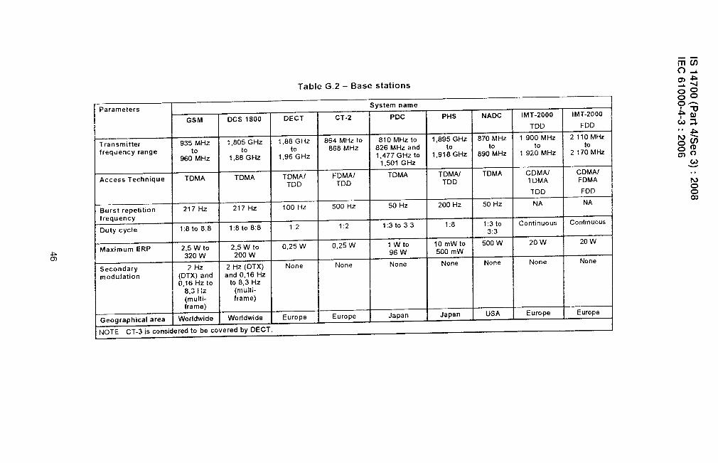
IIIll
h--
IS14700
(Part
4/See
3):2008
IEC
61000-4-3:2006
46

Table G.3 – Other RF devices
Parameters System name
RFID RTTT Wideband data Wideband data Wideband data Non specifictransmission transmission transmission short rangesystems and systems and systems and devicesHIPERLANs HIPERLANs HIPERLANs
transmitter 2446-2454 5795-5875 2400 -2483,5 5150-5350 5470-5725kequency
2400 -2483,5
5725-5875n MHz
hloduiation type FHSS if more than None FHSS None None None500 mW
Maximum ERP a ) 500 mW 2Wor8W 100 mW and 200 mW mean 1 W mean 10mW
b)4Wspectrum power
density25 mW
limitation
>uty cycle a)upto 100% No restrictions No restrictions No restrictions No restrictions No restrictions
b) <15 % within200 ms period
:hannel spacing None 5MHzor10 None None None None
MHz withinsome frequency
ranges
geographical area Worldwide Worldwide Worldwide Worldwide Worldwide Worldwide
. .No0co

IS 14700 (Part 4/See 3): 2008
IEC 61000-4-3:2006
Annex l-l(normative)
Alternative illumination method for frequencies above 1 GHz(“independent windows method”)
H.1 Introduction
When testing at frequencies above 1 GHz, the test distance shall be 1 m when using theindependent windows method (for example, the radio-telephone bands). Compliance with thefield uniformity requirement shall be verified for the selected test distance,
NOTE 1 With a test distance of 3 m, using an antenna with a narrow beam width or a ferrite-lined chamber atfrequencies above 1 GHz, it may be difficult to satisfy the field uniformity requirement over the 1,5 m x 1,5 mcalibration erea.
The alternative method for frequencies above 1 GHz divides the calibration area into asuitable array of 0,5 m x 0,5 m windows such that the whole area to be occupied by the faceof the EUT is covered (see Figures H.la and H.lb). The field uniformity shall beindependently calibrated over each window (see Figure H.2), using the procedure givenbelow. The field generating antenna shall be placed 1 m from the calibration area,
NOTE 2 Cable length end geometry are less critical at these high frequencies; therefore, the face area of the EUTis the determining factor for the size of the calibration area.
H.2 Calibration of field
The following steps shall be performed on each window:
a)
b)
c)
d)
e)
f)
position the field sensor at one of the four corners of the window
apply a forward power to the field generating antenna so that the field strength obtainedis in the range 3 V/m to 10 V/m, through the frequency range in steps of 1 ?Io of thestarting frequency (and thereafter the preceding frequency) and record both (power andfield strength) readings;
with the same forward power, measure and record the field strength at the remainingthree corners; all four field strengths shall lie within a range of O dB to 6 dB;
take the location with the lowest field strength as reference (this ensures that the ~ dB
requirement is met);
forward power and the field strength being known, the necessary forward power for therequired test field strength can be calculated (for example if, at a given point, 80 W gives9 V/m, then 8,9 W is needed for 3 V/m). The calculation shall be recorded;
repeat steps a) to e) for both horizontal and vertical polarizations.
The antennas and cables used for this uniform field calibration shall be used for testing.Therefore} the cable losses and the antenna factors of the field-generating antennas do nothave to be taken into consideration.
The position of the generating antennas and cables shall be recorded as precisely aspossible. Since even small displacements will significantly affect the field, the same positionsshall be used for testing.
48

IS 14700 (Part 4/See 3) :2008
IEC 61000-4-3:2006
During the test, at each frequency the forward power established in step e) above shall beapplied to the field-generating antenna. The test shall be repeated with the field-generatingantenna repositioned to illuminate each of the required windows in turn (see Figures H.1 andH 2).
n n,
01
Concept of windows
Window 7 I Window 8 ; Window 9 Q5M 1. Divide the calibration area into
I( )---”-----”+--------+-”----”--( )- 0’5 m x “5 m “ndows’2. Calibration IS required for all windows
1 1 ~,5m intended to be occupied by the face of the
( )f;~{af;~-< 3-1’ actua’EuTandc~’es’(In this example windows 1 to 3 and 5 are
~~~ used for calibration and test)
1
q v v@-0,5 m~0,5m~ 0,5 m-h
, I+1
0,8 m
-7%%m7JEC 03906
Figure H.la - Example of division for table-top equipment
n r-l . .. .v w
Wtndow 7 ~ Window 8 Window 9
, ,..~*,..< ,:;;
Window 4 / Window 5 / Window 6 0,5 m
( ‘{l ~
.. . .
J ~
----&-”---””--&--l “~ )“-{-00
Window 1 ~ Window 2 ! WmdoW3 0,5m
o 0 EUT
—II
19‘,-J $1
.. -
~0,5m i
‘ Ifi m+I I +
////////////////Chamber floor
Concept of windows
1, Divide the calibration area into0,5 m x 0,5 m windows,
2. Calibration is required for all windowsintended to be occupied by the face of theactual EUT and cables,
(In this example, windows 1 to 9 are used forcalibration and test)
Figure H.lb – Example of division for floor-standing equipment
Figure H.1 – Examp!es of division of the calibration area into 0,5 m x 0,5 m windows

IS 14700 (Part 4/See 3) :2008
IEC 61000-4-3:2006
..-.
Figure H.2 – Example of illumination of successive windows
50
MGIPF—6S5Dqm. of BISfZ~8— 16G9.21N8-300Books.

Bureau of Indian Standards
BIS is a statutory institution established under the Bureau of /ncf;an Standards Act, 1986 to promoteharmonious development of the activities of standardization, marking and quality certification of goodsand attending to connected matters in the country.
Copyright
51S has the copyright of all its publications. No part of these publications may be reproduced in anyform without the prior permission in wriiing of 61S. This does not preclude the free use, in course of
implementing the standard, of necessary details, such as symbols and sizes, type or grade
designations. Enquiries reiating to copyright be addressed to the Director (Publications), BIS.
Review of Indian Standards
Amendments are issued to standards as the need arises on the basis of comments. Standards are
also reviewed periodically; a standard along with amendments is reaffirmed when such reviewIr?dicates that no changes are needed; if the review indicates that changes are needed, it is taken up
fo: revision. Users of Indian Standards should ascertain that they are in possession of the latestamendments or edition by referring to the latest issue of ‘BIS Catalogue’ and ‘Standards: Monthly
Additions’.
This Indian Standard has been developed from Dot: No. LITD 09 (3016).
Amendments Issued Since Publication
Amendment No. Date of Issue Text Affected
————
BUREAU OF INDIAN STANDARDSHeadquarters:
Manak Bhavan, 9 Bahadur Shah Zafar Marg, New Delhi 110002Te/ephorres: 23230131, 23233375, 23239402 Website: www.bis.org.i~
Regional Offices: Telephones
Central : Manak Bhavan, 9 Bahadl;r Shah Zafar Marg
{
23237617NEW DELHI 110002 23233841
Eastern : 1/14, C,I.T. Scheme Vll M, V.I.P. Road, Kankurgachi
{
23378499, 23378561KOLKATA 700054 23378626, 23379120
Northern : SCO 335-336, Sector 34-A, CHANDIGARH 160022
{
2603843
2609285
Southern : C.I.T. Campus, IV Cross Road, CHENNAl 600113
{
22541216, 22541442
22542519, 22542315
Western : Manakalaya, E9 MlDC, Marol, Andheri (East)
{
2“832 9295, 28327858MUMBAI 400093 28327891, 28327892
Branches: AHMEDABAD. BANGALORE. BHOPAL. BHUBANE!3HWAR. COIMBATORE. FARIDABAD.
GHAZIABAD. GUWAHATI. HYDERABAD. JAIPUR. KANPUR. LUCKNOW. NAGPUR.PARWANOO. PATNA. PUNE. RAJKOT. THIRUVANANTHAPURAM. VI. SAKHAPATNAM.
[’pitli~ci b} the ivlana~cr, G(I\[. o]’ lndiil i)ress. Faridabad