Embed Size (px)
Citation preview
Inductors
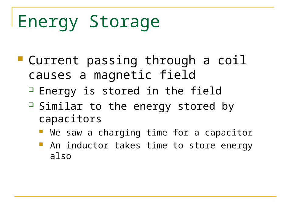
Energy Storage
Current passing through a coil causes a magnetic field Energy is stored in the field Similar to the energy stored by capacitors
We saw a charging time for a capacitor An inductor takes time to store energy also
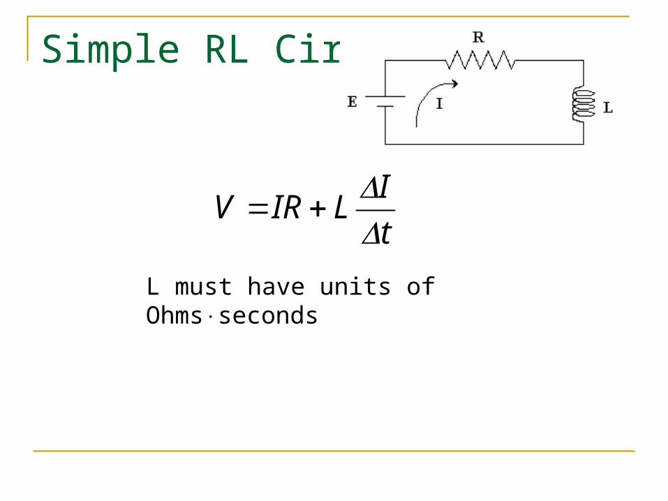
Simple RL Circuit
t
ILIRV
L must have units of Ohmsseconds
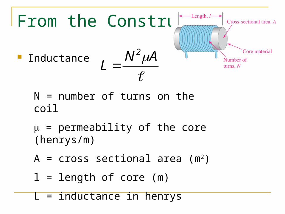
From the Construction
Inductance
AN
L2
N = number of turns on the coil
= permeability of the core (henrys/m)
A = cross sectional area (m2)
l = length of core (m)
L = inductance in henrys
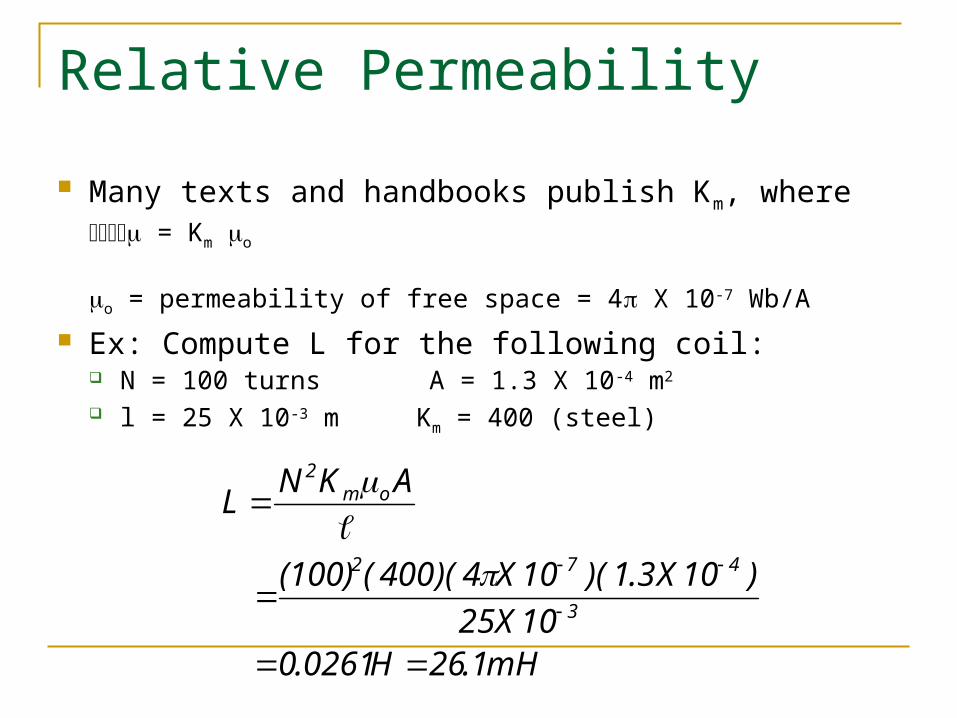
Relative Permeability
Many texts and handbooks publish Km, where = Km o
o = permeability of free space = 4 X 10⁻⁷ Wb/A
Ex: Compute L for the following coil: N = 100 turns A = 1.3 X 10⁻⁴ m2
l = 25 X 10-3 m Km = 400 (steel)
mH1.26 H0261.0 10X25
)10X3.1)(10X4)(400((100)
AKNL
3
472
om2
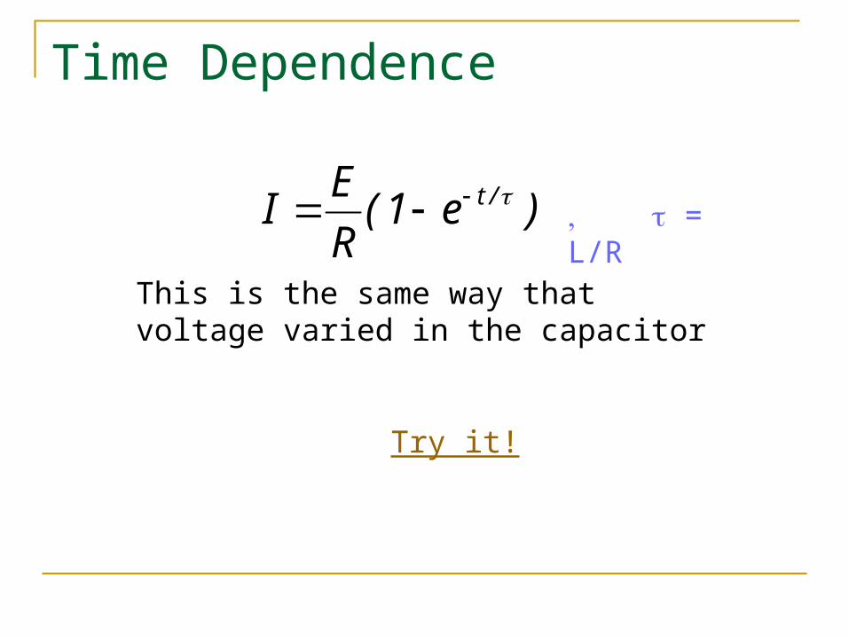
Time Dependence
)e1(R
EI /t = L/R
This is the same way that voltage varied in the capacitor
Try it!

Notes
The final current (E/R) doesn’t depend on L There is no voltage drop across the inductor after the full
current has been established The coil then acts as a short circuit (as if it weren’t there)
The inductance depends on the change of current (once I is established, I/t → 0 and V=IR)
At first I = 0, so V = IR = 0 As current rises the voltage drop across the resistor (IR)
gets greater, leaving less voltage to be dropped through the coil.
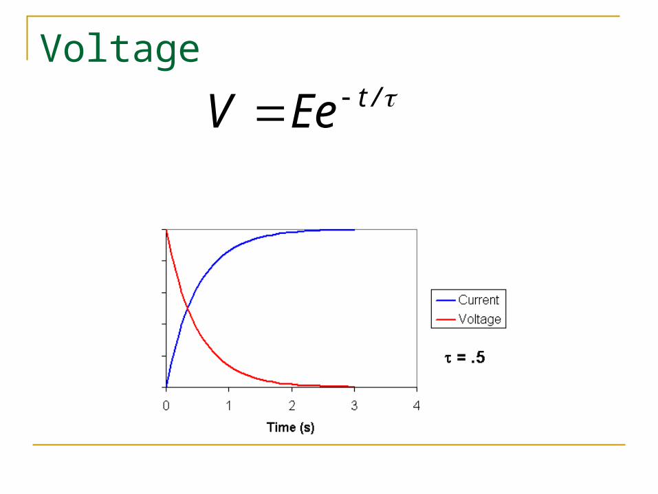
Voltage/tEeV
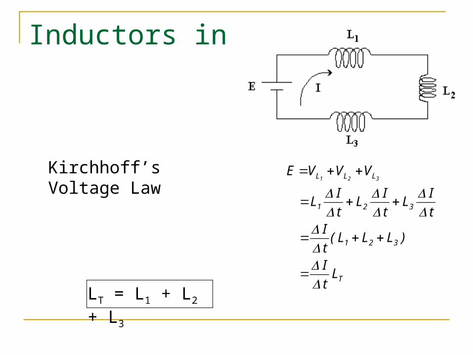
Inductors in Series
Kirchhoff’s Voltage Law
T
321
321
LLL
Lt
I
)LLL(t
I
t
I L
t
I L
t
I L
VVVE321
LT = L1 + L2 + L3
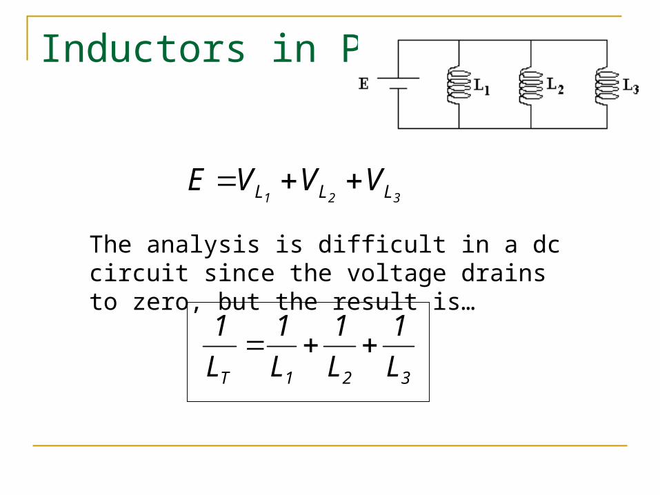
Inductors in Parallel
321 LLL VVVE
The analysis is difficult in a dc circuit since the voltage drains to zero, but the result is…
321T L
1
L
1
L
1
L
1
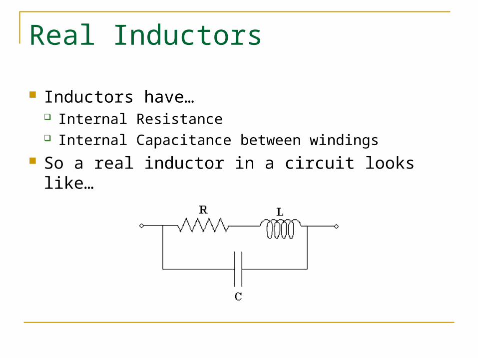
Real Inductors
Inductors have… Internal Resistance Internal Capacitance between windings
So a real inductor in a circuit looks like…
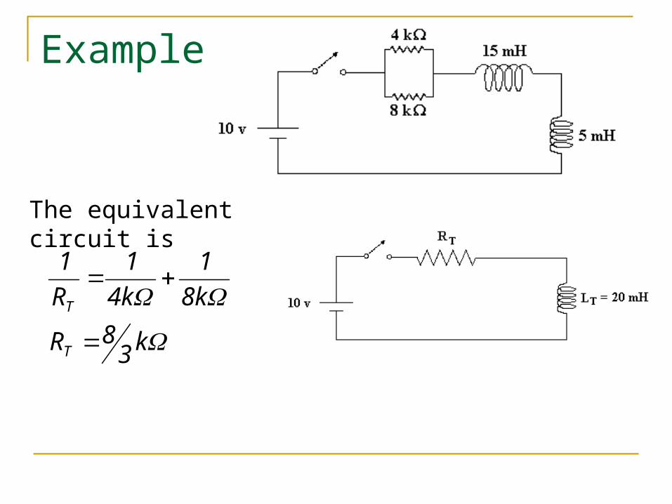
Example
The equivalent circuit is
k38R
k8
1
k4
1
R
1
T
T
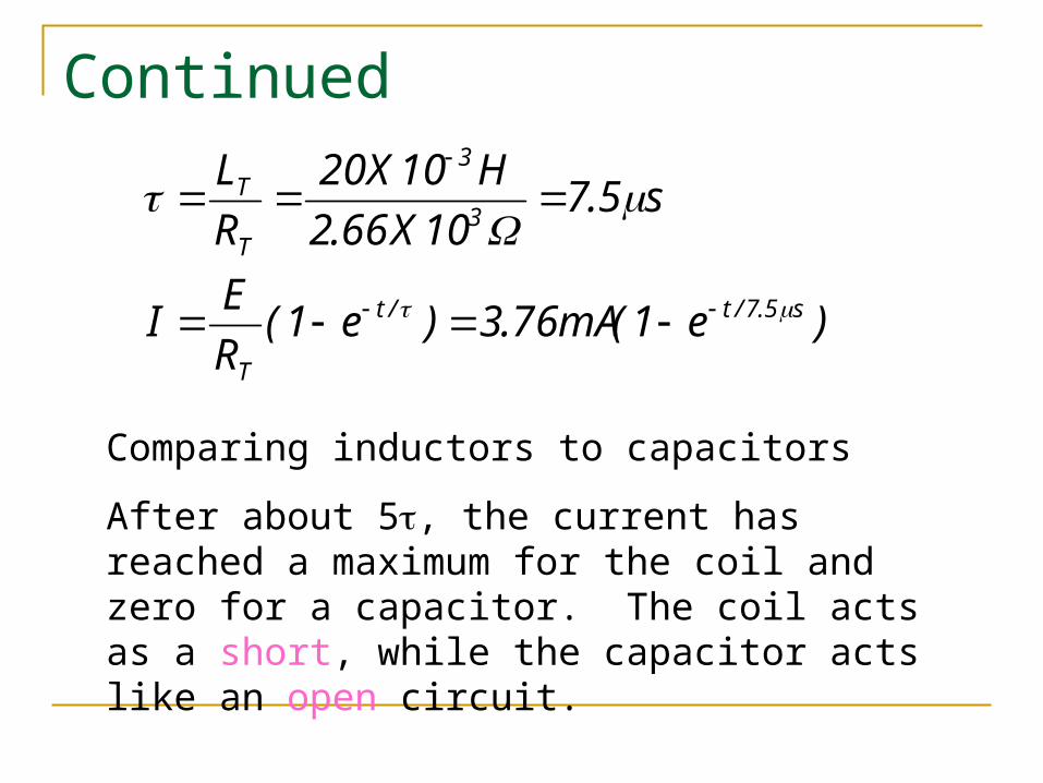
Continued
)e1(mA76.3)e1(R
EI
s5.710X66.2
H10X20
R
L
s5.7/t/t
T
3
3
T
T
Comparing inductors to capacitors
After about 5, the current has reached a maximum for the coil and zero for a capacitor. The coil acts as a short, while the capacitor acts like an open circuit.
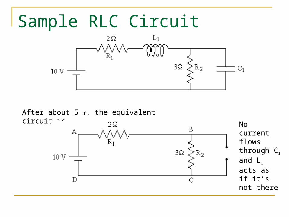
Sample RLC Circuit
After about 5 , the equivalent circuit is
No current flows through C1
and L1 acts as if it’s not there
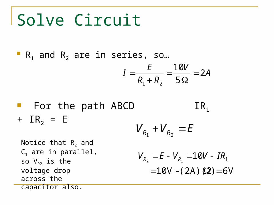
Solve Circuit
R1 and R2 are in series, so…
AV
RR
EI 2
5
10
21
For the path ABCD IR1 + IR2 = E
EVV RR 21
6V)(2A)(2-V 10
10 112
IRVVEV RR
Notice that R2 and C1 are in parallel, so VR2 is the voltage drop across the capacitor also.
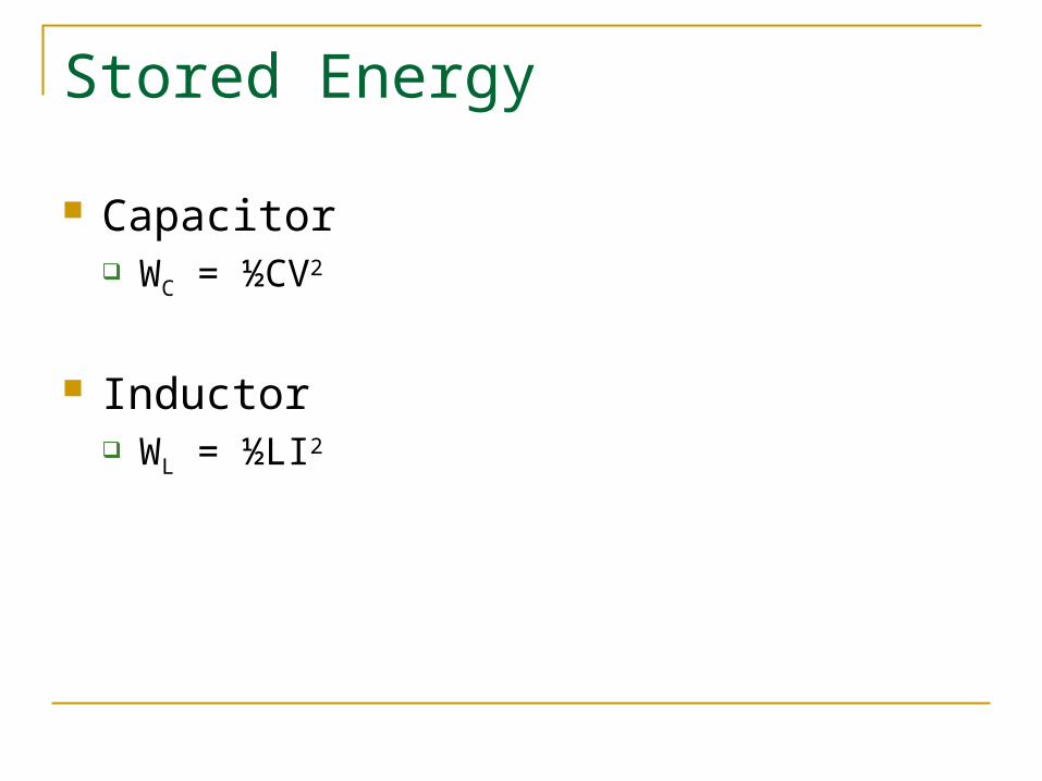
Stored Energy
Capacitor WC = ½CV2
Inductor WL = ½LI2