Embed Size (px)
Citation preview

www.deltaww.com
2016-10-19
DX-3001 Series Industrial 3G/WAN Cloud Router User Manual
Industrial Automation HeadquartersDelta Electronics, Inc. Taoyuan Technology CenterNo.18, Xinglong Rd., Taoyuan City, Taoyuan County 33068, TaiwanTEL: 886-3-362-6301 / FAX: 886-3-371-6301
AsiaDelta Electronics (Jiangsu) Ltd.Wujiang Plant 31688 Jiangxing East Road, Wujiang Economic Development ZoneWujiang City, Jiang Su Province, P.R.C. 215200TEL: 86-512-6340-3008 / FAX: 86-769-6340-7290
Delta Greentech (China) Co., Ltd.238 Min-Xia Road, Pudong District, ShangHai, P.R.C. 201209TEL: 86-21-58635678 / FAX: 86-21-58630003 Delta Electronics (Japan), Inc.Tokyo Office 2-1-14 Minato-ku Shibadaimon, Tokyo 105-0012, JapanTEL: 81-3-5733-1111 / FAX: 81-3-5733-1211
Delta Electronics (Korea), Inc.1511, Byucksan Digital Valley 6-cha, Gasan-dong, Geumcheon-gu, Seoul, Korea, 153-704TEL: 82-2-515-5303 / FAX: 82-2-515-5302
Delta Electronics Int’l (S) Pte Ltd.4 Kaki Bukit Ave 1, #05-05, Singapore 417939TEL: 65-6747-5155 / FAX: 65-6744-9228
Delta Electronics (India) Pvt. Ltd.Plot No 43 Sector 35, HSIIDC Gurgaon, PIN 122001, Haryana, India TEL : 91-124-4874900 / FAX : 91-124-4874945
AmericasDelta Products Corporation (USA)Raleigh OfficeP.O. Box 12173,5101 Davis Drive, Research Triangle Park, NC 27709, U.S.A.TEL: 1-919-767-3800 / FAX: 1-919-767-8080
Delta Greentech (Brasil) S.A.Sao Paulo OfficeRua Itapeva, 26 - 3° andar Edificio Itapeva One-Bela Vista01332-000-São Paulo-SP-BrazilTEL: 55 11 3568-3855 / FAX: 55 11 3568-3865
EuropeDelta Electronics (Netherlands) B.V.Eindhoven OfficeDe Witbogt 20, 5652 AG Eindhoven, The NetherlandsTEL : +31 (0)40-8003800 / FAX : +31 (0)40-8003898
*We reserve the right to change the information in this manual without prior notice.

1
DX-3001 Series Industrial 3G/WAN
Cloud Router User Manual Table of Contents
Chapter 1 Introduction
1.1 Product Overview ......................................................................................... 1-3
1.1.1 Network Design ..................................................................................... 1-3
1.1.2 Features .............................................................................................. 1-4
1.1.3 Front Panel Ports and LEDs ..................................................................... 1-5
1.1.4 Top Panel ............................................................................................. 1-5
1.1.5 Bottom Panel ........................................................................................ 1-6
1.1.6 Dimension ............................................................................................ 1-7
1.2 Package Checklist ........................................................................................ 1-7
Chapter 2 User Interface
2.1 Web-based GUI Configuration ........................................................................... 2-2
2.1.1 System Connection ................................................................................... 2-2
2.1.2 Default IP Address/Account/Password .......................................................... 2-2
2.1.3 Local Network Setups ................................................................................ 2-2
2.1.4 Logging in ............................................................................................... 2-4
2.2 DIADevice ...................................................................................................... 2-5
2.2.1 Device Connection and Detection ................................................................ 2-6
2.2.2 Network Setting ....................................................................................... 2-8
2.2.3 Bind Device ........................................................................................... 2-11
2.2.4 Open Device Webpage ............................................................................. 2-13
Chapter 3 Functions
3.1 Status ........................................................................................................ 3-2
3.1.1 Network Status ..................................................................................... 3-2
3.1.2 Device Information ................................................................................ 3-3
3.1.3 Local Log ............................................................................................. 3-4
3.1.4 Cloud Status ......................................................................................... 3-5

2
3.1.5 Connected Device .................................................................................. 3-5
3.2 Network ..................................................................................................... 3-5
3.2.1 Connection ........................................................................................... 3-5
3.2.2 Cellular Link1 ........................................................................................ 3-7
3.2.3 Cellular Link2 ...................................................................................... 3-10
3.2.4 WAN .................................................................................................. 3-12
3.2.5 LAN ................................................................................................... 3-14
3.3 Firewall .................................................................................................... 3-15
3.3.1 MAC Filter .......................................................................................... 3-15
3.4 System ..................................................................................................... 3-16
3.4.1 User Management ............................................................................... 3-16
3.4.2 Time Zone Configurations ..................................................................... 3-17
3.4.3 RS232 ............................................................................................... 3-17
3.4.4 RS485 ............................................................................................... 3-22
3.4.5 Modbus TCP ........................................................................................ 3-28
3.4.6 Firmware Upgrade ............................................................................... 3-31
3.4.7 Backup & Restore ................................................................................ 3-32
3.4.8 System Reboot ................................................................................... 3-32
3.4.9 Scheduled Jobs ................................................................................... 3-33
3.4.9.1 Add A New Job ............................................................................. 3-33
3.4.9.2 Export Job List ............................................................................. 3-34
3.4.9.3 Import Job List ............................................................................. 3-34
3.4.10 Network Diagnosis ............................................................................... 3-34
3.4.11 Privilege Management .......................................................................... 3-35
3.4.12 Event Management .............................................................................. 3-38
3.4.13 Register Management .......................................................................... 3-42
3.5 Cloud Service ............................................................................................ 3-43
3.5.1 Cloud Service ..................................................................................... 3-43
3.5.2 Proxy Setting ...................................................................................... 3-48
3.5.3 Secure Tunnel Firewall ......................................................................... 3-49
3.5.4 Cloud Log ........................................................................................... 3-50
Chapter 4 DIACom
4.1 Introduction to DIACom ................................................................................ 4-2
4.1.1 Select a Suitable Firmware Version .......................................................... 4-2

3
4.1.2 DIACom Installation ............................................................................... 4-3
4.1.3 DIACloud Account Registration ................................................................ 4-3
4.1.4 Bind DIACloud Account .......................................................................... 4-5
4.2 DIACom Operation ....................................................................................... 4-6
4.2.1 Setup a Secure Tunnel ........................................................................... 4-6
4.2.2 Create a Virtual Serial-port ................................................................... 4-11
4.2.3 Remote Control and Monitoring via DIACom ............................................ 4-12
4.2.4 Automation Startup ............................................................................. 4-14
Chapter 5 DIACloud
5.1 Introduction to DIACloud .............................................................................. 5-2
5.1.1 Select a Suitable Firmware Version .......................................................... 5-2
5.2 Instructions for DIACloud .............................................................................. 5-2
5.2.1 Register and Login ................................................................................. 5-2
5.2.2 Home .................................................................................................. 5-4
5.2.3 Devices ................................................................................................ 5-6
5.2.4 Alarm ................................................................................................ 5-16
5.2.5 Secure Tunnels ................................................................................... 5-17
5.2.6 Sub Users .......................................................................................... 5-19
5.2.7 Logs .................................................................................................. 5-22
5.2.8 Orders ............................................................................................... 5-23
5.2.9 Profile ................................................................................................ 5-24
Chapter 6 DIACloud
6.1 Introduction to DIACloud APP ........................................................................ 6-2
6.1.1 Select a Suitable Firmware Version .......................................................... 6-2
6.1.2 DIACloud APP Installation ....................................................................... 6-2
6.2 DIACloud APP Function ................................................................................. 6-3
6.2.1 DIACloud APP Login ............................................................................... 6-3
6.2.2 Device List ........................................................................................... 6-4
6.2.3 Device Details ....................................................................................... 6-5
6.2.4 Registers View ...................................................................................... 6-6
6.2.5 Alarm List ............................................................................................ 6-7

1-1
1 Chapter 1 Product Introduction
Table of Contents
1.1 Product Overview ....................................................................................... 1-4 1.1.1 Network Design ..................................................................................... 1-5 1.1.2 Features ............................................................................................... 1-5 1.1.3 Front Panel Ports and LEDs ..................................................................... 1-6 1.1.4 Top Panel ............................................................................................. 1-6 1.1.5 Bottom Panel ........................................................................................ 1-7 1.1.6 Dimension ............................................................................................ 1-8
1.2 Package Checklist ...................................................................................... 1-8

DX-3001 Series Industr ia l Cloud Router
1-2
_1 About This Manual
The user manual is suitable for DX-3001H9. If you need to use the Delta DX-2100/2300 series products in China areas,
please refer to the model name DX-2100RW-WW/ DX-2300LN-WW on the Delta website, or contact our branch offices or
distributors.
FCC Interference Statement
This equipment has been tested and found to comply with the limits for a class A digital device, pursuant to part 15 of the
FCC Rules. These limits are designed to provide reasonable protection against harmful interference in a residential
installation.
This equipment generates radio frequency signal and, if not installed and used in accordance with the instructions, may cause harmful interference to radio communications. However, there is no guarantee that interference will not occur in a particular installation. If this equipment does cause harmful interference to radio or television reception, which can be determined by turning the equipment off and on, the user is encouraged to try to correct the interference by one or more of the following measures:
---Reorient or relocate the receiving antenna.
---Increase the separation between the equipment and receiver.
---Connect the equipment into an outlet on a circuit different from that to which the receiver is connected.
---Consult the dealer or an experienced radio/TV technician for help.
CE Declaration of Conformity
DX-3001H9-V is herewith confirmed to comply with the requirements set out in the Council Directive on the
Approximation of the Laws of the Member States relating to Electromagnetic Compatibility of Radio and Telecom device
(1995/5/EC). For the evaluation regarding the Directives, the following standards were applied:
Test Items : ---EMC EN 301 908-1 V7.1.1(2015-03) EN 301 511 V12.1.1(2015-06) ---Radio EN 301 489-1 V1.9.2 (2011-09) EN 301 489-7 V1.3.1 (2005-11) EN 301 489-24 V1.5.1 (2010-10) ---MPE EN50385: 2002 ---Safety EN60950-1: 2006/A11:2009/A1:2010/A12:2011/A2:2013

Chapter 1 Product Introduct ion
1-3
1_ EN 55022 Class A Warning: Class A ITE is a category of all other ITE which satisfies the class A ITE limits but not the class B ITE limits.
The following warning shall be included in the instructions for use:
Warning
This is a class A product. In a domestic environment this product may cause radio interference in which case
the user may be required to take adequate measures.
EN 55032 Class A Warning:
Class A ITE is a category of all other ITE which satisfies the class A ITE limits but not the class B ITE limits.
The following warning shall be included in the instructions for use:
Warning: This equipment is compliant with Class A of EN 55032. In residential environment this equipment may cause
radio interference.

DX-3001 Series Industr ia l Cloud Router
1-4
_1 1.1 Product Overview
DX-3001H9 is an industrial router, it has 2 SIM card slots and supports multiple mobile networks like WCDMA, UMTS,
HSUPA, GSM, GPRS, and EDGE. When one cellular network fails to work, the device will automatically switch to the
other cellular network. Besides the two cellular network connections, the WAN port can be another connection to Internet.
Priorities of the connection to Internet over WAN and 2 cellular networks are configurable. As there is only one 3G module
in the device, the two cellular networks cannot be active at the same time. Moreover, the product is equipped with multiple
application interfaces, including Ethernet interface, RS232 serial interface and RS485 serial interface, and thus can satisfy
the user’s various different application demands.
The product supports DIACloud platform services, and by this platform, convenient and efficient point-to-point connection
with the router, safe and reliable data transmission, remote device management and configuration, remote firmware
upgrading, remote maintenance and other functions can be realized, so as to save the cost of device operation and
maintenance for users.
The product can be widely used in the fields requiring mobile network interconnection, such as industrial automation,
smart home, intelligent building, smart power grids, mobile video surveillance, intelligent self-service and intelligent
transportation.

Chapter 1 Product Introduct ion
1-5
1_ 1.1.1 Network Design
DIACloud platform services supported, users can connect intelligent devices from different locations to the internet with
DX-3001H9 and use point-to-point connection with the router for a safe and reliable data transmission and additionally
save the costs of VPN device operation as well as maintenance. By browsing the web or apps on the handheld computers,
managers can check the data and monitor the devices remotely in real-time
1.1.2 Features
HSPA+/HSUPA/HSDPA/UMTS: 800/850/900/1700(AWS)/1900/2100 MHz
GSM/GPRS/EDGE: 850/900/1800/1900 MHz
Authentication Protocols, CHAP and PAP
Access Point Name (APN) gateway
Automatic redial when connection is broken
Dual SIM card slots, support auto-switching between the cellular operators
WAN port access mode(static IP , DHCP client)
Provide Dual Port RS232 & RS485 and LAN Port Interfaces for Different Application Demands
Built-in a Watchdog Timer to Ensure System Stability
Built-in RTC and Support NTP Server
Firmware Upgrade Locally and Remotely
Support MAC Address Filtering
Support DHCP Server
Support Dynamic DNS
Various Protocols, TCP/IP, UDP, ICMP, DHCP, HTTP, DNS, SSH and More
Modbus TCP, Modbus ASCII and Modbus RTU protocol
Scheduled Task Management
Servers for Local Log and Remote Log
Configurations Backup, Export and Import
Network Flow Monitoring

DX-3001 Series Industr ia l Cloud Router
1-6
_1 Network Fault Detection and Diagnosis
DIACloud Service to Secure Point-to-point Data Transmission, to Manage Device Configurations Piece by
Piece or in Batch and to Upgrade Firmware Remotely
1.1.3 Front Panel Ports and LEDs
1.1.4 Top Panel

Chapter 1 Product Introduct ion
1-7
1_ 1.1.5 Bottom Panel
Notice This router’s reset button is on the front panel. By pressing the Reset button, users can reset the router or
reset the router to factory default settings. See the instruction below:
Reset the Router: With the router powered on, press the Reset button and release the button right
away.
Reset to Factory Defaults: With the router powered on, press and hold the Reset button for 3~6
seconds and then release the button.
Reset can only be done when the device is running properly.
With the router powered on, press and hold the Reset button until all the LEDs go out (except
the Power LED). Then release the button and wait the router to reboot to its factory default
settings.

DX-3001 Series Industr ia l Cloud Router
1-8
_1 1.1.6 Dimension
Unit = mm
1.2 Package Checklist Unpack the package carefully and check the package contents. The package should contain the following items:
DX-3001H9 Industrial 3G Cloud Router x 1
Quick Installation Guide x 1
SMA Antenna (300cm) x 1
Notice Verify that nothing is missing from the DX-3001H9 package by using the check list above. If any item is found missing or damaged, please contact your local sales representative for support.

2-1
2 Chapter 2 User Interface
Table of Contents
2.1 Web-based GUI Configuration ....................................................................... 2-2 2.1.1 System Connection ................................................................................... 2-2 2.1.2 Default IP Address/Account/Password .......................................................... 2-2 2.1.3 Local Network Setups ................................................................................ 2-2 2.1.4 Logging in ................................................................................................ 2-4
2.2 DIADevice ..................................................................................................... 2-5 2.2.1 Device Connection and Detection ................................................................ 2-6 2.2.2 Network Setting ........................................................................................ 2-8 2.2.3 Bind Device ............................................................................................ 2-11 2.2.4 Open Device Webpage ............................................................................. 2-13

DX-3001 Series Industr ia l Cloud Router
2-2
_2
2.1 Web-based GUI Configuration The DX-3001H9 Industrial 3G Cloud Router provides a friendly Web Browser Configuration for users to set up and operate more intruitivly.
2.1.1 System Connection Connect the DX-3001H9 with a computer directly or via a switch/hub.
2.1.2 Default IP Address/Account/Password The default domain name of router is www.diadevice.com, default IP address is 192.168.1.1. The initial account and password is admin/admin
2.1.3 Local Network Setups After the connection of the local computer and the router is done, you will need to set the network configruration for your computer. There are 2 methods for the setting, we prefer you use the first one:
Obtain an IP address automatically by using the router as a DHCP server.
1. Open Network Connections by clicking the Start button , and then clicking Control Panel.
2. Under Network and Sharing Center, click View network connections.
3. Right-click the connection that you want to change, and then click Properties. If you're prompted for an administrator password or confirmation, type the password or provide confirmation.
4. Click the Networking tab. Under This connection uses the following items, click either Internet Protocol Version 4 (TCP/IPv4) or Internet Protocol Version 6 (TCP/IPv6), and then click Properties.

Chapter 2 Introduct ion to User Inter face
2-3
2_
5. Click Obtain DNS server address automatically and then click OK to get a DNS server address automatically using DHCP.
Set up the IP address manually. (The IP address of the computer should be in the same subnet as the router’s.)

DX-3001 Series Industr ia l Cloud Router
2-4
_2
Since the router’s default IP address is 192.168.1.1 and the subnet mask is 255.255.255.0, the computer’s IP address can be set between 192.168.1.2 to 192.168.1.254. However, you’ll need to make sure there are no IP conflicts.
Here, we set the address to 192.168.1.10 and the default gateway to 192.168.1.1. For DNS, the usable DNS address can be selected or the address can also be set to 192.168.1.1.
2.1.4 Logging in 1. Open your Internet Explorer browser and input LAN IP address (Default is 192.168.1.1) or the router’s domain name
(www.diadevice.com) in the search bar and then press Enter.
2. You’ll be prompted with the log-in page. Input the user name and the password (Default is admin/admin) and then press Enter to log in to the setup page.

Chapter 2 Introduct ion to User Inter face
2-5
2_
3. After login, you can see the main selection area on the left hand side and the upper area of the page. The detailed settings can be seen on the right hand side of the page.
Notice
Considerations of the router LAN port IP will be change after the device is bind with DIACloud account, we prefer you use 192.168.1.1 and use the automatically obtained IP address and DNS server for the computer
2.2 DIADevice DIADevice is a tool for quickly configuring network devices. Users simply connect the DX device to the PC through the network cable. This tool can be used to quickly and easily configure the network setting of the device and complete the device binding DIACloud cloud account.
The DIADevice software is included in the latest DIACom software package. From the official website or sales staff to obtain DIACom packag. DX-3001 below as an example on how to configure the device through DIADevice.
The following example uses DX-3001 to show you how to configure your device with DIADevice.

DX-3001 Series Industr ia l Cloud Router
2-6
_2
2.2.1 Device Connection and Detection 1. Connect the device to the power supply, and connect the device to the PC using a network cable. Plug the network
cable connected to the Internet into the WAN port of the device
2. Run DIADevice software, click "Detect” button.
3. After DIACom detects the device, it will automatically go to the login page, and the user needs to enter login password on the login page.

Chapter 2 Introduct ion to User Inter face
2-7
2_
4. After passing the authentication, the device information page is displayed, including the basic device information (Device Name, S / N, firmware, LAN IP address), network status, WAN information, and cloud service information

DX-3001 Series Industr ia l Cloud Router
2-8
_2
2.2.2 Network Setting This feature allows you to quickly configure your network in two steps.
1. Click “Network Setting”
2. You can setup the connection priority here, and then, it will guide you to config each the connection parameter page
base on the priority what you setup.
3. WAN setting page and Proxy setting page(if need)

Chapter 2 Introduct ion to User Inter face
2-9
2_
4. Cellular setting page

DX-3001 Series Industr ia l Cloud Router
2-10
_2
5. After the device successfully connected to the Internet, the connection was successful.

Chapter 2 Introduct ion to User Inter face
2-11
2_
2.2.3 Bind Device This feature allows you to quickly bind your device to the DIAcloud in three steps.
1. Click “Bind Device”
2. Enter the DIAcloud account number and password, and click Next.
3. After binding configuration is configured, click “Bind” to bind.

DX-3001 Series Industr ia l Cloud Router
2-12
_2
4. If your device is successfully bound to the cloud, the following screen will appear
Notice If the device has been bound to the cloud account, you need to switch to another cloud account binding, you only need to repeat 1-3 steps and then enter the new cloud account you need to bind.

Chapter 2 Introduct ion to User Inter face
2-13
2_
2.2.4 Open Device Webpage Click open device webpage button, the browser will open the device settings page, the user can set the parameters of RS232 / 485 configuration.

3-1
Chapter 3 Functions
Table of Contents
3.1 Status ........................................................................................................ 3-3 3.1.1 Network Status ..................................................................................... 3-3 3.1.2 Device Information ................................................................................ 3-4 3.1.3 Local Log .............................................................................................. 3-5 3.1.4 Cloud Status ......................................................................................... 3-6 3.1.5 Connected Device .................................................................................. 3-6
3.2 Network ..................................................................................................... 3-6 3.2.1 Connection ........................................................................................... 3-6 3.2.2 Cellular Link1 ........................................................................................ 3-8 3.2.3 Cellular Link2 ...................................................................................... 3-11 3.2.4 WAN .................................................................................................. 3-13 3.2.5 LAN ................................................................................................... 3-15
3.3 Firewall .................................................................................................... 3-16 3.3.1 MAC Filter .......................................................................................... 3-16
3.4 System ..................................................................................................... 3-17 3.4.1 User Management ................................................................................ 3-17 3.4.2 Time Zone Configurations ..................................................................... 3-18 3.4.3 RS232 ............................................................................................... 3-18 3.4.4 RS485 ............................................................................................... 3-23 3.4.5 Modbus TCP ........................................................................................ 3-29 3.4.6 Firmware Upgrade ............................................................................... 3-32 3.4.7 Backup & Restore ................................................................................ 3-33 3.4.8 System Reboot .................................................................................... 3-33 3.4.9 Scheduled Jobs ................................................................................... 3-34
3.4.9.1 Add A New Job ............................................................................. 3-34 3.4.9.2 Export Job List .............................................................................. 3-35 3.4.9.3 Import Job List ............................................................................. 3-35
3.4.10 Network Diagnosis ............................................................................... 3-35 3.4.11 Privilege Management .......................................................................... 3-36 3.4.12 Event Management .............................................................................. 3-39 3.4.13 Register Management .......................................................................... 3-43
3.5 Cloud Service ........................................................................................... 3-44
3

DX-3001 Series Industr ia l Cloud Router
3-2
3.5.1 Cloud Service ..................................................................................... 3-44 3.5.2 Proxy Setting ...................................................................................... 3-49 3.5.3 Secure Tunnel Firewall ......................................................................... 3-50 3.5.4 Cloud Log ........................................................................................... 3-51

CH3 Functions
3-3
_3
3.1 Status You can view summary or detailed information on the Network Status, Device Information, Local Log, Cloud Status, and Connected Device.
3.1.1 Network Status This page shows basic information on Connection Status, LAN Status and traffic statistics.
When router connects to internet by WAN port, the status includes the connection type, WAN mode, IP Address, Network Mask, Gateway Address, primary DNS, and Secondary DNS.
When router connects to internet by Cellular, the status includes the Operator, APN, User Name, Password, MCC, MNC, Signal Strength, authorization mode, dial-up number, Online Duration, IP Address, Network Mask, Gateway Address, primary DNS, and Secondary DNS.
LAN includes the LAN IP Address, and connection status of 4 LAN port. Up means connected, down means disconnected.
Traffic statistics shows network traffic information of the Cellular Link 1&2 and WAN port.

DX-3001 Series Industr ia l Cloud Router
3-4
_3
3.1.2 Device Information This page shows basic information on the Hardware/Software version and Resource Usage Information.
Basic Information
Item Description
Device Type Model type of the router
Device Name Name of the router, the default is DX3001 + “_” + “the last four digits of Mac address”
S/N Serial number of the router
Version Information
Item Description
Hardware Version Version number of the hardware currently used on the router

Chapter 3 Introduct ion to Funct ions
3-5
_3
Release Date Hardware release date
Current Version Version number of the software currently used on the router
Upgrade Date Upgrade time of the software currently used on the router
Resource Usage Information
Item Description
CPU Usage The CPU usage of current router
Total Memory The total memory on the router
Memory Used The memory currently used on the router.
Memory Usage The current ratio of the router usage
3.1.3 Local Log This page shows logs of the router, including the System log, Warning lot and the Debug log. You can use the buttons on the right hand side to refresh, clear or download the displayed logs.

DX-3001 Series Industr ia l Cloud Router
3-6
_3
3.1.4 Cloud Status This page shows cloud server information of the router, including the Registration Status, Service Status, and Activated Time.
3.1.5 Connected Device This page shows information of the devices connected to the router, including the IP Address, Host Name, MAC Address.
3.2 Network You can set up networks configuration, including the connection priority, Cellular network, WAN and LAN Configurations.
3.2.1 Connection This page is used for setting up the connection priority. Router provide 3 links to connect to Internet, include cellular network 1&2 and WAN, user can appoint the connect order in this page.

Chapter 3 Introduct ion to Funct ions
3-7
_3
Description Default
Primary Connection
Appoint first interface for internet connection WAN
Secondary Connection
Set up an IP address for your device. Disabled
Tertiary Connection
Set up the LAN network mask. Disabled
Auto Detect
Check if the connection is dropped or not via PING Disabled
Target Address 1
Set the first IP/domain of the server that program will do a ping testing. N/A
Target Address 1
Set the second IP/domain of the server that program will do a ping testing. N/A
Dial Failure To Restart
Enable or disable the function if the dial failure will be in the default time to Disabled

DX-3001 Series Industr ia l Cloud Router
3-8
_3
Description Default
restart device.
Detect Interval
Set the ping test interval 60s
WAN Backup
When the 3G dial-up is successful, the system will periodically check the status of the WAN. If it detects that the WAN connection is available, it will automatically switch to the WAN connection to reduce the traffic loss of 3G
Disable
Wan Check Interval
Set the interval for detecting WAN connection status 10s
3.2.2 Cellular Link1 This page is used for setting up the Cellular Network for SIM1, including the Operator, User Name, Password, APN, Authorization Mode, Dial-Up Number, Dial-Up Mode, Redial Interval, Redial Times, Max Idle Time, Connection Check Interval, Connection Check Times, and MTU.

Chapter 3 Introduct ion to Funct ions
3-9
_3
Description Default
Operator
Select Auto or Others for the Operator from the dropdown list.
Auto: the system will detect the operator from the inserted SIM card and set up accordingly.
Others: users can set up the operator manually.
AUTO
User Name
This name is provided by the operator. When “Auto” is selected, the system will set the name up automatically and users cannot change the setting.
N/A
Password
This password is provided by the operator. When “Auto” is selected, the system will set the password up automatically and users cannot change the setting.
N/A
APN (Access Point Name)

DX-3001 Series Industr ia l Cloud Router
3-10
_3
Description Default
This APN is provided by the operator. When “Auto” is selected, the system will set the APN up automatically and users cannot change the setting.
3gnet
Authorization Mode
Options are “Auto”, “PAP” and “CHAP”. Auto
Dial-Up Number
This number is provided by the operator. When “Auto” is selected, the system will set the number up automatically and users cannot change the setting.
*99#
Dial-Up Mode
Options are :
Always online: stay connected and once a disconnection is detected, the router will redial to connect automatically.
On-demand connection: redial when connection to the internet is on demand.
Manual connection: users dial to connect and when it fails to connect, it will not redial.
Always online
Redial Interval
Set up the time to redial when the system fails to connect. This will only be executed when the option “Always online” or “On-demand connection” is selected.
30
Redial Times
Set up the maximum redial time, 0 indicating infinity. This will only be executed when the option “Always online” or “On-demand connection” is selected.
0
Max Idle Time
Set up the maximum idle time. When the idle time exceeds the set value, the router will disconnect and then redial, 0 indicating not to disconnect.
0
Connection Check Interval
Set up the connection check interval. Check the connectivity, if the connection is lost, it will redial automatically, 0 indicating not to check the connectivity.
60
Connection Check Times
Set up the connection check times, 0 indicating infinity. Once a disconnection is detected, and the option “Always online” or “On-demand connection” is selected, the router will redial according to the set value in the Redial Times.
5
MTU
Maximum Transmission Unit is the largest packet that can be transmitted over packet based networks.
1492

Chapter 3 Introduct ion to Funct ions
3-11
_3
3.2.3 Cellular Link2 This page is used for setting up the Cellular Network for SIM2, including the Operator, User Name, Password, APN, Authorization Mode, Dial-Up Number, Dial-Up Mode, Redial Interval, Redial Times, Max Idle Time, Connection Check Interval, Connection Check Times, and MTU.
Description Default
Operator
Select Auto or Others for the Operator from the dropdown list.
Auto: the system will detect the operator from the inserted SIM card and set up accordingly.
Others: users can set up the operator manually.
AUTO
User Name
This name is provided by the operator. When “Auto” is selected, the system N/A

DX-3001 Series Industr ia l Cloud Router
3-12
_3
Description Default
will set the name up automatically and users cannot change the setting.
Password
This password is provided by the operator. When “Auto” is selected, the system will set the password up automatically and users cannot change the setting.
N/A
APN (Access Point Name)
This APN is provided by the operator. When “Auto” is selected, the system will set the APN up automatically and users cannot change the setting.
3gnet
Authorization Mode
Options are “Auto”, “PAP” and “CHAP”. Auto
Dial-Up Number
This number is provided by the operator. When “Auto” is selected, the system will set the number up automatically and users cannot change the setting.
*99#
Dial-Up Mode
Options are :
Always online: stay connected and once a disconnection is detected, the router will redial to connect automatically.
On-demand connection: redial when connection to the internet is on demand.
Manual connection: users dial to connect and when it fails to connect, it will not redial.
Always online
Redial Interval
Set up the time to redial when the system fails to connect. This will only be executed when the option “Always online” or “On-demand connection” is selected.
30
Redial Times
Set up the maximum redial time, 0 indicating infinity. This will only be executed when the option “Always online” or “On-demand connection” is selected.
0
Max Idle Time
Set up the maximum idle time. When the idle time exceeds the set value, the router will disconnect and then redial, 0 indicating not to disconnect.
0
Connection Check Interval
Set up the connection check interval. Check the connectivity, if the connection is lost, it will redial automatically, 0 indicating not to check the connectivity.
60
Connection Check Times

Chapter 3 Introduct ion to Funct ions
3-13
_3
Description Default
Set up the connection check times, 0 indicating infinity. Once a disconnection is detected, and the option “Always online” or “On-demand connection” is selected, the router will redial according to the set value in the Redial Times.
5
MTU
Maximum Transmission Unit is the largest packet that can be transmitted over packet based networks.
1492
3.2.4 WAN This page is used for setting up the WAN, including the IP address, network mask, gateway and DNS.
Description Default
WAN Mode
Your device can connect to the internet via the WAN port with a Dynamic IP or Static IP.
Static IP: Manually set up the IP address.
Dynamic IP: DHCP (Dynamic Host Configuration Protocol) allows you to
DHCP

DX-3001 Series Industr ia l Cloud Router
3-14
_3
Description Default
obtain an IP address automatically from your router.
IP Allocation Method
The IP Allocation Method is the same as the WAN Connection Mode that you have set. You can apply to different option by modifying the WAN Connection Mode.
Dynamic: Dynamic Host Configuration Protocol (DHCP) allows you to obtain an IP address automatically from your router.
Manual: Manually set up the IP address (Static).
DHCP
IP Address
Set up an IP address for your device to connect to the internet via the WAN port. It’s configurable when the mode is set to Static.
0.0.0.0
Network Mask
Set up the WAN network mask. It’s configurable when the mode is set to Static.
0.0.0.0
Gateway Address
Set up the gateway address. It’s configurable when the mode is set to Static. 0.0.0.0
MTU
Maximum Transmission Unit is the largest packet that can be transmitted over packet based networks.
1500
Retrieve DNS Address By
The Retrieve DNS Address Method is the same as the WAN Connection Mode that you have set. You can apply to different option by modifying the WAN Connection Mode.
DNS address can be retrieved by DHCP setup or manually set.
Dynamic: Dynamic Host Configuration Protocol (DHCP) allows you to
obtain an IP address automatically from your router.
Manual: Manually set up the IP address (Static).
DHCP
Primary DNS
Set up the primary DNS. It’s configurable when the mode is set to Static. 0.0.0.0
Secondary DNS
Set up the secondary DNS. It’s configurable when the mode is set to Static. 0.0.0.0

Chapter 3 Introduct ion to Funct ions
3-15
_3
3.2.5 LAN This page is used for setting up the LAN, including IP Address, Network Mask, and DHCP Server.
Description Default
IP Address
Set up an IP address for your device. 192.168.1.1
Network Mask
Set up the LAN network mask. 255.255.255.0
DHCP Server
If DX router uses DHCP to assign IP addresses automatically on your network, you can specify the IP address range and lease time for the clients on your network. Once the DX router have bound the DIACloud and enabled the DIACloud DHCP, the DHCP in DX router will be disabled automatically.
Enable
Address Lease Time
To set up the address lease time so that a client doesn't hold an IP address indefinitely. It allows for a mechanism to gracefully reuse DHCP addresses. Options here are 1 to 3 days.
One day
First IP Address
To increase the number of addresses available to clients, you can change the Start Address.
192.168.1.100

DX-3001 Series Industr ia l Cloud Router
3-16
_3
Description Default
Last IP Address
To increase the number of addresses available to clients, you can change the End Address.
192.168.1.200
STP
STP is a network protocol that builds a logical loop-free topology for Ethernet networks. The basic function of STP is to prevent bridge loops and the broadcast radiation that results from them. If this STP is enabled, the traffic usage will increase about 15Mbit in 24 hours.
Disable
3.3 Firewall 3.3.1 MAC Filter This page is used for setting up the MAC Filter, including configuring the MAC Address, Device Name and Status.
MAC Filter is used to block particular MAC address from the local network. Select Enable/Disable to activate/deactivate this functionality. Click the “Add A MAC Address” to block the MAC Address.
After clicking the “Add A MAC Address”, you will see the following page.
Description Default
MAC Address
Manually input the MAC address that you’d like to block. N/A
Device Name
Set up the device name corresponding to the set MAC address. N/A
Status

Chapter 3 Introduct ion to Funct ions
3-17
_3
Description Default
Enable/disable the MAC Filter functionality. Enabled
3.4 System You can set up the system configurations, including the User Management, Time Zone Configurations, RS232, RS485, Modbus TCP, Log Setting, Firmware Upgrade, Backup & Restore, Scheduled Jobs, Network Diagnosis, System Reboot, Event Management, and Register Management.
3.4.1 User Management You can change the administrator password and set up web page session timeout here. The password must be a combination of 5 to 12 characters, numbers and/or underline symbols.
Description Default
Old Password
Input the original password. admin
New Password
Input the new password you’d like to use. The password length should be 5-12 digits and is composed of lowercase letters, uppercase letters (case sensitive), numerals 0-9 and underline.
N/A
Confirm Password
Again input the password you’d like to use to double confirm there is no typo. N/A
Session Timeout

DX-3001 Series Industr ia l Cloud Router
3-18
_3
Description Default
Session timeout is an expired time limit for a logged in user which as been inactive for a period of time. Setting range is from 10 to 1440 minutes
30
3.4.2 Time Zone Configurations You can change the current time of the device. Use the dropdown list to select the correct time zone for your device.
Description Default
The current time of device
Here shows the current time of your device. N/A
Local PC Time
Here shows the current time of your local PC which connect to the device
Set Local PC Time
Set the router time same as the PC time N/A
Time Zone Setting
Select the operating time zone of your device: GMT-12:00 - GMT+13:00. N/A
3.4.3 RS232 RS232 (Recommended Standard - 232) is a telecommunication standard for binary serial communications between
devices. You can set up the configurations for RS232, including Baud Rate, Data Bits, Stop Bits, Parity Bits and Flow Control.

Chapter 3 Introduct ion to Funct ions
3-19
_3

DX-3001 Series Industr ia l Cloud Router
3-20
_3

Chapter 3 Introduct ion to Funct ions
3-21
_3
Description Default
Working Mode
Select the working mode for the current active serial port.
Transparent mode: This mode is suitable for uploading and downloading data remotely via the serial port.
Slave mode: This mode is suitable for the PLC to perform the read/ write tasks on the open register of the Router.
Serial Server – TCP Client: This mode is suitable for the router connect to serial server by TCP protocol as a client.
Serial Server – UDP Client: This mode is suitable for the router connect to serial server by UDP protocol as a client.
Close: Disable this functionality.
Close
Parameters of COM
Baud Rate
Set up the baud rate for the serial port. Options are 2400, 4800, 9600, 19200, 38400, 57600 and 115200.
9600
Data Bits

DX-3001 Series Industr ia l Cloud Router
3-22
_3
Description Default
Set up the data bits for the serial port.
Transparent mode: 7, 8 Slave mode: 8
8
Stop Bits
Set up the stop bits for the serial port. Options are 1 and 2.
1
Parity Bits
Set up the parity bits for the serial port. Options are None, Odd and Even.
None
Flow Control
Set up the flow control. Options are None, XON, XOFF, RTS, and CTS.
None
Slave Mode
Modbus ID
Set up the MODBUS ID. The value is between 1 and 247.
1
Modbus Mode
Set up the communication mode for the device. Device support ModBus RTU and ModBus ASCII
ModBus RTU
Modbus Timeout
Set up the timeout timer from 200ms to 5000ms. If the set value is out of range, it will be automatically changed to its maximum or minimum value.
1000ms
Serial Server – TCP Client
TCP Alive Check Time
Set up the keep alive time of TCP connection. Range from 0 to 99 minutes.
0: Never disconnect the connection
1 ~ 99: Disconnect the TCP connection after the idle time meet the set value
7
Destination IP address and port
Set the IP address and port of the serial server. Up to 4 serial servers can be configured. Ports default are 4001 ~ 4004 and configurable
192.168.1.100
Designated local port
Set up the local port for the each connection 14001~14004
Packing length
Set up the threshold for sending packets. Range from 0 to 1024 bytes. 0 means it is immediately sent once data coming.
0

Chapter 3 Introduct ion to Funct ions
3-23
_3
Description Default
Force transmit
Set up the how long it will wait before it send packets mandatory. Range from 0 to 65536 millisecond. 0 means never send packets mandatory.
0
Serial Server – UDP Client
Destination IP address and port
Set the IP segment and port of the serial server. Up to 4 segments can be configured and there are at most 99 addresses in each segment. Port defaults are 6001 ~ 6004 and configurable.
Local listen port
Set up the local port. 15000
Packing length
Set up the threshold for sending packets. Range from 0 to 1024 bytes. 0 means it is immediately sent once data coming.
0
Force transmit
Set up the how long it will wait before it send packets mandatory. Range from 0 to 65536 millisecond. 0 means never send packets mandatory.
0
3.4.4 RS485 RS485 (Recommended Standard - 485) is a telecommunication standard for binary serial communications between
devices. You can set up the configurations for RS485, including Baud Rate, Data Bits, Stop Bits, Parity Bits, and many more.

DX-3001 Series Industr ia l Cloud Router
3-24
_3

Chapter 3 Introduct ion to Funct ions
3-25
_3

DX-3001 Series Industr ia l Cloud Router
3-26
_3
Description Default
Working Mode
Select the working mode for the current active serial port.
Transparent mode: This mode is suitable for uploading and downloading data remotely via the serial port.
Slave mode: This mode is suitable for the PLC to perform the read/ write tasks on the open register of the router.
Master mode: This mode is suitable for the router to perform the read/write tasks on the open register of the PLC.
Serial Server – TCP Client: This mode is suitable for the router connect to serial server by TCP protocol as a client.
Serial Server – UDP Client: This mode is suitable for the router connect to serial server by UDP protocol as a client.
Close: Disable this functionality.
Close
Parameters of COM
Baud Rate
Set up the baud rate for the serial port. Options are 2400, 4800, 9600, 19200, 38400, 57600 and 115200.
9600
Data Bits

Chapter 3 Introduct ion to Funct ions
3-27
_3
Description Default
Set up the data bits for the serial port.
Transparent mode: 7, 8 Modbus RTU: 8
8
Stop Bits
Set up the stop bits for the serial port. Options are 1 and 2.
1
Parity Bits
Set up the parity bits for the serial port. Options are None, Odd and Even.
None
Modbus ID
Set up the MODBUS ID. The value is between 1 and 247. 1
Modbus Mode
Set up the communication mode for the device. The Device supports ModBus RTU and ModBus ASCII.
ModBus RTU
Modbus Timeout
Set up the timeout timer from 200ms to 5000ms. If the set value is out of range, it will be automatically changed to its maximum or minimum value.
1000ms
Master Mode
Scan Interval
Set up the time for scan interval, ranging from 20ms to 60000ms.
30000ms
Read/Write
Set up the access permissions for the mapped register address;
Read-only: The device regular read data from appointed registers in the slave, but will not update the data to the slave
Write-only: The device update the data to the slave when the registers values was changed, but will not read the data from the slave
Read/write: The device regular read data from appointed registers in the slave, will update the data to the slave when the registers values is changed.
Read/Write
Slave ID
Set up the corresponding slave communication port. The value is between 1 and 247.
N/A
Controller
Device types:
Delta PLC: Use this option for Delta DVP / AH /
Delta DVP PLC

DX-3001 Series Industr ia l Cloud Router
3-28
_3
Description Default
AS series PLCs
Other: Use this option for non-Delta PLCs.
Address Type
Depending on the selected controller type change:
Delta PLC: The address type is "D"
Other: The address type is "W"
D
Slave Starting Address (decimal)
Set up the slave starting address for read/write the registers in a PLC.
Delta PLC: Enter the internal D register number. If you need to read / write D0, please enter 0 here.
Other: Enter the hexadecimal actual address. For example: Holding Register: 400100, take 0100 (decimal) that is 64 (hex).
Supports the Holding Register : 400001~465535 (Decimal)
N/A
Device Starting Address (decimal) Set up the device starting address (decimal, input range is from $2048 to $4095). $ specifies that the match must start at the beginning of a Device Starting Address.
N/A
Length (1-123)
Here displays the number of the continuous address followed by the default mapped address.
N/A
Add Mappings
Click the button to add mappings; the data mapping can be set to 200.
N/A
Edit
Click an item of register mapping forms that can be edited.
N/A
Operation
The added mappings can be deleted here. N/A
Serial Server – TCP Client
TCP Alive Check Time
Set up the keep alive time of TCP connection. Range from 0 to 99 minutes.
0: Never disconnect the connection
1 ~ 99: Disconnect the TCP connection after the idle time meet the set value
7
Destination IP address and port
Set the IP address and port of the serial server. Up to 4 192.168.1.100

Chapter 3 Introduct ion to Funct ions
3-29
_3
Description Default
serial servers can be configured. Ports default are 4001 ~ 4004 and configurable
Designated local port
Set up the local port for the each connection 14001~14004
Packing length
Set up the threshold for sending packets. Range from 0 to 1024 bytes. 0 means it is immediately sent once data coming.
0
Force transmit
Set up the how long it will wait before it send packets mandatory. Range from 0 to 65536 millisecond. 0 means never send packets mandatory.
0
Serial Server – UDP Client
Destination IP address and port
Set the IP segment and port of the serial server. Up to 4 segments can be configured and there are at most 99 addresses in each segment. Port defaults are 6001 ~ 6004 and configurable.
Local listen port
Set up the local port. 15000
Packing length
Set up the threshold for sending packets. Range from 0 to 1024 bytes. 0 means it is immediately sent once data coming.
0
Force transmit
Set up the how long it will wait before it send packets mandatory. Range from 0 to 65536 millisecond. 0 means never send packets mandatory.
0
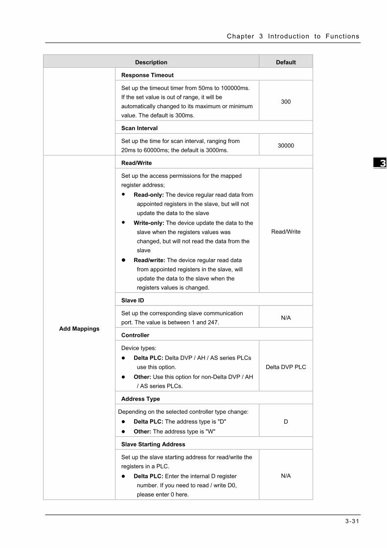
3.4.5 Modbus TCP This page is used for configuring the Modbus TCP, including Working Mode, Server IP, Server Port, and Response Timeout.

DX-3001 Series Industr ia l Cloud Router
3-30
_3
Description Default
Working Mode The default is OFF. Other options are:
Modbus TCP Server (Slave): for applications of a PLC to read/write the open registers in router. It supports up to 32 connections from client.
Modbus TCP Client (Master): for router to read/write the open registers in a PLC. It supports to connect to 4 different servers at most.
OFF
Modbus TCP Client
Server IP Set up the IP address of a PLC in the Modbus TCP Client mode N/A
Server Port Set up the server port of a PLC in the Modbus TCP Client mode 502
Chapter 3 Introduct ion to Funct ions
3-31
_3
Description Default
Response Timeout
Set up the timeout timer from 50ms to 100000ms. If the set value is out of range, it will be automatically changed to its maximum or minimum value. The default is 300ms.
300
Scan Interval
Set up the time for scan interval, ranging from 20ms to 60000ms; the default is 3000ms.
30000
Add Mappings
Read/Write
Set up the access permissions for the mapped register address;
Read-only: The device regular read data from appointed registers in the slave, but will not update the data to the slave
Write-only: The device update the data to the slave when the registers values was changed, but will not read the data from the slave
Read/write: The device regular read data from appointed registers in the slave, will update the data to the slave when the registers values is changed.
Read/Write
Slave ID
Set up the corresponding slave communication port. The value is between 1 and 247.
N/A
Controller
Device types:
Delta PLC: Delta DVP / AH / AS series PLCs use this option.
Other: Use this option for non-Delta DVP / AH / AS series PLCs.
Delta DVP PLC
Address Type
Depending on the selected controller type change:
Delta PLC: The address type is "D"
Other: The address type is "W"
D
Slave Starting Address
Set up the slave starting address for read/write the registers in a PLC.
Delta PLC: Enter the internal D register number. If you need to read / write D0, please enter 0 here.
N/A

DX-3001 Series Industr ia l Cloud Router
3-32
_3
Description Default
Other: Enter the hexadecimal actual address. For example: Holding Register: 400100, take 0100 (decimal) that is 64 (hex).
Supports the Holding Register : 400001~465535 (Decimal)
Device Starting Address
Set up the device starting address (decimal, input range is from $2048 to $4095). $ specifies that the match must start at the beginning of a Device Starting Address.
N/A
Length (1-123)
Here displays the number of the continuous address followed by the default mapped address.
N/A
Operation
Delete the selected mapped address. N/A
Add Mappings
Click the button to add mappings; the data mapping can be set to 200.
N/A
Edit Click to select the records from the mapped address to edit. N/A
Operation
The added mappings can be deleted here. N/A
3.4.6 Firmware Upgrade This page is used for upgrading the system.
Description Default
Select Firmware

Chapter 3 Introduct ion to Funct ions
3-33
_3
Description Default
Click “Browse” to select the new firmware file. N/A
Upgrade
Click “Upgrade” to upgrade firmware. The device will reboot after the upgrade is done.
N/A
3.4.7 Backup & Restore This page is used for backing up and restoring the configurations.
Description Default
Backup
Click “Backup” to save the device configurations on your computer. N/A
Restore
Click “Browse” to select the backup file and then click “Restore” to restore the configurations. The device configuration will be restored to the previous version and the device will reboot after the restoring is done.
N/A
Restore To Factory Default
Click “Restore To Factory Default” to reset the configurations to the factory defaults. The device will reboot after the reset is done.
N/A
3.4.8 System Reboot This page is used for manually rebooting the system. Click “Restart Device” and the system will reboot.

DX-3001 Series Industr ia l Cloud Router
3-34
_3
3.4.9 Scheduled Jobs This page is used for scheduling job configurations, including ADD A New Job, Export Job List, and Import Job List.
3.4.9.1 Add A New Job
Click “Add A New Job”, and then you will see the following page. Follow the instruction to add a new scheduled job.
Description Default
Job Name
Set up a name for your scheduled job. The name shall be composed of letters, numbers and underline, starting with a letter or number. The maximum string length is 32 bytes.
N/A
Enable
Select “Enable” to activate this functionality. Enable
Recurring Job
The scheduled job can be done Once, Every day, Every week, or Every month. And the specific time can be further defined.
Once
01:00
Date
Select a specific date to perform the scheduled job. 2015.01.01
Job Type

Chapter 3 Introduct ion to Funct ions
3-35
_3
Description Default
Select one of the job type for the scheduled job.
Restart device Enable DIACloud Service Disable DIACloud Service
Enable Cellular Network
Disable Cellular Network
Restart device
3.4.9.2 Export Job List
Click “Export Job List” to export the scheduled jobs for future usage.
3.4.9.3 Import Job List
Click “Chose file” to select the scheduled jobs file you have saved and then click “Import Job List” to import the
scheduled jobs you have set before.
3.4.10 Network Diagnosis This page is used for diagnosing the network status; methods are Ping Test and Route Trace.

DX-3001 Series Industr ia l Cloud Router
3-36
_3
Description Default
Diagnosing Method
Select the Diagnosing Method; options are Ping Test and Route Trace.
Ping Test
Host Name/IP Address
Select the domain name or IP address of the server that you want to test. The default options are www.google.com, www.yahoo.com, www.MSN.com, www.amazon.com, www.wikipedia.org, www.facebook.com, www.diacloudsolutions.com and others. When user choose others, user can input the domain/IP manual.
www.diacloudsolutions.com
Start
Click “Start” to start the network diagnosing. While running the network diagnosing, the settings cannot be changed.
N/A
3.4.11 Privilege Management Privilege management use in order to set the white list of phone numbers and the device operation can be triggered via the specific SMS text from the white list of phone numbers.
The SMS commands listed below:
Function SMS Command Description
SMS Query commands “ZLCX” or “zlcx” List all SMS commands and

Chapter 3 Introduct ion to Funct ions
3-37
_3
Function SMS Command Description
explanations.
Status Query “ZTCX” or “ztcx”
Discover the router's current status information, including the following:
1. Cellular network state 2. Firewall state 3. DIACloud state
Restart Device “CQLY” or “cqly” Restart the router
Enable cellular network “KQBH” or “kqbh” Dial-up the router to internet
Disable cellular network “DKBH” or “dkbh” The router disconnects from the internet
Enable DIA cloud service “KQVD” or “kqvd” DIA cloud service enables on the router
Disable DIA cloud service “GBVD” or “gbvd” DIA cloud service disables on the router
Currently, there are three the main SMS settings: 1. Short Message Control Gateway. 2. Short Message Controlling PLC.
3. Control List of Event Management. Setting interface as follows:

DX-3001 Series Industr ia l Cloud Router
3-38
_3
Description Default
Add A Telephone Number
ID
The maximum allow the 10 phone numbers N/A
Name
Set up a name for phone number, The name shall be composed of N/A

Chapter 3 Introduct ion to Funct ions
3-39
_3
Description Default
letters, numbers and underline, starting with a letter or number. The maximum string length is 32 bytes.
Telephone Number
Set up a telephone number (include country code) which can receive the alarm message.
N/A
Enabled
Set up the permission to enable or disable Yes
Short Message Reply
When the router receives the SMS commands, the router will response a confirmed message.
Yes
Set up an Email address to receive the alarm message. This setting work with The Event management.
N/A
Edit Edit the existing event N/A
Delete Delete the existing event N/A
Export The List Export the event of SMS Fixed_sms_control_list.cfg
Import A List Import the event of SMS to the router N/A
3.4.12 Event Management This page is used for setting up 3 types of events, Communication Verification, Alarm Event and SMS Queries Event.
Communication Verification: when this option is selected, the router will monitor and check if this channel is trustable to ensure a safe communication between a router and a PLC via MODBUS TCP, MODBUS ASCII or MODBUS RTU.
The operators that the expression supports are as below:
Operators Types Examples Description
+ Arithmetic operator A+100 Addition

DX-3001 Series Industr ia l Cloud Router
3-40
_3
- Arithmetic operator A-100 Subtraction
* Arithmetic operator A*100 Multiplication
/ Arithmetic operator A/100 Division
& Logic operator A&A+100 Logic AND
| Logic operator A|A+100 Logic OR
() Bracket operator (A+100)*45 Change operation order
^ XOR operation A^100 XOR operation
Alarm Event: uses can set up the Alarm Name, Alarm Description, Alarm Criteria, Target Receiver and Operation.
Click “Add” button to create new alarm event and click “Details” to edit the existing event and use ”Delete” button to delete the selected event. Click “Copy” to duplicate the event.

Chapter 3 Introduct ion to Funct ions
3-41
_3
Description Default
Alarm Name
Input an alarm name. The name shall be composed of numbers, English letters, uppercase and lowercase. The maximum string length is 32 bytes.
N/A
Alarm Description
The alarm description shall be composed of numbers, English letters, uppercase and lowercase. The maximum string length is 50 bytes.
N/A
Alarm Criteria
Setup the alarm trigger condition. The format of alarm variable is {$number 0-4095}, the alarm criteria can be a single alarm variable, or a formula of one or several alarm criteria. For example, the formula can be: {$2048}>100
N/A
Event Interval
The time interval of alarm sending 0
Repeat Times
The repeated times of alarm sending 0
Alarm Status
Enable or disable this alarm setting Enable
Alarm Content
Set up the information shown on the alarm contents. The content of the alarm will be sent to the target when alarm criteria are met. The information order can be self-defined.
N/A

DX-3001 Series Industr ia l Cloud Router
3-42
_3
Description Default
Time: the time when the alarm occurred Date: the date when the alarm occurred Name: the name of the occurred alarm Description: the description of the occurred alarm For example: Register $2048 represents electrical voltage, the value of register $2048 is 10, and the alarm content is set as: {Date} {Time} Voltage = {$2048}, then the alarm content received by users will be: 2016/06/01 10:00:00(currently time) Voltage = 10. The maximum content length is 160 characters.
Target Receiver
Set up the recipient. User can maintain the list by 【Control List Of Event Management】in Privilege Management function.
N/A
SMS Queries Event: user can declar a query event, when the mobile number in the Control List of event send a
query message, system will reply the special content to the mobile number.
Description Default
Query Name
Input a query name. The name shall be composed of numbers, English letters, N/A

Chapter 3 Introduct ion to Funct ions
3-43
_3
Description Default
and underline. The maximum string length is 9 characters. For example, after you create a query event name query1, you can send a message with content #MSG#query1 to device SIM card number, then it will reply you the content you setup in the event.
Query Description
The query description shall be composed of numbers, English letters, uppercase and lowercase. The maximum string length is 50 bytes.
N/A
Query Content
Set up the information shown on the alarm contents. The content of the alarm will be sent to the target when alarm criteria are met. The information order can be self-defined.
Time: the time when the alarm occurred Date: the date when the alarm occurred Name: the name of the occurred alarm Description: the description of the occurred alarm For example: Register $2048 represents electrical voltage, the value of register $2048 is 10, and the query content is set as: {Date} {Time} Voltage = {$2048}, then the query content received by users will be: 2016/06/01 10:00:00(currently time) Voltage = 10. The maximum content length is 95 characters.
N/A
Target Receiver
Set up the recipient. User can maintain the list by 【Control List Of Event Management】in Privilege Management function. System only response the query from receiver list.
N/A
Notice {} is a special system symbol, which is used to reference system variables or system registers, like ${Time}, ${Date} or ${Number 0 - 4095}. Please use it with caution.
3.4.13 Register Management This page is used for setting up the rules of register data upload to Cloud. Click “Add” to set a new rule. Click ”Edit” to modify the existing rule. Click “Delete” to delete the existing rule.
The address segment 2048~4095 can be self-defined. The Start address, Length, Uploaded to Cloud or not and keep history or not can be set up.. After clicking “Add”, the following page will show up.

DX-3001 Series Industr ia l Cloud Router
3-44
_3
Description Default
Register Start Address
This rule will effect from which register address. The allowable range is 2048~4095. Start with $.
N/A
Length
How many register will be effect by this rule. Input range: 1-2048. N/A
Uploaded To Cloud
Whether to upload the variable information to Cloud. Yes
Keep History
This function will keep or overwrite the history data when the register values are uploaded to Cloud.
Yes: The existed register values in the cloud WON’T be overwritten by the new uploaded register values.
No: The existed register values in the cloud CAN be overwritten by the new uploaded register values.
No
Notice When the values in the register changes, the results will be uploaded to cloud.
3.5 Cloud Service 3.5.1 Cloud Service In this page, user can assign the cloud account which will be used to connect to DIACloud by device. Input the user name, the password and click “Verify”. Refer to Chapter 4 for DIACloud account registration.
1. Login with your DIACloud account then click the “Verify” button to authenticate with DIACloud server.

Chapter 3 Introduct ion to Funct ions
3-45
_3
2. After authentication successfully, the cloud configurations will show up then the user can modify the secure tunnel
and device name.
3. The user also can set IP address manually.
4. Click the "Bind" button, the DX router will bind with DIACloud server and established a secure tunnel between
DIACloud server and the DX router. Meanwhile a new IP will assigns to DX router from DIACloud server (assign from the cloud HDCP server or a user specified).

DX-3001 Series Industr ia l Cloud Router
3-46
_3
5. Your browser will access to the DX router with new IP address automatically if DIACloud account binds with DIACloud server successfully. Please make sure a PC and DX router are in the same subnet; otherwise PC will not be able to access to the DX router.
6. If the network is in the poor condition, The binding proccess could be successfully but the Service Status is shown
“Disable”.
7. In this situation, the browser will access with 192.168.1.1 and the service status will be “Disable”. You can re-enable the service status to rebuild the secure tunnel again in cloud configurations.

Chapter 3 Introduct ion to Funct ions
3-47
_3
8. When the service status is shown “Enable”, that means the DIACloud service is actived on DX-3001H9. The user also can get the related information in cloud platform.
9. Click the “Unbind” button, DX-300H9 will remove the registered account in DIACloud.
Description Default
User Name
Set up the name for the DIACloud account. N/A
Password
Set up the password for the account. N/A
Verify
Check if the username and the password are matched. N/A
Secure Tunnel
Select the device under the account to join in a certain secure tunnel network group. For secure tunnel related settings, go to http://www.DIACloudsolutions.com/
Default
Device Name
Set up the name for the device N/A
Secure Tunnel DHCP
When secure tunnel DHCP server is available, and the IP address is allocated by the DHCP server in secure tunnel network, the IP address of this device can be found in the cloud portal.
N/A
Get IP From Cloud
When selecting “Yes”, IP address can be obtained by the cloud. When selecting “No”, the IP address can be manually set.
Yes
Network protocol

DX-3001 Series Industr ia l Cloud Router
3-48
_3
Description Default
Set up the network protocol for Secure Tunnel. Options are TCP and UDP. Suggest use TCP when the network packet loss is serious. Only TCP is available when proxy function was enable. User can change it yet after device has been bind the cloud account. Please disable the service first and then you can change the protocol, and remember to enable the service again.
UDP
Cloud IP Range
Display the Cloud IP Range. The Cloud IP Range is depended on the secure tunnel setting. For the secure tunnel setting, please refer to 5.2.5 Tunnel Network.
N/A
Cloud Netmask
Display the Cloud Netmask. The Cloud Netmask is depended on the secure tunnel setting. For the secure tunnel setting, please refer to 5.2.5 Tunnel Network.
N/A
Device IP
User can assign an IP address manually; remember that IP address should be the same subnet as the secure tunnel setting. For the secure tunnel setting, please refer to 5.2.5 Tunnel Network.
N/A
Notice Users can log-in to http://www.DIACloudSolutions.com/ and register for a
DIACloud account.
In rare case, you can’t access the web because the computer did not refresh the IP and DNS after the activation, please re-plug the cable to resolve the issue.

Chapter 3 Introduct ion to Funct ions
3-49
_3
3.5.2 Proxy Setting If the user’s networking environment requires outbound network connections to go through a HTTP or HTTPS proxy.
Description Default
HTTP Proxy
Enable or disable the http proxy Disable
Proxy Addr
Set up the domain/IP of the proxy server N/A
Proxy Port
Set up the port of the proxy server N/A
Proxy Username
Set up the user name to login the proxy server N/A
Proxy Password
Set up the password to login the proxy server. N/A
Save and Test
Save the configuration and test to connect to the DIACloud. N/A

DX-3001 Series Industr ia l Cloud Router
3-50
_3
3.5.3 Secure Tunnel Firewall In this page, user can set up the firewall for the secure tunnel.
Description Default
Allow multicast in secure tunnel
Set the security tunnel, whether to allow multicast transmission of the nature of the packet.
Options: Allowed, not allowed Yes
Firewall of secure tunnel
Set up the specified MAC device will be allow or forbid to transmit the data in the secure tunnel. Options as below:
Disable: Disable this function.
Black List: If the network device's MAC address is blacklisted, these devices will NOT be able to transmit packets to the secure tunnel
White List: If the network device's MAC address is blacklisted, these devices will be able to transmit packets to the secure tunnel.
Disable
Add
Add a new MAC into the list. N/A

Chapter 3 Introduct ion to Funct ions
3-51
_3
3.5.4 Cloud Log Any information about cloud event can be exported from this function
Description Default Cloud Log Level
You can set different levels of log messages and saved to export to the engineering staff to view. Options as below (Level from low to high):
Trace: The TRACE Level designates finer-grained informational events than the DEBUG
Debug: Fine-grained informational events that are most useful to debug an application
Info: The INFO level designates informational messages that highlight the progress of the application at coarse-grained level.
Warm: The WARN level designates potentially harmful situations.
Error: The ERROR level designates error events that might still allow the application to continue running.
Fatal: The FATAL level designates very severe error events that will presumably lead the application to abort.
Error
Select Log Level Specify to download the cloud service module log. Options as below:
Uploader: Data upload module
Secure Tunnel: Secure Tunnel module
Binding: Account binding module
Uploader

4-1
Chapter 4 DIACom
Table of Contents
4.1 Introduction to DIACom ............................................................................. 4-2 4.1.1 Select a Suitable Firmware Version .......................................................... 4-2 4.1.2 DIACom Installation ............................................................................... 4-3 4.1.3 DIACloud Account Registration ................................................................ 4-3 4.1.4 Bind DIACloud Account ........................................................................... 4-5
4.2 DIACom Operation ..................................................................................... 4-6 4.2.1 Setup a Secure Tunnel ........................................................................... 4-6 4.2.2 Create a Virtual Serial-port ................................................................... 4-11 4.2.3 Remote Control and Monitoring via DIACom ............................................ 4-12 4.2.4 Automation Startup ............................................................................. 4-14
4

DX-3001 Series Industr ia l Cloud Router
4-2
_4
4.1 Introduction to DIACom DIACom allows you to create a secure tunnel between your PC and router, making it possible for your PC to communicate remotely with the devices connected to the router. Thus engineers can control, monitor, operate, program and diagnose the device remotely whenever there is internet connectivity.
Notice DIACloud provides you with cloud services, including the connected device
management, secure tunnel network creation, data upload/download, and directional transmission.
If you need to configure or monitor your controller, you will need to install programmable logic controller software, for example WPLSoft/ISPSoft for Delta PLC.
4.1.1 Select a Suitable Firmware Version Find a suitable DIACom firmware version according to the following table below for your router.
Corresponding Table:
Device Model Firmware Version DX-2100 V1.3.3.0 or above DX-2300 V1.3.3.0 or above DX-3001 V1.3.3.0 or above
Notice If the device firmware is lower than 1.3.3.0, please use DIACom 1.2.8.0 or lower.

Chapter 4 Introduct ion to DIACom
4-3
4_
4.1.2 DIACom Installation Obtain the DIACom firmware package from the official website or from our sales representative. Administrator privileges are required to run and install the package. Uninstall older versions of DIACom before downloading new DIACom firmware package.
Notice DIACom supports Windows XP, Windows 7 (32-bit and 64-bit) and Windows 8 (32-bit and 64-bit).
4.1.3 DIACloud Account Registration 1. Before registration, you should have a valid email account. (DIACloud uses your email
address as your account.)
2. Open the DIACloud web page (http://www.DIACloudSolutions.com). The system will redirect you to the registration page:
Notice *Click at the upper right corner to change the interface language to English.
3. Input your email address, password and other relevant information on the registration page. Select “I Agree” and click “CREATE AN ACCOUNT”.

DX-3001 Series Industr ia l Cloud Router
4-4
_4
4. After clicking “CREATE AN ACCOUNT”, a congratulation page will be prompted and an activation email will be sent to the email address you have used as your DIACloud account.
5. You will find an activation email sent from [email protected] in your email box. Open the email, click “here” link in the email and complete DIACloud account activation operation. And you will be redirected to the DIACloud login page. Input your account and password to log in to the DIACloud.

Chapter 4 Introduct ion to DIACom
4-5
4_
4.1.4 Bind DIACloud Account Follow the steps blow to bind your DIACloud Account.
1. Local Network Setups: Please refer to Chapter 2.1 to 2.1.3 Web-based GUI Configuration for more information.
2. Bind DIACloud Account: Please refer to Chapter 3.5 Cloud Service for more information.
Notice Secure Tunnel: Secure tunnel is a virtual network. Users can set up several
groups of secure tunnel for easier device management. Device Name: the serial number + “_” + “Mac address” of the device is the device
name by default.
Get IP From Cloud:
When selecting “Yes”: The system will assign an IP address for the device according to the Secure Tunnel settings and the availability of the IP addresses. Take note of the assigned IP address, it will be used when logging to the DIACloud.
When selecting “No”: The IP address can be manually set.
The IP address of the DX-2100 Series and the WAN of your connected PC should be in different network segments.

DX-3001 Series Industr ia l Cloud Router
4-6
_4
4.2 DIACom Operation 4.2.1 Setup a Secure Tunnel Make sure there is internet connectivity, before creating a secure tunnel between your local PC and router via the DIACom. Http Proxy and Port Agent are configurable in DIACom network setting function, you can set it to avoid the possible limitation.
1. Run DIACom and log in with your router’s cloud account.
2. Click to go into network setting page if need be.
Http proxy: Please fill in the proxy server address, port, username and password if the LAN needs to set the proxy to access the Internet. Click “Save” button to enable the config.
Diagnose: The user can click the Diagnostic button to test the current internet settings, whether to connect to the DIACloud server

Chapter 4 Introduct ion to DIACom
4-7
4_
Notice DIACom will automatically determine whether the port agent
needs to enable.
Make sure that the external network port 80 and port 443 are opened and can access any network domains and IP addresses
3. After the login is successful, the software displays the security tunnel page. The security tunnel list is displayed on the left side of the page, and the network information of the security tunnel and the device list are displayed on the right. Users can choose to use DHCP or manually set the cloud IP address
DHCP: Obtain an IP address from Cloud automatically when Cloud DHCP function is available.
Static: Manually set the IP address, the IP should be in the same subnet with DX device

DX-3001 Series Industr ia l Cloud Router
4-8
_4
Notice If it is found that the static IP address is configured from DIACom, the IP address of the local IP address in the bottom right corner will be different from the original setting. Please change according to the following settings.
1. Go to Network and Sharing Center and click on the DIACom Ethernet Adapter for your network connection.
2. Right-click, then click Properties.
3. Click the Networking tab. Under This connection uses the following items, click either Internet Protocol Version 4 (TCP/IPv4)。
4. Set the IP address of the local computer manually. However, you’ll need to make sure there are no IP conflicts.

Chapter 4 Introduct ion to DIACom
4-9
4_
4. After the configuration is complete, click the Create Tunnel button to establish a connection with the specified tunnel.
5. The following information is displayed: tunnel connection status, local delay to the DIACloud cloud server, and the IP address used by the local virtual network adapter. The details are as follows:
6. After successful connection with the cloud, the local computer will be able to use debugging tools or monitoring software to debug, monitor, and program the remote network interface

DX-3001 Series Industr ia l Cloud Router
4-10
_4
devices. In addition, you can remotely configure the router's router page (click the device in the device list Of the IP address) of the router for remote configuration.
Notice
You can create different groups of secure tunnels, divide different devices into groups according to their needs, and implement group management devices
To avoid the virtual network card IP network segment and the local computer network card of the actual network to avoid the same network conflict
After the secure tunnel is successfully connected, you must first disconnect the current connection to select another security tunnel,

Chapter 4 Introduct ion to DIACom
4-11
4_
4.2.2 Create a Virtual Serial-port To debug a remote serial device, click the icon at the back of the corresponding remote device to enter the Create Virtual Serial Interface
The latest device firmware (V1.3.3) supports RS-232 and RS-485 at the same time in the transparent mode, the interface as shown below:
Notice
If the device's RS-232 / RS-485 is not operating in Transparent mode, the corresponding button is grayed out.
DIACom will prompt an error message if the FW version of DX is under V1.3.3.

DX-3001 Series Industr ia l Cloud Router
4-12
_4
When RS-232 or RS-485 works in Transparent mode, click on the [Create Serial Port] button on RS-485 to create a virtual serial port.
4.2.3 Remote Control and Monitoring via DIACom 4.2.3.1 Via a LAN Port
If your router is connected to remote devices via a LAN port, you can use the configuring/monitoring software on your local computer to configure and monitor after opening a virtual tunnel. Some program would require the IP addresses of your remote device. Simply input the required information in the configuring/monitoring software and then you can configure and monitor the connected device remotely.
4.2.3.2 Via a RS232/RS485 Port
After opening a virtual tunnel, you will need to follow the setups below before using WPLSoft or other configuring/monitoring software on your local computer to configure and monitor the connected device remotely.
1. Click IP address in the DIACom device list or open a browser and input the IP address of the
router which is connected to your remote device on the search bar and then log in.
2. Go to the System setup page, select the setup option RS232 or RS485 and input the required information to set up. Make sure the parameters are consistent with your remote device.
Working Mode:Transparent mode
Parameters of COM (Baud Rate, Data Bits, Stop Bits, Parity Bits, Flow Control)
3. Go back to the DIACom and click to create a virtual tunnel. Once the creation is done, the virtual serial-port number will show up on the same page. Users can use it to configure and monitor the connected device remotely. Click “Delete” to delete the virtual serial-port.

Chapter 4 Introduct ion to DIACom
4-13
4_
Notice If the PLC is Siemens S7-200, you can select the “PPI” in the DIACom to support PPI protocol.
4. Open the WPLSoft to check if the COM parameters are consistent with the settings on your router. When these parameters are consistent, you can use the WPLSoft to configure/monitor your device remotely.

DX-3001 Series Industr ia l Cloud Router
4-14
_4
4.2.4 Automation Startup The user can set Automation Startup for DIACOM, The setting steps see blow.
1. Login to DIACom.
2. Click on the icon button in the upper right corner of the windows, and select "Settings".
3. Boot automatically log in the required configuration is as follows. Users can set according to your needs. If you only need DIACom to connect the security tunnel automatically, the device list, RS-485 and RS-232 do not need to be set.
4. Check " Start DIACom on windows logon ", and click "OK" button to save the settings.
Notice
Login must be checked "remember password", otherwise DIACom can not be activated automatically
Confirm that the IP / Serial Port settings do not cause conflicts

5-1
Chapter 5 DIACloud
Table of Contents
5.1 Introduction to DIACloud .............................................................................. 5-2 5.1.1 Select a Suitable Firmware Version .............................................................. 5-2
5.2 Instructions for DIACloud .............................................................................. 5-2 5.2.1 Register and Login .................................................................................... 5-2 5.2.2 Home ...................................................................................................... 5-4 5.2.3 Devices ................................................................................................... 5-6 5.2.4 Alarm .................................................................................................... 5-16 5.2.5 Secure Tunnels ....................................................................................... 5-17 5.2.6 Sub Users .............................................................................................. 5-19 5.2.7 Logs ..................................................................................................... 5-22 5.2.8 Orders................................................................................................... 5-23 5.2.9 Profile ................................................................................................... 5-24
5

DX-3001 Series Industr ia l Cloud Router
5-2
_5
5.1 Introduction to DIACloud DIACloud Web is a web portal of DIACloud cloud platform. Users can check the status of connected industrial device through DIACloud Web, browse data that has been collected, receive warnings, notices and other messages that are sent by cloud platform, create and manage sub-account and virtual safety network and check login and interface logging, to improve the manageability of devices, optimize the device performance and efficiency, save the operation cost and enhance the service quality.
5.1.1 Select a Suitable Firmware Version Please confirm that your Firmware version of router meets the requirements in the following table before use:
Device Model Firmware Version DX-2100 V1.3.0.0 or above DX-2300 V1.0.0.0 or above DX-3001 V1.3.0.0 or above
5.2 Instructions for DIACloud 5.2.1 Register and Login 1. Open the DIACloud web page (http://www.DIACloudSolutions.com). If you have got an account, input your account
and password in the following page to log in; if you have not got an account, click “CREAT AN COUNT” to register. Then the system will redirect you to the registration page:
2. Input your email address, password and other relevant information on the registration page. Select “I Agree” and click “CREATE AN ACCOUNT”. Pls insure your region information is correct, otherwise it maybe cause problem in payment when you extend your service.
Notice Click at the upper right corner to change the interface language to English or Chinese.

CH5 Introduct ion to IOT DIACloud
5-3
_5
3. After clicking “CREATE AN ACCOUNT”, a congratulation page will be prompted and an activation email will be sent
to the email address you have used as your DIACloud account.
4. You will find an activation email sent from [email protected] in your email box. Open the email, click “here” link in the email and complete DIACloud account activation operation. And you will be redirected to the DIACloud login page. Input your account and password to log in to the DIACloud.

DX-3001 Series Industr ia l Cloud Router
5-4
_5
5. Open the DIACloud web page (http://www.DIACloudSolutions.com). Log in using your account that you have registered.
5.2.2 Home The Home Page will show up after login.

CH5 Introduct ion to IOT DIACloud
5-5
_5
Item Description
Menu User can switch to corresponding function through menu on the left.
Devices Total The number of total devices
Devices is Online The number of total online devices
Alarms in 24 Hours The number of alarms in Recently 24 hours
Secure Tunnel is Usable It will show the number of Secure Tunnel groups under the account.
Switching among the Chinese and English
Show the service package you selected, user can add packeage to shopping cart through Devices function and Profile function.
Show the alarm message(s) in latest 7 days
Show the profile or logout
Online payment process as below:
1. After click , it will show the detail information in shopping cart.
2. Click to generate an order. DIACloud provides the follow types of invoices.
No need For Invoice
Electric Invoice
Paper Invoice

DX-3001 Series Industr ia l Cloud Router
5-6
_5
3. Click , we accept PayPal payments and process credit cards on your order forms.
5.2.3 Devices It will switch to page of device list after clicking “Devices” in navigation bar.
Item Description
You can filter the device base on you input the key word of the device name.

CH5 Introduct ion to IOT DIACloud
5-7
_5
Filter base on tunnel group, show all devices or only show the devices under user specified tunnel group.
Devices List
Show the list of device.The information include device’s name, device’s SN, device’s type, storage usage, data usage, the time of binding device. Green represents that the device is on-line Gray represents the device is off-line.
: Represents that all device is displayed currently, and you can switch to on-line device list after clicking this icon.
: Represents that on-line device is displayed currently, and you can switch to list of on-line device after clicking this icon.
Show relevant position information of device.
Refresh pages
Show detail information of the device
: It will show relevant position information of device after you click “ ” , which is shown as follows:
It will show the device name and SN of the device after clicking position icon in the map. When there is large number of device of user, it will switch to corresponding device when user clicks blue arrows at the edge of the map.
: More detail information about device will be shown after clicking under the “Operation” at the
most right side of device list:
1. OVERVIEW: The page will show the basic information of the device and latest alarm message.

DX-3001 Series Industr ia l Cloud Router
5-8
_5
Item Description
Operation zone of device
It represents that device is on-line if background color is blue, and device is off-line if it is gray.
: Show device names; it can switch device after clicking the drop down arrow.
: Realize refresh of device data on operation page.
: Close the operation page.
Page switching
Operation is divided into 4 pages:
Overview
Registers
Package
More Different buttons are used to switch different pagers.
Basic information zone
Basic information is shown in Overview page.
IP Address: it means the IP that has been bound for device;
Tunnel Network: it means virtual network that has been bound to device;
Boot Time: it means the boot time of device;
RS232 Mode: work modes of RS232, including transparent transmission mode and slave station mode;
RS485 Mode: work modes of RS 485, including transparent transmission mode, slave station mode and master station mode;
Modbus TCP: work modes of Modbus TCP, including Modbus TCP Server,Modbus TCP Client and Closed

CH5 Introduct ion to IOT DIACloud
5-9
_5
RSSI: it means signal strength of device which contains 5 bars; the larger the number of green bars is, the stronger the signal strength is;
Latest Alarms
The latest five Alarm of the current device. “ ” represents the state that the email is being sent;
Green represents that the email has been sent successfully
Red represents failure of sending.
2. REGISTER: The page will show and manage register value that uploaded from DX production.
Item Description
The filtering function displays a list of keywords that match specific register.
Click and add the corresponding register and register value, then click “SAVE” button. DIACloud server will send the corresponding data to the device.
“<” Pervious page,“>” Next page,“1/205” show the current page of register table and the total amount of register table page.
Register Table Show the register table, registers show a maximum of 10 posts per page.
Register Name Show the register name, when you do not make an alias configuration in the register, the register number is displayed; an alias configuration in the register will be displayed after you configure the alias
Register Value Show the current register value and data transfer time. For the double word or float type data, please refer to the ‘Config’ function.

DX-3001 Series Industr ia l Cloud Router
5-10
_5
You can view the current register of historical data or delete the current register; it can also be configured to register. P.S. If this register is not set to remeber history (device configuration page), the menu
does not appear [History] after clicking icon.
The History and Config options will be shown after clicking
Item Description
History It represents trend chart of historical data
Delete User can delete the all data of this register
Config User can customize name of register and content returned.
History : The following figure will be shown after clicking “History”:

CH5 Introduct ion to IOT DIACloud
5-11
_5
Item Description
Date Start Set the Date Stare and query the historical data for a specific time
Date End Set the Date End and query the historical data for a specific time
Register Value History Diagram The latest trend chart of value of register;
Time Axis User can change time scope of historical data by sliding “ ”.
Export the data to CSV.file.
Config : The following information will be shown after clicking “Config”

DX-3001 Series Industr ia l Cloud Router
5-12
_5
Item Description
Length
Length can be set to Word, DWord and Float.
DWord: DWord needs to use two DX internal registers. For example: $2050 and $2051 are set to DWord and it will combin to $2050, $2050 will be LOW Byte and $2051 will be HIGH Byte.
Float: Float needs to use two DX internal registers. For
example: $2050 and $2051 are set to DWord and it will combin to $2050, $2050 will be LOW Byte and $2051 will be HIGH Byte.
Alias Name The user can set the name of the register to be displayed in the "Alias Name"
function(val) function(val) is used for convert the register value, and the grammar of function-supported JavaScript is similar.
There are two examples for “function (val)”. Example 1 : If you want to show the wind speed as 10m/s. (Data +unit, such as: speed 10m/s).
Input the code: return val+“m/s” in function (val){…} as the following picture.
Save the configuration. Example 2: If you want to convert the register value to the text such as the register value of 1 shows the text as ‘NO’;
register value of 2 shows the text as ‘OFF’
Input the code in function (val) {…} as the following picture.

CH5 Introduct ion to IOT DIACloud
5-13
_5
Save the configuration.
3. SERVICES: This page shows the Device Data Usage, Device Storage Usage and Account Storage Usage for users.
Item Description

DX-3001 Series Industr ia l Cloud Router
5-14
_5
Data
Device Data Usage: Show device traffic usage till now and total capacity.
Account Traffic Usage:
1. Account traffic is the total amount of traffic showing additional purchases.
2. Account traffic can be shared with all devices under your account.
3. Before the device traffic is exhausted clould traffic, the account traffic will not be used.
: User can purchase more traffic package for this accoount if need. After successful payment, the moment is ready for use.
: Show the Data Usage History in past 12 months.
Storage
Device Storage Usage: Show device storage usage till now and total capacity
Account Storage Usage:
1. Account storage is the total amount of traffic showing additional purchases.
2. Account storage can be shared with all devices under your account.
3. Before the device storage is exhausted strorage space, the account storage will not be used.
: User can purchase more traffic package for this accoount if need. After successful payment, the moment is ready for use.
After Click the in Data field, it will show the traffic package select page. User can add a package to cart or pay it direct.
After Click the , it will show the Data Usage History in past 12 months.

CH5 Introduct ion to IOT DIACloud
5-15
_5
After Click the in Storage field, it will show the storage package select page. User can add a package to cart or pay it direct.
4. MORE: This page will show the Serial Number, Software Version, Hardware Version, and IMEI for users.

DX-3001 Series Industr ia l Cloud Router
5-16
_5
Item Description
Serial Number Serial number of device
Software Version Version information of software
Hardware Version Version information of hardware
IMSI International Mobile Subscriber Identification Number.
Delete binding relationship between device and the account. Device needs to be un-bund after clicking this button, and user can recover the device by rebinding.
5.2.4 Alarm Click the Alarm in the left menu. The warning information in the latest 7 days will be shown in this page. The warning information includes name and serial number of device, content of warning, status of email that is being sent (green“ ” represents that the email has been sent successfully, and red represents fail.), time of warning and content record of warning.

CH5 Introduct ion to IOT DIACloud
5-17
_5
5.2.5 Secure Tunnels Secure Tunnel is an important concept in DIACloud. Its objective is to realize virtual Switch across Internet; when device is bound to this network, it will be equivalent to adding device with one LAN port; when PC operates DIACom and creates a virtual network, PC and the device will be under the same switch at this time. It is shown as follows

DX-3001 Series Industr ia l Cloud Router
5-18
_5
Users can manager the tunnel network in this page. Interface is shown as follows:
tem Description
Search the existed tunnel network
Tunnel network List List all tunnel network under this account
Add a new tunnel network
Refresh the tunnel network list
Edit the tunnel network
Item Description
Tunnel Network Information
The detail information of tunnel network:
Network Name: User can enter a name of tunnel network.
DHCP Option: Automatic IP Address Assignment by DIACloud.
DHCP IP Start: it represents the beginning IP in automatic IP distribution address pool of DIACloud
DHCP IP End: it represents the ending IP in automatic IP distribution address pool of DIACloud.

CH5 Introduct ion to IOT DIACloud
5-19
_5
If the DHCP of thes tunnel network is enabled, click will export configurations include DIACloud Servier /account /Tunnel networks info to a file (default file name Provision_vlnname_date_time.bin).
DX-3001H9 DOES NOT support this function.
Delete the current tunnel network
Close the current operation window.
Save the configuration of tunnel network
5.2.6 Sub Users All accounts that are registered through register page of DIACloud (http://www.DIACloudSolutionscom/#/signup) are main accounts. Every main account can create sub-account, and users can realize power separation and grouping management of device by conducting authorization for virtual network and DIACom by sub-account. Use can conduct addition and operation for sub-account through the “Sub Users” page.
Item Description
Search the sub users.
Sub Users List Show the list of all sub users in main account.
Add a sub user.
Refresh the list of sub users.
Modify the access control of the tunnel network.
: User can modify the access control of the tunnel network.

DX-3001 Series Industr ia l Cloud Router
5-20
_5
Item Description
Sub Users Information
Edit register: Allow the Sub User to modify register
Login to DIACom: Allow the sub user to access the DIACom if the option is enabled.
Tunnel Network: Allow the sub user to access the Tunnel Network if the option of Tunnel Network is checked.
Delete a sub user.
Close the current operation window.
: User can add sub users after clicking the “+” in the page, and. The following interface will be shown after clicking the “+” in the page:

CH5 Introduct ion to IOT DIACloud
5-21
_5
1. Fill in corresponding account information and conduct authorization for it.
2. The system will send an activation email which is attached with random login password to email box of sub user. The account status is “Un-activated” now.
3. Goto the mailbox, click the hyperlink to complete account activation operation, then sub user can login DIACloud with new account.
4. The page will link to the following page after clicking the activation link in the email:

DX-3001 Series Industr ia l Cloud Router
5-22
_5
5. When user login to DIACloud with main account and the sub user that we created has been activated.
5.2.7 Logs This page will show the web operation information of some users. It includes: login IP, setup of register, API interface call of DIACloud and other information.

CH5 Introduct ion to IOT DIACloud
5-23
_5
5.2.8 Orders In this page, user can check his all orders. Continue to pay for the unpaid orders or cancel the unpaid orders.
Item Description
View the order detail information
Pay for the unpaid order
Cancel the order, order will remove from the list.
Order detail
Payment Method: Currently, we only support PayPal payment for the world wide user.

DX-3001 Series Industr ia l Cloud Router
5-24
_5
5.2.9 Profile In this page, QR Code of user, Package info, password management and other information will be shown.
Item Description
QR Code You can get the part information of user by using DIACloud APP and scanning QR Code.
Account The current account information.
Packeage info
Show account traffic/storage usage till now
user can purchase more traffic/storage package for this account if need
Account traffic/storage will share to all devices under this account.traffic/storage will share to all devices under this account.
Change Password
Change the password of DIACloud user account.
Parts of old users use password in 6 digits; the new password has been increased to 8 digits to improve safety of their accounts.
Change Password page as below

CH5 Introduct ion to IOT DIACloud
5-25
_5

6-1
Chapter 6 DIACloud APP
Table of Contents
6.1 Introduction to DIACloud APP .................................................................... 6-2 6.1.1 Select a Suitable Firmware Version .......................................................... 6-2 6.1.2 DIACloud APP Installation ....................................................................... 6-2
6.2 DIACloud APP Function .............................................................................. 6-3 6.2.1 DIACloud APP Login ............................................................................... 6-3 6.2.2 Device List ............................................................................................ 6-4 6.2.3 Device Details ....................................................................................... 6-5 6.2.4 Registers View ...................................................................................... 6-6 6.2.5 Alarm List ............................................................................................. 6-7
6

DX-3001 Series Industr ia l Cloud Router
6-2
_6
6.1 Introduction to DIACloud APP DIACloud APP is the client software of DIACloud cloud platform running on mobile devices. The APP supports both iOS and Android mobile system, it enables users to view the field data collected, the locations of the field devices, and the alarms/notifications pushed by the industrial IOT cloud platform, so that keep users posted anytime and anywhere, and therefore improve the manageability of devices, optimize the device performance and efficiency, save the operation cost and enhance the service quality.
6.1.1 Select a Suitable Firmware Version The APP can support the devices below:
Device Model Firmware Version DX-2100 V1.3.0.0 or above DX-2300 V1.0.0.0 or above DX-3001 V1.3.0.0 or above
6.1.2 DIACloud APP Installation The DIACloud APP is available on Google Play and Apple APP Store.
Mobile Device OS Version Android 4.4.0 or above iPhone 6.2.0 or above

Chapter 6 Introduct ion to DIACloud APP
6-3
6_
6.2 DIACloud APP Function 6.2.1 DIACloud APP Login Enter the DIACloud account and password, then click the “Sign in” button to login the APP. Click the “Sign up” to register an account if you don’t have one.
Item Description
Scan QR code, the QR code is generated by DIACloud Web portal, which carries the user name and password information. By scanning the QR code, user won’t need to input user name. By default, the APP will connect the default DIACloud server in the cloud, if the APP is to connect other servers, QR code should be scanned to provision the APP.
DIACloud account, Email format
The password of DIACloud account, click to see what are you input
Auto Login Save the password and login the APP automatically
Login Login to App
Sign up Create a new DIACloud account
Forget Reset the password if you forget it.
Switch the language.

DX-3001 Series Industr ia l Cloud Router
6-4
_6
6.2.2 Device List Device list will be shown after user login the APP.
Device tab and alarm tab will be shown in the APP. In the device tab, the device information will be shown, include the value of registers of the remote device. And the value of the register can be changed in the APP as well. In the alarm tab, users can read the alarm messages.
Item Description
Logoff or exit App
Search Search device base on key word
All/Online Click “ALL” to show all device Click “Online” only show online device. Digit at the back is the
all/online device count.
Device list Display device online/offline status, device name, device serial number. Click it will go into device detail page
Switch to device list page
Switch to alarm list page.

Chapter 6 Introduct ion to DIACloud APP
6-5
6_
6.2.3 Device Details Device details will be shown by selecting a device in the device list.
Item Description
Type Type of the device
Time The time when the device is online.
IP IP Address of the device
Account DIACloud account activating the device.
Mode
The working mode of RS485 and RS232..
RS232: Transparent transmission mode or Slave mode
RS485: Transparent transmission mode / Slave mode / Master mode
Map Showing the location of the device on the map P.S. DX-2300 Series doesn’t support this function.

DX-3001 Series Industr ia l Cloud Router
6-6
_6
6.2.4 Registers View Click [Register] on the device details page to switch to the register page
In the register page, the user can browse the collected data. The register data can be refreshed by the pull-down screen. When the number of registers is large, you can pull up the screen to display more data.
Item Description
Refresh the register data.
Edit the register value.

Chapter 6 Introduct ion to DIACloud APP
6-7
6_
Click “ok” button, the register value will be pushed to the device.
6.2.5 Alarm List Alarm criteria can be set on the device configuration web page. When the alarm criteria are met, the device will send out alarm messages. User can click the “Alarm” tab to read the alarm messages. When there are new alarm messages, the number of the unread messages will be shown on the icon .
Alarm tab will be shown by clicking icon , the alarm messages in Red are unread messages. Digit in parentheses is the number of alarm messages.
Pull down the APP to refresh the alarm list.

DX-3001 Series Industr ia l Cloud Router
6-8
_6


![NFI – INDUSTRIAL AUTOMATION TRAINING ACADEMYnfiautomation.org/Six Months Industrial Automation Syllabus.pdf · [NFI – INDUSTRIAL AUTOMATION TRAINING ACADEMY] ... Motor Timing](https://img.pdfslide.net/doc/110x75/5af8aad47f8b9ad2208cd6bd/nfi-industrial-automation-training-months-industrial-automation-syllabuspdfnfi.jpg)