Embed Size (px)
Citation preview

FIBER OPTICS INDUSTRIAL E
Industrial fiber optic componentsand LED solutions
Lighting, Sensing, Imaging
SCHOTT_04141_Industrietech7.qxd 24.09.2004 12:46 Uhr Seite 1

32
New fiber optic compontents for widely
differing industrial applications are the
outcome of very close cooperation with
our customers. Customer ideas gener-
ated from knowledge of their product
and their industry coupled with
SCHOTT’s fiber optic know-how result
in new products with clear benefits to
the market.
The Fiber Optics Business Segment offers high-tech solutions in markets such
as automotive, lighting, medical, industrial and defense.
By mastering glass, fibers and processes for the production of fiber optic
components, we develop outstanding, market-oriented products. With our
leading technological know-how and innovative ideas we contribute to the
success of our customers – around the world, around the clock.
Generations of know-how as clear as glass
Creative new solutions
We will continue to carry out further research and development in the future
to continuously improve our products. We can be your single source fiber
optic specialist to support development stages from basic research and proto-
typing to mass production with competent quality, creativity and support.
The earlier we are involved in your project, the more effectively we can help
to develop optimum solutions for your special requirement.
We are continuously striving to develop new technologies: latest develop-
ments include LEDs (Light Emitting Diodes) for illumination components.
Content
2–3 | Introduction
4–5 | Physical principles and properties of optical fibers
6–13 | Manufacturing/Design of light guides
14–15 | Physical principles of LEDs
16–17 | Manufacturing/Design of image guides
18–23 | Applications
We work in partnership with you to develop new products:
For more than 40 years, SCHOTT has
developed fiber optic products for a
diverse range of applications. Our name
stands for high quality and innovative
solutions in the field of fiber optic light-
ing, sensing and imaging.
SCHOTT_04141_Industrietech7.qxd 24.09.2004 12:46 Uhr Seite 2
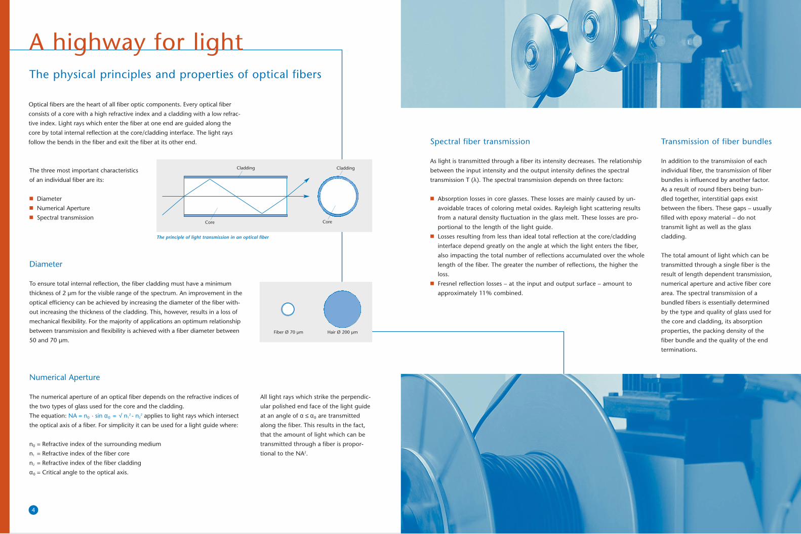
Diameter
To ensure total internal reflection, the fiber cladding must have a minimum
thickness of 2 µm for the visible range of the spectrum. An improvement in the
optical efficiency can be achieved by increasing the diameter of the fiber with-
out increasing the thickness of the cladding. This, however, results in a loss of
mechanical flexibility. For the majority of applications an optimum relationship
between transmission and flexibility is achieved with a fiber diameter between
50 and 70 µm.
4
Optical fibers are the heart of all fiber optic components. Every optical fiber
consists of a core with a high refractive index and a cladding with a low refrac-
tive index. Light rays which enter the fiber at one end are guided along the
core by total internal reflection at the core/cladding interface. The light rays
follow the bends in the fiber and exit the fiber at its other end.
The physical principles and properties of optical fibers
The principle of light transmission in an optical fiber
Core Core
Cladding Cladding
All light rays which strike the perpendic-
ular polished end face of the light guide
at an angle of α ≤ α0 are transmitted
along the fiber. This results in the fact,
that the amount of light which can be
transmitted through a fiber is propor-
tional to the NA2.
Fiber Ø 70 µm Hair Ø 200 µm
Spectral fiber transmission
As light is transmitted through a fiber its intensity decreases. The relationship
between the input intensity and the output intensity defines the spectral
transmission T (λ). The spectral transmission depends on three factors:
■ Absorption losses in core glasses. These losses are mainly caused by un-
avoidable traces of coloring metal oxides. Rayleigh light scattering results
from a natural density fluctuation in the glass melt. These losses are pro-
portional to the length of the light guide. ■ Losses resulting from less than ideal total reflection at the core/cladding
interface depend greatly on the angle at which the light enters the fiber,
also impacting the total number of reflections accumulated over the whole
length of the fiber. The greater the number of reflections, the higher the
loss.■ Fresnel reflection losses – at the input and output surface – amount to
approximately 11% combined.
Transmission of fiber bundles
In addition to the transmission of each
individual fiber, the transmission of fiber
bundles is influenced by another factor.
As a result of round fibers being bun-
dled together, interstitial gaps exist
between the fibers. These gaps – usually
filled with epoxy material – do not
transmit light as well as the glass
cladding.
The total amount of light which can be
transmitted through a single fiber is the
result of length dependent transmission,
numerical aperture and active fiber core
area. The spectral transmission of a
bundled fibers is essentially determined
by the type and quality of glass used for
the core and cladding, its absorption
properties, the packing density of the
fiber bundle and the quality of the end
terminations.
The three most important characteristics
of an individual fiber are its:
■ Diameter ■ Numerical Aperture ■ Spectral transmission
Numerical Aperture
The numerical aperture of an optical fiber depends on the refractive indices of
the two types of glass used for the core and the cladding.
The equation: NA = n0 · sin α0 = √ n12 - n2
2 applies to light rays which intersect
the optical axis of a fiber. For simplicity it can be used for a light guide where:
n0 = Refractive index of the surrounding medium
n1 = Refractive index of the fiber core
n2 = Refractive index of the fiber cladding
α0 = Critical angle to the optical axis.
A highway for light
SCHOTT_04141_Industrietech7.qxd 24.09.2004 12:46 Uhr Seite 4

7
From single fibers to light guides
Bundles of optical fibers are combined with appropriate end terminations and
protective sheathing to form light guides and image guides. Combining well-
proven materials with in-house developed technologies SCHOTT
incorporates such fiber bundles into a multitude of engineered components
by modifying their properties to suit the particular application.
Fiber types
The selected fiber type is dependent on
the demands of the application. SCHOTT
flexible fibers as well as rigid fiber optic
rods cover a variety of diameters and
optical characteristics like Numerical
Aperture and Transmission. Fiber types
for the visible and UV spectral range,
plus several types to accommodate near
IR enable manufacturing of fiber optic
components best suited for a variety of
different applications. For further details
please refer to the actual datasheets.
Flexible or rigid? The first step in designing a fiber optic light guide is the
decision if it needs to be flexible or rigid. Rigid fiber optic rods also referred to
as light conducting rods are solid fiber optic elements which can be used to
transmit light, image or signals over short distances whenever flexibility is not
required. Their advantages over flexible light guides are:
■ No packing losses in interstitial gaps and therefore higher transmission■ Excellent temperature resistance because epoxied end ferrules and
protective sheathings are not required■ Vacuum or pressure seals are possible
In addition, SCHOTT can also manufacture fiber optic cones respective
conical light guides for reducing or increasing the effective optical cross-
section and aperture angle (“Light magnification”). Please contact your local
sales person for further details.
Manufacturing/Design of light guides
Mechanical Protection
Sheathing
Clearly SCHOTT believes that sheathing is more than simply packaging for
fiber bundles; sheathing is an integral structural component used to meet
specific applications.
If, and for how long, a light guide operates reliably depends to a large extent
on the protective sheathing used. SCHOTT offers many different types of
sheathing, so that fiber bundles can be protected in various mechanical,
physical and chemical environments.
A standard range of protective sheathing to suit particular applications is
available (i.e. metal, polymer, compound). Details see separate datasheet.
Ferrules
End ferrules for bonded/epoxied light guides are made out of aluminum,
brass, stainless steel, nickel silver or other materials. For end ferrules in hot
fused components stainless steel is used.
Housings
If requested we can manufacture housings to your specifications. Typical
housing materials are: nickel, silver aluminum, stainless steel and various
plastics.
Spectral Transmission – Different fiber types (fiber Ø 70 µm, length 1000 mm) – Typical values
200 400 600 800 1000 1200 1400 1600 1800 2000 2200 2400
70
60
50
40
30
20
10
0
Tran
smis
sion
(%
)
Wavelength (nm)■ UV fiber ■ IR fiber ■ VIS fiber
Materials
SCHOTT’s competencies …
SCHOTT_04141_Industrietech7.qxd 24.09.2004 12:47 Uhr Seite 6

98
Fiber Drawing
Drawing of glass fibers is a sophisticated
process, which requires a tremendous
amount of experience, thorough engi-
neering, excellent raw materials and
dedicated staff, who just wants to make
the difference.
Technologies
Cable Extrusion
SCHOTT has several extruder lines for continuous manufacturing of optical
cables. Several primary bundles generated on the multi fiber drawing tower,
are fed into the extruder, where the fiber bundle is covered with a liquid
thermoplastic polymer. The extruded cable runs through a cooling bath for
polymerization.
Fiber
Furnacee
Fiber Spool
Lubricant
DiameterControl
Tubing nM Core Glass Rod nK
■ Wide range of cable diameters from a
single 250 µm fiber to 8 mm bundles■ Selection of different polymer materi-
als adapted to the specific application ■ Economic sheathing for single and
multi-branch light guides
The fibers in flexible light guides can be
arranged in different shapes, depending
on the requirements of the application.
This is in particular important for sens-
ing applications, where the size or
assembly of certain detectors must be
met, often by combining multi-branch
assemblies evenly.
Extremely important for several sensing
and most of the illumination applica-
tions is the randomization of fibers.
Fibers from one end of the light guide
will be thoroughly mixed according to
specified procedures to ensure a very
homogeneous illumination pattern.
Thus, hot-spots of lamps on the illumi-
nation end can be evened out over the
entire area at the exit.
Fiber Arrangement
Special randomization processes have been developed for large lightline with
several illumination bundles to ensure that fibers from each bundle are evenly
distributed over the entire length of the bundle.
segmented linear
semi-circular
concentricarbitrary
randomized
Multifiber Drawing
Primary Bundles Extrusion Unit
Cable
A glass system made up out of core bar and tubing material, both thoroughly
cleaned and combined are positioned into a ring furnace. The furnace heats
up the system until the glass softens and finally the viscous glass system can
be formed to a thin fiber by mechanically pulling. The fiber then is redirected
and spooled onto a fiber wheel. The faster the wheel rotates, the thinner the
fiber will be. Thus diameters between 30 and 120 µm can be manufactured.
To protect the fibers against breakage the fiber surface will be covered with a
lubricant right after the drawing process. Different lubricants are available for
specific applications. By combining different core and tube glass materials
optical characteristics like transmission and numerical aperture of the fiber
can be determined. A large selection of fiber types is available. See datasheets
Glass fiber bundles can be extruded with polymer coatings comparable to
copper cables for electricity. This enables production of standard cable diame-
ters on spools for subsequent manufacturing steps – a very efficient method
for high quantity applications.
SCHOTT_04141_Industrietech7.qxd 24.09.2004 12:47 Uhr Seite 8

10
In order to ensure safe operation even
at high temperatures, SCHOTT has
developed a unique end termination
process in which no adhesive is used.
Instead, the fiber ends are fused
together in a process combining heat
with pressure. Fibers made of multi-
component glass are embedded at the
same time in a stainless steel ferrule.
Light guides with hot-fused ends are
particularly suitable for the following
applications:■ Pyrometers (radiation and turbine)■ Spark recognition■ High output illumination systems
End Termination: Grinding & Polishing
In order to efficiently launch or extract light from an optical fiber bundle, the
ends of each fiber must be cut, ground and polished at right angles to their
optical axis – usually perpendicular. Both, the quality and the method of
termination will greatly influence the light guide properties.
Two apparently identical light guides may exhibit different transmission and
angular output characteristics due to light guide assembly and in particular
the way in which the end surfaces have been ground and polished.
In the final stage of production all fibers are optically ground and polished
using special termination techniques to provide our customers with the
highest quality.
End Termination: Epoxying/Hot-Fusing
Spectral Transmission – fiber light guide (fiber Ø 70 mm, length 1000 mm, end tips glued, end tips hot-fused) – Typical values
200 400 600 800 1000 1200 1400 1600 1800 2000 2200 2400
70
60
50
40
30
20
10
0
Tran
smis
sion
(%
)
Wavelength (nm)
■ hot-fused ■ epoxied
epoxied
hot-fused
Benefits of hot-fused ends:
■ High temperature resistance (up to 350 °C for long-term operation).■ High durability in combination with high power light sources.■ No light loss through interstitial gaps between the fibers, which make
no contribution to light transmission. ■ The fusing process is reshaping the fibers predominantly into
hexagonal shape. Thus more fibers can be accommodated in the
same optically effective cross-section resulting in a transmission
increase of 15 % compared with epoxied ends.
To ensure that fiber ends in light guides can be ground and polished perpen-
dicular to their optical axis thus enabling maximum transmission, the ends
need to be terminated. Standard method is epoxying fibers and end ferrule
together. Epoxied light guide ends are temperature stable up to 120 °C. High
temperature epoxies up to 200 °C are available upon request.
Where long-term operation in excess of 200 °C is involved, and particularly
where additional mechanical loads such as pressure, tension, vibration or
acceleration occur at the light guide end, there is a danger of the adhesive
disintegrating and the light guide consequently being damaged.
epoxied
hot-fused
… are at the core of our success
SCHOTT_04141_Industrietech7.qxd 24.09.2004 12:47 Uhr Seite 10

12
Pulling Technology
For longer lengths of lightlines SCHOTT has developed a unique pulling tech-
nology, which in combination with the patented spatially randomizing process
ensures even and homogeneous illumination in length up to 3000 mm.
Fiber bundles are positioned in a fixture and evenly spread out to form a
multi-fiber layer, which is subsequently compacted into a uniform line. The
opposite ends of the fibers are divided into a defined number of flexible arms,
utilizing spatial randomization. This ensures distribution of fibers from each
flexible bundle over the entire width of the line.
The fiber assembly is encased in nosepiece extrusions, which allow flexible
design of light lines in various widths.
The pulling technology is an effective method to manufacture homogeneous
lightlines in various slit dimensions and fiber lengths.
Lightline Technology
To evenly illuminate a strip of light is
one of the most challenging applications
in fiber optic lighting. In particular in
surface inspection applications very even
illuminations over lines up to 3 meter
long are required, which demand the
combination of sophisticated fiber optic
manufacturing methods. SCHOTT devel-
oped two different manufacturing
methods, each one with distinctive
advantages.
Winding Technology
Fibers from a single fiber drawing tower are wound onto a drum, layer by
layer (“online”-winding), creating a “multi layer basic ribbon”. Once the
desired quantity of layers is positioned on the drum, the fibers will be fixed
by clamping a metal bar to them and subsequently epoxying fibers and bar
together.
Several basic ribbons can be combined to a modular system in a common
housing. Specific segmentation of the line or randomization is possible.
Advantage of the winding technology is a very high packing fraction and the
best possible parallelity of fibers, which makes it the technology of choice for
highest demanding lighting and homogeneity requirements in lengths up to
500 mm.
Fibers
Metal bar
Expert solutions …
SCHOTT_04141_Industrietech7.qxd 24.09.2004 12:48 Uhr Seite 12

15
Alternatively to fiber optics with separate light sources inorganic Light Emitting
Diodes are of increasing importance for industrial lighting applications.
The LED semiconductor chip emits radiation proportional to the current
through the LED. The wavelength of the emitted radiation is always discrete.
Today wavelenghts from UV via the visible spectrum to the deep IR are avail-
able on the market. Of increasing importance for lighting applications are
white LEDs. White light though LEDs commonly is generated using a blue
chip with a fluorescent layer. The combination of the blue wavelength and
the yellow fluorescent radiation overlays to white light with color tempera-
tures of approximately 6000 K.
Benefits of LEDs:■ Significant longer lifetime than conventional illuminants■ Excellent electronic controllability, useable for segment control as well as
complete PC control■ Excellent strobeability and remote control options■ Low power consumption■ Noiseless, free of vibration■ Small geometrical dimensions ■ Large range of discrete wavelength available
Single LEDs will be assembled into lightheads in shapes of brightfield and
darkfield ringlights, backlights, lightlines and spotlights. Adding special hard-
ware like dome or coaxial attachments, polarizers, diffusers illuminators
specialty illumination effects can be achieved. Custom designs are available.
To maintain the long lifetime of individual LEDs also in a lighthead assembly
SCHOTT has developed intelligent LED lighting solutions:
for Machine Vision …
■ Temperature Management though heat absorbing hardware and inte-
grated temperature sensor to maintain the maximum allowed LED temper-
atures during operation ■ Matrix circuit design vs. parallel chains reduces the influence of LED fail-
ures to the individual LEDs■ Lightfeedback sensor to compensate for degradation of light output over
time due to altering and change in environmental conditions■ Online control via RS-232-Interface
… SCHOTT iQLED lightheads and controller
Physical principles of LEDs
Transparent epoxy housingwith lens cap
Bond wire
Anode
LED-Chip
Cathode with reflector
Principle design of a LED:
CombinedSpectrum
(white LED)
Phosphoremission
Spectrum blue LED
Design of LED Lighting Components
and Stereo-Microscopy …
■ New contrasting options though segment control of ringlights and
transmitted light stage ■ Rotation of illumination segments■ Freely settable memory positions for easy to use storage of parameters
for fast change in between illumination modes ■ Simple options for mixed light conditions
… SCHOTT VisiLED lightheads and controller
… or the compact SCHOTT EasyLED Ringlight
LCR 100 Ringlight for easy to use bright white light for Stereo-Microscopy.
For further information please ask for SCHOTT’s “Industrial LED Components”
brochure or the individual datasheets.
… guarantee high quality …
SCHOTT_04141_Industrietech7.qxd 24.09.2004 12:48 Uhr Seite 14
17
Leached Technology
SCHOTT’s flexible leached image guides are used in a variety of industrial
endoscopes requiring high resolution image transfer.
Our wide range of sizes enables our image guides to be designed into larger
diameter viewing scopes as well as into smaller instruments with multiple
working channels.
SCHOTT’s high resolution image guides satisfy the stringent standards of
leading OEMs. Our imaging solutions offer a value-based balance of per-
formance, quality and cost.
Physical principles and manufacturing/Design of image guides
Faceplates and Tapers
SCHOTT’s fiber optic faceplates and tapers are used for high resolution image
transfer in CCD coupling, image intensification, x-ray imaging and to meet
other industrial market needs.
Tapers provide virtually distortion-free image transfer with magnification or
minification of the image. Fiber sizes of tapers range from 4 to 25 µm at the
large end to 2 to 6 µm at the small end. Tapers can be machined into shapes
from round to round, rectangular to rectangular, and round to rectangular in
sizes up to 150 mm with magnification ratios up to 4:1.
Fiber sizes of faceplates range from 4 to 25 µm and larger. Shapes range from
round to rectangular. Faceplates are available in sizes up to 150 mm square.
■ The standard numerical aperture of
faceplates and tapers (small end) is
1.0. Numerical apertures of 0.35 and
0.58 are available.■ SCHOTT’s faceplates and tapers are
designed to meet customer specific
requirements.■ SCHOTT’s glass types are designed
for use in the visible and near IR
spectrum. Radiation attenuating and
radiation hardened materials are
available.
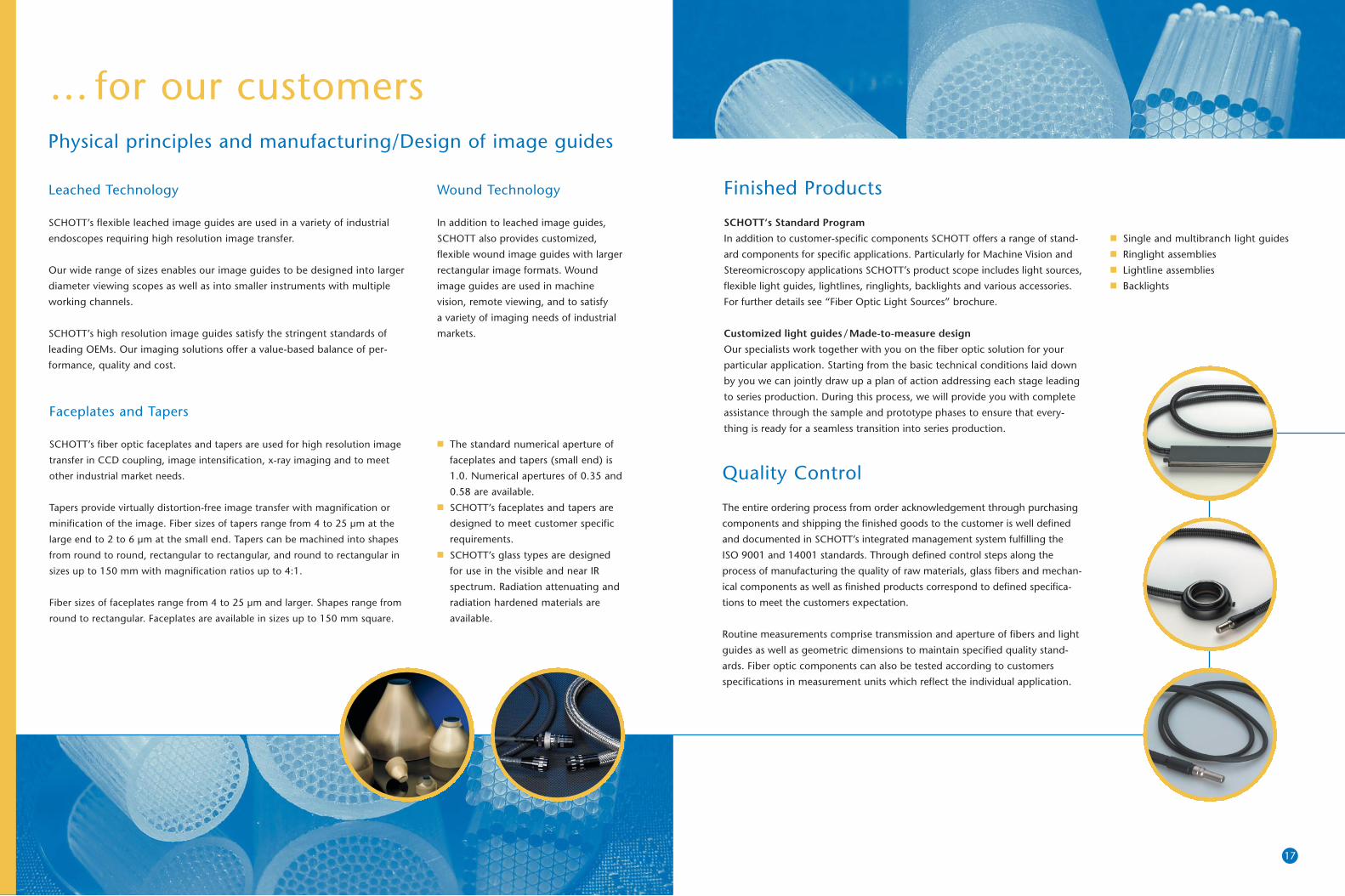
Finished Products
SCHOTT‘s Standard Program
In addition to customer-specific components SCHOTT offers a range of stand-
ard components for specific applications. Particularly for Machine Vision and
Stereomicroscopy applications SCHOTT’s product scope includes light sources,
flexible light guides, lightlines, ringlights, backlights and various accessories.
For further details see “Fiber Optic Light Sources” brochure.
Customized light guides/Made-to-measure design
Our specialists work together with you on the fiber optic solution for your
particular application. Starting from the basic technical conditions laid down
by you we can jointly draw up a plan of action addressing each stage leading
to series production. During this process, we will provide you with complete
assistance through the sample and prototype phases to ensure that every-
thing is ready for a seamless transition into series production.
Quality Control
The entire ordering process from order acknowledgement through purchasing
components and shipping the finished goods to the customer is well defined
and documented in SCHOTT’s integrated management system fulfilling the
ISO 9001 and 14001 standards. Through defined control steps along the
process of manufacturing the quality of raw materials, glass fibers and mechan-
ical components as well as finished products correspond to defined specifica-
tions to meet the customers expectation.
Routine measurements comprise transmission and aperture of fibers and light
guides as well as geometric dimensions to maintain specified quality stand-
ards. Fiber optic components can also be tested according to customers
specifications in measurement units which reflect the individual application.
■ Single and multibranch light guides■ Ringlight assemblies■ Lightline assemblies ■ Backlights
Wound Technology
In addition to leached image guides,
SCHOTT also provides customized,
flexible wound image guides with larger
rectangular image formats. Wound
image guides are used in machine
vision, remote viewing, and to satisfy
a variety of imaging needs of industrial
markets.
… for our customers
SCHOTT_04141_Industrietech7.qxd 24.09.2004 12:48 Uhr Seite 16

Machine Vision and Stereo-Microscopy
Illumination is an important in Machine Vision or Stereo-Microscopy. With
optimized illumination the desired features of the object will be made visible
for the camera respective microscope operator by well-aimed amplification of
the contrast.
Versatility in designs of lightheads enables the application of different lighting
techniques like brightfield, darkfield, transmissive light, diffuse lighting,
polarized light or other specialty illuminations. Wherever a large amount of
light must be distributed homogeneously onto small areas SCHOTT will find
a solution.
Fiber optic illumination is of great importance for Machine Vision and Stereo-
Microscopy applications due to high light intensity of the halogen or metal
halide light sources and the large variability of fiber optic components. Fiber
optic components from SCHOTT distinguish themselves by the following
characteristics:
■ Very high transmission ■ Excellent color temperature ■ Good fiber randomization for very even illumination■ High flexibility ■ Mechanical stability ■ Chemical resistance ■ Temperature resistance up to 350 °C
19
Transmitting light(for industrial lighting applications)
■ Illumination of a specimen in the target area. Special lighting techniques
are used to enhance the contrast to make special features visible.■ Two different options are possible:
1. Illumination from a separate light source (Halogen, Metal Halide or
Xenon) via fiber optic light guide
2. Illumination by means of an LED assembly■ Main applications are Stereo-Microscopy and Machine Vision. ■ Larger range of standard products is described in the brochure
„Fiber Optic Light Sources”
Transmitting signals (for sensors and control applications)
■ Sending or receiving of light or optical signals through optical fibers.■ Light guides used for sensor applications are mostly costumized design
and OEM solutions.■ Application examples are described in the applications section of this
brochure.
Transmitting images (for image transfer applications)
■ Using image bundles with fibers, which consists of millions of individual
fibers that are bonded together in a highly ordered array.■ Image guides are mostly custom or OEM solutions.
LED lighting components increasingly
gain importance for illumination
applications due to their long lifetime
and excellent electronic controllability.
SCHOTT’s LED Illumination systems
offer the customer:
■ Temperature control to keep LED
temperatures within allowed temper-
ature ranges and thus maintain long
lifetimes.■ Stable light output via light feedback
sensor resulting in constant light
over the operating period.■ Segment control for new contrasting
options.
SCHOTT’s products @ work
SCHOTT_04141_Industrietech7.qxd 24.09.2004 12:48 Uhr Seite 18

Thyr
isto
rs a
thi
gh p
oten
tial
Light guides
Receiver with electronics(for conventional firing)
Light sender (ground potential)
21
Pyrometry
Pyrometers are used for the contact-free measurement of surfaces and liquids.
They are used to measure the temperature of turbine blades, for example in
aircraft engines, to avoid damage to the material through over-heating. In this
sensor application, light guides transfer the temperature radiation from the
turbine blades to the pyrometer.
The hot-fused light guide ends in the turbine are temperature-resistant to
350 °C, thus ensuring reliable transfer of the light in spite of extreme temper-
ature, high pressure, vibration, acceleration and chemical influences.
Thyristor control for HVDC
Electrical power requirements are increasing all over the world. An optimal
balance of electrical generation and consumption often means pooling of
resources between networks. With an interconnection made by high voltage
direct current (HVDC) stations, the power exchange between the networks
can be precisely controlled.
The MK light conducting cable developed by Schott as a high voltage resist-
ant cable is particularly well suited for the transmission of data and control
signals required for such applications.
In conventional thyristor firing applications a conversion of the optical signal
into an electrical pulse is required to operate the thyristors. Light-triggering
thyristors are triggered directly by means of a powerful light pulse. The trigger
command from a high power diode at ground potential is transmitted via a
high-voltage resistant light guide to a thyristor at high potential. Light guides
can also be used to monitor the triggering process.
Electricaloutput
Photo receiverwith amplifier
Light guidewith fused ends
Pyrometerhead
Cold air stream
Turbine walling
Hot air stream
Light tube
Guide blades,static
Turbine blades
Spark recognition
In filtering equipment, silos and dryers, dust fires and explosions can often
occur, endangering human life and causing immense material damage.
SCHOTT light guides play an integral part in spark recognition systems. In
case of a spark occurring the light guide transmits the light to a detection
unit, which in turn activates extinguishing equipment meaning the spark can
be automatically put out before it ignites. Due to our hot-fusing process the
spark recognition systems can operate in high-temperature environments.
Spectroscopy
Spectroscopy is the study of molecular
structure and dynamics through the
absorption, emission and scattering of
light. A spectrometer is an instrument
used to break light transmitted through
a sample or emitted light into its various
wavelengths and subsequently analyze.
The light guides facilitate the spatial
separation of signal source, sample and
signal analyzer. By using multi-branch
light guides several individual samples
can be analyzed using only one sender
and receiver.
Unique solutions …
SCHOTT_04141_Industrietech7.qxd 24.09.2004 12:49 Uhr Seite 20

Out of the vast field of applications for rigid or flexible image guides two
are explained in more detail, X-ray imaging and semiconductor inspection.
X-ray imaging
In conventional radiography images are created using a phosphor/film combi-
nation. The resulting images are analog, the signals being highly susceptible
to noise and degradation much as an LP record can skip when contaminated
with dust or dirt.
In digital X-ray imaging, where faceplates and tapers are a key component,
the X-rays are converted into digital images which are not susceptible to
noise. Digital X-ray imaging eliminates the film processing delays, reducing
exposure to radiation by as much as 80 %.
The faceplates and tapers■ provide a surface for a coating such as a phosphor screen,■ protect the CCD surface from physical damage,■ provide an X-ray absorption layer to protect the CCD from x-ray damage
and ■ allow a direct 1:1 coupling with other optical devices
23
In semiconductor manufacturing, microlithography is used to transfer the
pattern of circuitry from a photomask – a quartz plate containing the master
copy of a microscopic IC – to a wafer, a thin slice of silicon or other semicon-
ductor material on which the Ics are made. To be able to manufacture such
Ics microlithography strongly depends on the ability to precisely position the
wafer.
Light guides are used to position the wafers. These light guides are very
complex, in particular as the individual fibers have to be positioned with a
precision of 10 µm.
Several light guides are used to illuminate specific spots, other light guides to
transport the diffracted light to an electronic unit where the signals are anal-
ysed to position the wafer correctly.
Positioning
A good example for positioning is the printing industry. Paper is printed
in various colors and steps. It is thus essential for the paper to be well posi-
tioned during the entire process. This is guaranteed by small “structures and
patterns” on the side of the paper. These are repeatedly illuminated and the
reflected light is then analyzed. Any “mismatch” is corrected immediately.
The measuring system is exposed to high mechanical pressures. In addition,
there is risk of explosion due to evaporating solvent.
The advantages of fiber optics are most welcome: no live parts in the danger
zone and a greater separation distance to the printed sheets meaning better
recognition of marks.
One end of a dual light guide is used to illuminatea specific spot and the other end to transport thereflected light into an electronic unit.
Semiconductor inspection
IC manufacturers continually have to reduce the size of ICs while at the same
time make them perform faster. The required semiconductor manufacturing
machines are thus becoming more and more complex and compact.
While most IC production functions are performed and controlled automat-
ically with the help of complex light guides certain initial production steps
require a visual inspection. As the IC production area is not directly accessible
and is also operated under special environmental conditions, a flexible image
guide is used to transport the required image to the operator allowing him
to visually controll the initial operation.
… for a variety of applications
SCHOTT_04141_Industrietech7.qxd 24.09.2004 12:49 Uhr Seite 22

Fiber OpticsSCHOTT AGOtto-Schott-Str. 255127 MainzGermanyPhone: +49 (0)6131/66-0 or -7752Fax: +49 (0)6131/66-7850E-mail: [email protected]/fiberoptics
Fiber OpticsSCHOTT North America Inc.62 Columbus StreetAuburn, NY 13021-3137USAPhone: +1 (0)315/2552791Fax: +1 (0)315/2552695E-mail: [email protected]/fiberoptics
Fiber OpticsSCHOTT North America Inc.122 Charlton StreetSouthbridge, MA 01550USAPhone: +1 (0)508/7653250Fax: +1 (0)508/7641680E-mail: [email protected]/fiberoptics
Fiber OpticsSCHOTT Nippon K.K.7, Honshio-cho, Shinjuku-kuTokyo 160-0003JapanPhone: +81 (0)3/5366-2548Fax: +81 (0)3/5366-2960E-mail: [email protected]/japan
1014
5 e
1004
5.0
ba/
wo
Prin
ted
in G
erm
any
SCHOTT_04141_Industrietech7.qxd 24.09.2004 12:49 Uhr Seite 24