Embed Size (px)
Citation preview
CSM_NY5__-1_DS_E_3_6
1
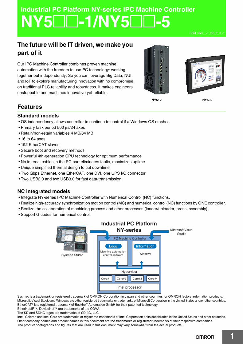
Industrial PC Platform NY-series IPC Machine Controller
NY5@@-1/NY5@@-5The future will be IT driven, we make you part of it
Our IPC Machine Controller combines proven machine automation with the freedom to use PC technology: working together but independently. So you can leverage Big Data, NUI and IoT to explore manufacturing innovation with no compromise on traditional PLC reliability and robustness. It makes engineers unstoppable and machines innovative yet reliable.
FeaturesStandard models• OS independency allows controller to continue to control if a Windows OS crashes• Primary task period 500 μs/24 axes• Retain/non-retain variables 4 MB/64 MB• 16 to 64 axes• 192 EtherCAT slaves• Secure boot and recovery methods• Powerful 4th-generation CPU technology for optimum performance• No internal cables in the PC part eliminates faults, maximizes uptime• Unique simplified thermal design to cut downtime• Two Gbps Ethernet, one EtherCAT, one DVI, one UPS I/O connector• Two USB2.0 and two USB3.0 for fast data-transmission
NC integrated models• Integrate NY-series IPC Machine Controller with Numerical Control (NC) functions.• Realize high-accuracy synchronization motion control (MC) and numerical control (NC) functions by ONE controller.• Realize the collaboration of machining process and other processes (loader/unloader, press, assembly).• Support G codes for numerical control.
Sysmac is a trademark or registered trademark of OMRON Corporation in Japan and other countries for OMRON factory automation products.Microsoft, Visual Studio and Windows are either registered trademarks or trademarks of Microsoft Corporation in the United States and/or other countries.EtherCAT® is a registered trademark of Beckhoff Automation GmbH for their patented technology.EtherNet/IPTM, DeviceNetTM are trademarks of the ODVA.The SD and SDHC logos are trademarks of SD-3C, LLC.Intel, Celeron and Intel Core are trademarks or registered trademarks of Intel Corporation or its subsidiaries in the United States and other countries.Other company names and product names in this document are the trademarks or registered trademarks of their respective companies.The product photographs and figures that are used in this document may vary somewhat from the actual products.
NY512 NY532
Sysmac Studio
Industrial PC Platform NY-series
IPC Machine Controller
Microsoft Visual Studio
Intel processor
Hypervisor
Core#2 Core#3Core#1 Core#4
Machine automation control software Windows
Logic Information
NY5@@-1/NY5@@-5
2
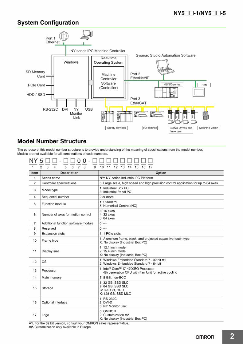
System Configuration
Model Number StructureThe purpose of this model number structure is to provide understanding of the meaning of specifications from the model number.Models are not available for all combinations of code numbers.
*1. For the 32 bit version, consult your OMRON sales representative.*2. Customization only available in Europe.
Item Description Option1 Series name NY: NY-series Industrial PC Platform
2 Controller specifications 5: Large scale, high speed and high precision control application for up to 64 axes.
3 Model type 1: Industrial Box PC3: Industrial Panel PC
4 Sequential number 2 or more
5 Function module 1: Standard5: Numerical Control (NC)
6 Number of axes for motion control3: 16 axes4: 32 axes5: 64 axes
7 Additional function software module 0: ---
8 Reserved 0: ---
9 Expansion slots 1: 1 PCle slots
10 Frame type 1: Aluminum frame, black, and projected capacitive touch typeX: No display (Industrial Box PC)
11 Display size1: 12.1 inch model2: 15.4 inch modelX: No display (Industrial Box PC)
12 OS 1: Windows Embedded Standard 7 - 32 bit *12: Windows Embedded Standard 7 - 64 bit
13 Processor 1: Intel® Core™ i7-4700EQ Processor4th generation CPU with Fan Unit for active cooling
14 Main memory 3: 8 GB, non-ECC
15 Storage
8: 32 GB, SSD SLC9: 64 GB, SSD SLCC: 320 GB, HDDK: 128 GB, SSD MLC
16 Optional interface1: RS-232C2: DVI-D6: NY Monitor Link
17 Logo0: OMRON2: Customization *2X: No display (Industrial Box PC)
Real-timeOperating System
NY-series IPC Machine Controller
EtherCAT
Sysmac Studio Automation Software
EtherNet/IP
Ethernet
Windows
SD MemoryCard
PCIe Card
HDD / SSD
RS-232C DVI USB
Port 3
Port 2
Port 1
NY Monitor
Link
MachineControllerSoftware
(Controller)
Machine visionServo Drives and Inverters
I/O controlsSafety devices
NJ/NX-series HMI
NY 5 @ @ - @ @ 0 0 - @ @ @ @ @ @ @ @ @1 2 3 4 5 6 7 8 9 10 11 12 13 14 15 16 17
3
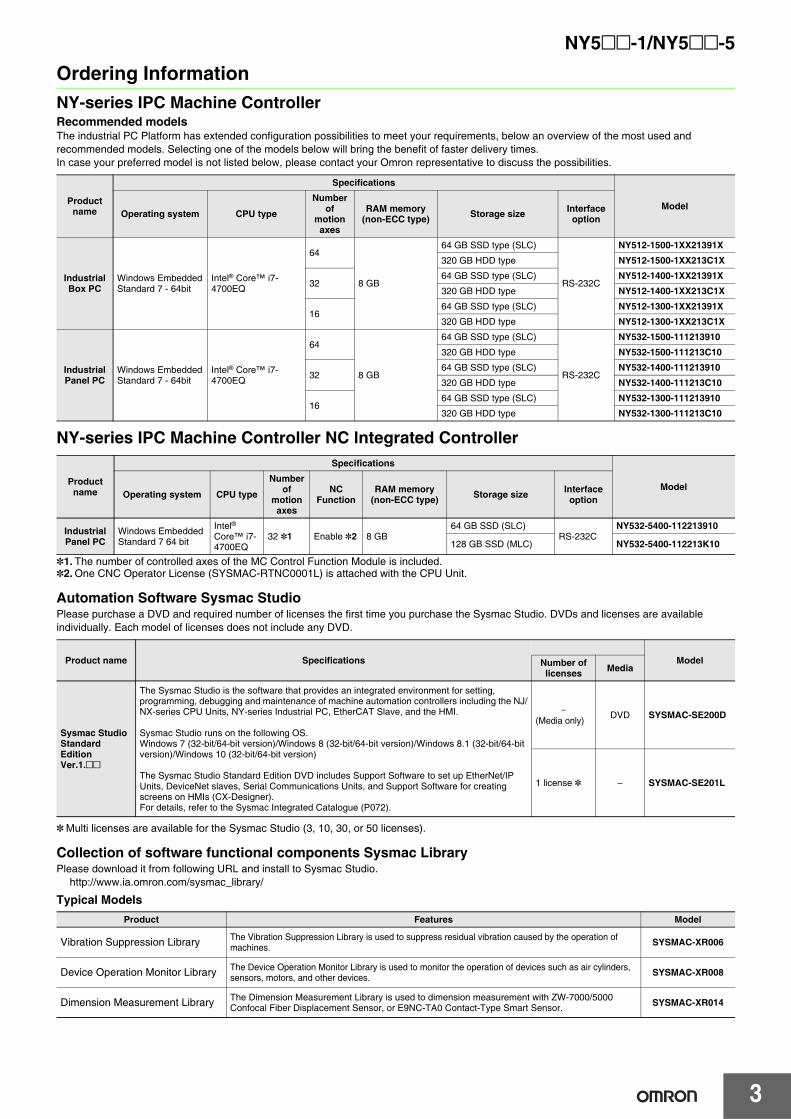
NY5@@-1/NY5@@-5Ordering InformationNY-series IPC Machine ControllerRecommended modelsThe industrial PC Platform has extended configuration possibilities to meet your requirements, below an overview of the most used and recommended models. Selecting one of the models below will bring the benefit of faster delivery times.In case your preferred model is not listed below, please contact your Omron representative to discuss the possibilities.
NY-series IPC Machine Controller NC lntegrated Controller
*1. The number of controlled axes of the MC Control Function Module is included.*2. One CNC Operator License (SYSMAC-RTNC0001L) is attached with the CPU Unit.
Automation Software Sysmac StudioPlease purchase a DVD and required number of licenses the first time you purchase the Sysmac Studio. DVDs and licenses are available individually. Each model of licenses does not include any DVD.
* Multi licenses are available for the Sysmac Studio (3, 10, 30, or 50 licenses).
Collection of software functional components Sysmac LibraryPlease download it from following URL and install to Sysmac Studio.
http://www.ia.omron.com/sysmac_library/
Typical Models
Product name
Specifications
ModelOperating system CPU type
Number of
motion axes
RAM memory(non-ECC type) Storage size Interface
option
Industrial Box PC
Windows EmbeddedStandard 7 - 64bit
Intel® Core™ i7-4700EQ
64
8 GB
64 GB SSD type (SLC)
RS-232C
NY512-1500-1XX21391X
320 GB HDD type NY512-1500-1XX213C1X
3264 GB SSD type (SLC) NY512-1400-1XX21391X
320 GB HDD type NY512-1400-1XX213C1X
1664 GB SSD type (SLC) NY512-1300-1XX21391X320 GB HDD type NY512-1300-1XX213C1X
Industrial Panel PC
Windows EmbeddedStandard 7 - 64bit
Intel® Core™ i7-4700EQ
64
8 GB
64 GB SSD type (SLC)
RS-232C
NY532-1500-111213910
320 GB HDD type NY532-1500-111213C10
3264 GB SSD type (SLC) NY532-1400-111213910
320 GB HDD type NY532-1400-111213C10
1664 GB SSD type (SLC) NY532-1300-111213910320 GB HDD type NY532-1300-111213C10
Product name
Specifications
ModelOperating system CPU type
Number of
motion axes
NC Function
RAM memory(non-ECC type) Storage size Interface
option
Industrial Panel PC
Windows Embedded Standard 7 64 bit
Intel® Core™ i7-4700EQ
32 *1 Enable *2 8 GB64 GB SSD (SLC)
RS-232CNY532-5400-112213910
128 GB SSD (MLC) NY532-5400-112213K10
Product name Specifications ModelNumber of licenses Media
Sysmac Studio Standard Edition Ver.1.@@
The Sysmac Studio is the software that provides an integrated environment for setting, programming, debugging and maintenance of machine automation controllers including the NJ/NX-series CPU Units, NY-series Industrial PC, EtherCAT Slave, and the HMI.
Sysmac Studio runs on the following OS.Windows 7 (32-bit/64-bit version)/Windows 8 (32-bit/64-bit version)/Windows 8.1 (32-bit/64-bit version)/Windows 10 (32-bit/64-bit version)
The Sysmac Studio Standard Edition DVD includes Support Software to set up EtherNet/IP Units, DeviceNet slaves, Serial Communications Units, and Support Software for creating screens on HMIs (CX-Designer).For details, refer to the Sysmac Integrated Catalogue (P072).
−(Media only) DVD SYSMAC-SE200D
1 license * − SYSMAC-SE201L
Product Features Model
Vibration Suppression Library The Vibration Suppression Library is used to suppress residual vibration caused by the operation of machines. SYSMAC-XR006
Device Operation Monitor Library The Device Operation Monitor Library is used to monitor the operation of devices such as air cylinders, sensors, motors, and other devices. SYSMAC-XR008
Dimension Measurement Library The Dimension Measurement Library is used to dimension measurement with ZW-7000/5000 Confocal Fiber Displacement Sensor, or E9NC-TA0 Contact-Type Smart Sensor. SYSMAC-XR014
4
NY5@@-1/NY5@@-5
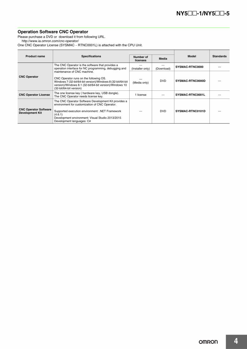
Operation Software CNC OperatorPlease purchase a DVD or download it from following URL.
http://www.ia.omron.com/cnc-operator/One CNC Operator License (SYSMAC − RTNC0001L) is attached with the CPU Unit.
Product name Specifications Model StandardsNumber of licenses Media
CNC Operator
The CNC Operator is the software that provides a operation interface for NC programming, debugging and maintenance of CNC machine.
CNC Operator runs on the following OS.Windows 7 (32-bit/64-bit version)/Windows 8 (32-bit/64-bit version)/Windows 8.1 (32-bit/64-bit version)/Windows 10 (32-bit/64-bit version)
---(Installer only)
---(Download) SYSMAC-RTNC0000 ---
---(Media only) DVD SYSMAC-RTNC0000D ---
CNC Operator License The one license key ( hardware key, USB dongle).The CNC Operator needs license key. 1 license --- SYSMAC-RTNC0001L ---
CNC Operator SoftwareDevelopment Kit
The CNC Operator Software Development Kit provides a environment for customization of CNC Operator.
Supported execution environment: .NET Framework (4.6.1)Development environment: Visual Studio 2013/2015Development languages: C#
--- DVD SYSMAC-RTNC0101D ---
5
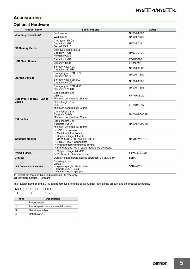
NY5@@-1/NY5@@-5AccessoriesOptional Hardware
*1. Select the required type. Industrial Box PC type only.*2. Revision number 04 or higher.
The revision number of the UPS can be retrieved from the serial number label on the product and the product packaging.
Product name Specifications Model
Mounting Brackets *1Book mount NY000-AB00Wall mount NY000-AB01
SD Memory Cards
Card type: SD CardCapacity: 2 GBFormat: FAT16
HMC-SD291
Card type: SDHC CardCapacity: 4 GBFormat: FAT32
HMC-SD491
USB Flash DrivesCapacity: 2 GB FZ-MEM2GCapacity: 8 GB FZ-MEM8G
Storage Devices
Storage type: HDDCapacity: 320 GB NY000-AH00
Storage type: SSD SLCCapacity: 32 GB NY000-AS00
Storage type: SSD SLCCapacity: 64 GB NY000-AS01
Storage type: SSD MLCCapacity: 128 GB NY000-AS02
USB Type-A to USB Type-B Cables
Cable length: 2 mUSB 2.0Minimum bend radius: 25 mm
FH-VUAB 2M
Cable length: 5 mUSB 2.0Minimum bend radius: 25 mm
FH-VUAB 5M
DVI Cables
Cable length: 2 mSupports DVI-DMinimum bend radius: 36 mm
NY000-AC00 2M
Cable length: 5 mSupports DVI-DMinimum bend radius: 36 mm
NY000-AC00 5M
Industrial Monitor
• LCD touchscreen• Multi-touch functionality• Supply voltage: 24 VDC• Up to 1,280 x 800 pixels at 60 Hz• 2 USB Type-A Connectors• Programmable brightness control• Standard and 100 m cable models are available.
NYM1@W-C10@@
Power Supply • Output voltage: 24 VDC• Push-In Plus terminal blocks S8VK-S@@@24
UPS *2 Output voltage during backup operation: 24 VDC ± 5% S8BA
UPS Communication Cable
Cable length: 2 mSignals for• Signal output (BL, TR, BU, WB)• Remote ON/OFF input• UPS Stop Signal input (BS)
S8BW-C02
A3@ @@@@@@@@@ @@ @1 2 3 4
Item Description1 Product code2 Product period and sequential number3 Revision number4 RoHS status
NY5@@-1/NY5@@-5
6
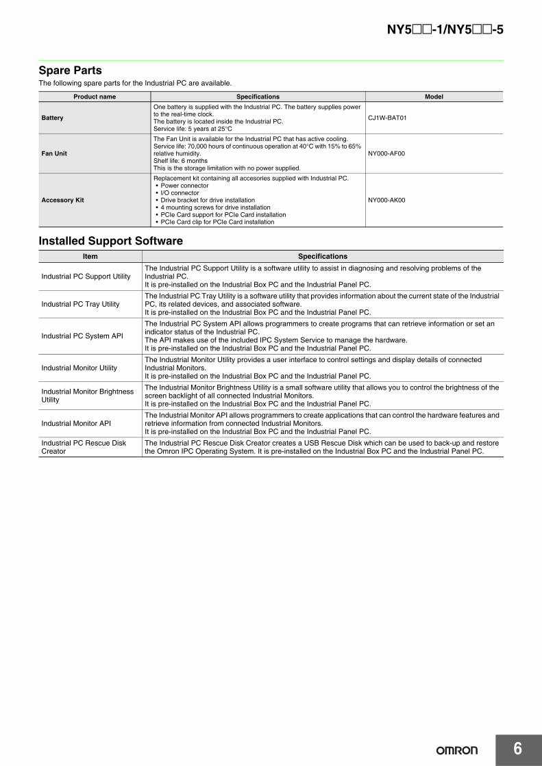
Spare PartsThe following spare parts for the Industrial PC are available.
Installed Support Software
Product name Specifications Model
Battery
One battery is supplied with the Industrial PC. The battery supplies power to the real-time clock.The battery is located inside the Industrial PC.Service life: 5 years at 25°C
CJ1W-BAT01
Fan Unit
The Fan Unit is available for the Industrial PC that has active cooling.Service life: 70,000 hours of continuous operation at 40°C with 15% to 65% relative humidity.Shelf life: 6 monthsThis is the storage limitation with no power supplied.
NY000-AF00
Accessory Kit
Replacement kit containing all accesories supplied with Industrial PC.• Power connector• I/O connector• Drive bracket for drive installation• 4 mounting screws for drive installation• PCIe Card support for PCIe Card installation• PCIe Card clip for PCIe Card installation
NY000-AK00
Item Specifications
Industrial PC Support UtilityThe Industrial PC Support Utility is a software utility to assist in diagnosing and resolving problems of the Industrial PC.It is pre-installed on the Industrial Box PC and the Industrial Panel PC.
Industrial PC Tray UtilityThe Industrial PC Tray Utility is a software utility that provides information about the current state of the Industrial PC, its related devices, and associated software. It is pre-installed on the Industrial Box PC and the Industrial Panel PC.
Industrial PC System API
The Industrial PC System API allows programmers to create programs that can retrieve information or set an indicator status of the Industrial PC.The API makes use of the included IPC System Service to manage the hardware.It is pre-installed on the Industrial Box PC and the Industrial Panel PC.
Industrial Monitor UtilityThe Industrial Monitor Utility provides a user interface to control settings and display details of connected Industrial Monitors.It is pre-installed on the Industrial Box PC and the Industrial Panel PC.
Industrial Monitor Brightness Utility
The Industrial Monitor Brightness Utility is a small software utility that allows you to control the brightness of the screen backlight of all connected Industrial Monitors.It is pre-installed on the Industrial Box PC and the Industrial Panel PC.
Industrial Monitor APIThe Industrial Monitor API allows programmers to create applications that can control the hardware features and retrieve information from connected Industrial Monitors.It is pre-installed on the Industrial Box PC and the Industrial Panel PC.
Industrial PC Rescue Disk Creator
The Industrial PC Rescue Disk Creator creates a USB Rescue Disk which can be used to back-up and restore the Omron IPC Operating System. It is pre-installed on the Industrial Box PC and the Industrial Panel PC.
7
NY5@@-1/NY5@@-5
Recommended EtherCAT and EtherNet/IP Communications CablesUse a straight STP (shielded twisted-pair) cable of category 5 or higher with double shielding (aluminum tape and braiding) for EtherCAT.For EtherNet/IP, required specification for the communications cables varies depending on the baud rate. For 100BASE-TX/10BASE-T, use a straight or cross STP (shielded twisted-pair) cable of category 5 or higher.For 1000BASE-T, use a straight or cross STP cable of category 5e or higher with double shielding (aluminum tape and braiding).
Cabel with Connectors
*1. Cables with standard RJ45 plugs are available in the following lengths: 0.2 m, 0.3 m, 0.5 m, 1 m, 1.5 m, 2 m, 3 m, 5 m, 7.5 m, 10 m, 15 m, 20 m.Cables with rugged RJ45 plugs are available in the following lengths: 0.3 m, 0.5 m, 1 m, 2 m, 3 m, 5 m, 10 m, 15 m.For details, refer to the Industrial Ethernet Connectors Catalog (Cat. No. G019).
*2. The lineup features Low Smoke Zero Halogen cables for in-cabinet use and PUR cables for out-of-cabinet use. Although the LSZH cable is single shielded, its communications and noise characteristics meet the standards.
*3. Cable colors are available in yellow, green, and blue.*4. For details, contact your OMRON representative.
Cables / Connectors
*1. We recommend you to use above Cable, and RJ45 Connector together.*2. We recommend you to use above Cable, and RJ45 Assembly Connector together.Note: Connect both ends of cable shielded wires to the connector hoods.
Item Appearance Recommended manufacturer
Cable length (m) Model
Cable with Connectors on Both Ends (RJ45/RJ45)Standard RJ45 plugs type *1Wire Gauge and Number of Pairs: AWG26, 4-pair CableCable Sheath material: LSZH *2Cable color: Yellow *3
OMRON
0.3 XS6W-6LSZH8SS30CM-Y
0.5 XS6W-6LSZH8SS50CM-Y
1 XS6W-6LSZH8SS100CM-Y2 XS6W-6LSZH8SS200CM-Y
3 XS6W-6LSZH8SS300CM-Y
5 XS6W-6LSZH8SS500CM-Y
Cable with Connectors on Both Ends (RJ45/RJ45)Rugged RJ45 plugs type *1Wire Gauge and Number of Pairs: AWG22, 2-pair CableCable color: Right blue
OMRON
0.3 XS5W-T421-AMD-K
0.5 XS5W-T421-BMD-K
1 XS5W-T421-CMD-K2 XS5W-T421-DMD-K
5 XS5W-T421-GMD-K
10 XS5W-T421-JMD-K
Cable with Connectors on Both Ends (M12 Straight/M12 Straight)Shield Strengthening Connector cable *4M12/Smartclick ConnectorsWire Gauge and Number of Pairs: AWG22, 2-pair CableCable color: Black
OMRON
0.5 XS5W-T421-BM2-SS
1 XS5W-T421-CM2-SS
2 XS5W-T421-DM2-SS3 XS5W-T421-EM2-SS
5 XS5W-T421-GM2-SS
10 XS5W-T421-JM2-SS
Cable with Connectors on Both Ends (M12 Straight/RJ45)Shield Strengthening Connector cable *4M12/Smartclick ConnectorsRugged RJ45 plugs type Wire Gauge and Number of Pairs: AWG22, 2-pair CableCable color: Black
OMRON
0.5 XS5W-T421-BMC-SS1 XS5W-T421-CMC-SS
2 XS5W-T421-DMC-SS
3 XS5W-T421-EMC-SS5 XS5W-T421-GMC-SS
10 XS5W-T421-JMC-SS
Item Recommended manufacturer Model
Products for EtherCAT or EtherNet/IP(1000BASE-T/100BASE-TX)
Wire Gauge and Number of Pairs: AWG24, 4-pair Cable
Cables
Hitachi Metals, Ltd. NETSTAR-C5E SAB 0.5 × 4P *1
Kuramo Electric Co. KETH-SB *1
SWCC Showa Cable Systems Co. FAE-5004 *1
RJ45 Connectors Panduit Corporation MPS588-C *1
Products for EtherCAT or EtherNet/IP(100BASE-TX/10BASE-T)
Wire Gauge and Number of Pairs: AWG22, 2-pair Cable
CablesKuramo Electric Co. KETH-PSB-OMR *2
JMACS Japan Co., Ltd. PNET/B *2
RJ45 Assembly Connector
OMRON XS6G-T421-1 *2
NY5@@-1/NY5@@-5
8
SpecificationsPerformance Specifications Supported by NY5@@-1/NY5@@-5
ItemNY5@@-
15@@ 14@@/5400 13@@
Processing time
Instruction execution times
LD instruction 0.33 ns
Math instructions (for Long Real Data) 1.2 ns or more
Programming
Program capacity *1
Size 40 MB
NumberPOU definition 3,000
POU instance 24,000
Variables capacity
No retain attribute
Size 64 MB
Number 180,000
Retain attributeSize 4 MB
Number 40,000
Data type Number 4,000
Unit configuration
Maximum number of connectable units Maximum number of NX unit on the system 4,096 (on NX series EtherCAT slave terminal)
Motion control
Number of controlled axes
Maximum number of controlled axes
Maximum number of axes which can be defined.The number of controlled axes = The number of motion control axes + The number of single-axis position control axes.
64 axes 32 axes 16 axes
Motion control axesMaximum number of motion control axes which can be defined. All motion control function is available.
64 axes 32 axes 16 axes
Maximum number of used real axesMaximum number of used real axes.The Number of used real axes includes following servo axes and encoder axes.
Used motion control servo axes
Maximum number of servo axes which all motion control function is available.The number of used motion control servo axes = The number of motion control axes whose axis type is set to servo axis and axis use is set to used axis.
64 axes 32 axes 16 axes
Maximum number of axes for linear interpolation axis control 4 axes per axes group
Number of axes for circular interpolation axis control 2 axes per axes group
Maximum number of axes groups 32 axes groups
Motion control period The same control period as that is used for the process data communications cycle for EtherCAT.
CamsNumber of cam data points
Maximum points per cam table 65,535 points
Maximum points for all cam tables 1,048,560 points
Maximum number of cam tables 640 tables
Position units Pulses, millimeters, micrometers, nanometers, degrees and inches
Override factors 0.00% or 0.01% to 500.00%
*1. This is the capacity for the execution objects and variable tables (including variable names).
NY5@@-1/NY5@@-5
9
*2. Data will be refreshed at the set interval, regardless of the number of nodes.*3. "pps" means packets per second, i.e., the number of communications packets that can be sent or received in one second.*4. As the EtherNet/IP port implements the IGMP client, unnecessary multi-cast packets can be filtered by using a switching hub that supports
IGMP Snooping.
Built-in EtherNet/IP Port
Number of port 1
Physical layer 10BASE-T/100BASE-TX/1000BASE-T
Frame length 1,514 max.
Media access method CSMA/CD
Modulation Baseband
Topology Star
Baud rate 1Gbps (1000BASE-T)
Transmission media STP (shielded, twisted-pair) cable of Ethernet category 5, 5e or higher
Maximum transmission distance between Ethernet switch and node 100 m
Maximum number of cascade connections There are no restrictions if Ethernet switch is used.
CIP service: Tag data links (Cyclic communications)
Maximum number of connections 128
Packet interval *2 1 to 10,000 ms in 1.0-ms incrementsCan be set for each connection.
Permissible communications band *3 20,000 pps including heartbeat
Maximum number of tag sets 128
Tag types Network variables
Number of tags per connection (i.e., per tag set) 8 (7 tags if Controller status is included in the tag set.)
Maximum link data size per node (total size for all tags) 184,832 byte
Maximum number of tag 256
Maximum data size per connection 1,444 bytes
Maximum number of registrable tag sets 128 (1 connection = 1 tag set)
Maximum tag set size 1,444 bytes(Two bytes are used if Controller status is included in the tag set.)
Multi-cast packet filter *4 Supported.
Cip Message Service: explicit messages
Class 3 (number of connections) 64 (clients plus server)
UCMM (non-connection type)
Maximum number of clients that can communicate at one time 32
Maximum number of servers that can communicate at one time 32
Maximum number of TCP socket service 30
Built-in EtherCAT port
Number of port 1
Communications standard IEC 61158 Type12
EtherCAT master specifications Class B (Feature Pack Motion Control compliant)
Physical layer 100BASE-TX
Modulation Baseband
Baud rate 100 Mbps (100Base-TX)
Duplex mode Auto
Topology Line, daisy chain, and branching
Transmission media Twisted-pair cable of category 5 or higher (double-shielded straight cable with aluminum tape and braiding)
Maximum transmission distance between nodes 100 m
Maximum number of slaves 192
Range of node address 1-512
Maximum process data sizeInputs: 5,736 bytesOutputs: 5,736 bytes (However, the maximum number of process data frames is 4.)
Maximum process data size per slave Inputs: 1,434 bytesOutputs: 1,434 bytes
Communications cycle 500 μs to 8 ms (in 250-μs increments)
Sync jitter 1 μs max.
Internal clockAt ambient temperature of 55°C: -3.5 to +0.5 min error per monthAt ambient temperature of 25°C: -1.5 to +1.5 min error per monthAt ambient temperature of 0°C: -3 to +1 min error per month
ItemNY5@@-
15@@ 14@@/5400 13@@
10
NY5@@-1/NY5@@-5
Performance Specifications Supported by NY5@@-5
*1. The number of controlled axes of the MC Control Function Module is included.*2. The number of programs and their capacities that can be loaded into the CPU Unit at the same time. The program capacity is the maximum
size available. As fragmentation will occur, the size that is actually available will be smaller than the maximum size.*3. Some parts of the area are reserved by the system.
ItemNY532-
5400
Numerical Control
Task periodPrimary periodic cycle 500/1,000/2,000/4,000 μs
CNC Planner Service period 500 us to 16 ms
Number of CNC motors Maximum number of CNC motors *1 32
CNC coordinate system
Maximum number of CNC coordinate systems 8
Maximum number of CNC motor configurations that are included in a CNC coordinate system(excluding spindle axes)
8
Number of spindle axes that are included in a CNC coordinate system 1
Number of simultaneous interpolation axes 4
NC Program
Program buffer size *2 64 MB
Maximum number of programs
Upper limit of main registrations 512
Upper limit of sub registrations 512
NC program variables
P variable Double-precision floating point 65536 *3
Q variable Double-precision floating point 8192 *3
L variable Double-precision floating point 256
CNC motor compensation table
Maximum number of CNC motor compensation tables 64
Maximum size of all compensation tables 2 MB
NY5@@-1/NY5@@-5
11
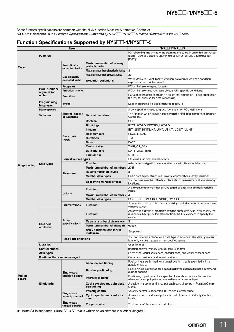
Some function specifications are common with the NJ/NX-series Machine Automation Controller."CPU Unit" described in the Function Specifications Supported by NY5@@-1/NY5@@-5 means "Controller" in the NY Series.
Function Specifications Supported by NY5@@-1/NY5@@-5Item NY5@@-1/NY5@@-5
Tasks
FunctionI/O refreshing and the user program are executed in units that are called tasks. Tasks are used to specify execution conditions and execution priority.
Periodically executed tasks
Maximum number of primary periodic tasks 1
Maximum number of periodic tasks 3
Conditionally executed tasks
Maximum number of event tasks 32
Execution conditions When Activate Event Task instruction is executed or when condition expression for variable is met.
Programming
POU (program organization units)
Programs POUs that are assigned to tasks.Function blocks POUs that are used to create objects with specific conditions.
Functions POUs that are used to create an object that determine unique outputs for the inputs, such as for data processing.
Programming languages Types Ladder diagrams *1 and structured text (ST)
Namespaces A concept that is used to group identifiers for POU definitions.
Variables External access of variables Network variables The function which allows access from the HMI, host computers, or other
Controllers
Data types
Basic data types
Boolean BOOLBit strings BYTE, WORD, DWORD, LWORDIntegers INT, SINT, DINT,LINT, UINT, USINT, UDINT, ULINT
Real numbers REAL, LREALDurations TIMEDates DATE
Times of day TIME_OF_DAYDate and time DATE_AND_TIME
Text strings STRINGDerivative data types Structures, unions, enumerations
Structures
Function A derivative data type that groups together data with different variable types.
Maximum number of members 2048Nesting maximum levels 8Member data types Basic data types, structures, unions, enumerations, array variables
Specifying member offsets You can use member offsets to place structure members at any memory locations.
UnionsFunction A derivative data type that groups together data with different variable
types.Maximum number of members 4Member data types BOOL, BYTE, WORD, DWORD, LWORD
Enumerations Function A derivative data type that uses text strings called enumerators to express variable values.
Data type attributes
Array specifications
FunctionAn array is a group of elements with the same data type. You specify the number (subscript) of the element from the first element to specify the element.
Maximum number of dimensions 3
Maximum number of elements 65535Array specifications for FB instances Supported.
Range specifications You can specify a range for a data type in advance. The data type can take only values that are in the specified range.
Libraries User libraries
Motion control
Control modes position control, velocity control, torque controlAxis types Servo axes, virtual servo axes, encoder axes, and virtual encoder axesPositions that can be managed Command positions and actual positions
Single-axis
Single-axis position control
Absolute positioning Positioning is performed for a target position that is specified with an absolute value.
Relative positioning Positioning is performed for a specified travel distance from the command current position.
Interrupt feeding Positioning is performed for a specified travel distance from the position where an interrupt input was received from an external input.
Cyclic synchronous absolute positioning
A positioning command is output each control period in Position Control Mode.
Single-axis velocity control
Velocity control Velocity control is performed in Position Control Mode.
Cyclic synchronous velocity control
A velocity command is output each control period in Velocity Control Mode.
Single-axis torque control Torque control The torque of the motor is controlled.
*1. Inline ST is supported. (Inline ST is ST that is written as an element in a ladder diagram.)
NY5@@-1/NY5@@-5
12
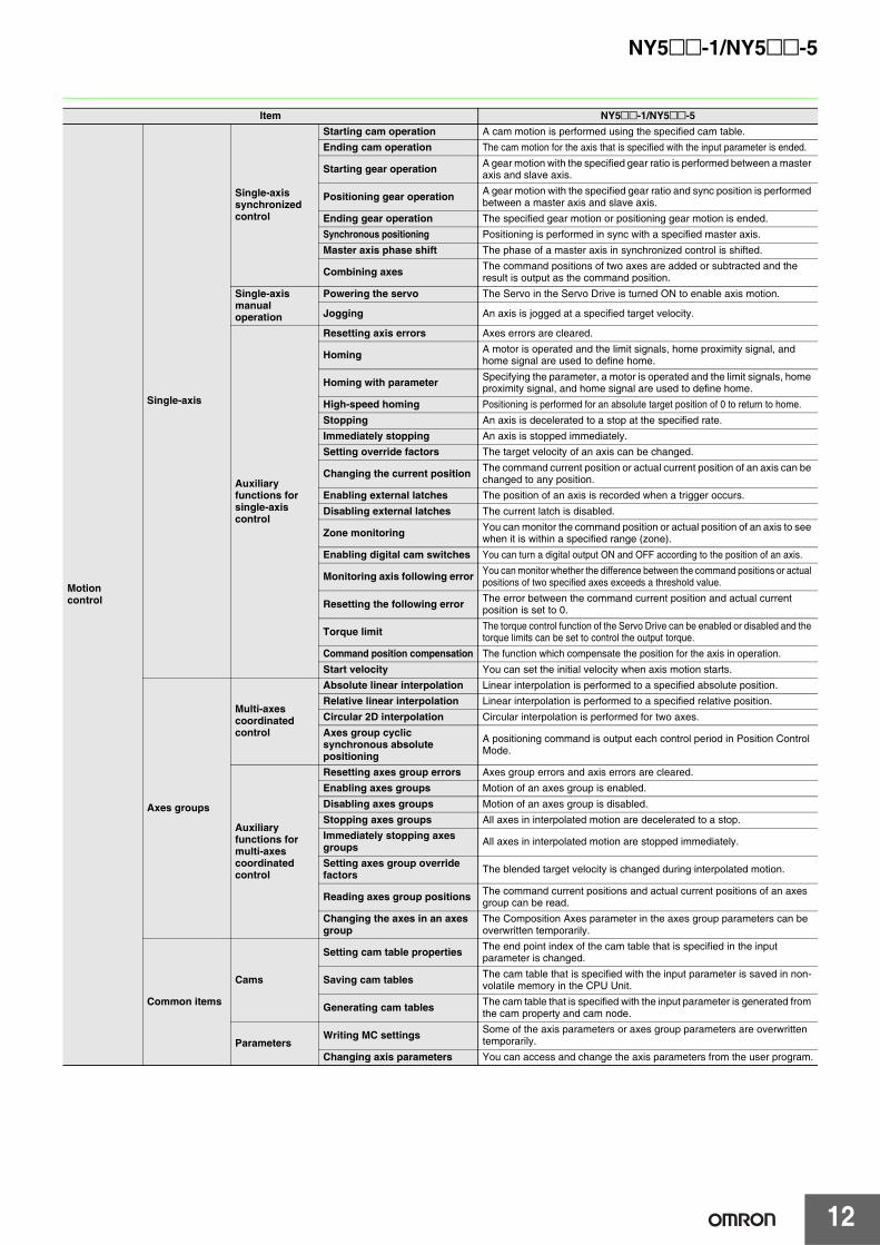
Motion control
Single-axis
Single-axis synchronized control
Starting cam operation A cam motion is performed using the specified cam table.Ending cam operation The cam motion for the axis that is specified with the input parameter is ended.
Starting gear operation A gear motion with the specified gear ratio is performed between a master axis and slave axis.
Positioning gear operation A gear motion with the specified gear ratio and sync position is performed between a master axis and slave axis.
Ending gear operation The specified gear motion or positioning gear motion is ended.Synchronous positioning Positioning is performed in sync with a specified master axis.
Master axis phase shift The phase of a master axis in synchronized control is shifted.
Combining axes The command positions of two axes are added or subtracted and the result is output as the command position.
Single-axis manual operation
Powering the servo The Servo in the Servo Drive is turned ON to enable axis motion.
Jogging An axis is jogged at a specified target velocity.
Auxiliary functions for single-axis control
Resetting axis errors Axes errors are cleared.
Homing A motor is operated and the limit signals, home proximity signal, and home signal are used to define home.
Homing with parameter Specifying the parameter, a motor is operated and the limit signals, home proximity signal, and home signal are used to define home.
High-speed homing Positioning is performed for an absolute target position of 0 to return to home.
Stopping An axis is decelerated to a stop at the specified rate.Immediately stopping An axis is stopped immediately.Setting override factors The target velocity of an axis can be changed.
Changing the current position The command current position or actual current position of an axis can be changed to any position.
Enabling external latches The position of an axis is recorded when a trigger occurs.
Disabling external latches The current latch is disabled.
Zone monitoring You can monitor the command position or actual position of an axis to see when it is within a specified range (zone).
Enabling digital cam switches You can turn a digital output ON and OFF according to the position of an axis.
Monitoring axis following error You can monitor whether the difference between the command positions or actual positions of two specified axes exceeds a threshold value.
Resetting the following error The error between the command current position and actual current position is set to 0.
Torque limit The torque control function of the Servo Drive can be enabled or disabled and the torque limits can be set to control the output torque.
Command position compensation The function which compensate the position for the axis in operation.
Start velocity You can set the initial velocity when axis motion starts.
Axes groups
Multi-axes coordinated control
Absolute linear interpolation Linear interpolation is performed to a specified absolute position.Relative linear interpolation Linear interpolation is performed to a specified relative position.
Circular 2D interpolation Circular interpolation is performed for two axes.Axes group cyclic synchronous absolute positioning
A positioning command is output each control period in Position Control Mode.
Auxiliary functions for multi-axes coordinated control
Resetting axes group errors Axes group errors and axis errors are cleared.Enabling axes groups Motion of an axes group is enabled.
Disabling axes groups Motion of an axes group is disabled.Stopping axes groups All axes in interpolated motion are decelerated to a stop.Immediately stopping axes groups All axes in interpolated motion are stopped immediately.
Setting axes group override factors The blended target velocity is changed during interpolated motion.
Reading axes group positions The command current positions and actual current positions of an axes group can be read.
Changing the axes in an axes group
The Composition Axes parameter in the axes group parameters can be overwritten temporarily.
Common items
Cams
Setting cam table properties The end point index of the cam table that is specified in the input parameter is changed.
Saving cam tables The cam table that is specified with the input parameter is saved in non-volatile memory in the CPU Unit.
Generating cam tables The cam table that is specified with the input parameter is generated from the cam property and cam node.
ParametersWriting MC settings Some of the axis parameters or axes group parameters are overwritten
temporarily.
Changing axis parameters You can access and change the axis parameters from the user program.
Item NY5@@-1/NY5@@-5
NY5@@-1/NY5@@-5
13
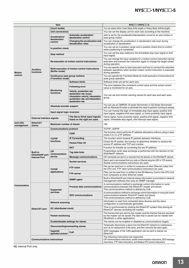
Motion control
Auxiliary functions
Count modes You can select either Linear Mode (finite length) or Rotary Mode (infinite length).Unit conversions You can set the display unit for each axis according to the machine.
Acceleration/ deceleration control
Automatic acceleration/deceleration control
Jerk is set for the acceleration/deceleration curve for an axis motion or axes group motion.
Changing the acceleration and deceleration rates
You can change the acceleration or deceleration rate even during acceleration or deceleration.
In-position check You can set an in-position range and in-position check time to confirm when positioning is completed.
Stop method You can set the stop method to the immediate stop input signal or limit input signal.
Re-execution of motion control instructionsYou can change the input variables for a motion control instruction during execution and execute the instruction again to change the target values during operation.
Multi-execution of motion control instructions (Buffer mode)
You can specify when to start execution and how to connect the velocities between operations when another motion control instruction is executed during operation.
Continuous axes group motions(Transition mode)
You can specify the Transition Mode for multi-execution of instructions for axes group operation.
Monitoring functions
Software limits Software limits are set for each axis.
Following error The error between the command current value and the actual current value is monitored for an axis.
Velocity, acceleration rate, deceleration rate, torque, interpolation velocity, interpolation acceleration rate, and interpolation deceleration rate
You can set and monitor warning values for each axis and each axes group.
Absolute encoder support You can use an OMRON 1S-series Servomotor or G5-Series Servomotor with an Absolute Encoder to eliminate the need to perform homing at startup.
Input signal logic inversion You can inverse the logic of immediate stop input signal, positive limit input signal, negative limit input signal, or home proximity input signal.
External interface signals The Servo Drive input signals listed on the right are used.
Home signal, home proximity signal, positive limit signal, negative limit signal, immediate stop signal, and interrupt input signal.
Unit (I/O) management
EtherCAT slaves Maximum number of slaves 192
Communications
Built-in EtherNet/IP portInternal Port
Communications protocol TCP/IP, UDP/IP
TCP/IP functions
CIDR The function which performs IP address allocations without using a class (class A to C) of IP address.
IP Forwarding The function which forward IP packets between interfaces.
Packet Filter *2 Check the IP packet, the function to determine whether to receive the source IP address and TCP port number.
NAT Function for transfer by converting the two IP address.
CIP communications service
Tag data links Programless cyclic data exchange is performed with the devices on the EtherNet/IP network.
Message communications CIP commands are sent to or received from the devices on the EtherNet/IP network.
TCP/IP applications
Socket services Data is sent to and received from any node on Ethernet using the UDP or TCP protocol.Socket communications instructions are used.
FTP client File can be read from or written to computers at other Ethernet nodes from the CPU Unit. FTP client communications instructions are used.
FTP server Files can be read from or written to the SD Memory Card in the CPU Unit from computers at other Ethernet nodes.
SNMP agent Built-in EtherNet/IP port internal status information is provided to network management software that uses an SNMP manager.
EtherCAT port
Supported services
Process data communicationsA communications method to exchange control information in cyclic communications between the EtherCAT master and slaves. This communications method is defined by CoE.
SDO communicationsA communications method to exchange control information in noncyclic event communications between EtherCAT master and slaves.This communications method is defined by CoE.
Network scanning Information is read from connected slave devices and the slave configuration is automatically generated.
DC (distributed clock) Time is synchronized by sharing the EtherCAT system time among all EtherCAT devices (including the master).
Packet monitoringThe frames that are sent by the master and the frames that are received by the master can be saved.The data that is saved can be viewed with WireShark or other applications.
Enable/disable settings for slaves The slaves can be enabled or disabled as communications targets.
Disconnecting/connecting slaves Temporarily disconnects a slave from the EtherCAT network for maintenance, such as for replacement of the slave, and then connects the slave again.
Supported application protocol CoE SDO messages of the CAN application can be sent to slaves via
EtherCAT.
Communications instructionsThe following instructions are supported.CIP communications instructions, socket communications instructions, SDO message instructions, FTP client instructions, and Modbus RTU protcol instructions.
Item NY5@@-1/NY5@@-5
*2. Internal Port only.
NY5@@-1/NY5@@-5
14
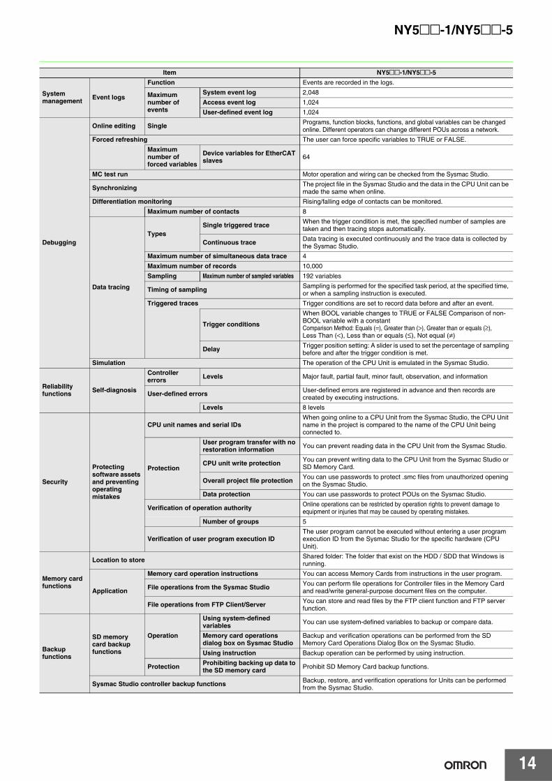
System management Event logs
Function Events are recorded in the logs.
Maximum number of events
System event log 2,048
Access event log 1,024User-defined event log 1,024
Debugging
Online editing Single Programs, function blocks, functions, and global variables can be changed online. Different operators can change different POUs across a network.
Forced refreshing The user can force specific variables to TRUE or FALSE.Maximum number of forced variables
Device variables for EtherCAT slaves 64
MC test run Motor operation and wiring can be checked from the Sysmac Studio.
Synchronizing The project file in the Sysmac Studio and the data in the CPU Unit can be made the same when online.
Differentiation monitoring Rising/falling edge of contacts can be monitored.
Maximum number of contacts 8
Data tracing
TypesSingle triggered trace When the trigger condition is met, the specified number of samples are
taken and then tracing stops automatically.
Continuous trace Data tracing is executed continuously and the trace data is collected by the Sysmac Studio.
Maximum number of simultaneous data trace 4
Maximum number of records 10,000Sampling Maximum number of sampled variables 192 variables
Timing of sampling Sampling is performed for the specified task period, at the specified time, or when a sampling instruction is executed.
Triggered traces Trigger conditions are set to record data before and after an event.
Trigger conditions
When BOOL variable changes to TRUE or FALSE Comparison of non-BOOL variable with a constantComparison Method: Equals (=), Greater than (>), Greater than or equals (≥),Less Than (<), Less than or equals (≤), Not equal (≠)
Delay Trigger position setting: A slider is used to set the percentage of sampling before and after the trigger condition is met.
Simulation The operation of the CPU Unit is emulated in the Sysmac Studio.
Reliability functions Self-diagnosis
Controller errors Levels Major fault, partial fault, minor fault, observation, and information
User-defined errors User-defined errors are registered in advance and then records are created by executing instructions.
Levels 8 levels
Security
Protecting software assets and preventing operating mistakes
CPU unit names and serial IDsWhen going online to a CPU Unit from the Sysmac Studio, the CPU Unit name in the project is compared to the name of the CPU Unit being connected to.
Protection
User program transfer with no restoration information You can prevent reading data in the CPU Unit from the Sysmac Studio.
CPU unit write protection You can prevent writing data to the CPU Unit from the Sysmac Studio or SD Memory Card.
Overall project file protection You can use passwords to protect .smc files from unauthorized opening on the Sysmac Studio.
Data protection You can use passwords to protect POUs on the Sysmac Studio.
Verification of operation authority Online operations can be restricted by operation rights to prevent damage to equipment or injuries that may be caused by operating mistakes.
Number of groups 5
Verification of user program execution IDThe user program cannot be executed without entering a user program execution ID from the Sysmac Studio for the specific hardware (CPU Unit).
Memory card functions
Location to store Shared folder: The folder that exist on the HDD / SDD that Windows is running.
Application
Memory card operation instructions You can access Memory Cards from instructions in the user program.
File operations from the Sysmac Studio You can perform file operations for Controller files in the Memory Card and read/write general-purpose document files on the computer.
File operations from FTP Client/Server You can store and read files by the FTP client function and FTP server function.
Backup functions
SD memory card backup functions
Operation
Using system-defined variables You can use system-defined variables to backup or compare data.
Memory card operations dialog box on Sysmac Studio
Backup and verification operations can be performed from the SD Memory Card Operations Dialog Box on the Sysmac Studio.
Using instruction Backup operation can be performed by using instruction.
Protection Prohibiting backing up data to the SD memory card Prohibit SD Memory Card backup functions.
Sysmac Studio controller backup functions Backup, restore, and verification operations for Units can be performed from the Sysmac Studio.
Item NY5@@-1/NY5@@-5
15
NY5@@-1/NY5@@-5
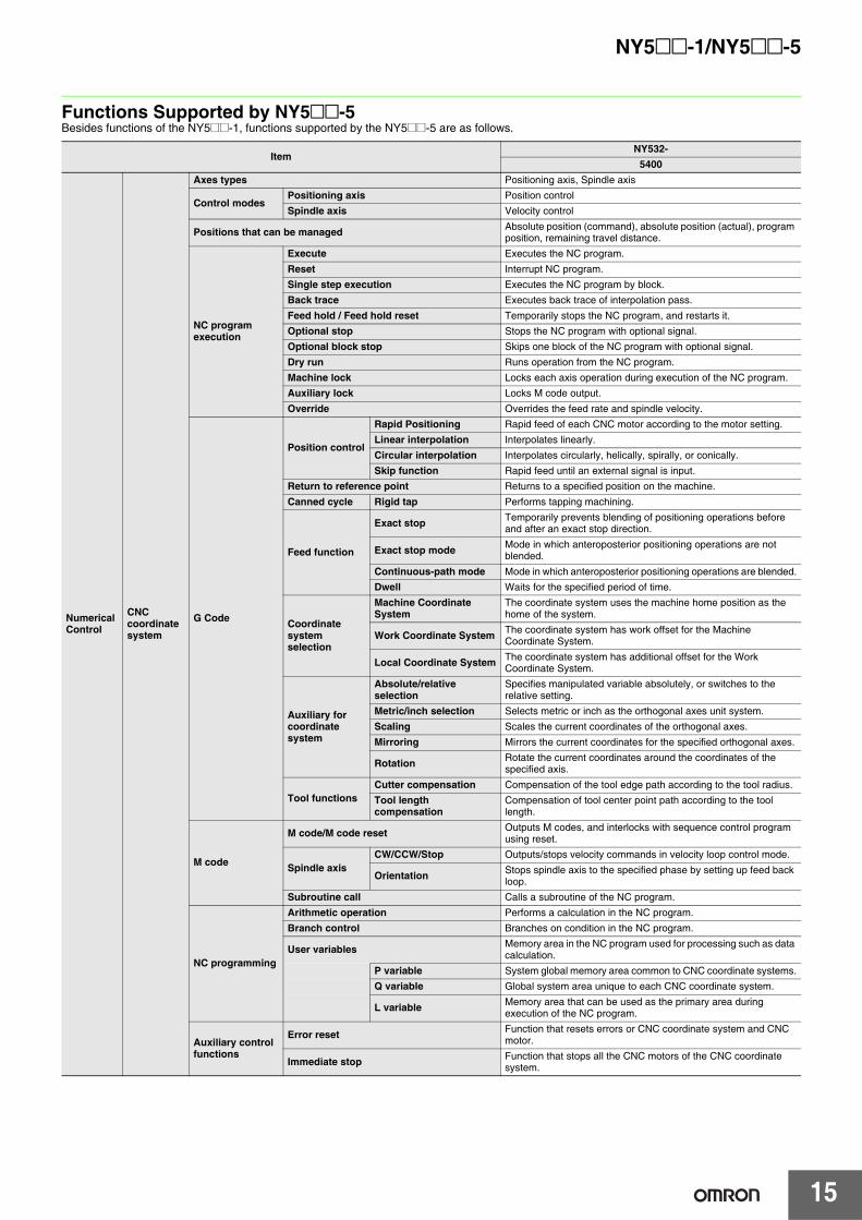
Functions Supported by NY5@@-5Besides functions of the NY5@@-1, functions supported by the NY5@@-5 are as follows.
ItemNY532-
5400
Numerical Control
CNC coordinate system
Axes types Positioning axis, Spindle axis
Control modesPositioning axis Position controlSpindle axis Velocity control
Positions that can be managed Absolute position (command), absolute position (actual), program position, remaining travel distance.
NC program execution
Execute Executes the NC program.
Reset Interrupt NC program.Single step execution Executes the NC program by block.Back trace Executes back trace of interpolation pass.
Feed hold / Feed hold reset Temporarily stops the NC program, and restarts it.Optional stop Stops the NC program with optional signal.Optional block stop Skips one block of the NC program with optional signal.
Dry run Runs operation from the NC program.Machine lock Locks each axis operation during execution of the NC program.Auxiliary lock Locks M code output.
Override Overrides the feed rate and spindle velocity.
G Code
Position control
Rapid Positioning Rapid feed of each CNC motor according to the motor setting.Linear interpolation Interpolates linearly.
Circular interpolation Interpolates circularly, helically, spirally, or conically.Skip function Rapid feed until an external signal is input.
Return to reference point Returns to a specified position on the machine.
Canned cycle Rigid tap Performs tapping machining.
Feed function
Exact stop Temporarily prevents blending of positioning operations before and after an exact stop direction.
Exact stop mode Mode in which anteroposterior positioning operations are not blended.
Continuous-path mode Mode in which anteroposterior positioning operations are blended.Dwell Waits for the specified period of time.
Coordinate system selection
Machine Coordinate System
The coordinate system uses the machine home position as the home of the system.
Work Coordinate System The coordinate system has work offset for the Machine Coordinate System.
Local Coordinate System The coordinate system has additional offset for the Work Coordinate System.
Auxiliary forcoordinatesystem
Absolute/relative selection
Specifies manipulated variable absolutely, or switches to the relative setting.
Metric/inch selection Selects metric or inch as the orthogonal axes unit system.Scaling Scales the current coordinates of the orthogonal axes.
Mirroring Mirrors the current coordinates for the specified orthogonal axes.
Rotation Rotate the current coordinates around the coordinates of the specified axis.
Tool functionsCutter compensation Compensation of the tool edge path according to the tool radius.Tool length compensation
Compensation of tool center point path according to the tool length.
M code
M code/M code reset Outputs M codes, and interlocks with sequence control program using reset.
Spindle axis CW/CCW/Stop Outputs/stops velocity commands in velocity loop control mode.
Orientation Stops spindle axis to the specified phase by setting up feed back loop.
Subroutine call Calls a subroutine of the NC program.
NC programming
Arithmetic operation Performs a calculation in the NC program.Branch control Branches on condition in the NC program.
User variables Memory area in the NC program used for processing such as data calculation.
P variable System global memory area common to CNC coordinate systems.Q variable Global system area unique to each CNC coordinate system.
L variable Memory area that can be used as the primary area during execution of the NC program.
Auxiliary control functions
Error reset Function that resets errors or CNC coordinate system and CNC motor.
Immediate stop Function that stops all the CNC motors of the CNC coordinate system.
16
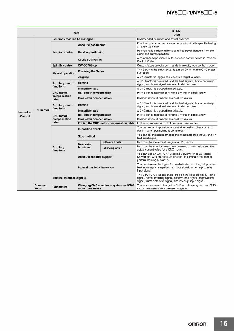
NY5@@-1/NY5@@-5
Numerical Control
CNC motor
Positions that can be managed Commanded positions and actual positions.
Position control
Absolute positioning Positioning is performed for a target position that is specified using an absolute value.
Relative positioning Positioning is performed for a specified travel distance from the command current position.
Cyclic positioning A commanded position is output at each control period in Position Control Mode.
Spindle control CW/CCW/Stop Outputs/stops velocity commands in velocity loop control mode.
Manual operationPowering the Servo The Servo in the servo driver is turned ON to enable CNC motor
operation.
Jogging A CNC motor is jogged at a specified target velocity.
Auxiliary control functions
Homing A CNC motor is operated, and the limit signals, home proximity signal, and home signal are used to define home.
Immediate stop A CNC motor is stopped immediately.CNC motor compensation table
Ball screw compensation Pitch error compensation for one-dimensional ball screw.
Cross-axis compensation Compensation of one-dimensional cross-axis.
Auxiliary control functions
Homing A CNC motor is operated, and the limit signals, home proximity signal, and home signal are used to define home.
Immediate stop A CNC motor is stopped immediately.
CNC motor compensation table
Ball screw compensation Pitch error compensation for one-dimensional ball screw.Cross-axis compensation Compensation of one-dimensional cross-axis.
Editing the CNC motor compensation table Edit using sequence control program (Read/write).
Auxiliary functions
In-position check You can set an in-position range and in-position check time to confirm when positioning is completed.
Stop method You can set the stop method to the immediate stop input signal or limit input signal.
Monitoring functions
Software limits Monitors the movement range of a CNC motor.
Following error Monitors the error between the command current value and the actual current value for a CNC motor.
Absolute encoder supportYou can use an OMRON 1S-series Servomotor or G5-series Servomotor with an Absolute Encoder to eliminate the need to perform homing at startup.
Input signal logic inversionYou can inverse the logic of immediate stop input signal, positive limit input signal, negative limit input signal, or home proximity input signal.
External interface signalsThe Servo Drive input signals listed on the right are used. Home signal, home proximity signal, positive limit signal, negative limit signal, immediate stop signal, and interrupt input signal.
Common items Parameters Changing CNC coordinate system and CNC
motor parametersYou can access and change the CNC coordinate system and CNC motor parameters from the user program.
ItemNY532-
5400
17
NY5@@-1/NY5@@-5
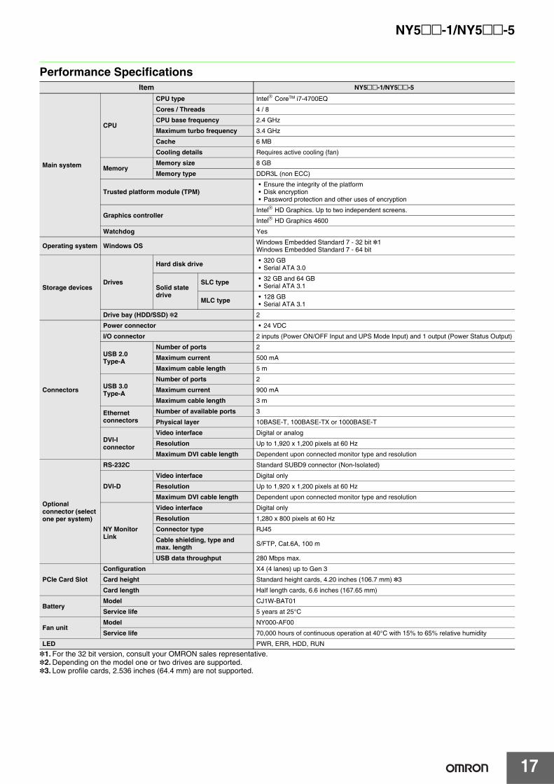
Performance Specifications
*1. For the 32 bit version, consult your OMRON sales representative.*2. Depending on the model one or two drives are supported.*3. Low profile cards, 2.536 inches (64.4 mm) are not supported.
Item NY5@@-1/NY5@@-5
Main system
CPU
CPU type Intel CoreTM i7-4700EQ
Cores / Threads 4 / 8
CPU base frequency 2.4 GHz
Maximum turbo frequency 3.4 GHz
Cache 6 MB
Cooling details Requires active cooling (fan)
MemoryMemory size 8 GB
Memory type DDR3L (non ECC)
Trusted platform module (TPM)• Ensure the integrity of the platform• Disk encryption• Password protection and other uses of encryption
Graphics controller Intel HD Graphics. Up to two independent screens.
Intel HD Graphics 4600
Watchdog Yes
Operating system Windows OS Windows Embedded Standard 7 - 32 bit *1Windows Embedded Standard 7 - 64 bit
Storage devicesDrives
Hard disk drive • 320 GB• Serial ATA 3.0
Solid state drive
SLC type • 32 GB and 64 GB• Serial ATA 3.1
MLC type • 128 GB• Serial ATA 3.1
Drive bay (HDD/SSD) *2 2
Connectors
Power connector • 24 VDC
I/O connector 2 inputs (Power ON/OFF Input and UPS Mode Input) and 1 output (Power Status Output)
USB 2.0 Type-A
Number of ports 2
Maximum current 500 mA
Maximum cable length 5 m
USB 3.0 Type-A
Number of ports 2
Maximum current 900 mA
Maximum cable length 3 m
Ethernet connectors
Number of available ports 3
Physical layer 10BASE-T, 100BASE-TX or 1000BASE-T
DVI-I connector
Video interface Digital or analog
Resolution Up to 1,920 x 1,200 pixels at 60 Hz
Maximum DVI cable length Dependent upon connected monitor type and resolution
Optional connector (select one per system)
RS-232C Standard SUBD9 connector (Non-Isolated)
DVI-D
Video interface Digital only
Resolution Up to 1,920 x 1,200 pixels at 60 Hz
Maximum DVI cable length Dependent upon connected monitor type and resolution
NY Monitor Link
Video interface Digital only
Resolution 1,280 x 800 pixels at 60 Hz
Connector type RJ45
Cable shielding, type and max. length S/FTP, Cat.6A, 100 m
USB data throughput 280 Mbps max.
PCIe Card SlotConfiguration X4 (4 lanes) up to Gen 3
Card height Standard height cards, 4.20 inches (106.7 mm) *3
Card length Half length cards, 6.6 inches (167.65 mm)
BatteryModel CJ1W-BAT01
Service life 5 years at 25°C
Fan unitModel NY000-AF00
Service life 70,000 hours of continuous operation at 40°C with 15% to 65% relative humidity
LED PWR, ERR, HDD, RUN
18
NY5@@-1/NY5@@-5
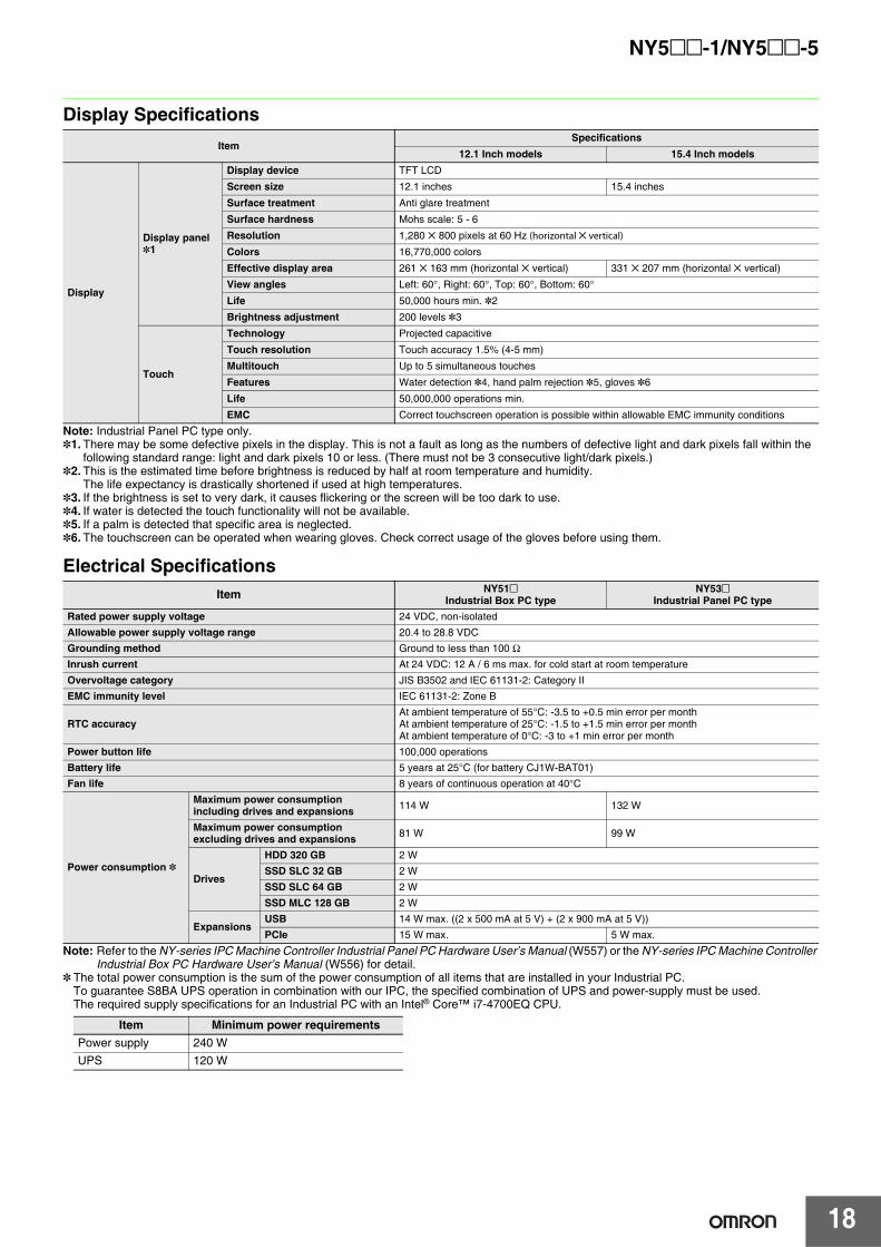
Display Specifications
Note: Industrial Panel PC type only.*1. There may be some defective pixels in the display. This is not a fault as long as the numbers of defective light and dark pixels fall within the
following standard range: light and dark pixels 10 or less. (There must not be 3 consecutive light/dark pixels.)*2. This is the estimated time before brightness is reduced by half at room temperature and humidity.
The life expectancy is drastically shortened if used at high temperatures.*3. If the brightness is set to very dark, it causes flickering or the screen will be too dark to use.*4. If water is detected the touch functionality will not be available.*5. If a palm is detected that specific area is neglected.*6. The touchscreen can be operated when wearing gloves. Check correct usage of the gloves before using them.
Electrical Specifications
Note: Refer to the NY-series IPC Machine Controller Industrial Panel PC Hardware User’s Manual (W557) or the NY-series IPC Machine Controller Industrial Box PC Hardware User’s Manual (W556) for detail.
* The total power consumption is the sum of the power consumption of all items that are installed in your Industrial PC.To guarantee S8BA UPS operation in combination with our IPC, the specified combination of UPS and power-supply must be used.The required supply specifications for an Industrial PC with an Intel® Core™ i7-4700EQ CPU.
ItemSpecifications
12.1 Inch models 15.4 Inch models
Display
Display panel *1
Display device TFT LCD
Screen size 12.1 inches 15.4 inches
Surface treatment Anti glare treatment
Surface hardness Mohs scale: 5 - 6
Resolution 1,280 ✕ 800 pixels at 60 Hz (horizontal ✕ vertical)
Colors 16,770,000 colors
Effective display area 261 ✕ 163 mm (horizontal ✕ vertical) 331 ✕ 207 mm (horizontal ✕ vertical)
View angles Left: 60°, Right: 60°, Top: 60°, Bottom: 60°
Life 50,000 hours min. *2
Brightness adjustment 200 levels *3
Touch
Technology Projected capacitive
Touch resolution Touch accuracy 1.5% (4-5 mm)
Multitouch Up to 5 simultaneous touches
Features Water detection *4, hand palm rejection *5, gloves *6
Life 50,000,000 operations min.
EMC Correct touchscreen operation is possible within allowable EMC immunity conditions
Item NY51@Industrial Box PC type
NY53@Industrial Panel PC type
Rated power supply voltage 24 VDC, non-isolated
Allowable power supply voltage range 20.4 to 28.8 VDC
Grounding method Ground to less than 100 ΩInrush current At 24 VDC: 12 A / 6 ms max. for cold start at room temperature
Overvoltage category JIS B3502 and IEC 61131-2: Category II
EMC immunity level IEC 61131-2: Zone B
RTC accuracyAt ambient temperature of 55°C: -3.5 to +0.5 min error per monthAt ambient temperature of 25°C: -1.5 to +1.5 min error per monthAt ambient temperature of 0°C: -3 to +1 min error per month
Power button life 100,000 operations
Battery life 5 years at 25°C (for battery CJ1W-BAT01)
Fan life 8 years of continuous operation at 40°C
Power consumption *
Maximum power consumption including drives and expansions 114 W 132 W
Maximum power consumption excluding drives and expansions 81 W 99 W
Drives
HDD 320 GB 2 W
SSD SLC 32 GB 2 W
SSD SLC 64 GB 2 W
SSD MLC 128 GB 2 W
ExpansionsUSB 14 W max. ((2 x 500 mA at 5 V) + (2 x 900 mA at 5 V))
PCIe 15 W max. 5 W max.
Item Minimum power requirementsPower supply 240 WUPS 120 W
19
NY5@@-1/NY5@@-5
Environmental Specifications
*1. The allowed ambient operating temperature and ambient humidity depend on product type, CPU type, mounting orientation, and storage device type.*2. Vibration resistance depends on the Box PC's mounting orientation and storage device type.
*3. A Panel PC with one or more HDD storage devices should not be used in applications subject to vibration.Examples of applications subject to vibration:• AGV (Automated Guided Vehicles) • Tableting machine• Rail vehicle • Connector pin assembling machine• Stacker crane • Bending machine• Elevator
Ensure your Panel PC with HDD does not vibrate. When in doubt use a Panel PC with SSD storage devices.*4. The Panel PC may not operate properly in locations subjected to oil splashes for extended periods of time. (Industrial Panel PC type only)*5. Refer to the OMRON website (www.ia.omron.com) or contact your OMRON representative for the most recent applicable standards for each model.
Storage Device Specifications
*1. For a Panel PC with an HDD: this device can only be installed in a vibration free environment only. *2. Powered-ON hours include sleep and standby modes.*3. Operation includes seeking, writing, and reading functions.
ItemSpecifications
Industrial Box PC Industrial Panel PC
Operation environment
Ambient operating temperature *1 0 to 55°C
Ambient storage temperature *1 -20 to 70°C
Ambient operating humidity *1 10% to 90% with no condensation
Ambient storage humidity *1 10% to 90% with no condensation
Operating atmosphere No corrosive gases
Altitude 2,000 m max.
Noise resistance (during operation) Conforms to IEC61000-4-4, 2 kV (power lines)
Vibration resistance (during operation)
Conforms to IEC 60068-2-6.• For a Box PC with an SSD:
5 to 8.4 Hz with 3.5 mm single amplitude and 8.4 to 150 Hz with 9.8 m/s2 for 10 times each in X, Y and Z directions.
• For a Box PC with a HDD the vibration resistance depends on the mounting orientation *2.
The vibration resistance depends on the storage device(s):• For a Panel PC with only SSD storage devices:
5 to 8.4Hz with 3.5 mm single amplitude and 8.4 to 150 Hz with 9.8 m/s2 for 10 times each in X, Y and Z directions. Conforms to IEC 60068-2-6.
• For a Panel PC with one or more HDD storage devices the Panel PC must be installed in a vibration free environment. *3
Shock resistance (during operation)
Conforms to IEC 60068-2-27.147 m/s2, 3 times in each X, Y and Z directions
Installation method Book mount, Wall mount Mount on panel
Degree of protection *4 − Front of Monitor: IP65
Pollution degree 2 or less: Conforms to JIS B3502 and IEC 61131-2.
Applicable standards *5 EU Directives: EMC Directive 2014/30/EU (EN 61131-2) and RoHS DirectiveKC Registration, RCM, cULus
Item SpecificationsModel NY000-AS00 NY000-AS01 NY000-AS02 NY000-AH00 *1
Capacity 32 GB 64 GB 128 GB 320 GB
Type SSD (SLC) SSD (MLC) HDD
S.M.A.R.T. support Yes
Rotation speed − 5,400 r/min
Interface Serial ATA 3.1 Serial ATA 3.0
Sustained standard read speed Up to 160 MB/s Up to 430 MB/s −Sustained standard write speed Up to 150 MB/s Up to 190 MB/s −Operating temperature 0 to 70°C 5 to 55°C
Operating humidity 10% to 95% (with no condensation) • 10% to 95% (with no condensation)• 29°C wet-bulb temperature max.
Storage temperature -40 to 100°C -40 to 65°C
Storage humidity 10% to 95% (with no condensation) • 8% to 90% (with no condensation)• 40°C wet-bulb temperature max.
Life 1,500 TB written / 11 years at a daily workload of 350 GB
3,000 TB written / 23 years at a daily workload of 350 GB
114 TB written / 3 years at a daily workload of 100 GB
Approximately 5 years or 20,000 powered-ON hours (whichever comes first) under the following conditions:• 25°C at 101.3 kPa• Less than 333 powered-ON hours/
month *2• Less than 20% operation while
powered-ON *3• Less than 1.30 x 10⁶ seeks/month
Mounting Orientation SSD HDD
Book9.8 m/s2
2.5 m/s2
Wall 4.9 m/s2
NY5@@-1/NY5@@-5
20
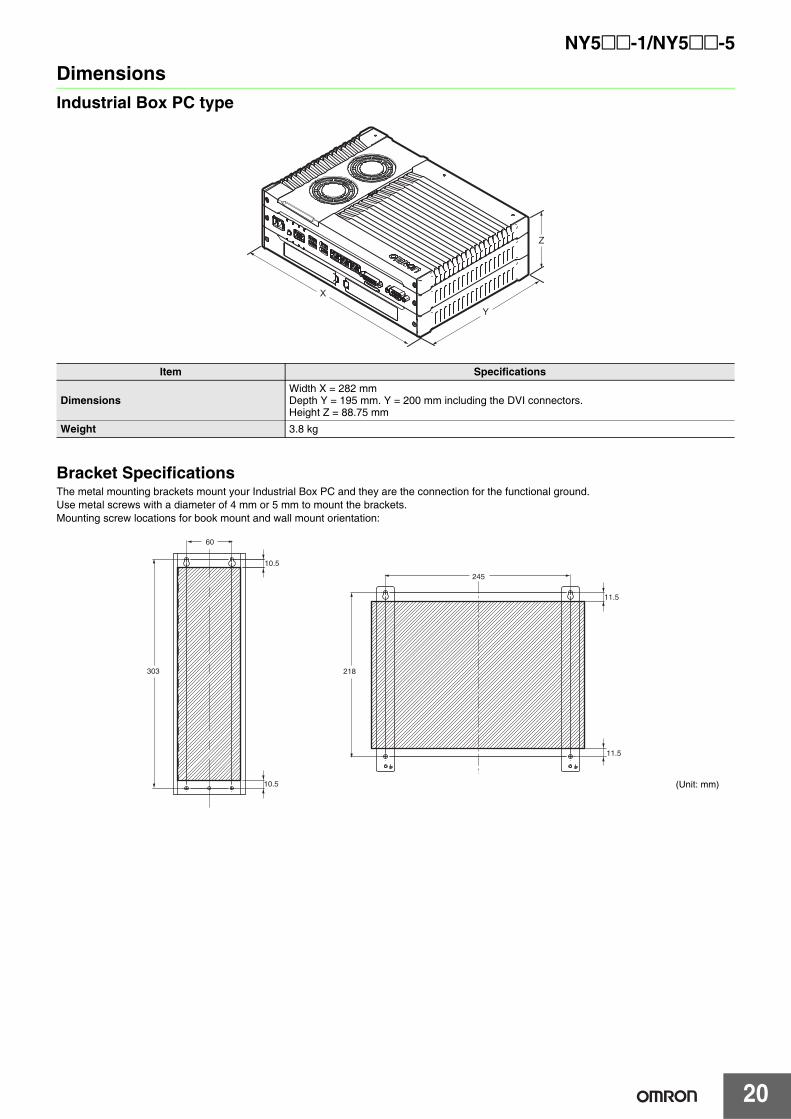
DimensionsIndustrial Box PC type
Bracket SpecificationsThe metal mounting brackets mount your Industrial Box PC and they are the connection for the functional ground.Use metal screws with a diameter of 4 mm or 5 mm to mount the brackets.Mounting screw locations for book mount and wall mount orientation:
Item Specifications
DimensionsWidth X = 282 mmDepth Y = 195 mm. Y = 200 mm including the DVI connectors.Height Z = 88.75 mm
Weight 3.8 kg
Y
Z
X
10.5
10.5
60
303
11.5
11.5
245
218
(Unit: mm)
21
NY5@@-1/NY5@@-5
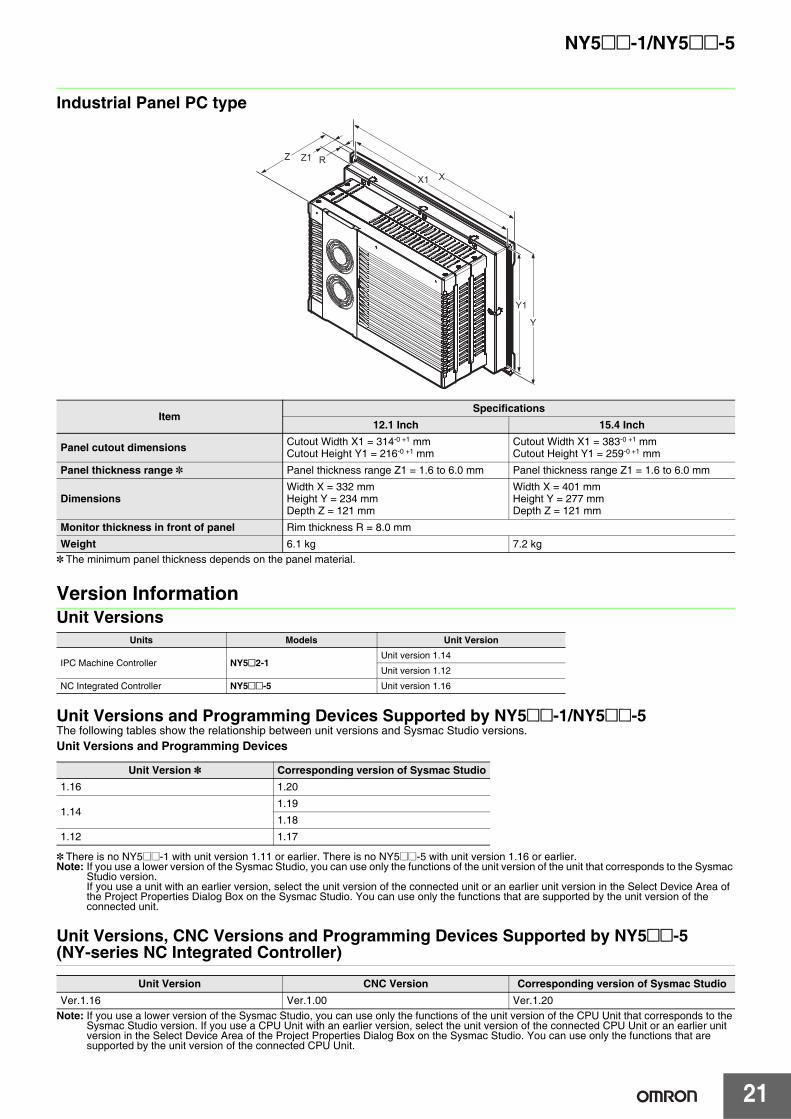
Industrial Panel PC type
* The minimum panel thickness depends on the panel material.
Version InformationUnit Versions
Unit Versions and Programming Devices Supported by NY5@@-1/NY5@@-5The following tables show the relationship between unit versions and Sysmac Studio versions.Unit Versions and Programming Devices
* There is no NY5@@-1 with unit version 1.11 or earlier. There is no NY5@@-5 with unit version 1.16 or earlier.Note: If you use a lower version of the Sysmac Studio, you can use only the functions of the unit version of the unit that corresponds to the Sysmac
Studio version.If you use a unit with an earlier version, select the unit version of the connected unit or an earlier unit version in the Select Device Area of the Project Properties Dialog Box on the Sysmac Studio. You can use only the functions that are supported by the unit version of the connected unit.
Unit Versions, CNC Versions and Programming Devices Supported by NY5@@-5(NY-series NC Integrated Controller)
Note: If you use a lower version of the Sysmac Studio, you can use only the functions of the unit version of the CPU Unit that corresponds to the Sysmac Studio version. If you use a CPU Unit with an earlier version, select the unit version of the connected CPU Unit or an earlier unit version in the Select Device Area of the Project Properties Dialog Box on the Sysmac Studio. You can use only the functions that are supported by the unit version of the connected CPU Unit.
ItemSpecifications
12.1 Inch 15.4 Inch
Panel cutout dimensions Cutout Width X1 = 314-0 +1 mmCutout Height Y1 = 216-0 +1 mm
Cutout Width X1 = 383-0 +1 mmCutout Height Y1 = 259-0 +1 mm
Panel thickness range * Panel thickness range Z1 = 1.6 to 6.0 mm Panel thickness range Z1 = 1.6 to 6.0 mm
DimensionsWidth X = 332 mmHeight Y = 234 mmDepth Z = 121 mm
Width X = 401 mmHeight Y = 277 mmDepth Z = 121 mm
Monitor thickness in front of panel Rim thickness R = 8.0 mm
Weight 6.1 kg 7.2 kg
Units Models Unit Version
IPC Machine Controller NY5@2-1Unit version 1.14
Unit version 1.12
NC Integrated Controller NY5@@-5 Unit version 1.16
Unit Version * Corresponding version of Sysmac Studio1.16 1.20
1.141.19
1.18
1.12 1.17
Unit Version CNC Version Corresponding version of Sysmac StudioVer.1.16 Ver.1.00 Ver.1.20
Z
Y1
Z1
Y
X1 X
R
NY5@@-1/NY5@@-5
22
Related ManualsRefer to the Related Manuals in the data sheet of the NY-series Industrial Box PC or NY-series Industrial Panel PC for the Related Manuals.
Manual name Cat. No. Model numbers Application Description
NY-seriesIPC Machine ControllerIndustrial Panel PCHardware User’s Manual
W557 NY532-@@@@
Learning the basic specifications of the NY-series Industrial Panel PCs, including introductory information, designing, installation, and maintenance. Mainly hardware information is provided.
An introduction to the entire NY-series system is provided along with the following information on the Industrial Panel PC.• Features and system configuration• Introduction• Part names and functions• General specifications• Installation and wiring• Maintenance and inspection
NY-seriesIPC Machine ControllerIndustrial Box PCHardware User’s Manual
W556 NY512-@@@@
Learning the basic specifications of the NY-series Industrial Box PCs, including introductory information, designing, installation, and maintenance. Mainly hardware information is provided.
An introduction to the entire NY-series system is provided along with the following information on the Industrial Box PC.• Features and system configuration• Introduction• Part names and functions• General specifications• Installation and wiring• Maintenance and inspection
NY-seriesIPC Machine ControllerIndustrial Panel PC / Industrial Box PCSetup User's Manual
W568 NY532-@@@@NY512-@@@@
Learning the initial settings of the NY-series Industrial PCs and preparations to use Controllers.
The following information is provided on an introduction to the entire NY-series system. • Two OS systems• Initial settings• Industrial PC Support Utility• NYCompolet• Industrial PC API• Backup and recovery
NY-seriesIPC Machine ControllerIndustrial Panel PC / Industrial Box PCSoftware User’s Manual
W558 NY532-@@@@NY512-@@@@
Learning how to program and set up the Controller functions of an NY-series Industrial PC.
The following information is provided on NY-series Machine Automation Control Software.• Controller operation• Controller features• Controller settings• Programming based on IEC 61131-3 language
specifications
NY-series Instructions Reference Manual W560 NY532-@@@@
NY512-@@@@
Learning detailed specifications on the basic instructions of an NY-series Industrial PC.
The instructions in the instruction set (IEC 61131-3 specifications) are described.
NY-seriesIPC Machine ControllerIndustrial Panel PC / Industrial Box PCMotion Control User's Manual
W559 NY532-@@@@NY512-@@@@
Learning about motion control settings and programming conceptsof an NY-series Industrial PC.
The settings and operation of the Controller and programming concepts for motion control are described.
NY-seriesMotion Control InstructionsReference Manual
W561 NY532-@@@@NY512-@@@@
Learning about the specifications of the motion control instructions of an NY-series Industrial PC.
The motion control instructions are described.
NY-seriesIPC Machine ControllerIndustrial Panel PC / Industrial Box PCBuilt-in EtherCAT® PortUser’s Manual
W562 NY532-@@@@NY512-@@@@
Using the built-in EtherCAT port in an NY-series Industrial PC
Information on the built-in EtherCAT port is provided. This manual provides an introduction and provides information on the configuration, features, and setup.
NY-seriesIPC Machine ControllerIndustrial Panel PC / Industrial Box PCBuilt-in EtherNet/IPTM PortUser’s Manual
W563 NY532-@@@@NY512-@@@@
Using the built-in EtherNet/ IP port in an NY-series Industrial PC.
Information on the built-in EtherNet/IP port is provided. Information is provided on the basic setup, tag data links, and other features.
NY-seriesTroubleshooting Manual W564 NY532-@@@@
NY512-@@@@
Learning about the errors that may be detected in an NY-series Industrial PC.
Concepts on managing errors that may be detected in an NY-series Controller and information on individual errors are described.
NJ/NY-Series NC Integrated Controller User's Manual O0300-E1 NJ501-5300
NY532-5400For numerical control with NJ/NY-series
Describes the numerical control function. When programming, use this manual together with the G Code Instructions Reference Manual (O0301-E1).
NJ/NY-Series NC Integrated Controller Instruction Reference Manual G code
O0301-E1 NJ501-5300NY532-5400
Learning about detailed specifications of the G code/M code instructions.
This section describes G code/M code instructions in detail. When programming, use this manual together with the User’s Manual (O0301-E1).
CNC Operator Operation Manual O0302-E1 SYSMAC-RTNC0@@@D
Learning the overview of CNC Operator and how to use it.
Describes the CNC Operator, installation procedure, basic operation, connection operation, and operating procedures for main functions.
Sysmac Studio Version 1Operation Manual W504 SYSMAC-SE2@@@
Learning about the operating procedures and functions of the Sysmac Studio.
Describes the operating procedures of the Sysmac Studio.
UPS S8BAUser's Manual U702 S8BA
Learning the information that is necessary to use the Uninterruptible Power Supply (UPS) Unit.
An introduction to the UPS is provided along with the following information:• Overview• Preparation• Installation and Connection• Check and Start Operation• Maintenance and Inspection• Shutdown Processing• I/O Signal Functions• Troubleshooting
Terms and Conditions Agreement Read and understand this catalog. Please read and understand this catalog before purchasing the products. Please consult your OMRON representative if you have any questions or comments. Warranties. (a) Exclusive Warranty. Omron’s exclusive warranty is that the Products will be free from defects in materials and workmanship for a period of twelve months from the date of sale by Omron (or such other period expressed in writing by Omron). Omron disclaims all other warranties, express or implied. (b) Limitations. OMRON MAKES NO WARRANTY OR REPRESENTATION, EXPRESS OR IMPLIED, ABOUT NON-INFRINGEMENT, MERCHANTABILITY OR FITNESS FOR A PARTICULAR PURPOSE OF THE PRODUCTS. BUYER ACKNOWLEDGES THAT IT ALONE HAS DETERMINED THAT THE PRODUCTS WILL SUITABLY MEET THE REQUIREMENTS OF THEIR INTENDED USE. Omron further disclaims all warranties and responsibility of any type for claims or expenses based on infringement by the Products or otherwise of any intellectual property right. (c) Buyer Remedy. Omron’s sole obligation hereunder shall be, at Omron’s election, to (i) replace (in the form originally shipped with Buyer responsible for labor charges for removal or replacement thereof) the non-complying Product, (ii) repair the non-complying Product, or (iii) repay or credit Buyer an amount equal to the purchase price of the non-complying Product; provided that in no event shall Omron be responsible for warranty, repair, indemnity or any other claims or expenses regarding the Products unless Omron’s analysis confirms that the Products were properly handled, stored, installed and maintained and not subject to contamination, abuse, misuse or inappropriate modification. Return of any Products by Buyer must be approved in writing by Omron before shipment. Omron Companies shall not be liable for the suitability or unsuitability or the results from the use of Products in combination with any electrical or electronic components, circuits, system assemblies or any other materials or substances or environments. Any advice, recommendations or information given orally or in writing, are not to be construed as an amendment or addition to the above warranty. See http://www.omron.com/global/ or contact your Omron representative for published information. Limitation on Liability; Etc. OMRON COMPANIES SHALL NOT BE LIABLE FOR SPECIAL, INDIRECT, INCIDENTAL, OR CONSEQUENTIAL DAMAGES, LOSS OF PROFITS OR PRODUCTION OR COMMERCIAL LOSS IN ANY WAY CONNECTED WITH THE PRODUCTS, WHETHER SUCH CLAIM IS BASED IN CONTRACT, WARRANTY, NEGLIGENCE OR STRICT LIABILITY. Further, in no event shall liability of Omron Companies exceed the individual price of the Product on which liability is asserted. Suitability of Use. Omron Companies shall not be responsible for conformity with any standards, codes or regulations which apply to the combination of the Product in the Buyer’s application or use of the Product. At Buyer’s request, Omron will provide applicable third party certification documents identifying ratings and limitations of use which apply to the Product. This information by itself is not sufficient for a complete determination of the suitability of the Product in combination with the end product, machine, system, or other application or use. Buyer shall be solely responsible for determining appropriateness of the particular Product with respect to Buyer’s application, product or system. Buyer shall take application responsibility in all cases. NEVER USE THE PRODUCT FOR AN APPLICATION INVOLVING SERIOUS RISK TO LIFE OR PROPERTY OR IN LARGE QUANTITIES WITHOUT ENSURING THAT THE SYSTEM AS A WHOLE HAS BEEN DESIGNED TO ADDRESS THE RISKS, AND THAT THE OMRON PRODUCT(S) IS PROPERLY RATED AND INSTALLED FOR THE INTENDED USE WITHIN THE OVERALL EQUIPMENT OR SYSTEM. Programmable Products. Omron Companies shall not be responsible for the user’s programming of a programmable Product, or any consequence thereof. Performance Data. Data presented in Omron Company websites, catalogs and other materials is provided as a guide for the user in determining suitability and does not constitute a warranty. It may represent the result of Omron’s test conditions, and the user must correlate it to actual application requirements. Actual performance is subject to the Omron’s Warranty and Limitations of Liability. Change in Specifications. Product specifications and accessories may be changed at any time based on improvements and other reasons. It is our practice to change part numbers when published ratings or features are changed, or when significant construction changes are made. However, some specifications of the Product may be changed without any notice. When in doubt, special part numbers may be assigned to fix or establish key specifications for your application. Please consult with your Omron’s representative at any time to confirm actual specifications of purchased Product. Errors and Omissions. Information presented by Omron Companies has been checked and is believed to be accurate; however, no responsibility is assumed for clerical, typographical or proofreading errors or omissions.
2017.9
In the interest of product improvement, specifications are subject to change without notice.
OMRON Corporation Industrial Automation Company http://www.ia.omron.com/
(c)Copyright OMRON Corporation 2017 All Right Reserved.