Embed Size (px)
Citation preview
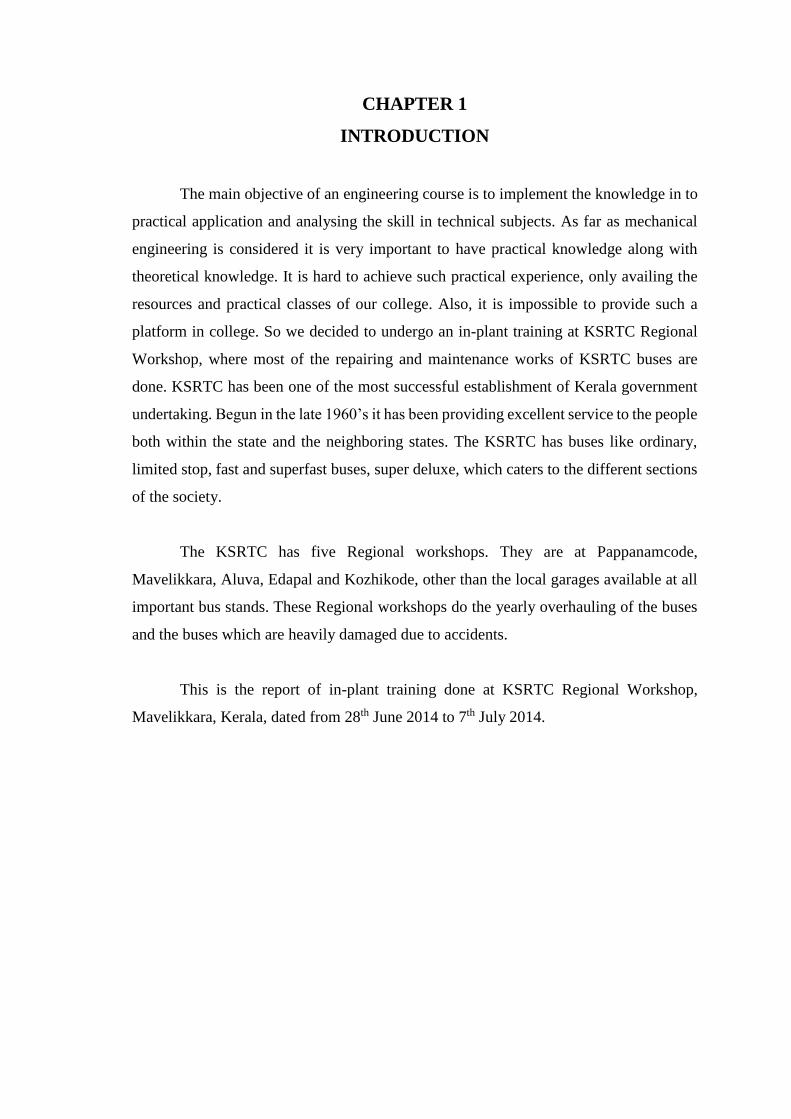
CHAPTER 1
INTRODUCTION
The main objective of an engineering course is to implement the knowledge in to
practical application and analysing the skill in technical subjects. As far as mechanical
engineering is considered it is very important to have practical knowledge along with
theoretical knowledge. It is hard to achieve such practical experience, only availing the
resources and practical classes of our college. Also, it is impossible to provide such a
platform in college. So we decided to undergo an in-plant training at KSRTC Regional
Workshop, where most of the repairing and maintenance works of KSRTC buses are
done. KSRTC has been one of the most successful establishment of Kerala government
undertaking. Begun in the late 1960’s it has been providing excellent service to the people
both within the state and the neighboring states. The KSRTC has buses like ordinary,
limited stop, fast and superfast buses, super deluxe, which caters to the different sections
of the society.
The KSRTC has five Regional workshops. They are at Pappanamcode,
Mavelikkara, Aluva, Edapal and Kozhikode, other than the local garages available at all
important bus stands. These Regional workshops do the yearly overhauling of the buses
and the buses which are heavily damaged due to accidents.
This is the report of in-plant training done at KSRTC Regional Workshop,
Mavelikkara, Kerala, dated from 28th June 2014 to 7th July 2014.
CHAPTER 2
MAINTENANCE SECTIONS
The regional workshop consists of different sections for the smooth and easy
maintenance of the buses. The different sections and their activities are explained below.
2.1 ENGINE ASSEMBLY SECTION
The internal combustion engine is an integral part of a vehicle in which
combustion of fuel {generally, fossil fuel} occurs with an oxidizer (usually air) in a
combustion chamber. In an internal combustion engine, the expansion of the high
pressure gases which are produced during the combustion process occurs. During this
process force is applied to components of the engine such as the pistons or turbine blades
or nozzle, and by moving it over a distance results in generation of useful mechanical
energy.
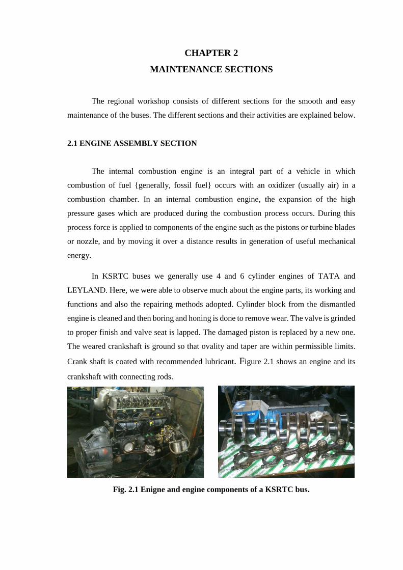
In KSRTC buses we generally use 4 and 6 cylinder engines of TATA and
LEYLAND. Here, we were able to observe much about the engine parts, its working and
functions and also the repairing methods adopted. Cylinder block from the dismantled
engine is cleaned and then boring and honing is done to remove wear. The valve is grinded
to proper finish and valve seat is lapped. The damaged piston is replaced by a new one.
The weared crankshaft is ground so that ovality and taper are within permissible limits.
Crank shaft is coated with recommended lubricant. Figure 2.1 shows an engine and its
crankshaft with connecting rods.
Fig. 2.1 Enigne and engine components of a KSRTC bus.
2.2 GEAR BOX SECTION
A machine consists of a power source and a transmission system, which provides
controlled application of power. Merriam-Webster defines transmission as an assembly
of parts including the speed-changing gears and the propeller shaft by which the power is
transmitted from an engine to a live axle. The most common use is in motor vehicles,
where the transmission adapts the output at the internal combustion engine to drive
wheels. Such engines need to operate at a relatively high rotational speed, which is
inappropriate for starting, stopping and slower travel. The transmission reduces the high
engine speed to the slower wheel speed, increasing torque in process.
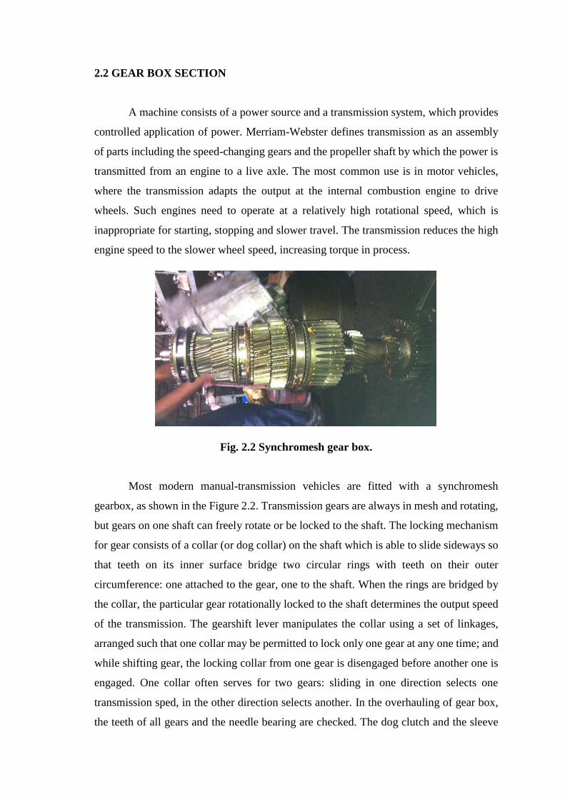
Fig. 2.2 Synchromesh gear box.
Most modern manual-transmission vehicles are fitted with a synchromesh
gearbox, as shown in the Figure 2.2. Transmission gears are always in mesh and rotating,
but gears on one shaft can freely rotate or be locked to the shaft. The locking mechanism
for gear consists of a collar (or dog collar) on the shaft which is able to slide sideways so
that teeth on its inner surface bridge two circular rings with teeth on their outer
circumference: one attached to the gear, one to the shaft. When the rings are bridged by
the collar, the particular gear rotationally locked to the shaft determines the output speed
of the transmission. The gearshift lever manipulates the collar using a set of linkages,
arranged such that one collar may be permitted to lock only one gear at any one time; and
while shifting gear, the locking collar from one gear is disengaged before another one is
engaged. One collar often serves for two gears: sliding in one direction selects one
transmission sped, in the other direction selects another. In the overhauling of gear box,
the teeth of all gears and the needle bearing are checked. The dog clutch and the sleeve
are checked for pitted teeth and the splines are checked for wear. If the wear is more, they
are replaced with new ones and assembled back.
2.3 PROPELLER SHAFT SECTION
A drive shaft or propeller shaft (prop shaft) or Cardan shaft is a mechanical
component for transmitting torque and rotation, usually used to connect other components
of a drive train that cannot be connected directly because of distance or the need to allow
for relative movement between them.
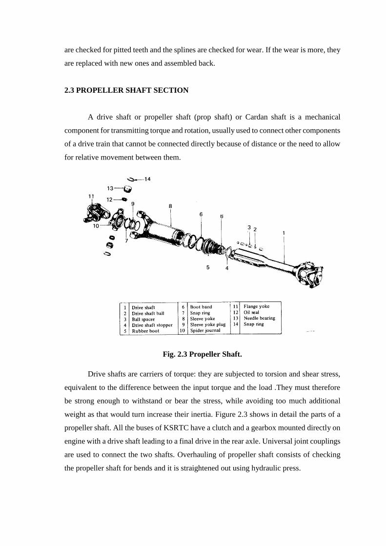
Fig. 2.3 Propeller Shaft.
Drive shafts are carriers of torque: they are subjected to torsion and shear stress,
equivalent to the difference between the input torque and the load .They must therefore
be strong enough to withstand or bear the stress, while avoiding too much additional
weight as that would turn increase their inertia. Figure 2.3 shows in detail the parts of a
propeller shaft. All the buses of KSRTC have a clutch and a gearbox mounted directly on
engine with a drive shaft leading to a final drive in the rear axle. Universal joint couplings
are used to connect the two shafts. Overhauling of propeller shaft consists of checking
the propeller shaft for bends and it is straightened out using hydraulic press.
2.4 SMALL UNIT SECTION
Small unit section consists of reassembling of clutch, air brake compressor, DD
unit, air drier.
2.4.1 Air Brake Unit
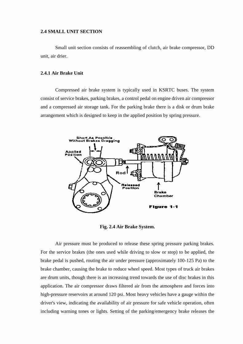
Compressed air brake system is typically used in KSRTC buses. The system
consist of service brakes, parking brakes, a control pedal on engine driven air compressor
and a compressed air storage tank. For the parking brake there is a disk or drum brake
arrangement which is designed to keep in the applied position by spring pressure.
Fig. 2.4 Air Brake System.
Air pressure must be produced to release these spring pressure parking brakes.
For the service brakes (the ones used while driving to slow or stop) to be applied, the
brake pedal is pushed, routing the air under pressure (approximately 100-125 Pa) to the
brake chamber, causing the brake to reduce wheel speed. Most types of truck air brakes
are drum units, though there is an increasing trend towards the use of disc brakes in this
application. The air compressor draws filtered air from the atmosphere and forces into
high-pressure reservoirs at around 120 psi. Most heavy vehicles have a gauge within the
driver's view, indicating the availability of air pressure for safe vehicle operation, often
including warning tones or lights. Setting of the parking/emergency brake releases the
pressurized air pressure in the lines between the compressed air storage tank and the
brakes. Thus actuating the (spring brake) parking brake hardware. An air pressure failure
at any point would apply full spring brake pressure immediately.
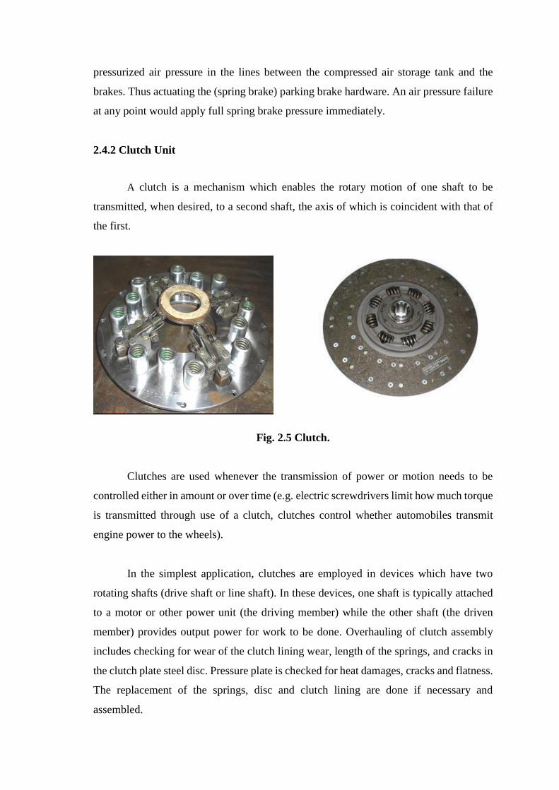
2.4.2 Clutch Unit
A clutch is a mechanism which enables the rotary motion of one shaft to be
transmitted, when desired, to a second shaft, the axis of which is coincident with that of
the first.
Fig. 2.5 Clutch.
Clutches are used whenever the transmission of power or motion needs to be
controlled either in amount or over time (e.g. electric screwdrivers limit how much torque
is transmitted through use of a clutch, clutches control whether automobiles transmit
engine power to the wheels).
In the simplest application, clutches are employed in devices which have two
rotating shafts (drive shaft or line shaft). In these devices, one shaft is typically attached
to a motor or other power unit (the driving member) while the other shaft (the driven
member) provides output power for work to be done. Overhauling of clutch assembly
includes checking for wear of the clutch lining wear, length of the springs, and cracks in
the clutch plate steel disc. Pressure plate is checked for heat damages, cracks and flatness.
The replacement of the springs, disc and clutch lining are done if necessary and
assembled.
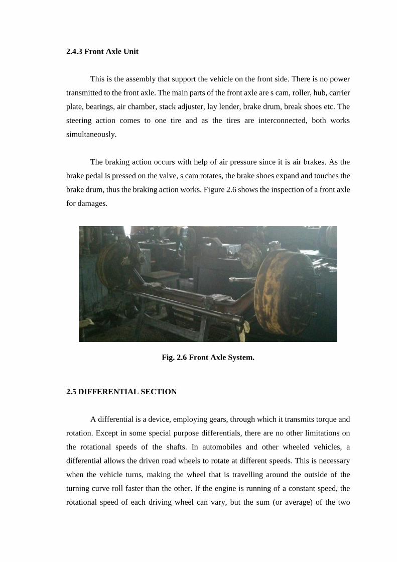
2.4.3 Front Axle Unit
This is the assembly that support the vehicle on the front side. There is no power
transmitted to the front axle. The main parts of the front axle are s cam, roller, hub, carrier
plate, bearings, air chamber, stack adjuster, lay lender, brake drum, break shoes etc. The
steering action comes to one tire and as the tires are interconnected, both works
simultaneously.
The braking action occurs with help of air pressure since it is air brakes. As the
brake pedal is pressed on the valve, s cam rotates, the brake shoes expand and touches the
brake drum, thus the braking action works. Figure 2.6 shows the inspection of a front axle
for damages.
Fig. 2.6 Front Axle System.
2.5 DIFFERENTIAL SECTION
A differential is a device, employing gears, through which it transmits torque and
rotation. Except in some special purpose differentials, there are no other limitations on
the rotational speeds of the shafts. In automobiles and other wheeled vehicles, a
differential allows the driven road wheels to rotate at different speeds. This is necessary
when the vehicle turns, making the wheel that is travelling around the outside of the
turning curve roll faster than the other. If the engine is running of a constant speed, the
rotational speed of each driving wheel can vary, but the sum (or average) of the two
wheels speeds cannot change. An increase in the speed of one wheel must be balanced by
an equal decrease in the speed of the other.
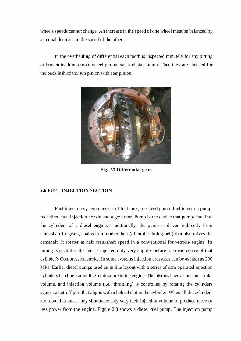
In the overhauling of differential each tooth is inspected minutely for any pitting
or broken teeth on crown wheel pinion, sun and star pinion. Then they are checked for
the back lash of the sun pinion with star pinion.
Fig. 2.7 Differential gear.
2.6 FUEL INJECTION SECTION
Fuel injection system consists of fuel tank, fuel feed pump, fuel injection pump,
fuel filter, fuel injection nozzle and a governor. Pump is the device that pumps fuel into
the cylinders of a diesel engine. Traditionally, the pump is driven indirectly from
crankshaft by gears, chains or a toothed belt (often the timing belt) that also drives the
camshaft. It rotates at half crankshaft speed in a conventional four-stroke engine. Its
timing is such that the fuel is injected only very slightly before top dead centre of that
cylinder's Compression stroke. In some systems injection pressures can be as high as 200
MPa. Earlier diesel pumps used an in line layout with a series of cam operated injection
cylinders in a line, rather like a miniature inline engine. The pistons have a constant stroke
volume, and injection volume (i.e., throttling) is controlled by rotating the cylinders
against a cut-off port that aligns with a helical slot in the cylinder. When all the cylinders
are rotated at once, they simultaneously vary their injection volume to produce more or
less power from the engine. Figure 2.8 shows a diesel fuel pump. The injection pump
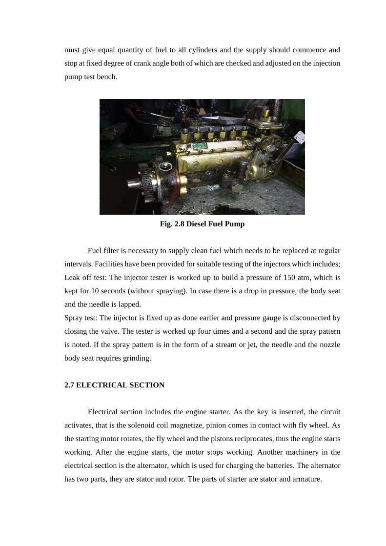
must give equal quantity of fuel to all cylinders and the supply should commence and
stop at fixed degree of crank angle both of which are checked and adjusted on the injection
pump test bench.
Fig. 2.8 Diesel Fuel Pump
Fuel filter is necessary to supply clean fuel which needs to be replaced at regular
intervals. Facilities have been provided for suitable testing of the injectors which includes;
Leak off test: The injector tester is worked up to build a pressure of 150 atm, which is
kept for 10 seconds (without spraying). In case there is a drop in pressure, the body seat
and the needle is lapped.
Spray test: The injector is fixed up as done earlier and pressure gauge is disconnected by
closing the valve. The tester is worked up four times and a second and the spray pattern
is noted. If the spray pattern is in the form of a stream or jet, the needle and the nozzle
body seat requires grinding.
2.7 ELECTRICAL SECTION
Electrical section includes the engine starter. As the key is inserted, the circuit
activates, that is the solenoid coil magnetize, pinion comes in contact with fly wheel. As
the starting motor rotates, the fly wheel and the pistons reciprocates, thus the engine starts
working. After the engine starts, the motor stops working. Another machinery in the
electrical section is the alternator, which is used for charging the batteries. The alternator
has two parts, they are stator and rotor. The parts of starter are stator and armature.
2.8 STEERING SECTION
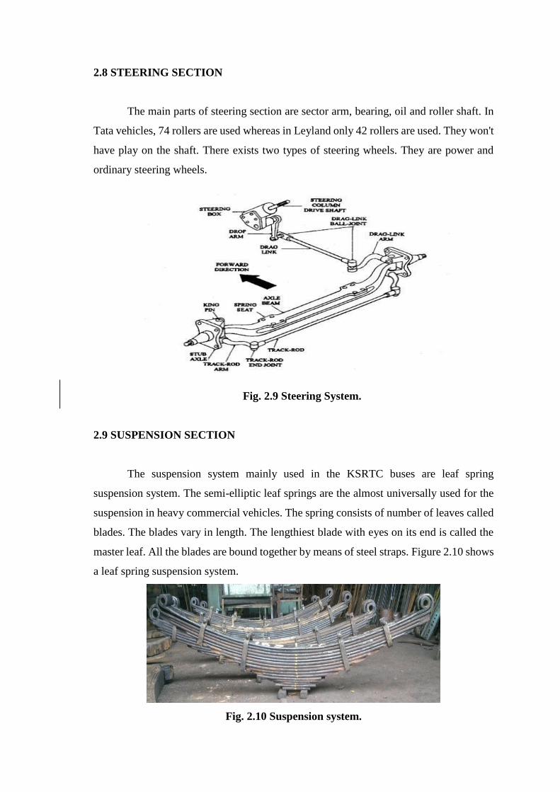
The main parts of steering section are sector arm, bearing, oil and roller shaft. In
Tata vehicles, 74 rollers are used whereas in Leyland only 42 rollers are used. They won't
have play on the shaft. There exists two types of steering wheels. They are power and
ordinary steering wheels.
Fig. 2.9 Steering System.
2.9 SUSPENSION SECTION
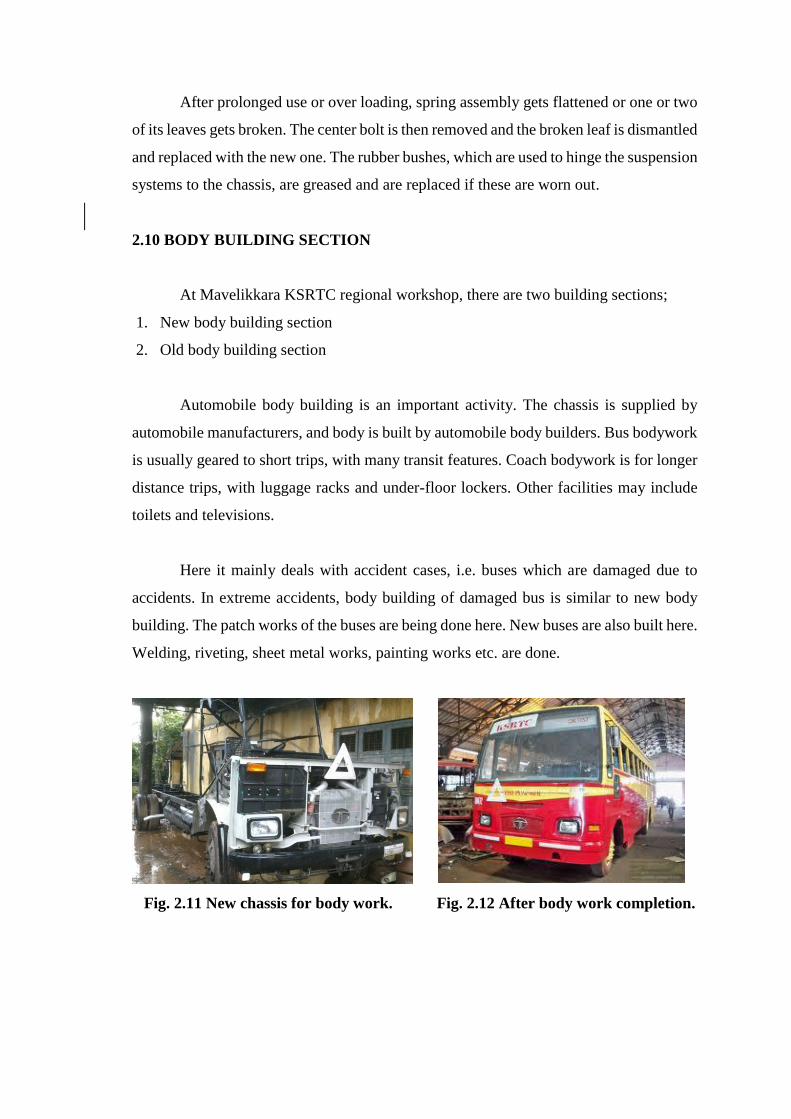
The suspension system mainly used in the KSRTC buses are leaf spring
suspension system. The semi-elliptic leaf springs are the almost universally used for the
suspension in heavy commercial vehicles. The spring consists of number of leaves called
blades. The blades vary in length. The lengthiest blade with eyes on its end is called the
master leaf. All the blades are bound together by means of steel straps. Figure 2.10 shows
a leaf spring suspension system.
Fig. 2.10 Suspension system.
After prolonged use or over loading, spring assembly gets flattened or one or two
of its leaves gets broken. The center bolt is then removed and the broken leaf is dismantled
and replaced with the new one. The rubber bushes, which are used to hinge the suspension
systems to the chassis, are greased and are replaced if these are worn out.
2.10 BODY BUILDING SECTION
At Mavelikkara KSRTC regional workshop, there are two building sections;
1. New body building section
2. Old body building section
Automobile body building is an important activity. The chassis is supplied by
automobile manufacturers, and body is built by automobile body builders. Bus bodywork
is usually geared to short trips, with many transit features. Coach bodywork is for longer
distance trips, with luggage racks and under-floor lockers. Other facilities may include
toilets and televisions.
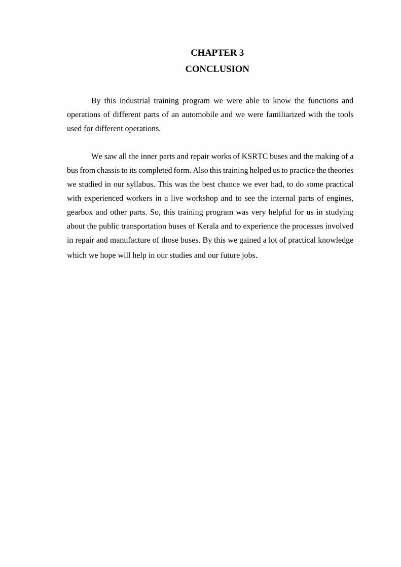
Here it mainly deals with accident cases, i.e. buses which are damaged due to
accidents. In extreme accidents, body building of damaged bus is similar to new body
building. The patch works of the buses are being done here. New buses are also built here.
Welding, riveting, sheet metal works, painting works etc. are done.
Fig. 2.11 New chassis for body work. Fig. 2.12 After body work completion.
CHAPTER 3
CONCLUSION
By this industrial training program we were able to know the functions and
operations of different parts of an automobile and we were familiarized with the tools
used for different operations.
We saw all the inner parts and repair works of KSRTC buses and the making of a
bus from chassis to its completed form. Also this training helped us to practice the theories
we studied in our syllabus. This was the best chance we ever had, to do some practical
with experienced workers in a live workshop and to see the internal parts of engines,
gearbox and other parts. So, this training program was very helpful for us in studying
about the public transportation buses of Kerala and to experience the processes involved
in repair and manufacture of those buses. By this we gained a lot of practical knowledge
which we hope will help in our studies and our future jobs.