Embed Size (px)
Citation preview

IndustrialIT for Utility Communications
CommunicateIT Power Line Carrier ETL500
2
Features
■ Software programmable Power Line Carrier(PLC) unit for the transmission of speech,data and protection signals
■ Latest signal processor technology permitstailor-made solutions for each specificapplication, with optimal operating behav-iour, even under the most adverse lineconditions
■ Optional fitting with digital multiplexerAMX500 for operation with data rates upto 64 kbps
■ Adaptive adjustment of the data rate ac-cording to the prevailing line characteristics
■ Integrated, software programmable pro-tection signalling equipment NSD550 formaximum performance
■ Integrated NSK5 data modem for low-speed data channels for SCADA applications
■ Three transmission power classes (5 watt, 40 watt,80 watt) available, utilizable according to line conditions
■ Programmable over the carrier frequency range 24 to 500 kHz
■ Operation with 1 or 2 transmission channels■ Direct Digital frequency Synthesis (DDS) provides
maximum stability of the frequency conversion ■ Standard interfaces for speech transmission and
telecontrol applications■ Modular compact design for minimum hardware
expenditure and maximum reliability■ Windows based Man-Machine Interface MMI500■ Embedded Operations Channel (EOC) for
remote monitoring and remote configuration ofthe equipment
■ Remote access via Internet and dial-up modem■ Meets or exceeds IEC 60495 and IEC 60834-1
requirements■ Complies with safety and electromagnetic
capability (EMC) requirements of the EuropeanCommunity (EC)
Applications
The fully digital ETL500 Power Line Carrier set is amultipurpose equipment designed for the transmis-sion of speech, data and protection signals overpower lines or cables. The equipment can be usedon power lines of any voltage level or length.Moreover, with the considerably enhanced transmis-sion capacity provided by the digital add-on facilityAMX500, several new applications can be identified.
■ The frequency congestion problem is considerablyrelieved, as several times more information can bepacked into the same carrier frequency band, therefore fewer RF carrier channels are needed.
■ With 64 kbps transmission rate, a cost-efficientinterconnection between digital wideband net-works can be established.
■ High-capacity PLC link is also best suited to serveas a back-up path for vital information conveyedthrough fibre-optic or microwave links.

3
Solution to frequency congestionBecause of the limitation of the availablePLC frequency spectrum, the extension of existing networks often becomes very difficult. An ETL500 equipped with theAMX500 may replace 2 to 4 existing ana-logue PLC links and therefore provides asolution to bottlenecks in the existingPLC network. For a given number of services, the number of PLC channels needed can be reduced significantly andtherefore frequency allocation becomeseasier. The example beside illustrates howthe frequency allocation scheme can be
Station
Transmission lines
A
B
C
D
E
4 kHz steps
Analog PLC
Tx Rx
Digital PLC
replaced
LT LT
ETL500
MS FAX
DC M
PR PC PAX
C
ETL500
FAXPR PC
C
RTU
M
C DC FAX LT M
= Coupling Device = Dispatcher's Console = Facsimile equipment = Line trap = Modem
MS PAX PR PC RTU
= Master Station = Privat Automatic Exchange = Protection Relay = Personal Computer = Remote Terminal Unit
M
ETL500 Power Line Carrier equipment is suitable for a wide range of applications
Digital PLC relieves the problem of frequency congestion

Wideband system PDH/SDH2 Mbps to 622 Mbps
PLC Narrowband Back-up≤ 64 kbps
X.21 X.21
X.21
AMX 500
X.21
AMX 500NSD 550 NSD 550
made less dense if analogue carrier sets are replacedby their digital counterparts. This provides frequencyspace for the new carrier channels to be allocated.
Back-up of wideband communication linksWith the standard serial data interface according toITU-T X.21 provided by the AMX500, the system isprepared for being connected to a PDH (Plesiochro-nous Digital Hierarchy) multiplexer. This opens up avariety of options for accessing to a digital widebandnetwork.
At the outskirts of a power system communicationsnetwork there is usually low-density traffic whichdoes not justify the investment for a high-capacityfibre installation. With digital PLC equipment, a low-cost tributary link to the wideband backbone systemmay be installed as an alternative.
Digital PLC is also a favourable alternative whenthere is a need to establish stand-by routes for criti-cal services in high-capacity networks, i.e. fibre-opticlinks and microwave links.
Customer benefits
Robust designThe ETL500 concept is based on ABB’s long experi-ence in the field of power line carrier equipment.The electrical and the mechanical design make use ofthe most advanced technologies. Design principlesproven in the area of power system communicationenable the ETL500 equipment to withstand harshenvironmental conditions.
Whilst using latest processor technology, the numberof modules could be greatly reduced. The shrinkingof the hardware to a bare minimum ensures maxi-mum reliability. Furthermore, the reduced numberof different spare parts results in considerable costsavings.
The ETL505 with 5 watt power outputconsists of one 19” subrack, 6 units high,comprising the complete set of functionalmodules. Application of this type ofequipment is adequate for medium voltagepower lines of short to moderate distance.For the ETL540 / ETL580 versions, one re-spectively two more subracks of 3 unitshigh, comprising the power modules, haveto be added. The 40 watt or 80 watt poweroutput is needed for applications on lon-ger high-voltage power lines. The front picture displays the tier blockcomplement of the ETL540 together withAMX500.
Enhanced transmission capacity■ The use of a new type, adaptive, digital transmis-
sion procedure permits maximum utilization ofthe transmission capacity of a PLC channel. Thehigh-efficiency transmission is achieved by thefunctional unit AMX500, comprising signal con-verter, multiplexer and additional modules for thespeech compression.
4
Back-up systems for backbone channels

Investment protection■ Any PLC equipment can be retrofitted with
the AMX500 to increase capacity. This enablesexisting communication infrastructure to be usedmore efficiently without the need for high rein-vestment. For example, one AMX500 is often sufficient for the additional transfer of a fewspeech and data services; the requirement forcostly wideband equipment is dispensed with.
■ The concept allows for a seamless transition froman ETL500 equipment working in standard mode to a PLC set operated in high-capacitymode by adding the AMX500 unit housed in itsown subrack.
■ Retrofitting and upgrading an ETL500 equipmentinto one working in high-capacity mode is pos-sible any time on site.
■ Frequency allocation in an existing network willremain unaffected, i.e. there is no need to changeline traps and coupling filters.
Operational flexibility, modes of operation Unique features, such as single-step digital frequencyconversion, automatic channel equalization, con-figurable AF options, event recorder, built-in testfacilities, to name just a few, add to the operationalflexibility.
The Direct Digital Synthesis method, which is usedto generate the RF signal, results in excellent qualityand stability of the AF to RF and RF to AF conver-sions. The carrier frequency parameters detailedbelow are easily configured by means of the user-friendly MMI500.
■ Carrier frequency: Can be set in steps of 500 Hzin the frequency range from 24 to 500 kHz
■ Number of channels: 1 or 2■ Channel-bandwidth: 4 or 8 kHz■ Position of the individual sidebands: Can be
configured individually to be in the upright orinverted position
The ETL500 design is unique as it combines robustness and transparency of analogue equipmentwith the advantage of increased transmission capa-city provided by digital transmission equipment.This feature makes the equipment compatible withexisting analogue PLC systems and results in out-standing flexibility with regard to the applications.
The system may be used in various modes of opera-tion depending on the requirements, type of ser-vices, line conditions, etc. Three examples illustratepossible ways of using a given frequency band anddemonstrate the versatility of the ETL500 system.
Example 1:When using ETL500 single channel equipment thecapacity can considerably be enhanced by adding the AMX500 unit. A possible configuration is illustrated below. This arrangement permits a datachannel with a transmission rate of 4800 bps to be superimposed above the speech channel, withinwhich the tones for protection signalling are allo-cated.
ETL540 + AMX500 / 4 kHz
Single channel equipment with superimposed fast data channel
■ 1 speech channel band limited
■ Teleprotection function with NSD550
■ 1 data channel synchronous 4800 bps
5
Speech Pilot
4 kHz
DataAMX
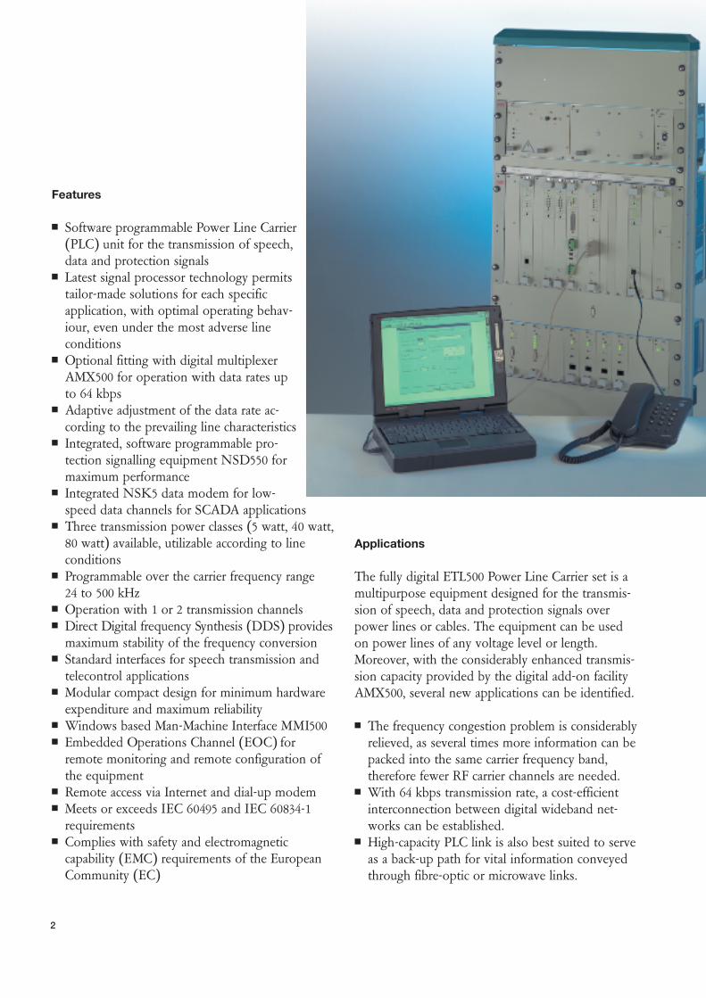
Example 2:The illustration above depicts an ETL500 doublechannel equipment, occupying 8 kHz bandwidth.With this configuration one channel may be ex-ploited for operational speech combined with tele-protection and low-speed data for SCADA applica-tion, whilst the other channel may convey high-speed data and several compressed speech channels.
Example 3:The illustration above on the right side shows anETL500 single channel equipment requiring 8 kHzband, but configured to work in high-speed modeusing the entire bandwidth. With this configurationa transmission rate up to 64 kHz may be obtainedunder favourable line conditions. A possible sub-division of the available capacity among differentservices may be as follows:
2 speech channels1 data channels 19.2 kbps synchronous3 data channels 2.4 kbps asynchronous.
Optimum performance of the teleprotection serviceis ensured by the NSD550 which operates entirelyindependent of the AMX500 unit.
Easy commissioning, testing, supervision, and maintenanceAll operating states are monitored, recorded, and evaluated by the CPU module P4LQ, which alsotakes care of the frequency up-and-down conversion.The ETL500 comes with the software MMI500,which is a Windows® based program running onany standard PC.
When a serial port of the PC is connected to theSUB-D connector on the frontplate of the moduleP4LQ, the MMI500 implements a man-machine-interface (MMI) for the ETL500, supporting com-missioning, testing, troubleshooting, supervision,and maintenance.
In addition to the alarms displayed by the MMI500,LEDs on the front panel light up when an alarm isactivated. Appropriate actions on the module arestarted and there are three switchover relay contactsavailable for issuing an alarm. Eight more relaycontacts can be provided with the optional alarmrelay module R1BC. Two alarm criteria which can beassociated with these contacts may be specified and
6
Speech Pilot Pilot
4 kHz 4 kHz
Data AMXData NSK Pilot
8 kHz
Data AMX
ETL540 + AMX500 / 8 kHz
Double channel equipment configured for hybrid mode of operation
■ Channel 1:
1 speech channel band limited
3 low-speed FSK channels 200 baud for SCADA application
Teleprotection function with NSD550
■ Channel 2:
High-speed mode of operation, aggregate data rate ≤ 28.8 kbps carrying:
1 speech channel
1 data channel synchronous 14.4 kbps
2 data channels asynchronous 2.4 kbps
ETL540 + AMX500 / 8 kHz
Single channel equipment configured for high-speed operation occupying
8 kHz bandwidth
Aggregate data rate ≤ 64 kbps carrying e.g.:
■ 2 speech channels
■ 1 data channels synchronous 19.2 kbps
■ 3 data channels asynchronous 2.4 kbps
■ Teleprotection function (with NSD550)
entered by means of the MMI500. Non-critical alarmsituations are signalled as ‘‘deferred” alarms.For network extensions, Tx and Rx filters can besimply re-tuned on site with the aid of two tuningadapters and a level meter.
Man-machine interface MMI500The MMI500, a 32-bit Windows® program runningon any standard PC, offers:■ “Off line” configuration of an ETL500 terminal
with the facility for saving the settings in a file forlater use, e.g. download it when an ETL500equipment has to be configured accordingly.
■ Configuration and supervision of both the localand the remote terminal of an ETL500 link fromeither side of the link.
■ Dialog windows to configure all the settings ofthe ETL500 equipment, e.g. carrier frequency characteristics, alarm parameters, AF interface functions, NSD550 parameters, equipment iden-tification, etc.
■ View windows displaying detailed status andalarm information of the ETL500 intext or graphic form, which can becopied into documents, printed outor saved to a file.
■ Measuring facilities which can access anumber of AF test points internal tothe ETL500 and display the signals in graphic form in the frequencydomain format.
■ Automatic channel equalization ofamplitude and group-delay responseof the complete AF band in bothtransmission directions from one sideof the link. Graphic display of theequalized and of the non-equalizedfrequency response is provided. Theinformation can be printed out orsaved.
■ Automatic polling and logging ofalarms to a file in the PC.
■ Assistance for tuning and testing of the local ETL500 terminal. All signals needed for tuningand testing the RF filters and AF options aregenerated.
■ Help utility with explanations for all actions supported by the MMI.
■ Event recorder for 1000 teleprotection events and1000 alarm events with a time resolution of 1 msif synchronized to a GPS clock.
■ When the ETL500 equipment is integrated in anetwork management system, each equipment canbe accessed via a unique device number.
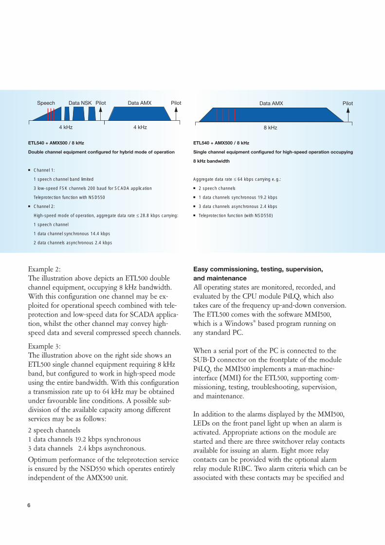
The architecture of the digital PLC equipmentETL500
The schematic block diagram below shows an over-view of the simple and extremely practical systemarchitecture. The construction of a full PLC multi-purpose equipment requires only a few functionalunits which communicate via the internal bus. The basic unit comprises solely the interface for the
7
NSK5
NSD 550processing
AF / RFConversion
LineInterface
Supervision
P4LQ
Alarms
AMX500
RF
Sys
tem
Bus
G4AI
O4LE
Data anisochronous
E & MSignalling
Speech+ inband signalling
Teleoperation(Modem, FSK)
Teleprotection
Speech, E & M Signalling, Inbandsignalling, FAXData, synch., asynch. ≤ 64 kbps,RS-422, X.21
Block diagramm ETL500 + AMX500

speech and telecontrol signals O4LE, the separatecommand interface for the protection signal trans-mission G4AI and the central processor unit P4LQwhich deals with the various signal processing andmonitoring functions. Where required, the modemNSK5 is available for transferring low-speed data for SCADA applications. Also required is the lineinterface via which the signal exchange takes placefrom and to the coupling unit.
The degree of utilization of the channel capacity canbe considerably increased by using the digital multi-plexer / signal converter AMX500.
An essential feature is the fact that mission criticalservices can be conducted via modules operatedseparately from the AMX500 unit. The rigorousdemands of these critical services with respect totransmission time and interference can be satisfiedexcellently by this separation.
The configuration and monitoring of the systemtakes place by PC via the diagnostic interface.
Central processor unit P4LQThe following central functions are executed on thefunctional unit P4LQ:■ Digital SSB (Single Side Band) modulation in the
DDS procedure■ Central monitoring of the hardware and software
functions■ Generation and evaluation of the pilot signal for a
wide range of functions■ Frequency synchronization■ Signal quality monitoring■ Automatic frequency response measurement and
channel equalizing■ Serial interface for PC connection for the equip-
ment configuration and monitoring
RF line interfaceThe line interface comprises all the functional unitsnecessary for the transmission and receive side signalcoupling to the high-voltage line. These are thepower amplifier, RF hybrid, transmit and receive fil-ters.
ETL500 equipment is available in 3 power classes:■ ETL505 with 5 watt output power
Application of this type of equipment is adequatefor medium voltage power lines of short tomoderate distance.
■ ETL540 / ETL580 with 40 watt and 80 watt output power 40 watt or 80 watt output power is needed forapplications on long high-voltage power lines.
AF interface O4LEThe universal interface module O4LE provides anaudio frequency interface for the following applica-tions:
Telephony■ Point-to-point hot line■ Remote subscriber■ 4-wire PABX interface with E&M■ 2/4-wire PABX interface with E&M and hybrid
control■ Service telephone
Teleoperation■ Transmission of audio frequency data signals
from modems■ Programmable transit filter
Connection of external teleprotection equipment, such as NSD70C■ External teleprotection equipment ■ Signal boosting control
The unit is fully programmable via PC / MMI500.
8
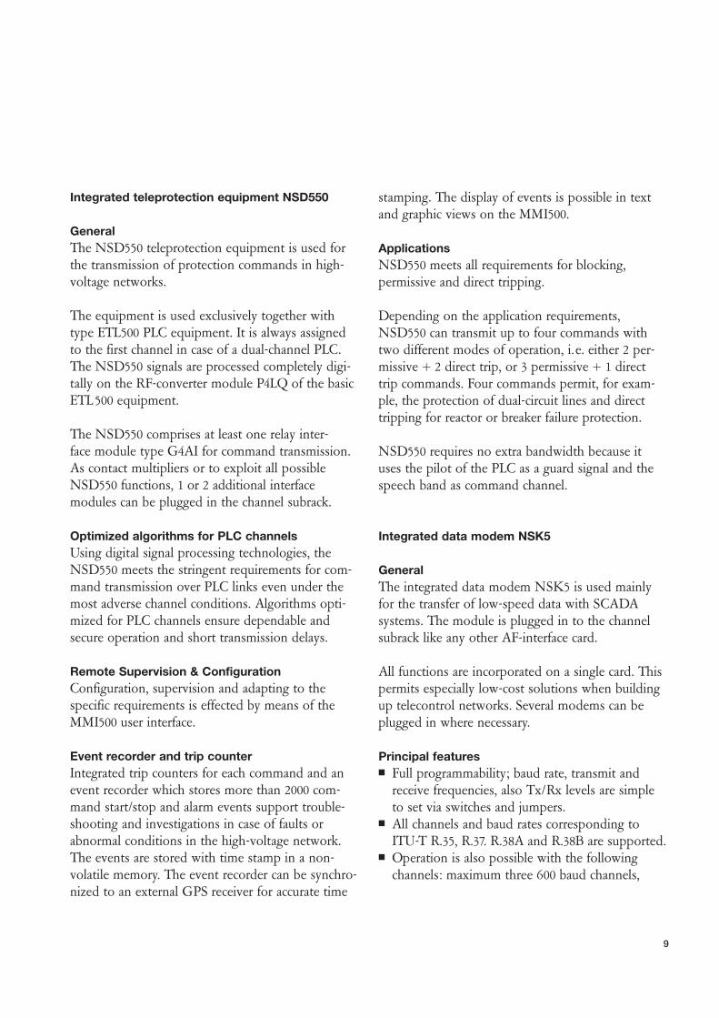
Integrated teleprotection equipment NSD550
GeneralThe NSD550 teleprotection equipment is used forthe transmission of protection commands in high-voltage networks.
The equipment is used exclusively together withtype ETL500 PLC equipment. It is always assignedto the first channel in case of a dual-channel PLC.The NSD550 signals are processed completely digi-tally on the RF-converter module P4LQ of the basicETL500 equipment.
The NSD550 comprises at least one relay inter-face module type G4AI for command transmission.As contact multipliers or to exploit all possible NSD550 functions, 1 or 2 additional interface modules can be plugged in the channel subrack.
Optimized algorithms for PLC channelsUsing digital signal processing technologies, theNSD550 meets the stringent requirements for com-mand transmission over PLC links even under themost adverse channel conditions. Algorithms opti-mized for PLC channels ensure dependable andsecure operation and short transmission delays.
Remote Supervision & ConfigurationConfiguration, supervision and adapting to the specific requirements is effected by means of the MMI500 user interface.
Event recorder and trip counterIntegrated trip counters for each command and anevent recorder which stores more than 2000 com-mand start/stop and alarm events support trouble-shooting and investigations in case of faults or abnormal conditions in the high-voltage network. The events are stored with time stamp in a non-volatile memory. The event recorder can be synchro-nized to an external GPS receiver for accurate time
stamping. The display of events is possible in textand graphic views on the MMI500.
ApplicationsNSD550 meets all requirements for blocking, permissive and direct tripping.
Depending on the application requirements, NSD550 can transmit up to four commands withtwo different modes of operation, i.e. either 2 per-missive + 2 direct trip, or 3 permissive + 1 directtrip commands. Four commands permit, for exam-ple, the protection of dual-circuit lines and directtripping for reactor or breaker failure protection.
NSD550 requires no extra bandwidth because ituses the pilot of the PLC as a guard signal and thespeech band as command channel.
Integrated data modem NSK5
GeneralThe integrated data modem NSK5 is used mainlyfor the transfer of low-speed data with SCADAsystems. The module is plugged in to the channelsubrack like any other AF-interface card.
All functions are incorporated on a single card. Thispermits especially low-cost solutions when buildingup telecontrol networks. Several modems can beplugged in where necessary.
Principal features■ Full programmability; baud rate, transmit and
receive frequencies, also Tx/Rx levels are simpleto set via switches and jumpers.
■ All channels and baud rates corresponding toITU-T R.35, R.37. R.38A and R.38B are supported.
■ Operation is also possible with the followingchannels: maximum three 600 baud channels,
9
one 1200 baud channel for frequencies above 2000 Hz (speech) or in combination with otherlow-speed data channels; one 1200 baud channel corresponding to ITU-T V.23 or one 2400 baudchannel.
■ Distortion of the characteristic is minimized by ahelp module for synchronization, a data regenera-tor and equalizer.
■ A serial data interface corresponding to ITU-TV.24, V.28, and V.10 is available with front accessfor test purposes.
■ The modem is electrically isolated from the ETL500 modules.
■ A local loop test is possible. It can be initializedeither via the test switch on the front panel or thecorresponding interface line.
■ The bit error rate can be tested over the total linelength.
Multiplexer/converter unit AMX500
In an endeavour to enhance the transmission capacity of the available PLC frequency spectrum, a great deal of effort has been spent investigatingmore efficient signalling methods for power line carrier application.
PLC equipment ETL500 with theoptional add-on unit AMX500using techniques such as low bit-rate speech coding combinedwith time domain multiplexingand digital modulation can pro-vide several times the transmis-sion capacity per link under good line conditions, comparedto traditional PLC circuits.
Principal features■ Transmission speed is automatically adjusted to
the prevailing channel conditions in order toensure maximum system availability, e.g. if datatransmission at a set speed suffers from insuffi-cient quality because of poor line conditions, fall-back to an appropriate lower transmission ratewill restore the quality of service to the levelrequired.
■ Robust, bandwidth-efficient digital modulation■ Adaptive adjustment to the channel characteristics■ Adjustable bandwidth
The bandwidth of the transmission system can be individually set between 1000 and 7300 Hz for each application. 8 different bandwidths areavailable.
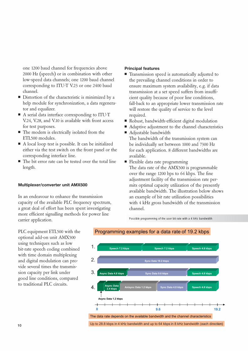
■ Flexible data rate programmingThe data rate of the AMX500 is programmableover the range 1200 bps to 64 kbps. The fineadjustment facility of the transmission rate per-mits optimal capacity utilization of the presentlyavailable bandwidth. The illustration below showsan example of bit rate utilization possibilities with 4 kHz gross bandwidth of the transmissionchannel.
10
0 9.6 19.2
Sync Data 19.2 kbps
Speech 7.2 kbps Speech 7.2 kbps Speech 4.8 kbps
Async Data 4.8 kbps Sync Data 9.6 kbps Speech 4.8 kbps
1.
2.
3.
4. Async Data2.4 kbps Anisync Data 1.2 kbps Sync Data 4.8 kbps Speech 4.8 kbps
Async Data 1.2 kbps
Programming examples for a data rate of 19.2 kbps
Up to 28.8 kbps in 4 kHz bandwidth and up to 64 kbps in 8 kHz bandwidth (each direction)
The data rate depends on the available bandwidth and the channel characteristics
Possible programming of the user bit rate with a 4 kHz bandwidth

11
Planning information
The following diagram is for supporting the planning of PLC links with digital transmission, i.e. when using the AMX500. Represented is therelation between bit rate and necessary signal-to-noise ratio (SNR) for a given maximum bit errorrate and bandwidth. The bit rates shown are for thenet bandwidths 1.4 / 1.7 / 2.1 / 3.3 and 7.0 kHz andfor a bit error rate (BER) of 10 -6.
The curves are based on a large number of field andsimulation tests.
Example: A noise ratio of 37 dB is necessary with a 3.3 kHz bandwidth for a transmission rate of 28.8 kHz.
*
*
*
BW 7.0 kHz
BW 3.3 kHz
BW 2.1 kHz
BW 1.7 kHz
BW 1.4 kHz
4030 3520 25 SNR (dB)
Bit rate (kbps)
10 15
70.0
60.0
50.0
40.0
30.0
20.0
10.0
0.0
Bandwidth:
Bit rate / SNR characteristic (noise measured in 4 kHz bandwith)

12
TECHNICAL DATA
PLC part
All modules of the ETL500 comply with or exceed the requirementsaccording to IEC Publication 60495, second edition, Sept. 1993, withreference to single sideband PLC equipment. ETL500 complies withEuropean EMC Directive 89/336/EEC and the Low-Voltage Directive73/23/EEC.
System data
System dataOperating mode Single sideband mode with
suppressed carrierCarrier frequency range Total range 24 to 500 kHz
40 to 500 kHz programmable
AF bandwidth 300 to 4000 Hz / 300 to 8000 Hz
Output rated impedance 75 or 125 ohm unbalanced, optional150 ohm balanced
Service PC interface RS-232 / 9600 bps
Alarm outputs potential-free changeover contacts for – system alarm / cabinet alarm– hardware alarm– link alarm
Type ETL505 ETL540 ETL540Number of channels 1 1 2Nominal bandwidth 4 kHz 4 kHz 8 kHzMax. line attenuation 51 dB 60 dB 54 dB
Due to line noise,the line attenuationshould not exceed the following values 25 to 30 dB 35 to 40 dB 30 to35 dB
ff Type ETL580 ETL580Number of channels 1 2Nominal bandwidth 4 KHz 8 KHzMax. line attenuation 63 dB 57 dB
Due to line noise,the line attenuationshould not exceed the following values 38 to 43 dB 33 to 38 dB
Ambient conditionsNormal operation complies with Climatic conditions IEC 60721-3-3, class 3K5Temperature range –5 to +45 0CRelative humidity ≤ 95%
Reliable operation up to +55 0CMechanical conditions complies with
IEC 60721-3-3, class 3M1
Electromagnetic compati-bility and insulation tests Complies with the EMC requirements for:Emission EN 50081-2 (EN 55022 class A)Immunity EN 50082-2
Electrical safetyComplies with the safety requirements according to IEC 60950 / EN 60950
Transmitter data
Transmitter dataType ETL505 ETL540 ETL580HF output power 5 W 40 W 80 WPeak Envelope Power (PEP) (+37 dBm) (+46 dBm) (+49 dBm)
Pilot channel:Available frequencies 2160 ... 3840 Hz adjustable with MMI
in 60 Hz steps Nominal frequency 3840 Hz
Receiver data
RF sensitivity referred to the test tone level at the RF input: –30 dBm
Automatic level regulation: AF output level constant within 1 dB at +14/ –26 dB fluctuations of the RF receive level
Alarm outputs
P4LQ alarm outputs R1BC alarm outputs
With hardware, 8 relays, jumper programmablelink and cabinet alarm for cabinet alarm or softwareNormally closed (NC) or configurable alarms 1 or 2 with normally open (NO) contacts MMI500
Normally closed (NC) or normallyopen (NO) contacts
13
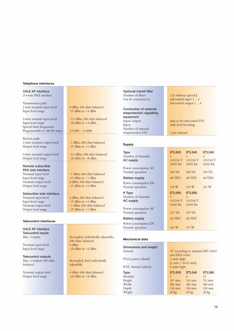
Telephone interfaces
O4LE AF interface 2/4-wire PAX interface
Transmission path:2-wire nominal input level 0 dBm, 600 ohm balancedInput level range –17 dBm to +4 dBm
4-wire nominal input level –3.5 dBm, 600 ohm balancedInput level range –20 dBm to +4 dBmSpeech limit frequenciesProgrammable in 200 Hz steps: 2.0 kHz - 3.4 kHz
Receive path:2-wire nominal output level –7 dBm, 600 ohm balancedOutput level range –17 dBm to +1 dBm
4-wire nominal output level –3.5 dBm, 600 ohm balancedOutput level range –20 dBm to +8 dBm
Remote subscriberPAX side interfaceNominal input level –7 dBm, 600 ohm balancedInput level range –17 dBm to +1 dBm Nominal output level 0 dBm, 600 ohm balancedOutput level range –17 dBm to +4 dBm
Subscriber side interfaceNominal input level 0 dBm, 600 ohm balanced Input level range –17 dBm to +4 dBm Nominal output level –7 dBm, 600 ohm balancedOutput level range –17 dBm to +1 dBm
Telecontrol interfaces
O4LE AF interface Telecontrol inputsMax. 4 inputs decoupled, individually adjustable,
600 ohm, balancedNominal input level 0 dBmInput level range –20 dBm to +4 dBm
Telecontrol outputsMax. 4 outputs 600 ohm decoupled, level individually balanced adjustable
Nominal output level 0 dBm, 600 ohm balancedOutput level range –20 dBm to +8 dBm
Optional transit filterNumber of filters 2 (4 without speech)Can be connected to telecontrol input 1 ... 4
telecontrol output 1 ... 4
Connection of external teleprotection signalling equipmentInput /output data as for telecontrol I/O Input with level boostingNumber of externalteleprotection I/O 1 per channel
Supply
Type ETL505 ETL540 ETL540Number of channels 1 1 2AC supply 115/230 V 115/230 V 115/230 V
50/60 Hz 50/60 Hz 50/60 HzPower consumption ACNormal operation 160 VA 180 VA 190 VA
Battery supply 48 VDC 48 VDC 48 VDC
Power consumption DCNormal operation 110 W 125 W 135 W
ff Type ETL580 ETL580Number of channels 1 2AC supply 115/230 V 115/230 V
50/60 Hz 50/60 HzPower consumption ACNormal operation 235 VA 245 VA
Battery supply 48 VDC 48 VDC
Power consumption DCNormal operation 165 W 175 W
Mechanical data
Dimensions and weightSubrack 19” according to standard IEC 60297
and DIN 41494 P7LA power subrack 3 units high
(1 unit = 44.45 mm)P7LC channel subrack 6 units high
Type ETL505 ETL540 ETL580Modules 5 9 12Height 397 mm 533 mm 711 mmWidth 482 mm 482 mm 482 mmDepth 350 mm 350 mm 350 mm Weight 16 kg 26 kg 38 kg

14
Signal converter
Maximum data rate, synchronousBandwidth 1.0 kHz ≤ 8.8 kbps
1.4 kHz ≤ 12.8 kbps1.7 kHz ≤ 15.2 kbps2.1 kHz ≤ 19.2 kbps3.1 kHz ≤ 28.8 kbps3.3 kHz ≤ 28.8 kbps7.0 kHz ≤ 64 kbps7.3 kHz ≤ 64 kbps
The data rates achievable in practice are dependent on the actual channel characteristics (line interference char-acteristic, noise ratio, distortions).
Automatic data rate Permits maximum utilization of adjustment available channel capacity with Fall-back, fall-forward changes in transmission charac-mechanism teristics.
Data formatsRS-232 synchronous mode, clock from
DCE or DTEasynchronous mode, all standard formatsanisonchronous mode, transparenttransfer of low-speed data
RS-422/V.11, X.21 synchronous mode, clock from DCE
Serial data interface RS-422/V.11, X.21, RS-232
Line interface, four-wireMax. transmission level, 0 dBmaverage powerI/O impedance 600 ohm, balancedSuppression of outer band 40 dBsignalsReceive sensitivity, –30 dBmaverage power
Line interface, two-wireMax. transmission level, 0 dBmaverage powerI/O impedance 600 ohm, balancedSuppression of outer band 40 dBsignalsReceive sensitivity, –30 dBmaverage power
System data
Operating mode Point-to-pointFour-wire frequency duplex
BandwithFour-wire 1.0 kHz/1.4 kHz/1.7 kHz/2.1 kHz
3.1 kHz/3.3 kHz/7.0 kHz/7.3 kHz
Max. line attenuationDepends on transmissionrate and bandwidth
Alarm criteria Loss of modem synchronization,block error rate > 10-3 activatesalarm
Alarm outputsCollective alarm 1 changeover contactMax. contact load 30 W/150 VDC /1A
60 VAC /125 VAC /1A
Ambient conditionsOperationTemperature and humidity IEC 60721-3-3 Class 3K5Mechanical IEC 60721-3-3 Class 3M1
StorageTemperature IEC 60721-3-1 Class 1K5Mechanical IEC 60721-3-1 Class 1M1
TransportTemperature IEC 60721-3-2 Class 2K5Mechanical IEC 60721-3-2 Class 2M1
ElectromagneticcompatibilityComplies with the EMC requirements for:
Emission EN 50081-2 (EN 55022 class A)Immunity EN 50082-2
Electrical SafetyComplies with the safety IEC 60950requirements according to EN 60950
TECHNICAL DATA
AMX500
AMX500 complies with European EMC Directive 89/336/EEC and theLow-Voltage Directive 73/23/EEC.

15
Multiplexer
Number of data channels 4 per module
Data rate aggregate data rate ≤ 64 kbpsIndividually adjustable 1200 to 64 000 bpsfor each channel Each channel can be used for data or for speech/FAX transmission
Data formatsRS-232 synchronous mode, clock from
DCE or DTEasynchronous mode, all standard formatsanisonchronous mode, transparenttransmission of low-speed data
RS-422/V.11, X.21 synchronous mode, clock from DCE
Serial data interface RS-422/V.11, X.21, RS-232galvanically isolated
RS-232 25-pole plug connector with cable to “Krone”
RS-422/V.11, X.21 15-pole plug connector with cable to “Krone”
Speech-/FAX module
Vocoder Compression algorithms LPC, P-CELP, Multipulse
FAX recognition Recognition and detection algorithm
Bit rate for speech 2400, 4800, 7200, 8000, 9600, transmission 14 400, 16 000 bps
Bit rate for FAX 2400, 4800, 7200, 9600 bpstransmission
Operating modes■ Four-wire PABX-PABX mode with E&M status signalling and DTMF
signalling for dialling transmission■ Remote subscriber
Two-wire connection of a remote subscriber from a local PABX■ Point-to-point connection (Hot-line mode)■ Service telephone
Service telephone mode with direct call from station to station. Theother modes have priority
■ FAX transmission
Speech interface 4-wire 600 ohm, balancedTransmit level –30 to +2 dBmStandard –3.5 dBm
Receive level –30 to +2 dBmStandard –3.5 dBm
Speech interface 2-wire 600 ohm, balancedTransmission level –30 to +2 dBmStandard 0dBm
Receive level –30 to +2 dBmStandard –7.0 dBm
Service interface for Sub-D plug connector 9-polePC connection
PC Software For configuration, parameter setting,alarm and status interrogation
Supply
Battery supply galvanically isolatedInsulation voltage 2 kV rms, 1 min.Input voltage range 36 ... 72 VPower consumption ≤ 60 W
Mechanical data
Subrack 19”Width: 482.5 mmHeight: 132.5 mmDepth: 291 mmWeight: subrack fully equipped: 6 kg
Modifications or deviations which are due to technical progress are reserved.

1KH
A -
000
586
- S
EN
10
00
12.
02
Prin
ted
in S
witz
erla
nd
ABB Switzerland LtdUtility Automation SystemsBrown Boveri Strasse 6 CH-5400 Baden/SwitzerlandPhone +41 - 58 - 589 37 35or +41 - 844 845 845 (Call Center)Fax +41 - 58 - 585 16 82e. Mail [email protected]
www.abb.com/utilitycommunications