Embed Size (px)
Citation preview
INEEL/EXT-03-00250Revision 0
Project No. 23350
Analysis of Perched Water Data from ICDF Monitoring Wells
Lorie S. Cahn Shannon L. Ansley
September 2004
Idaho National Engineering and Environmental Laboratory Environmental Restoration Program
Idaho Falls, Idaho 83415
Prepared for the U.S. Department of Energy
Assistant Secretary for Environmental Management Under DOE Idaho Operations Office
Contract DE-AC07-99ID13727
iii
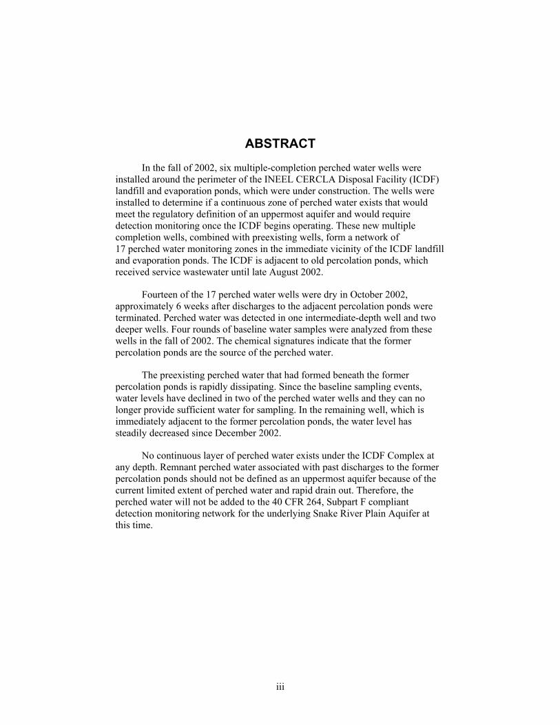
ABSTRACT
In the fall of 2002, six multiple-completion perched water wells were installed around the perimeter of the INEEL CERCLA Disposal Facility (ICDF) landfill and evaporation ponds, which were under construction. The wells were installed to determine if a continuous zone of perched water exists that would meet the regulatory definition of an uppermost aquifer and would require detection monitoring once the ICDF begins operating. These new multiple completion wells, combined with preexisting wells, form a network of 17 perched water monitoring zones in the immediate vicinity of the ICDF landfill and evaporation ponds. The ICDF is adjacent to old percolation ponds, which received service wastewater until late August 2002.
Fourteen of the 17 perched water wells were dry in October 2002, approximately 6 weeks after discharges to the adjacent percolation ponds were terminated. Perched water was detected in one intermediate-depth well and two deeper wells. Four rounds of baseline water samples were analyzed from these wells in the fall of 2002. The chemical signatures indicate that the former percolation ponds are the source of the perched water.
The preexisting perched water that had formed beneath the former percolation ponds is rapidly dissipating. Since the baseline sampling events, water levels have declined in two of the perched water wells and they can no longer provide sufficient water for sampling. In the remaining well, which is immediately adjacent to the former percolation ponds, the water level has steadily decreased since December 2002.
No continuous layer of perched water exists under the ICDF Complex at any depth. Remnant perched water associated with past discharges to the former percolation ponds should not be defined as an uppermost aquifer because of the current limited extent of perched water and rapid drain out. Therefore, the perched water will not be added to the 40 CFR 264, Subpart F compliant detection monitoring network for the underlying Snake River Plain Aquifer at this time.

iv
v
ACKNOWLEDGMENTS
This project could not have been done without the valuable help of numerous people. From the field crews who worked 12-hour shifts 6 days a week all summer to the countless people who checked and entered over 10,000 sample results into the database, their efforts are truly appreciated. While it is not possible to name everyone, we would especially like to thank Kirk Dooley, Dino Lowrey, Gary Oberhansley, Erik Whitmore, Boe Reynolds, Neil Maimer, Joe Cook, Lex Strain, Bob Empey, Lori Lopez, Pat Boyd, Brian Higgs, Don Vernon, Randy Rice, Elita Castleberry, Frank Hight, and the Dynatec drilling crew, Hollie Gilbert, Amy Millward, Jeremy Wall, Dave Hawley, Mike Towler, Brian Twining, Joe Rousseau, Amy Wienke, Donna Kirchner, Corey Harris, Kathy Otter, Howard Johnson, Beth McIlwain, Dave Thompson, Bob Thompson, Jackie Brower, Cheryl Whitaker, Terri Nelson, Pam French, Bruce Culp, Arden Bailey, Mike Ingram, Linda Tedrow, Julie Brizzee, Dan Mahnami, Annie Buttars, Heidi Caye, Larry Hull, Joel Hubbell, Marty Doornbos, Tom Borschel, Jestin Hurst, Meschelle Ransom, Rick Stamps, George Morrison, and Dan Crisp.

vi
vii
CONTENTS
ABSTRACT................................................................................................................................................. iii
ACKNOWLEDGMENTS ............................................................................................................................ v
ACRONYMS................................................................................................................................................ x
1. INTRODUCTION...........................................................................................................................1-1
1.1 Statement of Purpose..........................................................................................................1-1
1.2 Project Background ............................................................................................................1-1
1.3 Regulatory Requirements ...................................................................................................1-3
1.4 Perched Water Wells ..........................................................................................................1-5
2. UPDATED SITE DESCRIPTION ..................................................................................................2-1
2.1 Subsurface Geology............................................................................................................2-1
2.2 Hydrogeology.....................................................................................................................2-8
2.2.1 Surface Water Sources .....................................................................................2-8 2.2.2 Perched Water Formation.................................................................................2-8 2.2.3 Occurrence and Dissipation of Perched Water beneath the ICDF ...................2-9
2.3 Groundwater Chemistry ...................................................................................................2-17
2.3.1 Service Wastewater Chemistry ......................................................................2-17 2.3.2 Baseline Chemistry of New ICDF Perched Water Wells...............................2-20 2.3.3 Chemistry of Drilling Water Supply ..............................................................2-29
3. EFFECT OF THE BIG LOST RIVER ............................................................................................3-1
3.1 Idaho National Engineering and Environmental Laboratory Vadose Zone Research Park and New Percolation Ponds .......................................................................................3-1
3.2 Big Lost River Influence on Idaho Nuclear Technology and Engineering Center Wells .......................................................................................................................3-4
4. CONCLUSIONS AND PATH FORWARD ...................................................................................4-1
4.1 ICDF Perched Water ..........................................................................................................4-1
4.2 Influence of the Big Lost River on the ICDF .....................................................................4-2
4.3 Conclusions ........................................................................................................................4-2
4.4 Path Forward ......................................................................................................................4-3
viii
5. REFERENCES................................................................................................................................5-1
Appendix A Well Completion Report for the ICDF Complex Perched Water Monitoring Well Installations at the Idaho National Engineering and Environmental Laboratory ..........................A-1
Appendix A-A Well Construction Diagrams and Logs for Perched Water Monitoring Wells .............A-15
Appendix A-B Well Completion Forms for ICDF Perched Monitoring Wells ......................................A-33
Appendix B Perched Water Chemistry Data ............................................................................................ B-1
FIGURES
1-1. Location of the ICDF on the Idaho National Engineering and Environmental Laboratory ............1-2
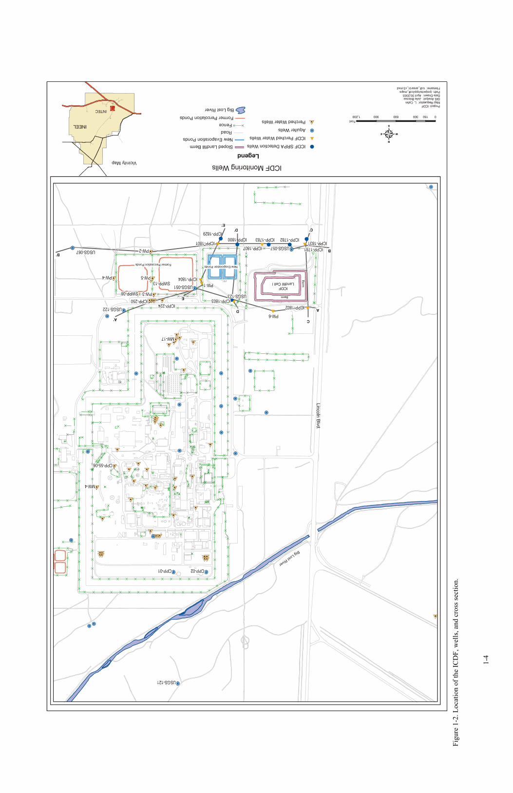
1-2. Location of the ICDF, wells, and cross section ...............................................................................1-4
2-1. East-west cross section A-A′ through wells north of the ICDF ......................................................2-2
2-2. East-west cross sections B-B′ through wells south of the ICDF .....................................................2-3
2-3. North-south cross section C-C′ through wells west of the ICDF ....................................................2-4
2-4. North-south cross section D-D′ through the center of the ICDF Complex .....................................2-5
2-5. North-south cross section E-E′ through wells east of the ICDF......................................................2-6
2-6. Block diagram through the ICDF and the former percolation ponds ..............................................2-7
2-7. Water levels in PW-series perched water wells and flow in the Big Lost River at Lincoln Boulevard. Depth of well is shown on the legend in parentheses .................................................2-10
2-8. Water levels over time in PW-4 and PP-CH-2 ..............................................................................2-11
2-9. Water levels over time for Well ICPP-1804M ..............................................................................2-12
2-10. Neutron logs of Well USGS-51.....................................................................................................2-14
2-11. Water levels over time for Well ICPP-1804L ...............................................................................2-15
2-12. Water levels over time for Well ICPP-1807L ...............................................................................2-16
2-13. Schoeller diagram of water quality in the Idaho Nuclear Technology and Engineering Center vicinity for perched water, service wastewater, the Snake River Plain Aquifer, and the Big Lost River ......................................................................................................................................2-19
2-14. Tritium, chloride, and Sr-90 trends for PW-1 ...............................................................................2-21
2-15. Chloride concentrations from ICDF perched water wells .............................................................2-22
ix
2-16. Piper diagram for the ICDF perched water wells, nearby perched water wells, and other sources..................................................................................................................................2-23
2-17. Strontium-90 concentrations from ICDF perched water wells......................................................2-25
2-18. Iodine-129 concentrations from ICDF perched water wells..........................................................2-26
2-19. Tritium concentrations from ICDF perched wells.........................................................................2-27
2-20. Plan map of the Idaho Nuclear Technology and Engineering Center showing tritium concentrations in perched water wells (2001) ...............................................................................2-28
3-1. Well locations at the Vadose Zone Research Park and the new Idaho Nuclear Technology and Engineering Center percolation ponds ............................................................................................3-2
TABLES
1-1. The ICDF Complex groundwater monitoring applicable or relevant and appropriate requirements ....................................................................................................................................1-3
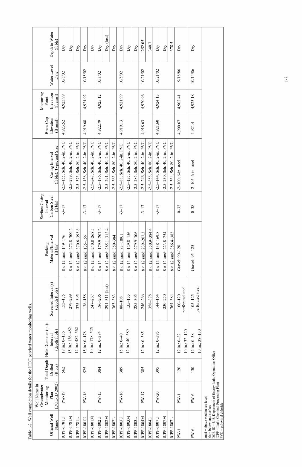
1-2. Well completion details for the ICDF perched water monitoring wells..........................................1-7
x
ACRONYMS
amsl above median sea level
ARAR applicable or relevant and appropriate requirement
bls below land surface
CERCLA Comprehensive Environmental Response, Compensation and Liability Act
CFR Code of Federal Regulations
DEQ Idaho Department of Environmental Quality
DOE-ID U.S. Department of Energy Idaho Operations Office
DR dual rotary
EPA U.S. Environmental Protection Agency
ICDF INEEL CERCLA Disposal Facility
ICPP Idaho Chemical Processing Plant
INEEL Idaho National Engineering and Environmental Laboratory
INTEC Idaho Nuclear Technology and Engineering Center
MCL maximum contaminant level
PVC polyvinyl chloride
PW perched water
RCRA Resource Conservation and Recovery Act
SRPA Snake River Plain Aquifer
TEGD technical enforcement guidance document
USGS United States Geological Survey
VZRP Vadose Zone Research Park
1-1
Analysis of Perched Water Data from ICDF Monitoring Wells
1. INTRODUCTION
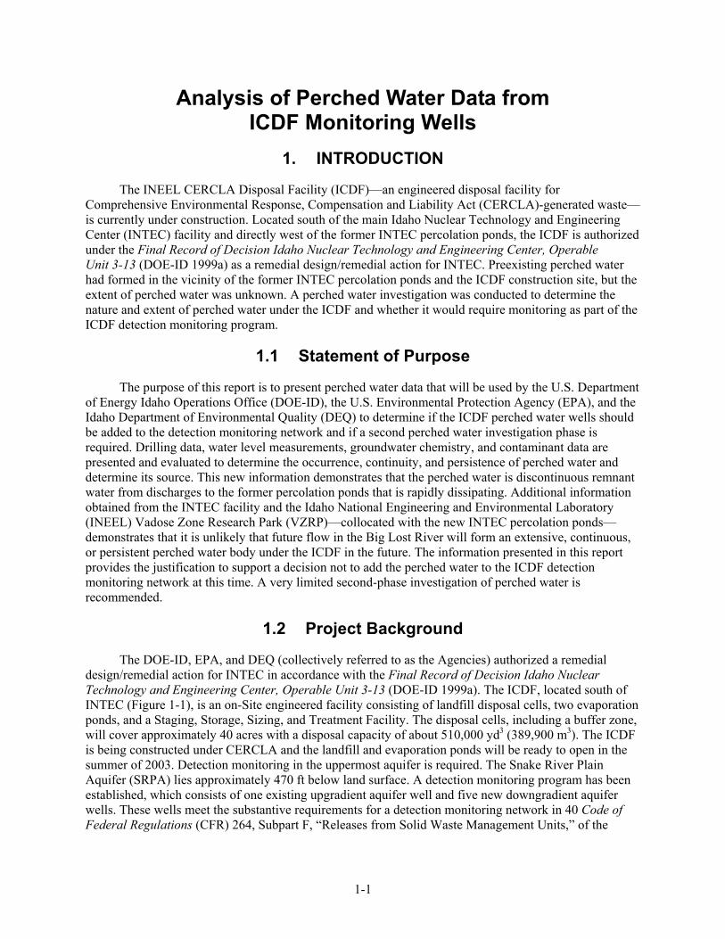
The INEEL CERCLA Disposal Facility (ICDF)—an engineered disposal facility for Comprehensive Environmental Response, Compensation and Liability Act (CERCLA)-generated waste—is currently under construction. Located south of the main Idaho Nuclear Technology and Engineering Center (INTEC) facility and directly west of the former INTEC percolation ponds, the ICDF is authorized under the Final Record of Decision Idaho Nuclear Technology and Engineering Center, Operable Unit 3-13 (DOE-ID 1999a) as a remedial design/remedial action for INTEC. Preexisting perched water had formed in the vicinity of the former INTEC percolation ponds and the ICDF construction site, but the extent of perched water was unknown. A perched water investigation was conducted to determine the nature and extent of perched water under the ICDF and whether it would require monitoring as part of the ICDF detection monitoring program.
1.1 Statement of Purpose
The purpose of this report is to present perched water data that will be used by the U.S. Department of Energy Idaho Operations Office (DOE-ID), the U.S. Environmental Protection Agency (EPA), and the Idaho Department of Environmental Quality (DEQ) to determine if the ICDF perched water wells should be added to the detection monitoring network and if a second perched water investigation phase is required. Drilling data, water level measurements, groundwater chemistry, and contaminant data are presented and evaluated to determine the occurrence, continuity, and persistence of perched water and determine its source. This new information demonstrates that the perched water is discontinuous remnant water from discharges to the former percolation ponds that is rapidly dissipating. Additional information obtained from the INTEC facility and the Idaho National Engineering and Environmental Laboratory (INEEL) Vadose Zone Research Park (VZRP)—collocated with the new INTEC percolation ponds—demonstrates that it is unlikely that future flow in the Big Lost River will form an extensive, continuous, or persistent perched water body under the ICDF in the future. The information presented in this report provides the justification to support a decision not to add the perched water to the ICDF detection monitoring network at this time. A very limited second-phase investigation of perched water is recommended.
1.2 Project Background
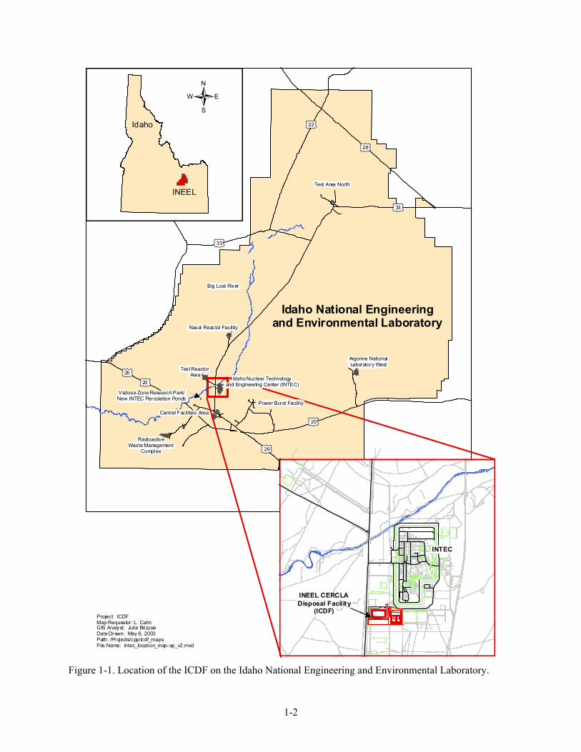
The DOE-ID, EPA, and DEQ (collectively referred to as the Agencies) authorized a remedial design/remedial action for INTEC in accordance with the Final Record of Decision Idaho Nuclear Technology and Engineering Center, Operable Unit 3-13 (DOE-ID 1999a). The ICDF, located south of INTEC (Figure 1-1), is an on-Site engineered facility consisting of landfill disposal cells, two evaporation ponds, and a Staging, Storage, Sizing, and Treatment Facility. The disposal cells, including a buffer zone, will cover approximately 40 acres with a disposal capacity of about 510,000 yd3 (389,900 m3). The ICDF is being constructed under CERCLA and the landfill and evaporation ponds will be ready to open in the summer of 2003. Detection monitoring in the uppermost aquifer is required. The Snake River Plain Aquifer (SRPA) lies approximately 470 ft below land surface. A detection monitoring program has been established, which consists of one existing upgradient aquifer well and five new downgradient aquifer wells. These wells meet the substantive requirements for a detection monitoring network in 40 Code of Federal Regulations (CFR) 264, Subpart F, “Releases from Solid Waste Management Units,” of the
1-2
tu
tu
tu
tu
tu
tu
tu
tu20
28
22
33
33
20
26
26
}
}
} }
}
} }} }
} }}
}
} }}}
} }}}}
}
}
} }} }} }
}}
} }} }} }}}
}
} } }
}
}
}
} }
}
}} }
}
}
}
} }}
}
}}}
}}
}
} }}}}
}}}
} }}}
}}
}}
} } } }
}}
}}
}
}}
} }
}
} }}
} }} }}} }
} }
} }}
}}
}}
} }}
}
}}}}
}} }}}}}} } }}
}} }
} }
} }}}} }
}
}
} }
}
} }
}
}
}
}
}}
}
}
} }
}
}
}} } }
}
}
}}
}
}}
}}}
}}}
}}
}
}}
}}
} } }} }}
}}
}}
} } }
}
} }}
}
}}
}}}}}}
} }}
}}
} }}
}}
} } }
}}
}}
Idaho
INEEL
Idaho National Engineeringand Environmental Laboratory
Test Area North
Naval Reactor Facility
Test Reactor Area
Idaho Nuclear Technologyand Engineering Center (INTEC)
Power Burst Facility
RadioactiveWaste Management
Complex
INTEC
Central Facilities Area
Big Lost River
Argonne NationalLaboratory West
Project: ICDFMap Requestor: L. CahnGIS Analyst: Julie BrizzeeDate Drawn: May 6, 2003Path: /Projects/cpp/icdf_mapsFile Name: intec_location_map-ap_v2.mxd
INEEL CERCLADisposal Facility
(ICDF)
{
Vadose Zone Research Park/New INTEC Percolation Ponds
Figure 1-1. Location of the ICDF on the Idaho National Engineering and Environmental Laboratory.
1-3
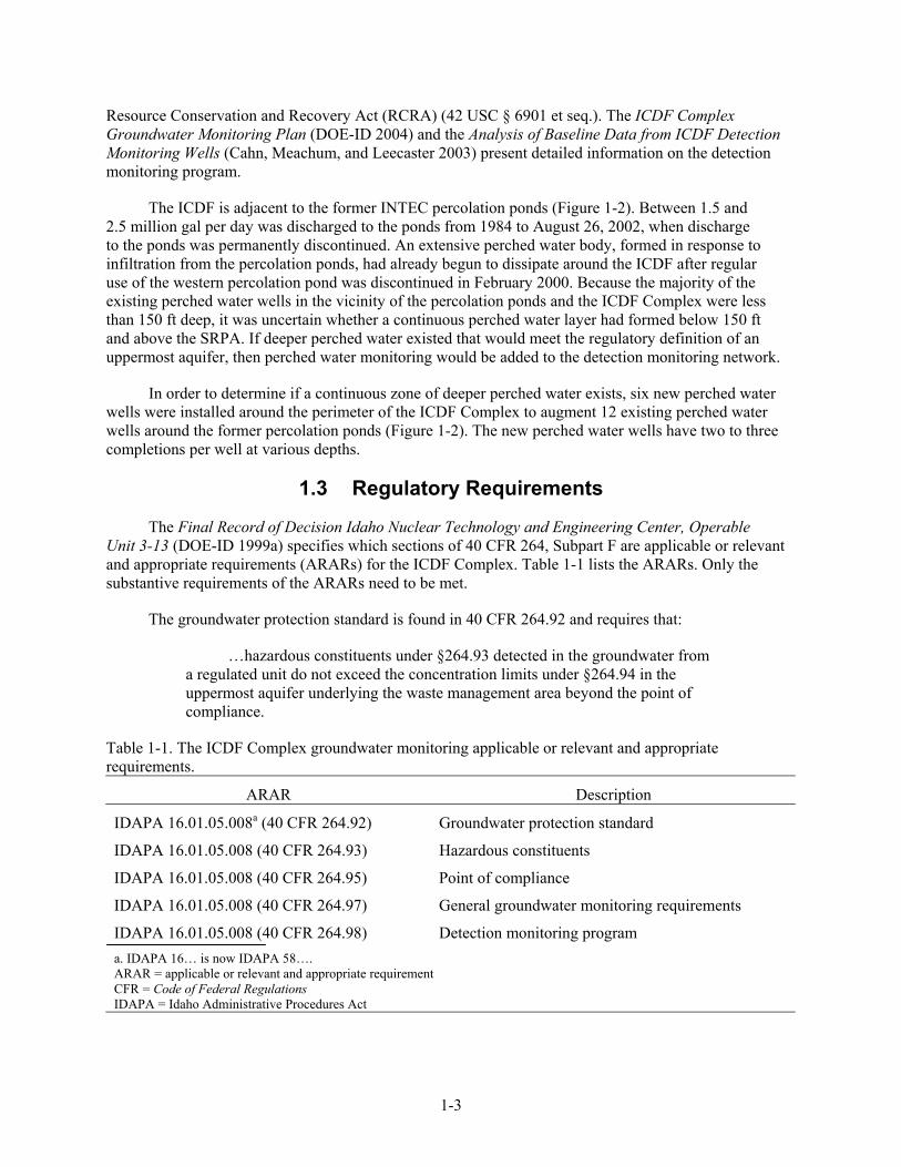
Resource Conservation and Recovery Act (RCRA) (42 USC § 6901 et seq.). The ICDF Complex Groundwater Monitoring Plan (DOE-ID 2004) and the Analysis of Baseline Data from ICDF Detection Monitoring Wells (Cahn, Meachum, and Leecaster 2003) present detailed information on the detection monitoring program.
The ICDF is adjacent to the former INTEC percolation ponds (Figure 1-2). Between 1.5 and 2.5 million gal per day was discharged to the ponds from 1984 to August 26, 2002, when discharge to the ponds was permanently discontinued. An extensive perched water body, formed in response to infiltration from the percolation ponds, had already begun to dissipate around the ICDF after regular use of the western percolation pond was discontinued in February 2000. Because the majority of the existing perched water wells in the vicinity of the percolation ponds and the ICDF Complex were less than 150 ft deep, it was uncertain whether a continuous perched water layer had formed below 150 ft and above the SRPA. If deeper perched water existed that would meet the regulatory definition of an uppermost aquifer, then perched water monitoring would be added to the detection monitoring network.
In order to determine if a continuous zone of deeper perched water exists, six new perched water wells were installed around the perimeter of the ICDF Complex to augment 12 existing perched water wells around the former percolation ponds (Figure 1-2). The new perched water wells have two to three completions per well at various depths.
1.3 Regulatory Requirements
The Final Record of Decision Idaho Nuclear Technology and Engineering Center, Operable Unit 3-13 (DOE-ID 1999a) specifies which sections of 40 CFR 264, Subpart F are applicable or relevant and appropriate requirements (ARARs) for the ICDF Complex. Table 1-1 lists the ARARs. Only the substantive requirements of the ARARs need to be met.
The groundwater protection standard is found in 40 CFR 264.92 and requires that:
…hazardous constituents under §264.93 detected in the groundwater from a regulated unit do not exceed the concentration limits under §264.94 in the uppermost aquifer underlying the waste management area beyond the point of compliance.
Table 1-1. The ICDF Complex groundwater monitoring applicable or relevant and appropriate requirements.
ARAR Description
IDAPA 16.01.05.008a (40 CFR 264.92) Groundwater protection standard
IDAPA 16.01.05.008 (40 CFR 264.93) Hazardous constituents
IDAPA 16.01.05.008 (40 CFR 264.95) Point of compliance
IDAPA 16.01.05.008 (40 CFR 264.97) General groundwater monitoring requirements
IDAPA 16.01.05.008 (40 CFR 264.98) Detection monitoring program a. IDAPA 16… is now IDAPA 58…. ARAR = applicable or relevant and appropriate requirement CFR = Code of Federal Regulations IDAPA = Idaho Administrative Procedures Act
1-
4
Fi
gure
1-2
. Loc
atio
n of
the
ICD
F, w
ells
, and
cro
ss se
ctio
n.
1-5
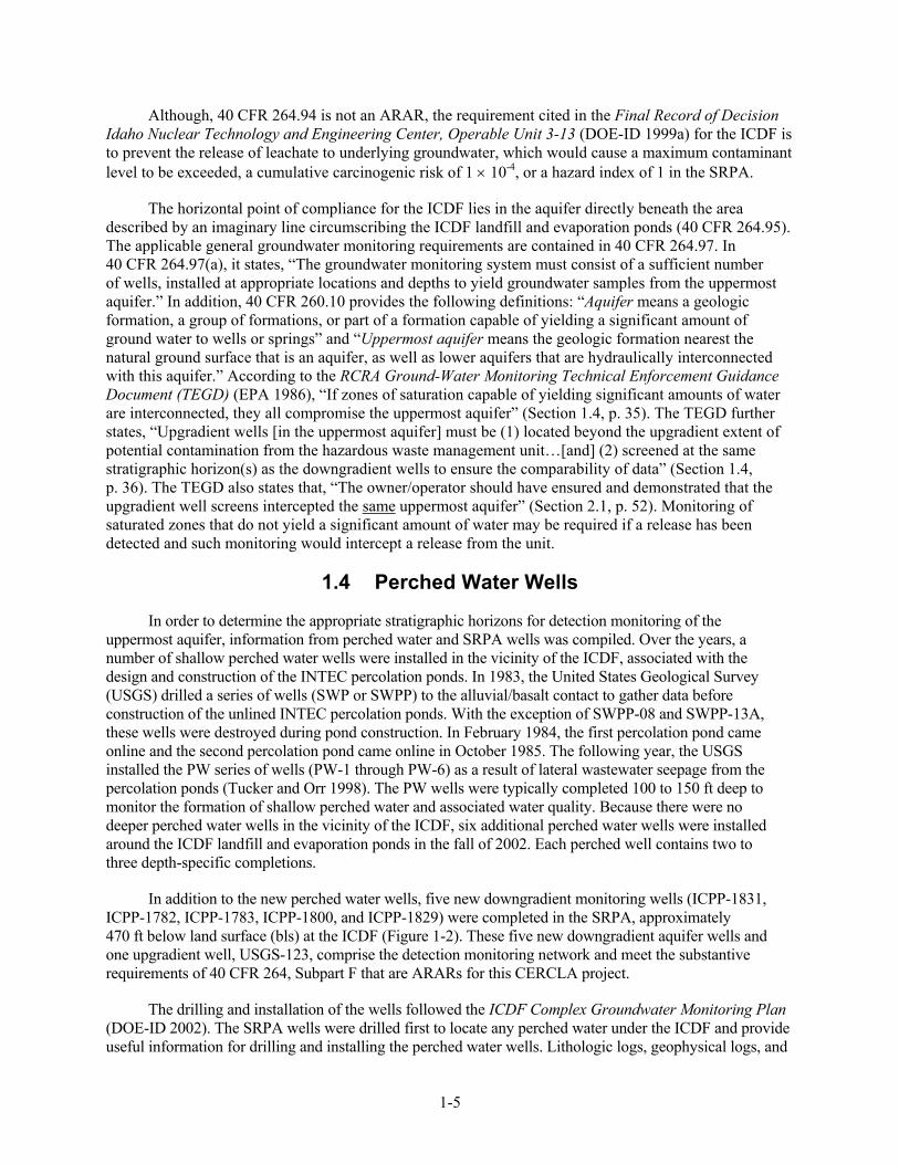
Although, 40 CFR 264.94 is not an ARAR, the requirement cited in the Final Record of Decision Idaho Nuclear Technology and Engineering Center, Operable Unit 3-13 (DOE-ID 1999a) for the ICDF is to prevent the release of leachate to underlying groundwater, which would cause a maximum contaminant level to be exceeded, a cumulative carcinogenic risk of 1 × 10⁻⁴, or a hazard index of 1 in the SRPA.
The horizontal point of compliance for the ICDF lies in the aquifer directly beneath the area described by an imaginary line circumscribing the ICDF landfill and evaporation ponds (40 CFR 264.95). The applicable general groundwater monitoring requirements are contained in 40 CFR 264.97. In 40 CFR 264.97(a), it states, “The groundwater monitoring system must consist of a sufficient number of wells, installed at appropriate locations and depths to yield groundwater samples from the uppermost aquifer.” In addition, 40 CFR 260.10 provides the following definitions: “Aquifer means a geologic formation, a group of formations, or part of a formation capable of yielding a significant amount of ground water to wells or springs” and “Uppermost aquifer means the geologic formation nearest the natural ground surface that is an aquifer, as well as lower aquifers that are hydraulically interconnected with this aquifer.” According to the RCRA Ground-Water Monitoring Technical Enforcement Guidance Document (TEGD) (EPA 1986), “If zones of saturation capable of yielding significant amounts of water are interconnected, they all compromise the uppermost aquifer” (Section 1.4, p. 35). The TEGD further states, “Upgradient wells [in the uppermost aquifer] must be (1) located beyond the upgradient extent of potential contamination from the hazardous waste management unit…[and] (2) screened at the same stratigraphic horizon(s) as the downgradient wells to ensure the comparability of data” (Section 1.4, p. 36). The TEGD also states that, “The owner/operator should have ensured and demonstrated that the upgradient well screens intercepted the same uppermost aquifer” (Section 2.1, p. 52). Monitoring of saturated zones that do not yield a significant amount of water may be required if a release has been detected and such monitoring would intercept a release from the unit.
1.4 Perched Water Wells
In order to determine the appropriate stratigraphic horizons for detection monitoring of the uppermost aquifer, information from perched water and SRPA wells was compiled. Over the years, a number of shallow perched water wells were installed in the vicinity of the ICDF, associated with the design and construction of the INTEC percolation ponds. In 1983, the United States Geological Survey (USGS) drilled a series of wells (SWP or SWPP) to the alluvial/basalt contact to gather data before construction of the unlined INTEC percolation ponds. With the exception of SWPP-08 and SWPP-13A, these wells were destroyed during pond construction. In February 1984, the first percolation pond came online and the second percolation pond came online in October 1985. The following year, the USGS installed the PW series of wells (PW-1 through PW-6) as a result of lateral wastewater seepage from the percolation ponds (Tucker and Orr 1998). The PW wells were typically completed 100 to 150 ft deep to monitor the formation of shallow perched water and associated water quality. Because there were no deeper perched water wells in the vicinity of the ICDF, six additional perched water wells were installed around the ICDF landfill and evaporation ponds in the fall of 2002. Each perched well contains two to three depth-specific completions.
In addition to the new perched water wells, five new downgradient monitoring wells (ICPP-1831, ICPP-1782, ICPP-1783, ICPP-1800, and ICPP-1829) were completed in the SRPA, approximately 470 ft below land surface (bls) at the ICDF (Figure 1-2). These five new downgradient aquifer wells and one upgradient well, USGS-123, comprise the detection monitoring network and meet the substantive requirements of 40 CFR 264, Subpart F that are ARARs for this CERCLA project.
The drilling and installation of the wells followed the ICDF Complex Groundwater Monitoring Plan (DOE-ID 2002). The SRPA wells were drilled first to locate any perched water under the ICDF and provide useful information for drilling and installing the perched water wells. Lithologic logs, geophysical logs, and
1-6
completion details of the SRPA wells are located in Appendix A of the Analysis of Baseline Data from ICDF Detection Monitoring Wells (Cahn, Meachum, and Leecaster 2003).
The perched water wells were completed with two to three screened intervals in each well. The multiple completion zones are designated U for upper completion, M for middle completion, and L for lower completion after the well name. Well completion reports for the perched water wells are located in Appendix A of this document. Additional information provided includes rationale for field decisions and determination of screened intervals. Appendix A-A contains detailed lithologic logs, geophysical logs, and well completion diagrams. Appendix A-B contains well completion forms. Table 1-2 summarizes well completion details.
1-
7
Tabl
e 1-
2. W
ell c
ompl
etio
n de
tails
for t
he IC
DF
perc
hed
wat
er m
onito
ring
wel
ls.
Off
icia
l Wel
l N
ame
Wel
l Nam
e in
G
roun
dwat
er
Mon
itorin
g Pl
an
(DO
E-ID
200
2) To
tal D
epth
D
rille
d (f
t bls
)
Hol
e D
iam
eter
(in.
): In
terv
al
(dep
th ft
bls
) Sc
reen
ed In
terv
al(s
) (d
epth
ft b
ls)
Pack
ing
Mat
eria
l/Int
erva
l (f
t bls
)
Surf
ace
Cas
ing
Inte
rval
C
arbo
n St
eel
(ft b
ls)
Cas
ing
Inte
rval
(f
t bls
), Ty
pe, a
nd S
ize
Bra
ss C
ap
Elev
atio
n
(ft a
msl
)
Mea
surin
g Po
int
Elev
atio
n (f
t am
sl)
Wat
er L
evel
D
ate
Dep
th to
Wat
er
(ft b
ls)
ICPP
-178
1U
155–
175
8 ×
12 sa
nd: 1
49–1
76
-2.5
–155
, Sch
. 40,
2-in
. PV
C
Dry
ICPP
-178
1M
279–
299
8 ×
12 sa
nd: 2
72.8
–300
.2
-2.5
–279
, Sch
. 40,
2-in
. PV
C
Dry
ICPP
-178
1L
PW-1
9 56
2 19
in.:
0–13
6 15
in.:
136–
482
12 in
.: 48
2–56
2 37
5–39
5 8
× 12
sand
: 370
.6–3
95.8
-3–1
7
-2.5
–375
, Sch
. 80,
2-in
. PV
C
4,92
3.52
4,
925.
99
10/3
/02
Dry
ICPP
-180
1U
138–
158
8 ×
12 sa
nd: 1
35–1
59
-2.5
–138
, Sch
. 40,
2-in
. PV
C
Dry
ICPP
-180
1M
PW-1
8 52
5 15
in.:
0–17
8 10
in.:
178–
525
247–
267
8 ×
12 sa
nd: 2
40.8
–268
.5
-3–1
7
-2.5
–247
, Sch
. 40,
2-in
. PV
C
4,91
9.68
4,
921.
92
10/1
5/02
Dry
ICPP
-180
2U
186–
206
8 ×
12 sa
nd: 1
79.9
–207
.2
-2.5
–186
, Sch
. 40,
2-in
. PV
C
Dry
ICPP
-180
2M
291–
311
(lost
) 8
× 12
sand
: 285
.1–3
12.4
-2
.5–2
91, S
ch. 4
0, 2
-in. P
VC
D
ry (l
ost)
ICPP
-180
2L
PW-1
5 38
4 12
in.:
0–38
4
363–
383
8 ×
12 sa
nd: 3
50–3
84
-3–1
7
-2.5
–363
, Sch
. 80,
2-in
. PV
C
4,92
2.79
4,
925.
12
10/3
/02
Dry
ICPP
-180
3U
88–1
08
8 ×
12 sa
nd: 8
3–10
9.1
-2.5
–88,
Sch
. 40,
2-in
. PV
C
Dry
ICPP
-180
3M
135–
155
8 ×
12 sa
nd: 1
29.8
–156
-2
.5–1
35, S
ch. 4
0, 2
-in. P
VC
D
ry
ICPP
-180
3L
PW-1
6 38
9 15
in.:
0–40
12
in.:
40–3
89
285–
305
8 ×
12 sa
nd: 2
79.9
–306
-3–1
7
-2.5
–285
, Sch
. 80,
2-in
. PV
C
4,91
9.13
4,
921.
99
10/5
/02
Dry
ICPP
-180
4M
246–
266
8 ×
12 sa
nd: 2
39–2
67.3
-2
.5–2
46, S
ch. 4
0, 2
-in. P
VC
25
2.05
ICPP
-180
4L
PW-1
7 38
5 12
in.:
0–38
5
358–
378
8 ×
12 sa
nd: 3
50.9
–384
.4
-3–1
7
-2.5
–358
, Sch
. 80,
2-in
. PV
C
4,91
8.63
4,
920.
96
10/2
1/02
340.
7
ICPP
-180
7U
144–
164
8 ×
12 sa
nd: 1
38–1
69.8
-2
.5–1
44, S
ch. 4
0, 2
-in. P
VC
D
ry
ICPP
-180
7M
230–
250
8 ×
12 sa
nd: 2
23.8
–254
-2
.5–2
30, S
ch. 4
0, 2
-in. P
VC
D
ry
ICPP
-180
7L
PW-2
0 39
5 12
in.:
0–39
5
364–
384
8 ×
12 sa
nd: 3
56.4
–385
-3–1
7
-2.5
–364
, Sch
. 80,
2-in
. PV
C
4,92
1.60
4,
924.
13
10/2
1/02
378.
5
PW-1
PW
-1
120
12 in
.: 0–
32
10 in
.: 32
–120
10
0–12
0
p
erfo
rate
d st
eel
Gra
vel:
90–1
20
0–32
-2
–100
, 6-in
. ste
el
4,90
0.67
4,
902.
41
9/1
8/86
D
ry
PW-6
PW
-6
130
12 in
.: 0–
38
10 in
.: 38
–130
10
5–12
5
p
erfo
rate
d st
eel
Gra
vel:
95–1
25
0–38
-2
–105
, 6-in
. ste
el
4,92
1.4
4,92
3.18
10
/14/
86
Dry
amsl
= a
bove
med
ian
sea
leve
l bl
s = b
elow
land
surf
ace
DO
E-ID
= U
.S. D
epar
tmen
t of E
nerg
y Id
aho
Ope
ratio
ns O
ffic
e IC
PP =
Idah
o C
hem
ical
Pro
cess
ing
Plan
t PV
C =
pol
yvin
yl c
hlor
ide

1-8