Embed Size (px)
Citation preview
H. Azechi
Institute of Laser EngineeringOsaka University
2011.6.15Prospects for Inertial Confinement Fusion Energy SystemsNational Academies
ILE OSAKA
1
Inertial Fusion Energy: Activities and Plans in Japan
Haunting face crying a river of tears as glacier melts into the seaPhoto By Michael Norman
Many people die every summer throughout the world. In last Japanese summer, more than 50 thousand people were taken to hospitals and 172 people died. Global warming is real and cannot wait. This picture is a haunting face crying a river of tears as glacier melts in the see and is used as a symbol of global warming. Fission energy has been recognized as one of primary solutions to the global worming. Fusion has long been considered as only a potential option in future. But Fukushima-Daiichi disaster will change this conservative view if strong fusion solution exists
ILE OSAKA
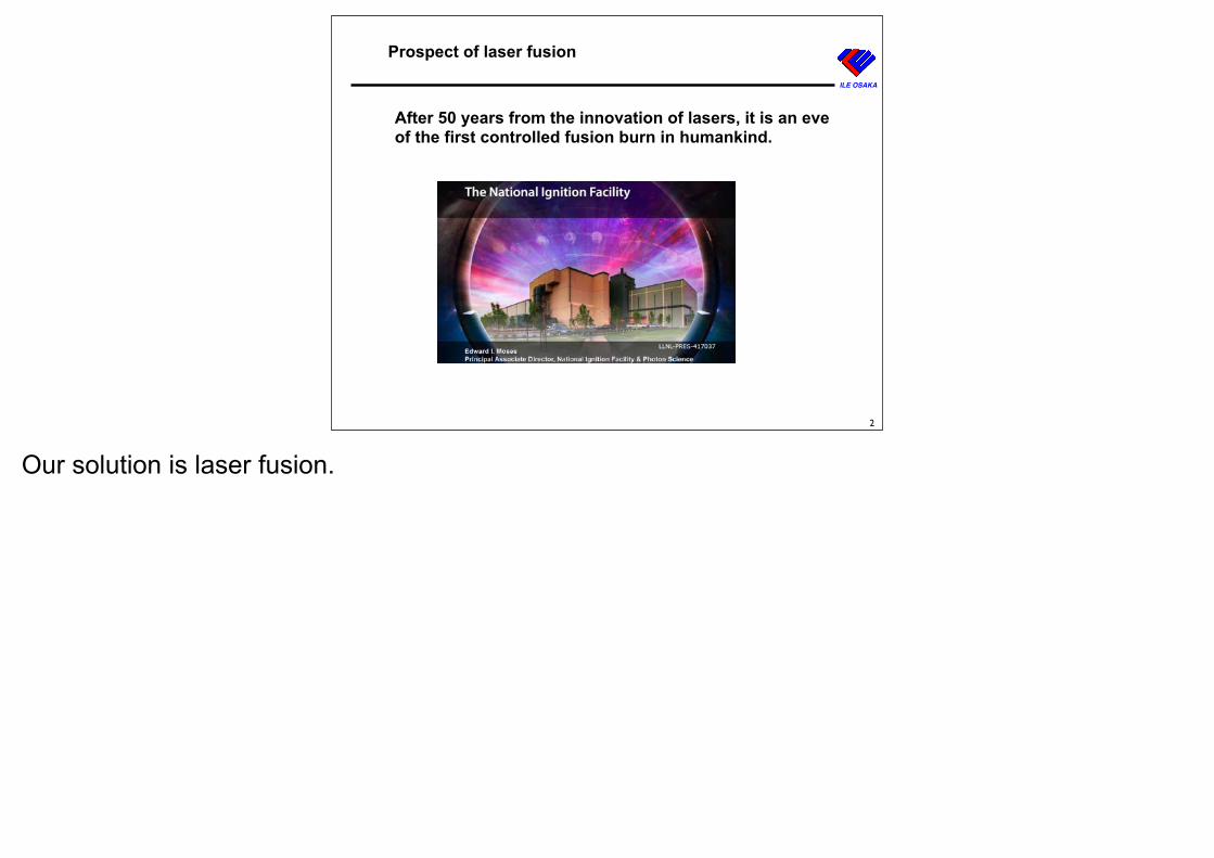
After 50 years from the innovation of lasers, it is an eve of the first controlled fusion burn in humankind.
Prospect of laser fusion
2
Our solution is laser fusion.
ILE OSAKA
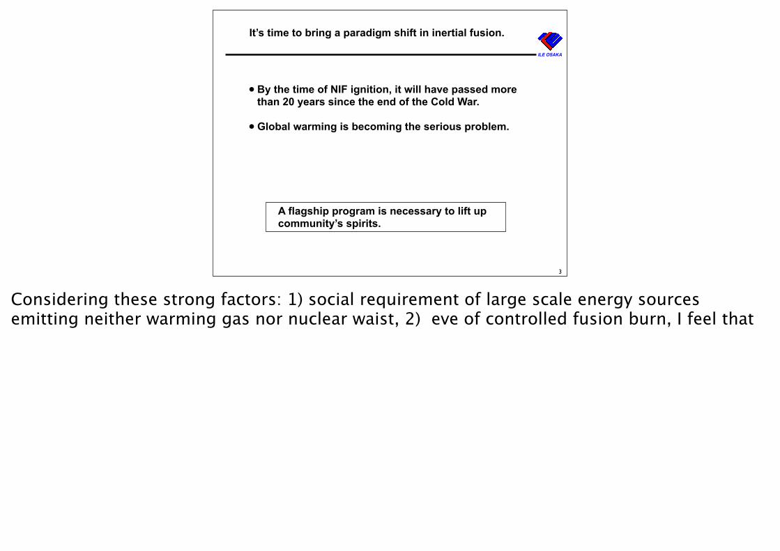
It’s time to bring a paradigm shift in inertial fusion.
• By the time of NIF ignition, it will have passed more than 20 years since the end of the Cold War.
• Global warming is becoming the serious problem.
3
A flagship program is necessary to lift up community’s spirits.
Considering these strong factors: 1) social requirement of large scale energy sources emitting neither warming gas nor nuclear waist, 2) eve of controlled fusion burn, I feel that
ILE OSAKA
12
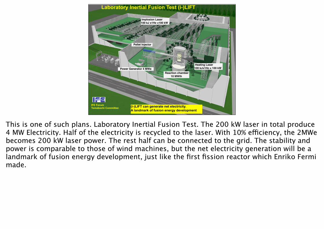
Implosion Laser100 kJ x1Hz =100 kW
Reaction chamber10 MWth
Heating Laser 100 kJx1Hz = 100 kW
Pellet Injector
Power Generator 4 MWe
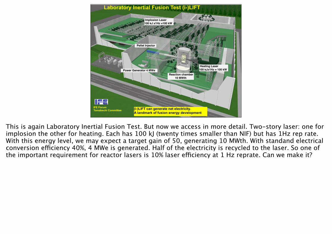
Laboratory Inertial Fusion Test (i-)LIFT
IFE ForumTomabechi Committee (i-)LIFT can generate net electricity.
A landmark of fusion energy development
This is one of such plans. Laboratory Inertial Fusion Test. The 200 kW laser in total produce 4 MW Electricity. Half of the electricity is recycled to the laser. With 10% efficiency, the 2MWe becomes 200 kW laser power. The rest half can be connected to the grid. The stability and power is comparable to those of wind machines, but the net electricity generation will be a landmark of fusion energy development, just like the first fission reactor which Enriko Fermi made.
核融合原型炉
Experimental reactor (i-)LIFT integrates all physics and engineering activities.
◆ Power generation demonstration Judge: DEMO Const.
▲ Commercial demonstration
Demonstration PlantDEMO
200kJ/1Hz
Eng.Design
ConceptDesign
Eng. Design
(i-)LIFT is Laser based Fast Track. 09/11/7
ILE OSAKA
19
Implosion Laser
100 kJ x1Hz =100 kW
Reaction chamber
10 MWth
Heating Laser
100 kJx1Hz = 100 kW
Pellet Injector
Power Generator 4 MWe
IFEForum
Committee of Inertial Fusion Energy
Development
International Laboratory Inertial Fusion Test
IFE Forum
NIF (US)
FIREX-I (Jpn), EP
▲ Ignition
10 15 4025 30 35 20
1-month operation
Power plant technology, ESE issues
Fusion chamber, Blanket
Target fab., Injection, Tracking
Driver development
45
Reactor technology Elements
Advanced reactor technology
Reactor Core Plasma Physics
10 J/1Hz
◆ Ignition
ILE OSAKA
1 kJ/1Hz x 10
◆Ignition TempJudge: FIREX-II & Eng. Design
FIREX-II ▲ Fast Ignition
1.2 MJ/4Hz1 Reaction Chamber
SGIV (China)LMJ (France) ▲ Ignition
1J/1Hz
10min BurstSingle shot
Blanket test
Experimental ReactorLIFT
Integrated Engineering
Test
Continuity Endurance
◆ Repeated core plasma Judge: LIFT Const.
1.2 MJ/16 Hz4 Reaction Chamber
Commercial Plant
Construction:2-3 B$
Construction:3-4 B$
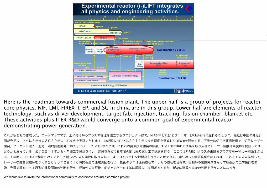
Here is the roadmap towards commercial fusion plant. The upper half is a group of projects for reactor core physics. NIF, LMJ, FIREX-I, EP, and SG in china are in this group. Lower half are elements of reactor technology, such as driver development, target fab, injection, tracking, fusion chamber, blanket etc. These activities plus ITER R&D would converge onto a common goal of experimental reactor demonstrating power generation. これが私どもの作成した,ロードマップです.上半分は炉心プラズマ物理を確立するプロジェクト群で,NIFが早ければ2011年,LMJがそれに遅れること5年,最近は中国の神光計画が発足し,さらに5年後の2020年に中心点火を実証いたします.わが国のFIREXは2011年に点火温度を達成しFIREX-IIを開始する.下半分は炉工学要素技術で,炉用レーザー開発,ターゲット注入・追尾・照射技術開発,炉チャンバー・ブランケットなどです.これらの要素技術開発の成果,およびITER&Dの成果を取り入れてレーザー核融合実験炉を開始してはどうかと思っている.まず2011年から4年間工学設計を行い,建設を含めて5年間の間に繰り返し工学試験を行う.ここではFIREX−Iクラスの未臨界プラズマを一秒に一回発生させる.その間にFIREX-IIで検証されるであろう新しい知見を柔軟に取り入れて,よりコンパクトな炉開発を行うことができる.繰り返し工学試験が成功すれば,それをそのまま拡張して,レーザー核融合実験炉をつくり2030年ごろに10時間程度の発電実証を行う.最後の3年は連続運転で1ヶ月の運転を目指す.実験炉の装置完成をもって原型炉の工学設計を開始,発電実証をもって原型炉建設開始の判断を行う.経済性の実証後,炉チャンバーを4基に増設し,実用炉とするか,新たに建設するかの判断を行うことになろう.
We would like to invite the international community to coordinate around a common project
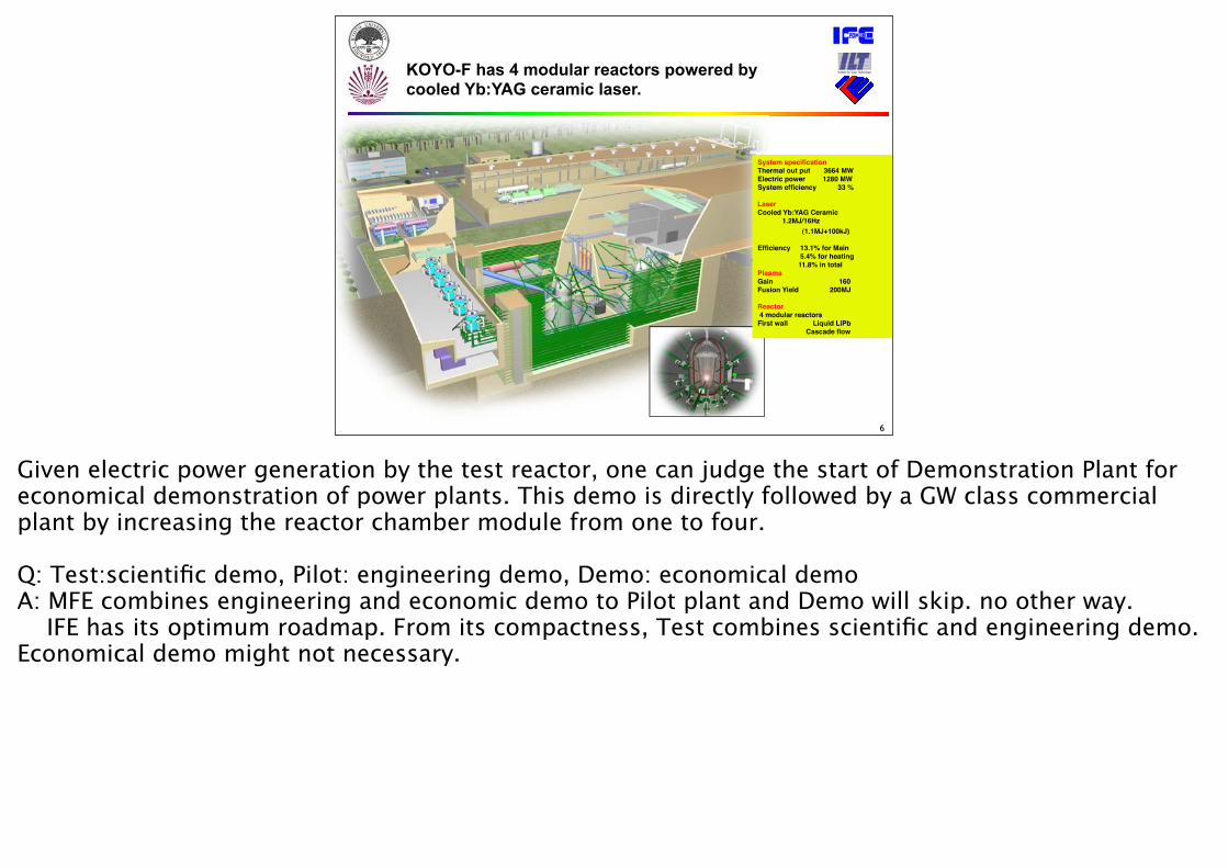
KOYO-F has 4 modular reactors powered by cooled Yb:YAG ceramic laser.
System specificationThermal out put 3664 MWElectric power 1280 MWSystem efficiency 33 %
LaserCooled Yb:YAG Ceramic����������� 1.2MJ/16Hz (1.1MJ+100kJ) Efficiency 13.1% for Main 5.4% for heating 11.8% in totalPlasmaGain 160Fusion Yield 200MJ
Reactor 4 modular reactorsFirst wall Liquid LiPb Cascade flow
6
Given electric power generation by the test reactor, one can judge the start of Demonstration Plant for economical demonstration of power plants. This demo is directly followed by a GW class commercial plant by increasing the reactor chamber module from one to four.
Q: Test:scientific demo, Pilot: engineering demo, Demo: economical demoA: MFE combines engineering and economic demo to Pilot plant and Demo will skip. no other way. IFE has its optimum roadmap. From its compactness, Test combines scientific and engineering demo. Economical demo might not necessary.
ILE OSAKA
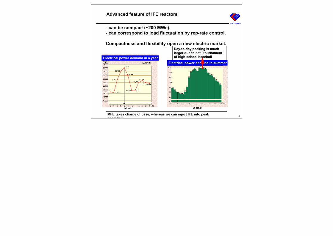
Advanced feature of IFE reactors
- can be compact (~200 MWe).- can correspond to load fluctuation by rep-rate control.
Compactness and flexibility open a new electric market.
7MFE takes charge of base, whereas we can inject IFE into peak operation.
O’clock
Electrical power demand in summerElectrical power demand in a year
Month
Day-to-day peaking is much larger due to nat’l tournament of high-school baseball
Are we ready?
8
PlasmaLaserTargetReactor
Alliance
Question arises “are we ready?” on Plasma physics, Laser, target and reactor development plus alliance with other people inc. industries. Concerning the burning plasma creation, the remaining issue is how we can downsize the reactor core plasma.
ILE OSAKA
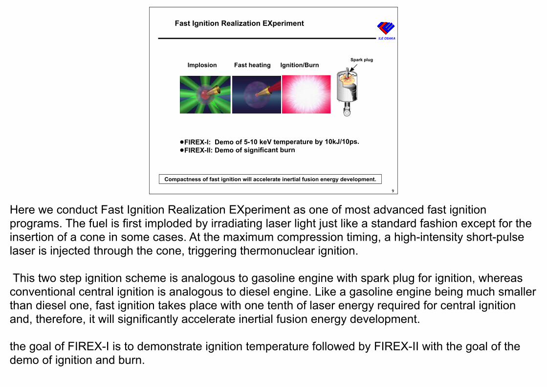
Fast Ignition Realization EXperiment
9
Implosion Fast heating Ignition/BurnSpark plug
Compactness of fast ignition will accelerate inertial fusion energy development.
•FIREX-I: Demo of 5-10 keV temperature by 10kJ/10ps. •FIREX-II: Demo of significant burn
Here we conduct Fast Ignition Realization EXperiment as one of most advanced fast ignition programs. The fuel is first imploded by irradiating laser light just like a standard fashion except for the insertion of a cone in some cases. At the maximum compression timing, a high-intensity short-pulse laser is injected through the cone, triggering thermonuclear ignition.
This two step ignition scheme is analogous to gasoline engine with spark plug for ignition, whereas conventional central ignition is analogous to diesel engine. Like a gasoline engine being much smaller than diesel one, fast ignition takes place with one tenth of laser energy required for central ignition and, therefore, it will significantly accelerate inertial fusion energy development.
the goal of FIREX-I is to demonstrate ignition temperature followed by FIREX-II with the goal of the demo of ignition and burn.
GEKKO-IV ’77
GEKKO-II ’73
GEKKO-MII ’79
GEKKO-XII 1983
PetaWatt1996-2001
ILE OSAKA
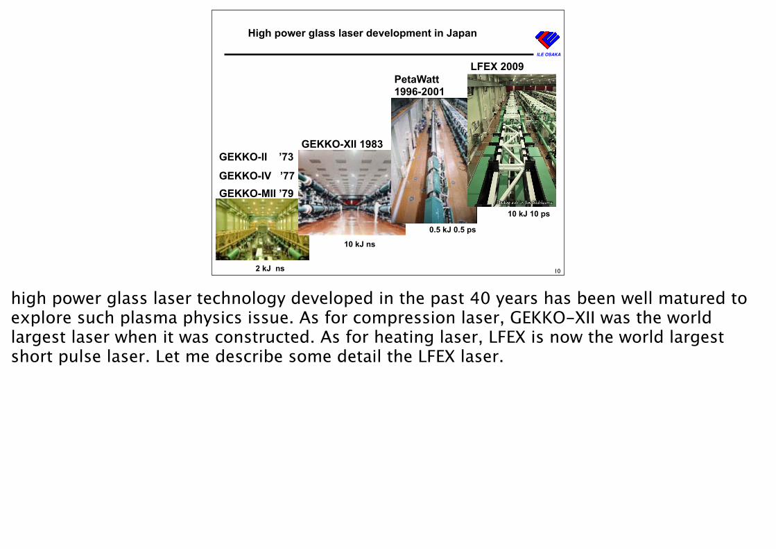
High power glass laser development in Japan
10
LFEX 2009
0.5 kJ 0.5 ps
10 kJ 10 ps
10 kJ ns
2 kJ ns
high power glass laser technology developed in the past 40 years has been well matured to explore such plasma physics issue. As for compression laser, GEKKO-XII was the world largest laser when it was constructed. As for heating laser, LFEX is now the world largest short pulse laser. Let me describe some detail the LFEX laser.
ILE OSAKA
LFEX:World Largest Short Pulse Laser
Stretch
Amp
CompressionChirp Pulse Amp.
Space
49
92 cm
575 nm
World largest high precision grating
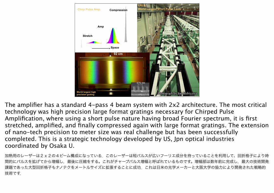
The amplifier has a standard 4-pass 4 beam system with 2x2 architecture. The most critical technology was high precision large format gratings necessary for Chirped Pulse Amplification, where using a short pulse nature having broad Fourier spectrum, it is first stretched, amplified, and finally compressed again with large format gratings. The extension of nano-tech precision to meter size was real challenge but has been successfully completed. This is a strategic technology developed by US, Jpn optical industries coordinated by Osaka U.加熱用のレーザーは2x2の4ビーム構成になっている.このレーザーは短パルスが広いフーリエ成分を持っていることを利用して、回折格子により時間的にパルスを拡げてから増幅し,最後に圧縮をする。これがチャープパルス増幅と呼ばれているものです。増幅部は数年前に完成し,最大の技術開発課題であった大型回折格子もナノテクをメートルサイズに拡張することに成功.これは日米の光学メーカーと大阪大学の協力により開発された戦略的技術です.
ILE OSAKA
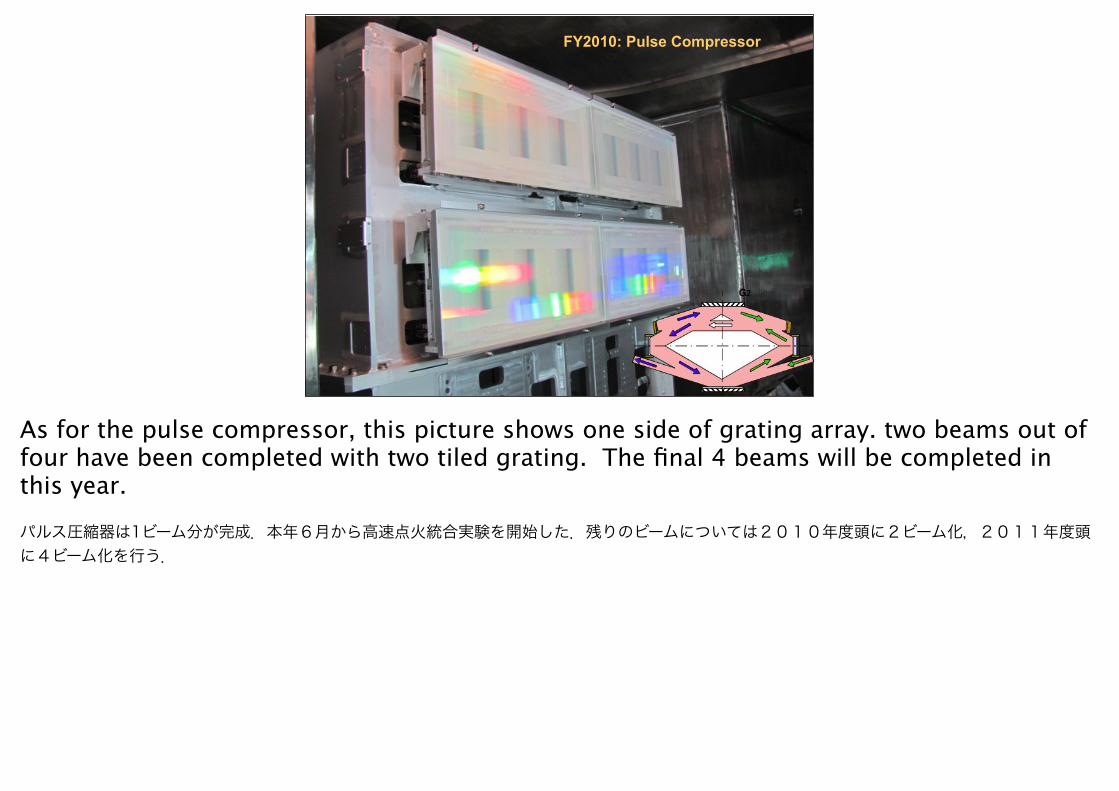
FY2010: Pulse Compressor
5
As for the pulse compressor, this picture shows one side of grating array. two beams out of four have been completed with two tiled grating. The final 4 beams will be completed in this year.
パルス圧縮器は1ビーム分が完成.本年6月から高速点火統合実験を開始した.残りのビームについては2010年度頭に2ビーム化,2011年度頭に4ビーム化を行う.
ILE OSAKA
13
500 um
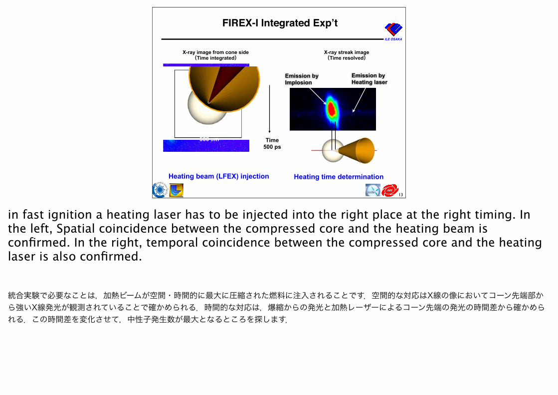
FIREX-I Integrated Expʼt
Time500 ps
Heating beam (LFEX) injection Heating time determination
X-ray image from cone side(Time integrated)
X-ray streak image(Time resolved)
Emission byImplosion
Emission byHeating laser
in fast ignition a heating laser has to be injected into the right place at the right timing. In the left, Spatial coincidence between the compressed core and the heating beam is confirmed. In the right, temporal coincidence between the compressed core and the heating laser is also confirmed.
統合実験で必要なことは,加熱ビームが空間・時間的に最大に圧縮された燃料に注入されることです.空間的な対応はX線の像においてコーン先端部から強いX線発光が観測されていることで確かめられる.時間的な対応は,爆縮からの発光と加熱レーザーによるコーン先端の発光の時間差から確かめられる.この時間差を変化させて,中性子発生数が最大となるところを探します.
ILE OSAKA
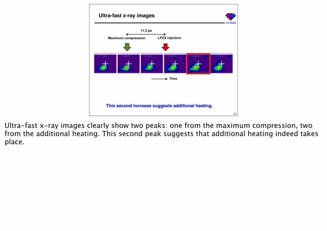
Ultra-fast x-ray images
Maximum compression LFEX injection
This second increase suggests additional heating.
Time
t=0 ps 10.5 ps 21.0 ps 31.5 ps 42.0 ps 52.5 ps
11.5 ps
14
Ultra-fast x-ray images clearly show two peaks: one from the maximum compression, two from the additional heating. This second peak suggests that additional heating indeed takes place.
ILE OSAKA
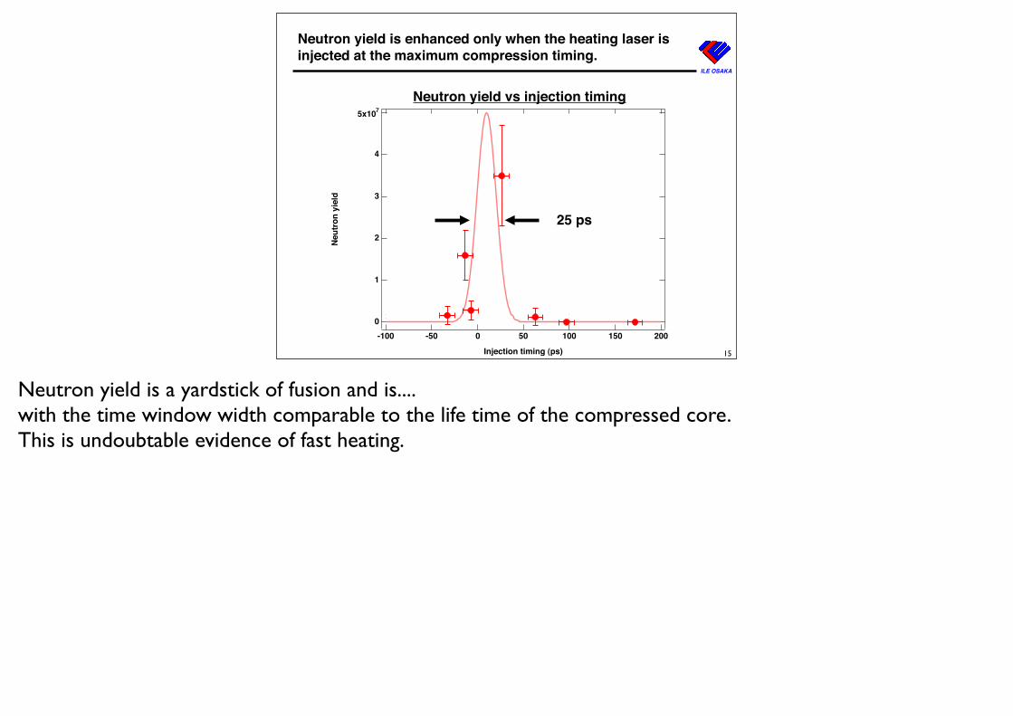
Neutron yield is enhanced only when the heating laser is injected at the maximum compression timing.
Neutron yield vs injection timing
25 ps
15
5x10⁷
4
3
2
1
0N
eutr
on y
ield
200150100500-50-100
Injection timing (ps)
Neutron yield is a yardstick of fusion and is....with the time window width comparable to the life time of the compressed core.This is undoubtable evidence of fast heating.
ILE OSAKA
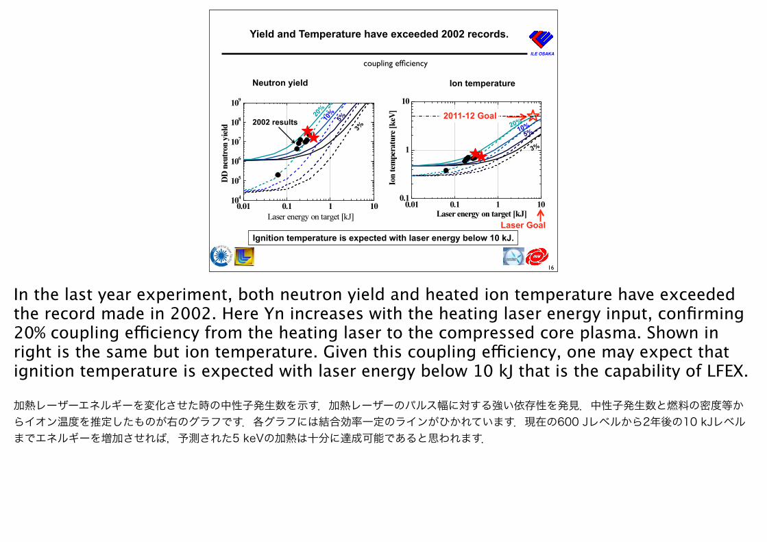
Yield and Temperature have exceeded 2002 records.
Neutron yield Ion temperature
coupling efficiency
Ignition temperature is expected with laser energy below 10 kJ.
2002 results
16
20%
10%
5%
3% 20%10%5%
3%
2011-12 Goal
Laser Goal
In the last year experiment, both neutron yield and heated ion temperature have exceeded the record made in 2002. Here Yn increases with the heating laser energy input, confirming 20% coupling efficiency from the heating laser to the compressed core plasma. Shown in right is the same but ion temperature. Given this coupling efficiency, one may expect that ignition temperature is expected with laser energy below 10 kJ that is the capability of LFEX.
加熱レーザーエネルギーを変化させた時の中性子発生数を示す.加熱レーザーのパルス幅に対する強い依存性を発見.中性子発生数と燃料の密度等からイオン温度を推定したものが右のグラフです.各グラフには結合効率一定のラインがひかれています.現在の600 Jレベルから2年後の10 kJレベルまでエネルギーを増加させれば,予測された5 keVの加熱は十分に達成可能であると思われます.
ILE OSAKA
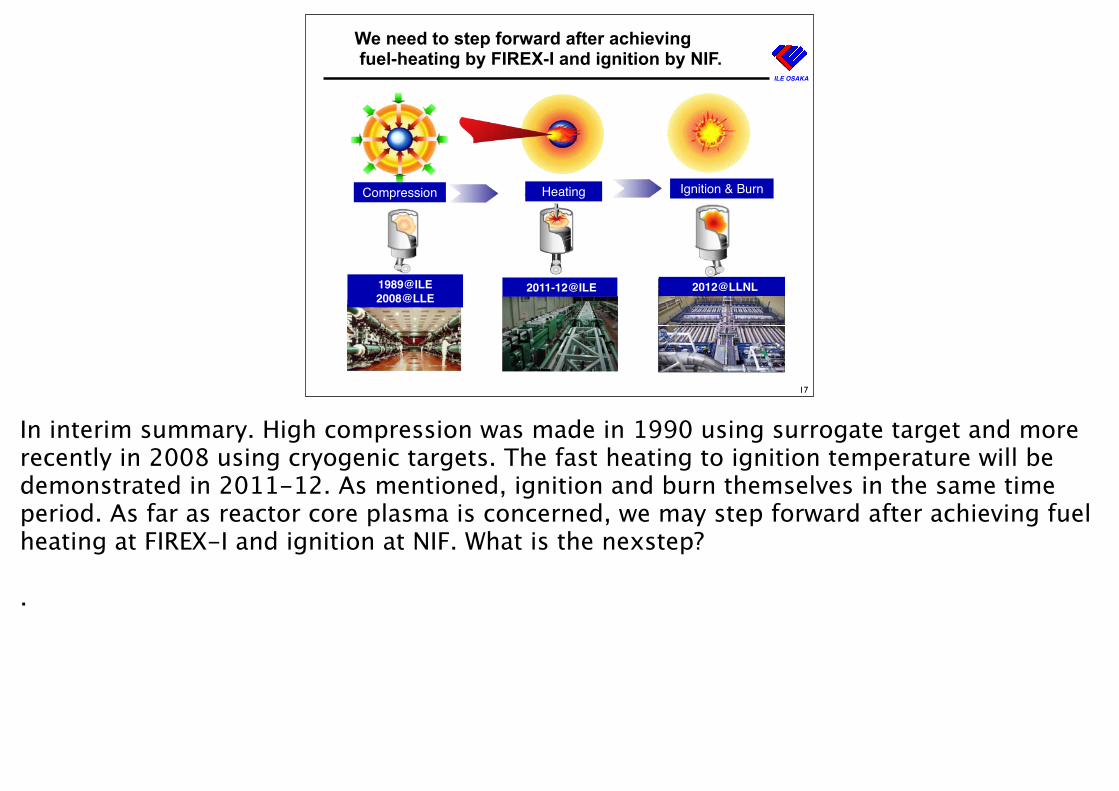
We need to step forward after achieving fuel-heating by FIREX-I and ignition by NIF.
2011-12@ILE1989@ILE 2008@LLE
Compression Heating Ignition & Burn
Laser bayLaser bay
NIF-0709-16940 Rotary of Rossmoor 31
2012@LLNL
17
In interim summary. High compression was made in 1990 using surrogate target and more recently in 2008 using cryogenic targets. The fast heating to ignition temperature will be demonstrated in 2011-12. As mentioned, ignition and burn themselves in the same time period. As far as reactor core plasma is concerned, we may step forward after achieving fuel heating at FIREX-I and ignition at NIF. What is the nexstep?
.
ILE OSAKA
12
Implosion Laser100 kJ x1Hz =100 kW
Reaction chamber10 MWth
Heating Laser 100 kJx1Hz = 100 kW
Pellet Injector
Power Generator 4 MWe
Laboratory Inertial Fusion Test (i-)LIFT
IFE ForumTomabechi Committee (i-)LIFT can generate net electricity.
A landmark of fusion energy development
This is again Laboratory Inertial Fusion Test. But now we access in more detail. Two-story laser: one for implosion the other for heating. Each has 100 kJ (twenty times smaller than NIF) but has 1Hz rep rate. With this energy level, we may expect a target gain of 50, generating 10 MWth. With standand electrical conversion efficiency 40%, 4 MWe is generated. Half of the electricity is recycled to the laser. So one of the important requirement for reactor lasers is 10% laser efficiency at 1 Hz reprate. Can we make it?
ILE OSAKA
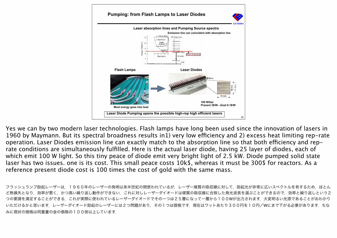
Pumping: from Flash Lamps to Laser Diodes
80万円→数万円
Laser absorption lines and Pumping Source spectra
Flash Lamps Laser Diodes
Laser Diode Pumping opens the possible high-rep high efficient lasers
Most energy goes into heat
Emission line can coincident with absorption line
100 W/bar Present 3$/W→Goal 0.1$/W
19
Yes we can by two modern laser technologies. Flash lamps have long been used since the innovation of lasers in 1960 by Maymann. But its spectral broadness results in1) very low efficiency and 2) excess heat limiting rep-rate operation. Laser Diodes emission line can exactly match to the absorption line so that both efficiency and rep-rate conditions are simultaneously fulfilled. Here is the actual laser diode, having 25 layer of diodes, each of which emit 100 W light. So this tiny peace of diode emit very bright light of 2.5 kW. Diode pumped solid state laser has two issues. one is its cost. This small peace costs 10k$, whereas it must be 300$ for reactors. As a reference present diode cost is 100 times the cost of gold with the same mass.
フラッシュランプ励起レーザーは,1960年のレーザーの発明以来半世紀の間使われているが,レーザー媒質の吸収線に対して,励起光が非常に広いスペクトルを有するため,ほとんど熱損失となり,効率が悪く,かつ高い繰り返し動作ができない.これに対しレーザーダイオードは媒質の吸収線に合致した発光波長を選ぶことができるので,効率と繰り返しという2つの要請を満足することができる.これが実際に使われているレーザーダイオードでその一つは25層になって一層から100Wが出力されます.大変明るい光源であることがおわかりいただけるかと思います.レーザーダイオード励起のレーザーには2つ問題があり,その1つは価格です.現在はワットあたり300円を10円/Wにまで下がる必要があります.ちなみに現状の価格は同重量の金の価格の100倍以上しています.
ILE OSAKA
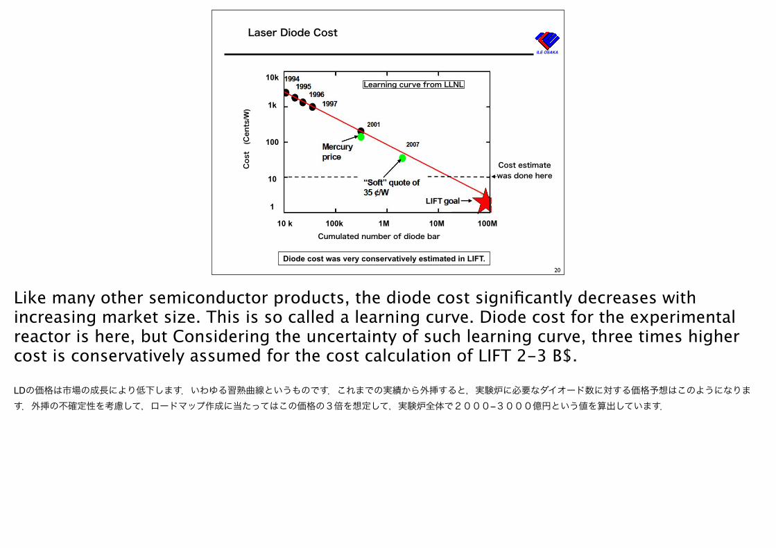
Laser Diode Cost
10k
1k
100
10
1
10 k 100k 1M 10M 100M
Cost
(Cents
/W)
Cumulated number of diode bar
Cost estimatewas done here
Learning curve from LLNL
Diode cost was very conservatively estimated in LIFT.
LIFT
20
Like many other semiconductor products, the diode cost significantly decreases with increasing market size. This is so called a learning curve. Diode cost for the experimental reactor is here, but Considering the uncertainty of such learning curve, three times higher cost is conservatively assumed for the cost calculation of LIFT 2-3 B$.
LDの価格は市場の成長により低下します.いわゆる習熟曲線というものです.これまでの実績から外挿すると,実験炉に必要なダイオード数に対する価格予想はこのようになります.外挿の不確定性を考慮して,ロードマップ作成に当たってはこの価格の3倍を想定して,実験炉全体で2000−3000億円という値を算出しています.
ILE OSAKA
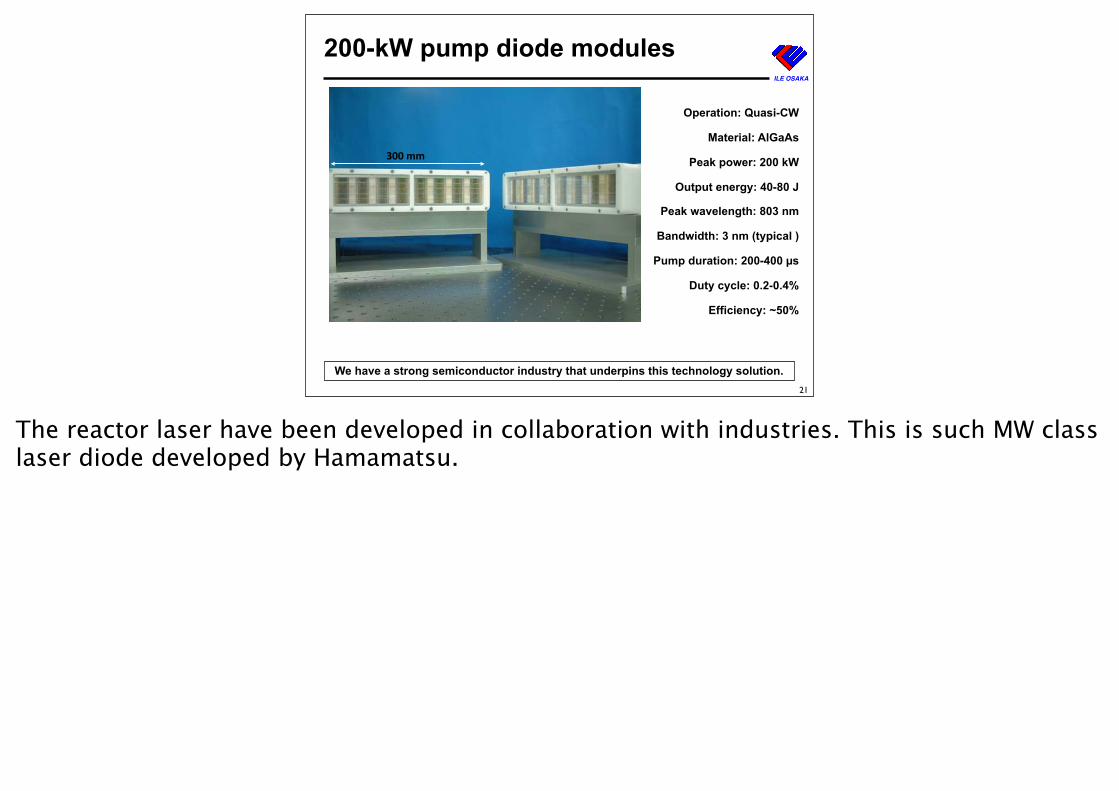
200-kW pump diode modules
300 mm
Operation: Quasi-CW
Material: AlGaAs
Peak power: 200 kW
Output energy: 40-80 J
Peak wavelength: 803 nm
Bandwidth: 3 nm (typical )
Pump duration: 200-400 µs
Duty cycle: 0.2-0.4%
Efficiency: ~50%
We have a strong semiconductor industry that underpins this technology solution.21
The reactor laser have been developed in collaboration with industries. This is such MW class laser diode developed by Hamamatsu.
ILE OSAKA
13
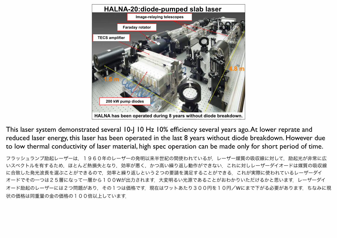
Image-relaying telescopes
200 kW pump diodes
4.8 m1.5 m
TECS amplifier
Faraday rotator
HALNA-20:diode-pumped slab laser
HALNA has been operated during 8 years without diode breakdown.
This laser system demonstrated several 10-J 10 Hz 10% efficiency several years ago. At lower reprate and reduced laser energy, this laser has been operated in the last 8 years without diode breakdown. However due to low thermal conductivity of laser material, high spec operation can be made only for short period of time.
フラッシュランプ励起レーザーは,1960年のレーザーの発明以来半世紀の間使われているが,レーザー媒質の吸収線に対して,励起光が非常に広いスペクトルを有するため,ほとんど熱損失となり,効率が悪く,かつ高い繰り返し動作ができない.これに対しレーザーダイオードは媒質の吸収線に合致した発光波長を選ぶことができるので,効率と繰り返しという2つの要請を満足することができる.これが実際に使われているレーザーダイオードでその一つは25層になって一層から100Wが出力されます.大変明るい光源であることがおわかりいただけるかと思います.レーザーダイオード励起のレーザーには2つ問題があり,その1つは価格です.現在はワットあたり300円を10円/Wにまで下がる必要があります.ちなみに現状の価格は同重量の金の価格の100倍以上しています.
ILE OSAKA
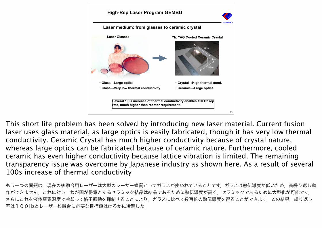
High-Rep Laser Program GEMBU
18mm
60mm
60mm
Laser Glasses Yb: YAG Cooled Ceramic Crystal
Several 100s increase of thermal conductivity enables 100 Hz rep rate, much higher than reactor requirement.
・Glass→Large optics・Glass→Very low thermal conductivity
・Crystal→High thermal cond.・Ceramic→Large optics
Laser medium: from glasses to ceramic crystal
23
This short life problem has been solved by introducing new laser material. Current fusion laser uses glass material, as large optics is easily fabricated, though it has very low thermal conductivity. Ceramic Crystal has much higher conductivity because of crystal nature, whereas large optics can be fabricated because of ceramic nature. Furthermore, cooled ceramic has even higher conductivity because lattice vibration is limited. The remaining transparency issue was overcome by Japanese industry as shown here. As a result of several 100s increase of thermal conductivity
もう一つの問題は,現在の核融合用レーザーは大型のレーザー媒質としてガラスが使われていることです.ガラスは熱伝導度が低いため,高繰り返し動作ができません.これに対し,わが国が得意とするセラミック結晶は結晶であるために熱伝導度が高く,セラミックであるために大型化が可能です.さらにこれを液体窒素温度で冷却して格子振動を抑制することにより,ガラスに比べて数百倍の熱伝導度を得ることができます.この結果,繰り返し率は100Hzとレーザー核融合に必要な目標値ははるかに凌駕した.
ILE OSAKA
24
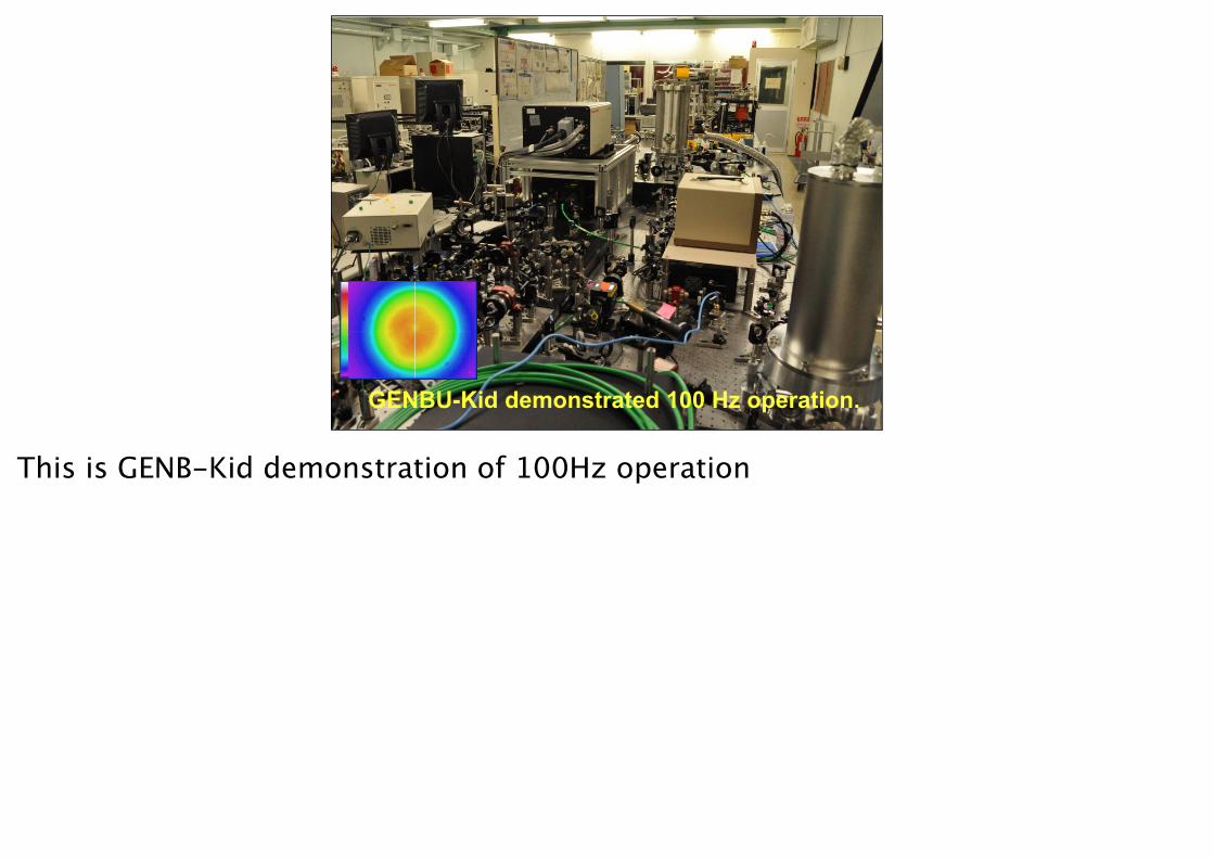
GENBU-Kid demonstrated 100 Hz operation.
This is GENB-Kid demonstration of 100Hz operation
ILE OSAKA
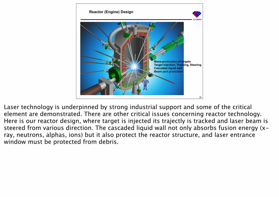
Reactor (Engine) Design
25
Mass-production of targetsTarget injection, Tracking, SteeringCascaded liquid wallBeam port protection
Laser technology is underpinned by strong industrial support and some of the critical element are demonstrated. There are other critical issues concerning reactor technology. Here is our reactor design, where target is injected its trajectly is tracked and laser beam is steered from various direction. The cascaded liquid wall not only absorbs fusion energy (x-ray, neutrons, alphas, ions) but it also protect the reactor structure, and laser entrance window must be protected from debris.
ILE OSAKA
Most Critical Elements of IFE Reactors Have Been Addressed and/or Demonstrated.
26日本のペレット製造技術は米国へ移転され,NIF点火用ターゲットのスペックを満足した.
��������������������
ペレット
Fast IgnitonReactor
大量生産例
日本のペレット製造技術は米国へ移転され,NIF点火用ターゲットのスペックを満足した.
��������������������
ペレット
Fast IgnitonReactor
大量生産例
Mass productionof targets
Target trackingTarget injection
v=30 m/s, 9000 fps (Movie:1/600)
KODAK, EKTAPRO 4540
!6, 0.2g Al (O.D.15x30)
10mm
no-deceleration
deceleration
ペレット
日米共同研究・Air gun方式・1km/s・10Hz
��������� ��������
アルミ製サボーペレット直径3mm
加熱ビーム注入用コーン
日本最高を出した女子エアーライフルの弾痕.
チャンバー中心でのペレット位置精度は100ミクロンが期待できる.
炉用に必要な精度 30-100ミクロンを保証するために・レーザー生成チャネルによる飛行の安定化・光学的全自動ビームステアリングを検討している.
Position measurement of 5 mm diameter target (z’ = 10 m, L = 10 cm)
Xc (
pixe
l)
!d (µm)
Reference value
" = 2.93 µm
Emax = - 8.06 µm
Measured value
Parallel beam
Xc (
pixe
l)
!d (µm)
Xc = 42.484 !d + 665.368
" = 0.06 µm
Emax = - 0.15 µm
Measured value
Diverging beam1-µm precision demonstrated
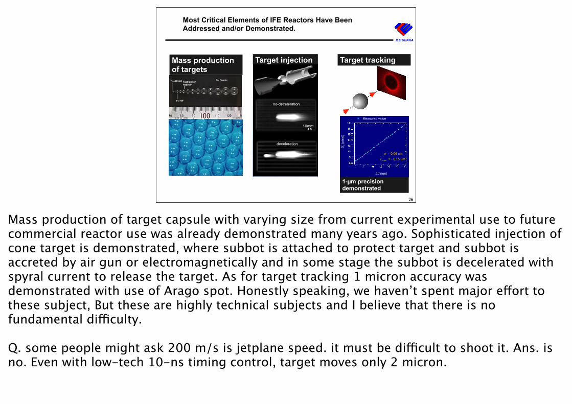
Mass production of target capsule with varying size from current experimental use to future commercial reactor use was already demonstrated many years ago. Sophisticated injection of cone target is demonstrated, where subbot is attached to protect target and subbot is accreted by air gun or electromagnetically and in some stage the subbot is decelerated with spyral current to release the target. As for target tracking 1 micron accuracy was demonstrated with use of Arago spot. Honestly speaking, we haven’t spent major effort to these subject, But these are highly technical subjects and I believe that there is no fundamental difficulty.
Q. some people might ask 200 m/s is jetplane speed. it must be difficult to shoot it. Ans. is no. Even with low-tech 10-ns timing control, target moves only 2 micron.
ILE OSAKA
Most Critical Elements of IFE Reactors Have Been Addressed and/or Demonstrated.
27
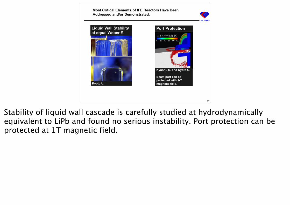
Liquid Wall Stability at equal Weber #
Kyoto U.
Port Protection
Kyushu U. and Kyoto U.
Beam port can be protected with 1-T magnetic field.
Stability of liquid wall cascade is carefully studied at hydrodynamically equivalent to LiPb and found no serious instability. Port protection can be protected at 1T magnetic field.
Alliance
28
with
International IFEMagnetic fusion/Reactor designIndustries
Although there are so many important areas where R&D is required, not many people do. We need cooperation and collaboration with international IFE community, magnetic fusion and industries.
ILE OSAKA
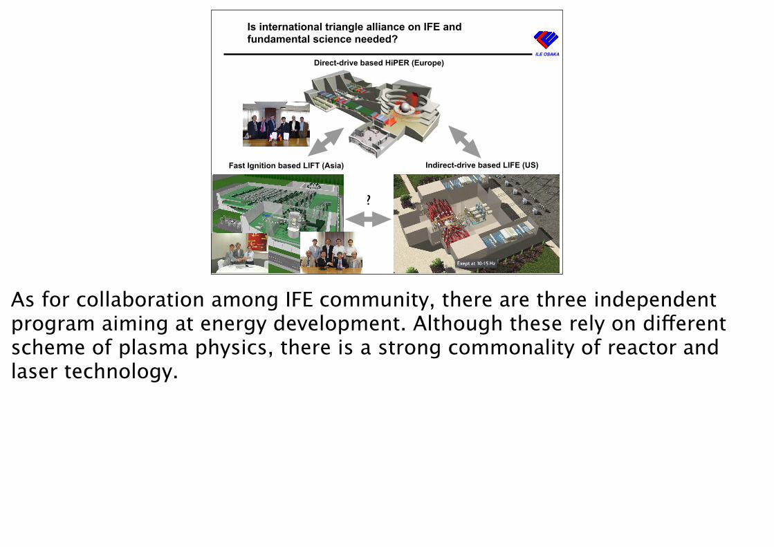
Is international triangle alliance on IFE and fundamental science needed?
29
?
Fast Ignition based LIFT (Asia) Indirect-drive based LIFE (US)
Direct-drive based HiPER (Europe)
As for collaboration among IFE community, there are three independent program aiming at energy development. Although these rely on different scheme of plasma physics, there is a strong commonality of reactor and laser technology.
ILE OSAKA
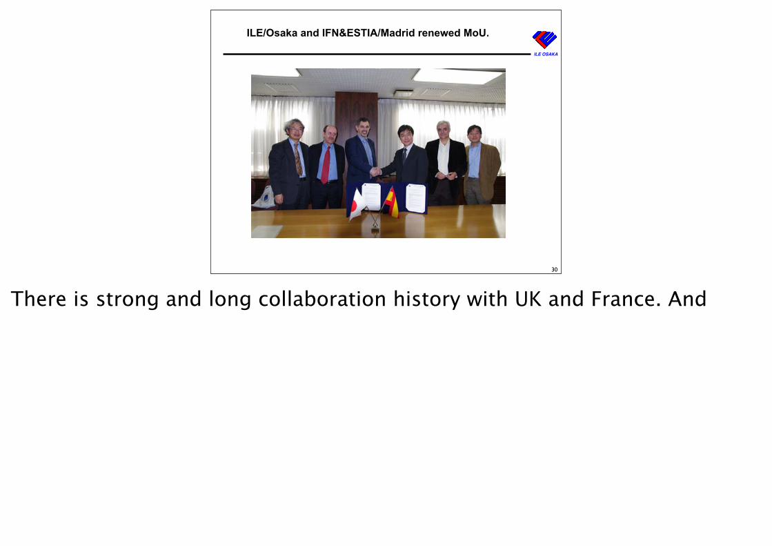
ILE/Osaka and IFN&ESTIA/Madrid renewed MoU.
30
There is strong and long collaboration history with UK and France. And
ILE OSAKA
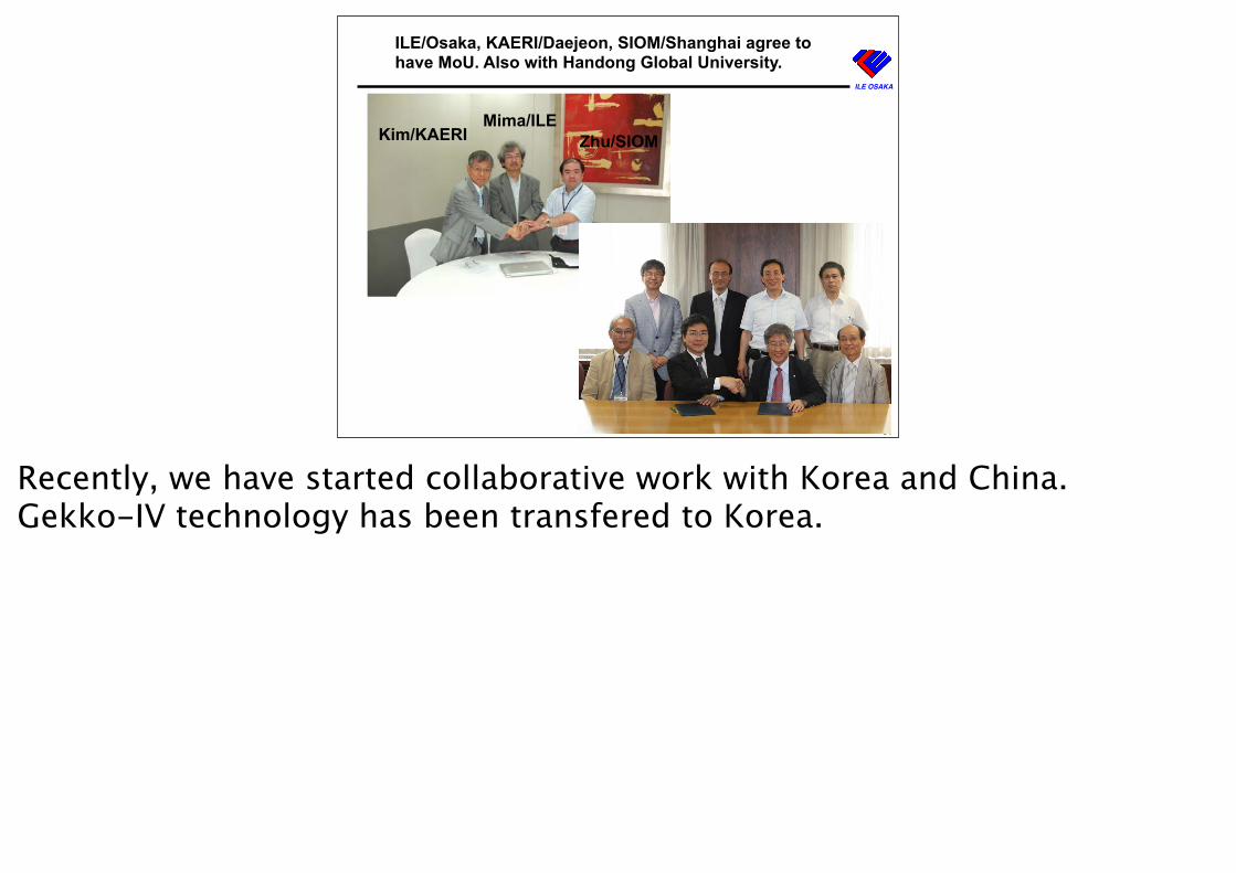
ILE/Osaka, KAERI/Daejeon, SIOM/Shanghai agree to have MoU. Also with Handong Global University.
31
Kim/KAERI Zhu/SIOMMima/ILE
Recently, we have started collaborative work with Korea and China. Gekko-IV technology has been transfered to Korea.
ILE OSAKA
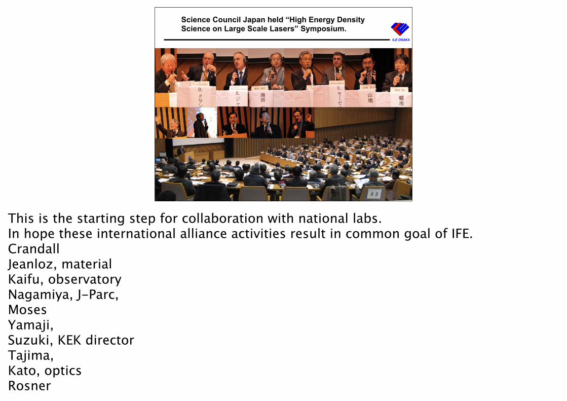
Science Council Japan held “High Energy Density Science on Large Scale Lasers” Symposium.
32
This is the starting step for collaboration with national labs.In hope these international alliance activities result in common goal of IFE.CrandallJeanloz, materialKaifu, observatoryNagamiya, J-Parc,MosesYamaji, Suzuki, KEK directorTajima,Kato, opticsRosner
ILE OSAKA
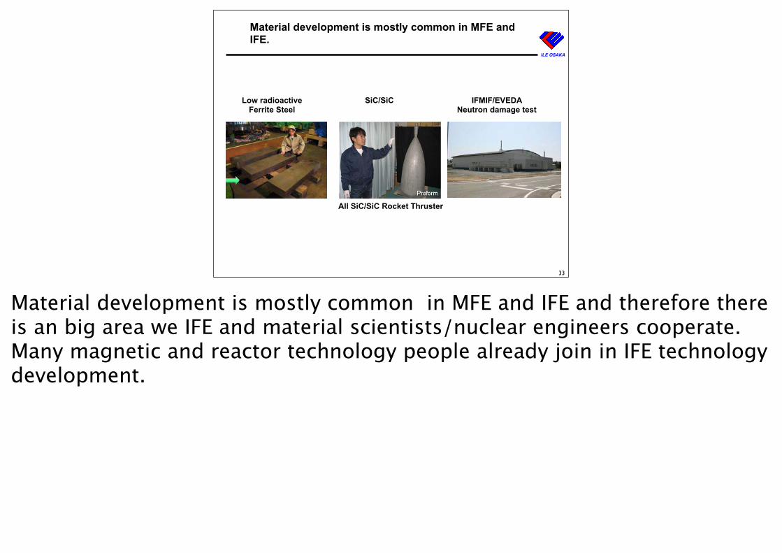
Material development is mostly common in MFE and IFE.
33
特定の原型炉型に依存せず、”Generic”な項目を実施すべしとの共通理解に基づき、ブランケット関連材料開発を主とする、次の5つ項目を選定:
国際核融合エネルギーセンター(IFERC)事業の概況(2)
原型炉工学 研究開発(R&D)
6
a)原型炉ブランケット用材料工学(低放射化フェライト鋼):製造技術、接合技術、照射効果の予測
b)SiCf/SiC 複合材: 機械的特性の評価法の確立、物理特性の評価、照射効果の予測
c)原型炉ブランケット用先進中性子増倍材: ベリライドの製造技術
d)原型炉ブランケット用先進増殖材: 大量製造技術、再処理技術
e)トリチウム技術: 連続運転に対応するモニターの開発、各種材料におけるトリチウム挙動
低放射化フェライト鋼(F82H)の5t溶解を実施
Low radioactiveFerrite Steel
SiC/SiC IFMIF/EVEDA Neutron damage test
All SiC/SiC Rocket Thruster
Material development is mostly common in MFE and IFE and therefore there is an big area we IFE and material scientists/nuclear engineers cooperate. Many magnetic and reactor technology people already join in IFE technology development.
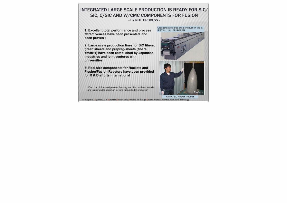
1: Excellent total performance and process attractiveness have been presented and been proven ; 2: Large scale production lines for SiC fibers, green sheets and prepreg-sheets (fibers+matrix) have been established by Japanese Industries and joint ventures with universities.
3: Real size components for Rockets and Fission/Fusion Reactors have been provided for R & D efforts international
INTEGRATED LARGE SCALE PRODUCTION IS READY FOR SIC/SIC, C/SIC AND W/CMC COMPONENTS FOR FUSION
- BY NITE PROCESS -
A. Kohyama: Organization of Advanced Sustainability Initiative for Energy System/ Material, Muroran Institute of Technology
Greensheet/Prepreg-sheet Production line in IEST Co., Ltd., MURORAN
All SiC/SiC Rocket Thruster
10cm dia., 1.8m sized preform foaming machine has been installed and is now under operation for long tube/cylinder production
ILE OSAKA
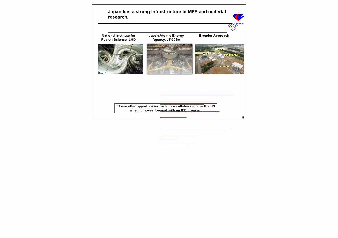
Japan has a strong infrastructure in MFE and material research.
35
ILE OSAKA
Major national labs have started cooperative programs of FIREX-I and HEDP
27
2007/04/21 10:05 PMSubaru Telescope, NAOJ
ページ 1/2http://subarutelescope.org/index.html
[March 30, 2007 Update]
Subaru Captures BeautifulDetails in the Crab Nebula
A new image of the Crab Nebulasupernova remnant taken using thePrime Focus Camera (Suprime-Cam) on the Subaru telescopehighlights the beauty of stellardebris expanding away from thesite of this ancient blast. The high-resolution image captures details ofan elongated tendril of ...
The Subaru Prime Focus Camera Captures Beautiful Details in the CrabNebula - March 12, 2007
Unusual Streak of Ionized Gas Hints at Galaxy's Past - March 5, 2007
Double sun sunset no longer science fiction - February 13, 2007
DARK MATTER MAP REVEALS COSMIC WEB - January 7, 2007
Subaru Telescope Improves its Eyesight by a Factor of Ten - November 20,2006
Star Ends Infancy Abruptly - October 23, 2006
International Workshop of Cosmic Ray Astronomy was Held at Subaru -March 30, 2007
Call for Proposals: Semester S07B - February 13, 2006
Subaru Staff -15- - February 9, 2006
Realuminizing Subaru's Primary Mirror - December 31, 2006
Subaru Reopens to Visitors - November 8, 2006
Japan Atomic Energy Agency, Kansai
National Astronomical Observatory
FIREX-I
A. IwamotoT. MitoH. SakagamiT. OzakiM. Isobe
PoC: T. Norimatsu
Beam Generation
T. TajimaT. KimuraH. DaidoT. KawachiH. Kiriyama
PoC: H. Nishimura
Astrophysics
E. KokuboK. Tomisaka 4 Oversee Organizationsmany others
PoC: H. Takabe
National Institute for Fusion Science
National Institute forFusion Science, LHD
Japan Atomic EnergyAgency, JT-60SA
Broader Approach
These offer opportunities for future collaboration for the US when it moves forward with an IFE program.
ILE OSAKA
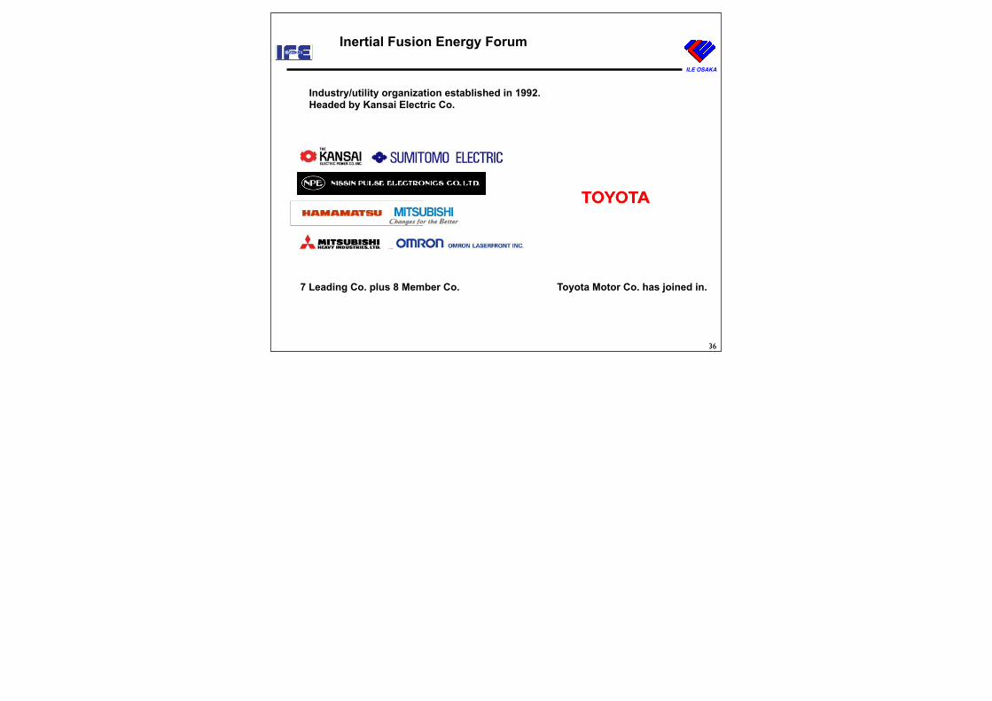
Inertial Fusion Energy Forum
36
Industry/utility organization established in 1992.Headed by Kansai Electric Co.
7 Leading Co. plus 8 Member Co. Toyota Motor Co. has joined in.
ILE OSAKA
19
Implosion Laser
100 kJ x1Hz =100 kW
Reaction chamber
10 MWth
Heating Laser
100 kJx1Hz = 100 kW
Pellet Injector
Power Generator 4 MWe
IFEForum
Committee of Inertial Fusion Energy
Development
International Laboratory Inertial Fusion Test
ILE OSAKA
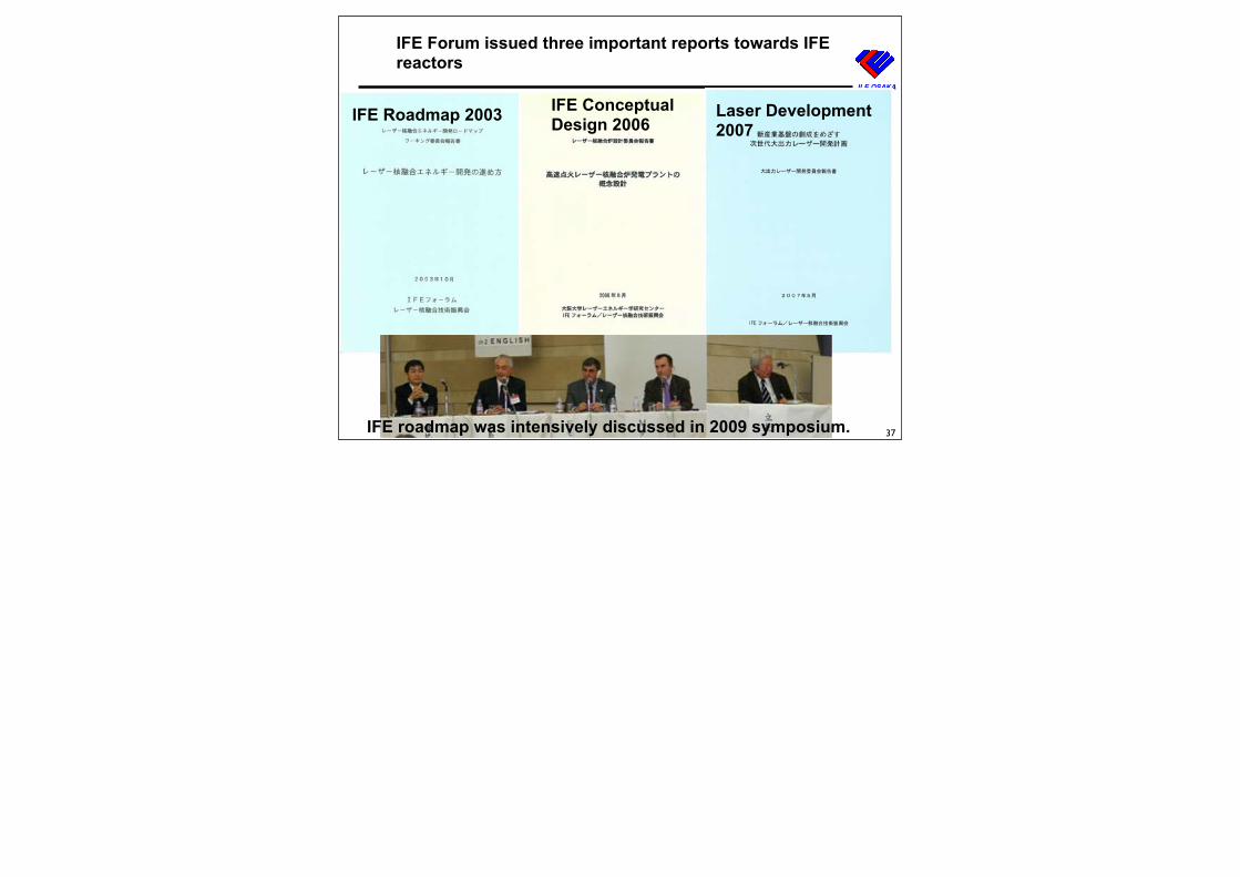
IFE Forum issued three important reports towards IFE reactors
37
IFE Roadmap 2003 IFE Conceptual Design 2006
Laser Development2007
IFE roadmap was intensively discussed in 2009 symposium.
低価格電力供給 3.5yen/kWhLaser diodes & DPSSL technology
持続可能なエネルギーClean energy, Zero emission
光産業の創成Fusion physics, Nuclear science
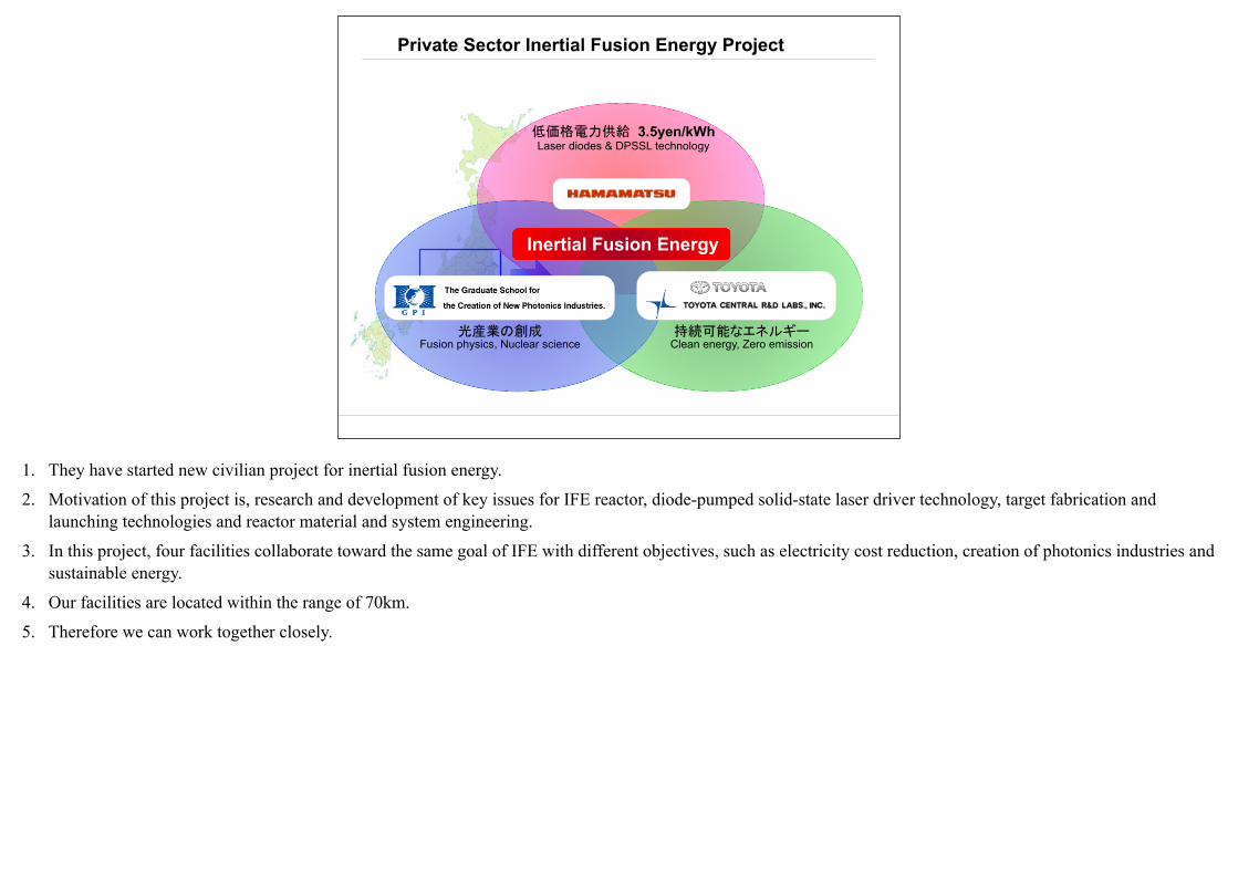
Private Sector Inertial Fusion Energy Project
Inertial Fusion Energy
1. They have started new civilian project for inertial fusion energy.
2. Motivation of this project is, research and development of key issues for IFE reactor, diode-pumped solid-state laser driver technology, target fabrication and launching technologies and reactor material and system engineering.
3. In this project, four facilities collaborate toward the same goal of IFE with different objectives, such as electricity cost reduction, creation of photonics industries and sustainable energy.
4. Our facilities are located within the range of 70km.
5. Therefore we can work together closely.
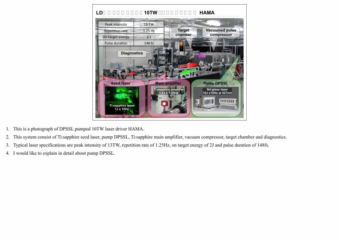
LD励起レーザーによる10TW ドライバーレーザー HAMA
Target chamber
Vacuumed pulse compressor
Diagnostics
Peak intensity 13 TW
Repe11on rate 1.25 Hz
On target energy 2 J
Pulse dura1on 148 fs
Seed laser
Ti:sapphire laser1J x 10Hz
Main amplifierTi:sapphire amplifier
3.8J x 1.25Hz
Pump DPSSLNd:glass laser
10J x10Hz at 527nm
1. This is a photograph of DPSSL pumped 10TW laser driver HAMA.
2. This system consist of Ti:sapphire seed laser, pump DPSSL, Ti:sapphire main amplifier, vacuum compressor, target chamber and diagnostics.
3. Typical laser specifications are peak intensity of 13TW, repetition rate of 1.25Hz, on target energy of 2J and pulse duration of 148fs.
4. I would like to explain in detail about pump DPSSL.
ILE OSAKA
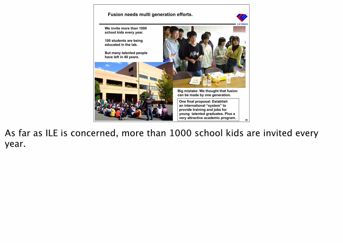
Fusion needs multi generation efforts.
40
We invite more than 1000 school kids every year.
100 students are being educated in the lab.
But many talented people have left in 40 years.
One final proposal: Establishan international “system” to provide training and jobs for young talented graduates. Plus a very attractive academic program.
Big mistake: We thought that fusion can be made by one generation.
As far as ILE is concerned, more than 1000 school kids are invited every year.
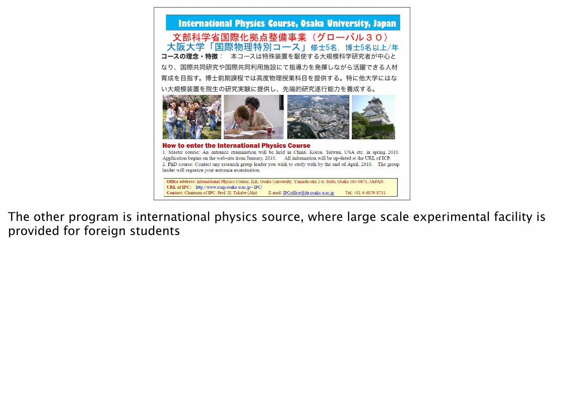
文部科学省国際化拠点整備事業(グローバル30)大阪大学「国際物理特別コース」修士5名,博士5名以上/年コースの理念・特徴: 本コースは特殊装置を駆使する大規模科学研究者が中心となり、国際共同研究や国際共同利用施設にて指導力を発揮しながら活躍できる人材育成を目指す。博士前期課程では高度物理授業科目を提供する。特に他大学にはない大規模装置を院生の研究実験に提供し、先端的研究遂行能力を養成する。
The other program is international physics source, where large scale experimental facility is provided for foreign students
ILE OSAKA
30
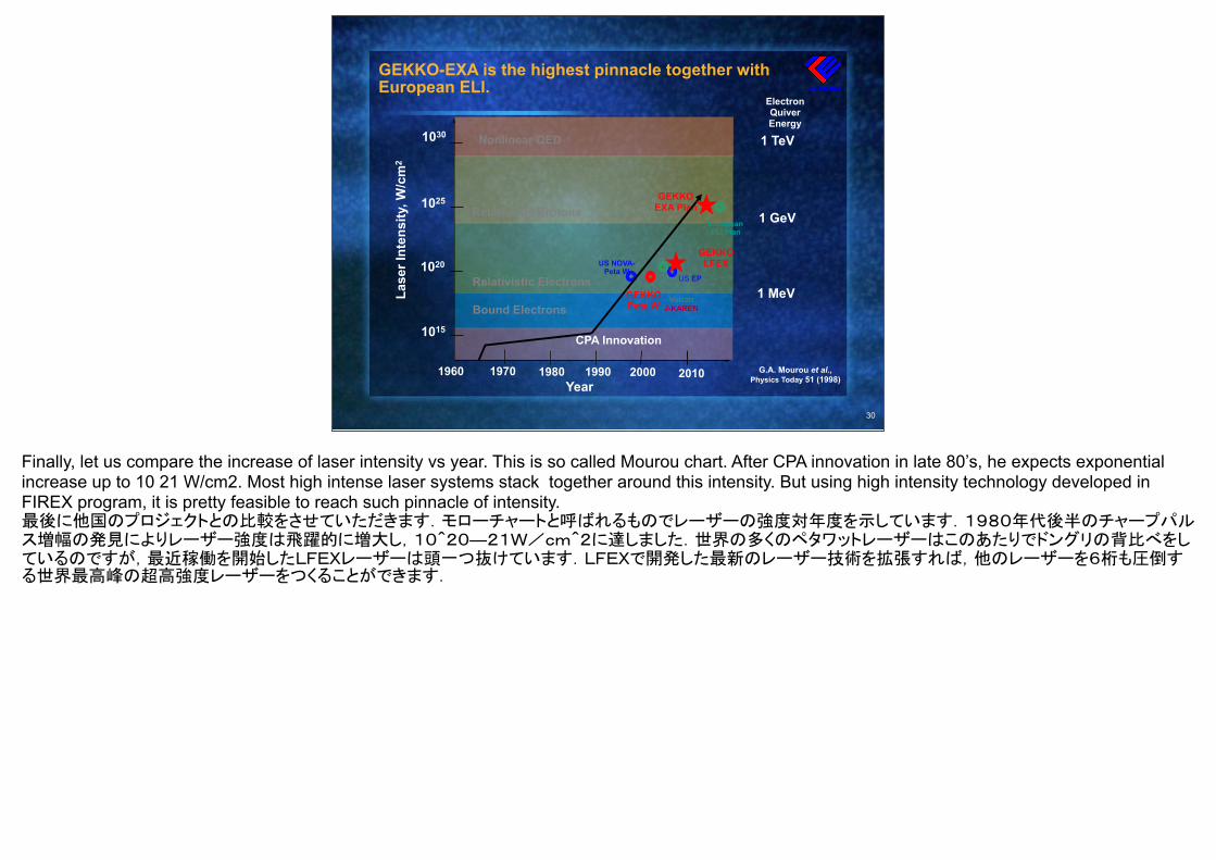
GEKKO-EXA is the highest pinnacle together withEuropean ELI.
G.A. Mourou et al., Physics Today 51 (1998)
1 MeV
1 GeV
1 TeV
Year 2010 200019901980 19701960
1015
1020
1025
1030
Lase
r Int
ensi
ty, W
/cm
2
Relativistic Electrons
Nonlinear QED
Bound Electrons
Relativistic Protons
US EP
US NOVA-Peta W
European ELI Plan
GEKKOEXA Plan
GEKKOLFEX
GEKKOPeta W
ElectronQuiver Energy
CPA Innovation
Finally, let us compare the increase of laser intensity vs year. This is so called Mourou chart. After CPA innovation in late 80’s, he expects exponential increase up to 10 21 W/cm2. Most high intense laser systems stack together around this intensity. But using high intensity technology developed in FIREX program, it is pretty feasible to reach such pinnacle of intensity.最後に他国のプロジェクトとの比較をさせていただきます.モローチャートと呼ばれるものでレーザーの強度対年度を示しています.1980年代後半のチャープパルス増幅の発見によりレーザー強度は飛躍的に増大し,10^20—21W/cm^2に達しました.世界の多くのペタワットレーザーはこのあたりでドングリの背比べをしているのですが,最近稼働を開始したLFEXレーザーは頭一つ抜けています.LFEXで開発した最新のレーザー技術を拡張すれば,他のレーザーを6桁も圧倒する世界最高峰の超高強度レーザーをつくることができます.
ILE OSAKA
Summary
•After 50 years from the innovation of lasers, it is an eve of the first controlled fusion burn in humankind.
•Compactness of fast ignition will accelerate inertial fusion energy development. This option will soon be tested in FIREX program.
• IFE physic and engineering programs would converge onto an experimental reactor, such as LIFE and LIFT, that will lift up people’s spirits.
•Most of critical elements of IFE reactors have been addressed and/or demonstrated.
43