Embed Size (px)
Citation preview
Full Terms & Conditions of access and use can be found athttp://www.tandfonline.com/action/journalInformation?journalCode=tctm20
Download by: [West Virginia University Libraries] Date: 07 December 2017, At: 11:09
Combustion Theory and Modelling
ISSN: 1364-7830 (Print) 1741-3559 (Online) Journal homepage: http://www.tandfonline.com/loi/tctm20
Influence of gas compressibility on a burningaccident in a mining passage
Sinan Demir, Anish Raman Calavay & V'yacheslav Akkerman
To cite this article: Sinan Demir, Anish Raman Calavay & V'yacheslav Akkerman (2017): Influenceof gas compressibility on a burning accident in a mining passage, Combustion Theory andModelling, DOI: 10.1080/13647830.2017.1403654
To link to this article: https://doi.org/10.1080/13647830.2017.1403654
Published online: 07 Dec 2017.
Submit your article to this journal
View related articles
View Crossmark data

Combustion Theory and Modelling, 2017
https://doi.org/10.1080/13647830.2017.1403654
Influence of gas compressibility on a burning accidentin a mining passage
Sinan Demir, Anish Raman Calavay and V’yacheslav Akkerman∗
Center for Innovation in Gas Research and Utilization (CIGRU), Center for Alternative Fuels,Engines and Emissions (CAFEE), Computational Fluid Dynamics and Applied Multi-PhysicsCenter, Department of Mechanical and Aerospace Engineering, West Virginia University, 395
Evansdale Drive, Morgantown, WV 26506-6106, USA
(Received 22 May 2017; accepted 24 October 2017)
A recent predictive scenario of a methane/air/coal dust fire in a mining passage is ex-tended by incorporating the effect of gas compressibility into the analysis. The compress-ible and incompressible formulations are compared, qualitatively and quantitatively, inboth the two-dimensional planar and cylindrical-axisymmetric geometries, and a de-tailed parametric study accounting for coal-dust combustion is performed. It is shownthat gas compression moderates flame acceleration, and its impact depends on the typeof the fuel, its various thermal-chemical parameters as well as on the geometry of theproblem. While the effect of gas compression is relatively minor for the lean and richflames, providing 5–25% reduction in the burning velocity and thereby justifying theincompressible formulation in that case, such a reduction appears significant, up to 70%for near-stoichiometric methane–air combustion, and therefore it should be incorpo-rated into a rigorous formulation. It is demonstrated that the flame tip velocity remainsnoticeably subsonic in all the cases considered, which is opposite to the prediction of theincompressible formulation, but qualitatively agrees with the experimental predictionsfrom the literature.
Keywords: gaseous–dusty combustion; gas compression; Darrieus–Landau instability;expanding and finger flames; flame acceleration; mining fire safety
1. Introduction
Accidental burning events in a gaseous environment with combustible dust impuritiesconstitute a tremendous hazard for personnel and equipment in industries dealing withflammable gases and explosive materials. This primarily concerns (though is not limitedto) the coalmining industry, which traditionally exhibits ones of the highest occupationalfatality and injury rates, claiming hundreds of lives every year [1]. Specifically, coalminingaccidents are often associated with spontaneous methane explosions in mining passagesdue to unwanted accidental ignitions of the hidden methane pockets during the excavatingprocess. The conventional safety strategies against a mining accident include: (i) preventionof an onset of a flame (deflagration) or a detonation wave; (ii) suppression (or, at least,mitigation) of flame spreading if it is nevertheless sparked; and (iii) (if flame spreadingcannot be terminated) prevention of a deflagration-to-detonation transition (DDT) event.The latter is important because a shock-wise nature of a detonation constitutes a huge
∗Corresponding author. Email: [email protected]
C© 2017 Informa UK Limited, trading as Taylor & Francis Group
Dow
nloa
ded
by [
Wes
t Vir
gini
a U
nive
rsity
Lib
rari
es]
at 1
1:09
07
Dec
embe
r 20
17

2 S. Demir et al.
Figure 1. Consecutive stages of the mining fire scenario: (a) ignition of an expanding flame; (b)formation of a cellular flame structure; (c) finger-flame acceleration; (d) flame propagation driven bywall-friction; and (e) flame spreading through obstacles [6].
disaster in coalmines even more than combustion. All these strategies require a funda-mental understanding of all intermediate stages of the flame evolution in a gaseous–dustycoalmining environment. Unfortunately, in spite of the limited experimental [2], compu-tational [3,4] and theoretical [5] studies, which shed some light on methane/air/coal dustcombustion, there is still much to be done to reduce the level of risks in coalmines andother facilities handling combustible dusts [1].
To provide guidance on how to prevent or, at least, control fire disasters in mines,Demir et al. [6] have developed a predictive quantitative scenario of a methane/air/coaldust accident, as illustrated in Figure 1. As for any premixed flame, its propagation ischaracterised by the unstretched laminar flame velocity SL, such that if a flame frontwas planar, it would propagate with this velocity with respect to the fuel mixture. How-ever, premixed flame fronts are not planar in practice, but strongly corrugated such thatthey consume more fuel per unit time and propagate faster. Further, the presence of coaldust particles may also increase the local (laminar) and the global (corrugated) burningvelocities [7].
The original mining fire scenario [6] includes several conceptually distinctive stages.First, an initially smooth flame front (Figure 1(a)) experiences a cellular Darrieus–Landau(DL) instability that may increase the flame velocity several times, e.g. in a passage ofdiameter 1.5–2 m (Figure 1(b)) [8]. Second, when a flame starts approaching a passagewall, it slows down in the radial direction but accelerates in the axial one, thereby acquiringa “finger-like” shape (Figure 1(c)) [9–11]. Overall, the finger-flame surface area grows veryfast, which promotes the flame velocity by an order of magnitude by the time the flamefront contacts a wall [10]. While, theoretically, this finger-shaped acceleration mechanismis scale-invariant, being equally strong in micro-pipes and mining passages, in practice,the Reynolds-dependent factors such as the combustion instabilities and/or turbulence pro-vide the corrections to the flame acceleration scenario, making it scale-dependent [12].Third, the finger-flame acceleration stops as soon as the flame front contacts a wall. Thenthe flame may further accelerate due to wall friction (Figure 1(d)) [13], and/or in-builtobstacles (Figure 1(e)) [14]. However, while the latter two acceleration mechanisms ap-pear of primary importance for some configurations such as micro-chambers, their role isminor in a mining passage (unless obstacles occupy a noticeable fraction of the passage)[6]. Consequently, finger-flame acceleration is assumed to be the dominant mechanism of
Dow
nloa
ded
by [
Wes
t Vir
gini
a U
nive
rsity
Lib
rari
es]
at 1
1:09
07
Dec
embe
r 20
17

Combustion Theory and Modelling 3
flame spreading in a mining accident, and thereby this was the focus of [6]. Specifically,the DL-induced and “finger” acceleration stages in gaseous and gaseous–dusty environ-ments were combined into a unified analytical formulation. The input parameters for thisformulation included the geometry of a passage, the methane–air equivalence ratio, aswell as the size, concentration and other properties of the inert and combustible dustparticles.
The pilot theory [6] did not account for certain factors occurring in a real mine suchas turbulence, shock waves and spatial/temporal variations of the combustible premixture.Furthermore, crucially, [6] employed the approach of an incompressible flow. Accordingto the theoretical prediction of [6], no detonation occurs for methane combustion in atwo-dimensional (2D) geometry, while in the case of propane, detonation is predicted forfuel-rich flames, with the equivalence ratios φ in the range 1 ≤ φ ≤ 1.2. For cylindricalgeometry, this range varies as 0.9 ≤ φ ≤ 1.2 for methane and 0.8 ≤ φ ≤ 1.3 for propane.Although propane–air combustion is not the case in a coalmine, it was included in [6] andthe present analyses for comparison purposes. A threshold condition for the DDT is thatthe maximal attainable burning velocity should be high enough to generate a sufficientlystrong shock wave, ahead of a flame front, to cause auto-ignition of the compressed re-actants located between the shock and the flame [15]. Experimental studies [16,17] andnumerous computational simulations of DDT [18,19] have shown that even for highlyexplosive mixtures, e.g. hydrogen–oxygen or ethylene–oxygen, an exponential grows ofthe flame tip velocity stopped much earlier than this velocity would reach the soundbarrier.
However, while the incompressible scenario [6] is acceptable for describing the initialstages of burning, gas compression becomes substantial by the end of the “finger” stage(Figure 1(c)), when the velocity of the flame front may start approaching a near-sonicvalue. Gas compression is used to moderate flame acceleration in various configurations[11,14,20]; hence, the same effect is anticipated in the coalmining geometry, and verifyingthis statement constitutes the focus of the present work. Specifically, we quantify therole of gas compressibility in the event of finger flame acceleration in a mining passagewhich may identify the applicability and limitations of the incompressible theory [6].For simplicity, here we deal with 2D-planar and cylindrical-axisymmetric configurations,which are acceptable to relate the incompressible and compressible analyses, while morerealistic 3D geometry will be considered elsewhere. Starting with gaseous combustion, theformulation is then extended to gaseous–dusty flows. The impacts of the equivalence ratioas well as that of the size and concentration of the coal dust particles on the flame evolutionare systematically investigated.
It is shown that gas compression moderates flame acceleration, as expected, and itsimpact depends on various thermal-chemical parameters. While the effect of compressionis relatively minor for lean and rich methane– and propane–air mixtures, thereby justifyingthe incompressible formulation in that case, it appears significant for near-stoichiometriccombustion, and therefore should be incorporated into a rigorous theory. It is shown,accounting for the compressibility effect, that flame propagation actually does not reachthe speed of sound, which conflicts with the incompressible formulation [6], but fits theexperimental findings [16,17] qualitatively.
2. Formulation
We consider an accidental ignition of a methane–air or a propane–air mixture that occursat a distance h from a passage sidewall as illustrated in Figure 1(a). At the early stage of
Dow
nloa
ded
by [
Wes
t Vir
gini
a U
nive
rsity
Lib
rari
es]
at 1
1:09
07
Dec
embe
r 20
17
4 S. Demir et al.
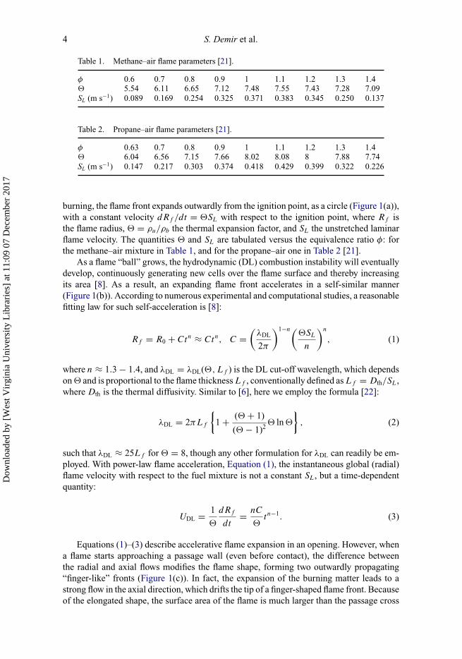
Table 1. Methane–air flame parameters [21].
φ 0.6 0.7 0.8 0.9 1 1.1 1.2 1.3 1.4� 5.54 6.11 6.65 7.12 7.48 7.55 7.43 7.28 7.09SL (m s−1) 0.089 0.169 0.254 0.325 0.371 0.383 0.345 0.250 0.137
Table 2. Propane–air flame parameters [21].
φ 0.63 0.7 0.8 0.9 1 1.1 1.2 1.3 1.4� 6.04 6.56 7.15 7.66 8.02 8.08 8 7.88 7.74SL (m s−1) 0.147 0.217 0.303 0.374 0.418 0.429 0.399 0.322 0.226
burning, the flame front expands outwardly from the ignition point, as a circle (Figure 1(a)),with a constant velocity dRf /dt = �SL with respect to the ignition point, where Rf isthe flame radius, � = ρu/ρb the thermal expansion factor, and SL the unstretched laminarflame velocity. The quantities � and SL are tabulated versus the equivalence ratio φ: forthe methane–air mixture in Table 1, and for the propane–air one in Table 2 [21].
As a flame “ball” grows, the hydrodynamic (DL) combustion instability will eventuallydevelop, continuously generating new cells over the flame surface and thereby increasingits area [8]. As a result, an expanding flame front accelerates in a self-similar manner(Figure 1(b)). According to numerous experimental and computational studies, a reasonablefitting law for such self-acceleration is [8]:
Rf = R0 + Ctn ≈ Ctn, C =(
λDL
2π
)1−n(�SL
n
)n
, (1)
where n ≈ 1.3 − 1.4, and λDL = λDL(�,Lf ) is the DL cut-off wavelength, which dependson � and is proportional to the flame thickness Lf , conventionally defined as Lf = Dth/SL,where Dth is the thermal diffusivity. Similar to [6], here we employ the formula [22]:
λDL = 2πLf
{1 + (� + 1)
(� − 1)2� ln �
}, (2)
such that λDL ≈ 25Lf for � = 8, though any other formulation for λDL can readily be em-ployed. With power-law flame acceleration, Equation (1), the instantaneous global (radial)flame velocity with respect to the fuel mixture is not a constant SL, but a time-dependentquantity:
UDL = 1
�
dRf
dt= nC
�tn−1. (3)
Equations (1)–(3) describe accelerative flame expansion in an opening. However, whena flame starts approaching a passage wall (even before contact), the difference betweenthe radial and axial flows modifies the flame shape, forming two outwardly propagating“finger-like” fronts (Figure 1(c)). In fact, the expansion of the burning matter leads to astrong flow in the axial direction, which drifts the tip of a finger-shaped flame front. Becauseof the elongated shape, the surface area of the flame is much larger than the passage cross
Dow
nloa
ded
by [
Wes
t Vir
gini
a U
nive
rsity
Lib
rari
es]
at 1
1:09
07
Dec
embe
r 20
17
Combustion Theory and Modelling 5
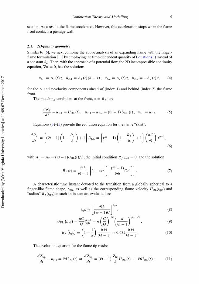
section. As a result, the flame accelerates. However, this acceleration stops when the flamefront contacts a passage wall.
2.1. 2D-planar geometry
Similar to [6], we next combine the above analysis of an expanding flame with the finger-flame formulation [11] by employing the time-dependent quantity of Equation (3) instead ofa constant SL. Then, with the approach of a potential flow, the 2D incompressible continuityequation, ∇u = 0, has the solution:
uz,1 = A1 (t) z, ux,1 = A1 (t) (h − x) , uz,2 = A2 (t) z, ux,2 = −A2 (t) x, (4)
for the z- and x-velocity components ahead of (index 1) and behind (index 2) the flamefront.
The matching conditions at the front, x = Rf , are:
dRf
dt− ux,1 = UDL (t) , ux,1 − ux,2 = (� − 1) UDL (t) , uz,1 = uz,2. (5)
Equations (3)–(5) provide the evolution equation for the flame “skirt”:
dRf
dt=
{(� − 1)
(1 − Rf
h
)+ 1
}UDL =
{(� − 1)
(1 − Rf
h
)+ 1
} (nC
�
)tn−1,
(6)
with A1 = A2 = (� − 1)UDL(t)/h, the initial condition Rf |t=0 = 0, and the solution:
Rf (t) = �h
� − 1
{1 − exp
[− (� − 1)
�hCtn
]}. (7)
A characteristic time instant devoted to the transition from a globally spherical to afinger-like flame shape, tsph, as well as the corresponding flame velocity UDL(tsph) and“radius” Rf (tsph) at such an instant are evaluated as:
tsph ≈[
�h
(� − 1)C
]1/n
, (8)
UDL(tsph
) = nC
�tn−1sph = n
(C
�
)1/n(h
� − 1
)(n−1)/n
, (9)
Rf
(tsph
) =(
1 − 1
e
)h �
(� − 1)≈ 0.632
h �
� − 1. (10)
The evolution equation for the flame tip reads:
dZtip
dt− uz,2 = �UDL (t) ⇒ dZtip
dt= (� − 1)
Ztip
hUDL (t) + �UDL (t) , (11)
Dow
nloa
ded
by [
Wes
t Vir
gini
a U
nive
rsity
Lib
rari
es]
at 1
1:09
07
Dec
embe
r 20
17

6 S. Demir et al.
with the solution:
Ztip (t) = �h
� − 1
{exp
[(� − 1)Ctn
�h
]− 1
}. (12)
Therefore, the flame tip velocity in the laboratory reference frame is:
Utip (t) = dZtip
dt= nCtn−1 exp
[(� − 1)Ctn
�h
]. (13)
The flame skirt contacts the tunnel wall when Rf = h, i.e. at the time instant:
twall ={
h � ln �
(� − 1) C
}1/n
(14)
such that twall/tsph = n√
�. Again, finger-flame acceleration terminates at twall, with theflame tip position, Equation (12), being Ztip(twall) = �h at this instant, and the flame tipvelocity, Equation (13), being Utip(twall) = n�Ctn−1
wall .The analysis above is actually the 2D formulation [6]. We next extend it to account for
small but finite Mach numbers based on the methodology of [11]. However, while a Machnumber associated with flame propagation was constant in [11], namely, Ma = SL/c0 withc0 being the initial sound speed in the fresh mixture, here its counterpart depends on timeas:
Ma (t) = UDL (t)
c0= nC
�
tn−1
c0, (15)
where UDL(t) is given by Equation (3). As soon as the combustion process is substantiallysubsonic, e.g. Ma ≤ 0.3, the flow in the unburnt gas can be treated as isentropic, with theinstantaneous density, pressure and temperature given by [11,23]:
ρu(t)
ρ0=
(1 + γ − 1
2
uz,1(t)
c0
)2/(γ−1)
≈ 1 + Ma(t) (� − 1)
[1 + Ztip(t)
h
], (16)
Pu(t)
P0=
(1 + γ − 1
2
uz,1(t)
c0
)2γ /(γ−1)
≈ 1 + Ma(t) γ (� − 1)
[1 + Ztip(t)
h
], (17)
Tu(t)
T0=
(1 + γ − 1
2
uz,1(t)
c0
)2
≈ 1 + Ma(t) (γ − 1) (� − 1)
[1 + Ztip(t)
h
], (18)
where γ = cp/cv ≈ 1.4 is the adiabatic index and ρ0, P0, T0 the initial density, pressureand temperature in the unburnt gas. Instead of the initial thermal expansion �, we now dealwith an instantaneous (reduced) thermal expansion factor in the form:
ϑ (t) = � − Ma(t) (γ − 1) (� − 1)
[1 + Ztip(t)
h
]. (19)
Dow
nloa
ded
by [
Wes
t Vir
gini
a U
nive
rsity
Lib
rari
es]
at 1
1:09
07
Dec
embe
r 20
17

Combustion Theory and Modelling 7
The 2D continuity equation for small but finite compressibility, ∇u = −(∂Pu/∂t)/γPu,has the solution in the burnt gas:
ux = − (ϑ − 1)UDL (t)
hx, uz =
[− 1
γPu
∂Pu
∂t+ (ϑ − 1)
UDL (t)
h
]z. (20)
Substituting Equations (15)–(20) into a modified Equation (11), Ztip − uz,2[ϑ(t)] =ϑ(t) UDL(t), and further neglecting the 2nd- and higher order terms in Ma, we eventuallyarrive to the evolution equation:
dZtip
dt=
{−n(n − 1)Ctn−2
�c0(� − 1)
(1 + Ztip
h
)
− nCtn−1
�c0
[− (� − 1)nCtn−1
�h
((� − 1)
Ztip
h+ �
)]
+[
1 − (γ − 1) (� − 1)nCtn−1
�c0
(1 + Ztip
h
)]nCtn−1
�h
}Ztip
+[� − (γ − 1) (� − 1)2 nCtn−1
�c0
(1 + Ztip
h
)]nCtn−1
�. (21)
2.2. Cylindrical-axisymmetric geometry
We next briefly recall the incompressible formulation of [6] for the cylindrical geometry.The cylindrical-axisymmetric counterpart of Equation (4) reads:
uz,1 = A1 (t) z, ur,1 = A1 (t)
2
(h2
r− r
), uz,2 = A2 (t) z, ur,2 = −A2 (t)
2r. (22)
The matching conditions at the front, r = Rf , are:
dRf
dt− ur,1 = UDL (t) , ur,1 − ur,2 = (� − 1) UDL (t) , uz,1 = uz,2 (23)
such that A1 = A2 = 2(� − 1)UDL(t)Rf /h2. With the initial condition Rf |t=0 = 0,Equations (3), (22) and (23) provide the evolution equation for the flame “skirt” in theform:
dRf
dt=
{� − (� − 1)
R2f
h2
}UDL (t) =
{� − (� − 1)
R2f
h2
}Sn
L
(2π�
λDLn
)n−1
tn−1 ⇒
Rf (t) = �h
αtanh
(αCtn
�h
)= �h
αtanh
[α
�h
(2π
λDL
)n−1(�SL
n
)n
tn
], (24)
where α = √�(� − 1). The characteristic time instant devoted to the transition from a
globally spherical to a finger-like flame shape, tsph, as well as the corresponding flamevelocity UDL(tsph) and “radius” Rf (tsph) are evaluated as:
Dow
nloa
ded
by [
Wes
t Vir
gini
a U
nive
rsity
Lib
rari
es]
at 1
1:09
07
Dec
embe
r 20
17

8 S. Demir et al.
tsph ≈(
�h
2αC
)1/n
, (25)
UDL(tsph
) = n
(C
�
)1/n(h
2α
)(n−1)/n
, (26)
Rf
(tsph
) = �h
αtanh (0.5) ≈ 0.46hα = 0.46h
√� (� − 1) . (27)
Similar to the flame skirt, we then identify the evolution equation for the flame tip:
dZtip
dt− uz,2 = �UDL (t) ⇒ dZtip
dt= 2 (� − 1) UDL (t)
Rf (t) Ztip
h2+ �UDL (t) ,
(28)
with the solution:
Ztip =(
�h
2α
)sinh
(2αCtn
�h
). (29)
Therefore, the instantaneous flame tip velocity in the laboratory reference frame is:
Utip = dZtip
dt= nCtn−1 cosh
(2αCtn
�h
), (30)
and the flame skirt contacts the tunnel wall when Rf = h, i.e. at the time instant:
twall ={
�h
2αCln
(� + α
� − α
)}1/n
. (31)
We next extend this analysis to the case of compressibility in the same manner as we didfor a 2D-planar geometry. Namely, the flow in the unburnt gas will be treated as isentropic,and the instantaneous density, pressure and temperature read:
ρu(t)
ρ0=
(1 + γ − 1
2
uz,1(t)
c0
)2/(γ−1)
≈ 1 + Ma(t)
[2α
Ztip(t)
h+ (� − 1)
], (32)
Pu(t)
P0=
(1 + γ − 1
2
uz,1(t)
c0
)2γ /(γ−1)
≈ 1 + Ma(t)γ
[2α
Ztip(t)
h+ (� − 1)
], (33)
Tu(t)
T0=
(1 + γ − 1
2
uz,1(t)
c0
)2
≈ 1 + Ma(t) (γ − 1)
[2α
Ztip(t)
h+ (� − 1)
], (34)
with the instantaneous (reduced) thermal expansion in the form:
ϑ (t) = � − Ma(t) (γ − 1) (� − 1)
{1 + 2
√�
� + 1
Ztip(t)
h
}. (35)
Dow
nloa
ded
by [
Wes
t Vir
gini
a U
nive
rsity
Lib
rari
es]
at 1
1:09
07
Dec
embe
r 20
17

Combustion Theory and Modelling 9
The axisymmetric continuity equation for small but finite compressibility, ∇u =−(∂Pu/∂t)/γPu, has the following solution in the burnt gas:
ur = − (ϑ − 1)UDL(t)Rf (t)
h2r, uz =
[− 1
γPu
∂Pu
∂t+ 2 (ϑ − 1)
UDL(t)Rf (t)
h2
]z. (36)
Substituting Equations (15) and (32)–(36) into a modified Equation (28), Ztip −uz,2[ϑ(t)] = ϑ(t) UDL(t), and further neglecting the 2nd- and higher order terms in Ma,we eventually arrive to the evolution equation for the flame tip in the final form:
dZtip
dt=
{−n(n − 1)Ctn−2
�c0
(2α
Ztip
h+ (� − 1)
)
+ nCtn−1
�c0
[−2αnCtn−1
�h
(2α
Ztip
htanh
(αCtn
�h
)+ �
)]
+ nCtn−1
�h
[2α tanh
(αCtn
�h
)− nCtn−1
�h(2� − 1) (� − 1)2 (γ − 1)
(1 + 2�Ztip
αh
)
×[
Ctn
�hsech
(αCtn
�h
)+ 1
2αtanh
(αCtn
�h
)]] }Ztip
+[� − nCtn−1
�c0(� − 1)2 (γ − 1)
(1 + 2�Ztip
αh
)]nCtn
�. (37)
Moreover, Equations (8) and (25) for tsph and Equations (14) and (31) for twall also canbe extended to account for gas compression by replacing � with ϑ(t) such that a flame willcontact the passage wall slightly later. However, this effect was shown to be minor [11],and thus it is neglected here.
3. Results and discussion
3.1. Homogeneously gaseous flames
The effect of gas compression on finger-flame acceleration in a mining passage for the2D-planar and cylindrical-axisymmetric geometries is described by Equations (21) and(37), respectively. These equations have been solved numerically and compared to theincompressible 2D (Equations (12) and (13)) and cylindrical-axisymmetric (Equations (29)and (30)) formulations, in Figures 2 and 3, respectively, with n = 1.4, R = h = 1.05 m, andvarious methane–air and propane–air equivalence ratios, 0.63 ≤ φ ≤ 1.4 in both figures.Specifically, Figures 2(a) and 3(a) present the evolution of the flame tip Ztip(t), whileFigures 2(b) and 3(b) show Utip(t) in the interval tsph ≤ t ≤ twall, i.e. during the entire fingerflame scenario for methane–air and propane–air burning. Compressibility of gaseous fuelmixture moderates flame acceleration, as has been shown analytically [11], computationally[20] and experimentally [24]. This effect was intrinsically omitted in the incompressibleanalysis [6], but is addressed in the present work. As anticipated, gas compression moderatesthe acceleration process in all cases considered. Still, the effect is relatively minor for leanand rich mixtures, but it is substantial for near-stoichiometric combustion associated withstrongest acceleration and highest flame velocities. Specifically, in a 2D-planar geometryfor φ = 0.63, 1, 1.4 (Figure 2(a)), the compressibility moderates the maximal flame tipposition, by 5, 43 and 15%, respectively, for methane–air flames; and by 12, 53 and 31%,respectively, for propane–air burning. The maximal flame tip position Ztip(twall) is the
Dow
nloa
ded
by [
Wes
t Vir
gini
a U
nive
rsity
Lib
rari
es]
at 1
1:09
07
Dec
embe
r 20
17

10 S. Demir et al.
Figure 2. 2D-planar geometry: Comparison of the incompressible and compressible formulations:evolution of the flame tip position Ztip (a) and its velocity Utip (b) for methane–air and propane–airflames of various equivalence ratios: φ = 0.63, 0.8, 1, 1.4.
maximum distance travelled by the flame tip by the end of finger flame acceleration. Onthe other hand, for a cylindrical geometry (Figure 3(a)), a relative reduction of the maximalZtip due to gas compression is stronger, being 11, 61 and 27%, for methane; and 22, 69 and47%, for propane, for φ = 0.63, 1, 1.4, respectively, in both media.
This effect is even more notable in Figures 2(b) and 3(b), for the flame tip velocity, Utip,which decreases in a 2D-planar geometry from 288 m s–1 to 69 m s–1 for the stoichiometricmethane–air flames, and from 388 m s–1 to 69 m s–1 for stoichiometric propane–air com-bustion. In the cylindrical case (Figure 3(b)) the effect is even stronger: the maximal Utip
decreases from 498 m s–1 to 70 m s–1 for stoichiometric methane–air burning, and from674 m s–1 to 66 m s–1 for the stoichiometric propane–air flames. Among other importantconsequences of the developed compressible analysis, it is noted that the stoichiometric
Dow
nloa
ded
by [
Wes
t Vir
gini
a U
nive
rsity
Lib
rari
es]
at 1
1:09
07
Dec
embe
r 20
17

Combustion Theory and Modelling 11
Figure 3. Cylindrical-axisymmetric geometry: Comparison of the incompressible and compressibleformulations: evolution of the flame tip position Ztip (a) and its velocity Utip(b) for methane–air andpropane–air flames of various equivalence ratios: φ = 0.63, 0.8, 1, 1.4.
methane–air or propane–air mixtures show a deceleration trend in Figures 2(b) and 3(b)for Utip before the flame skirt contacting a passage sidewall. This deceleration (shown bythe dotted lines) is beyond the limitations of the present theory (assuming a small but finiteMa) and thereby is associated with a numerical artefact.
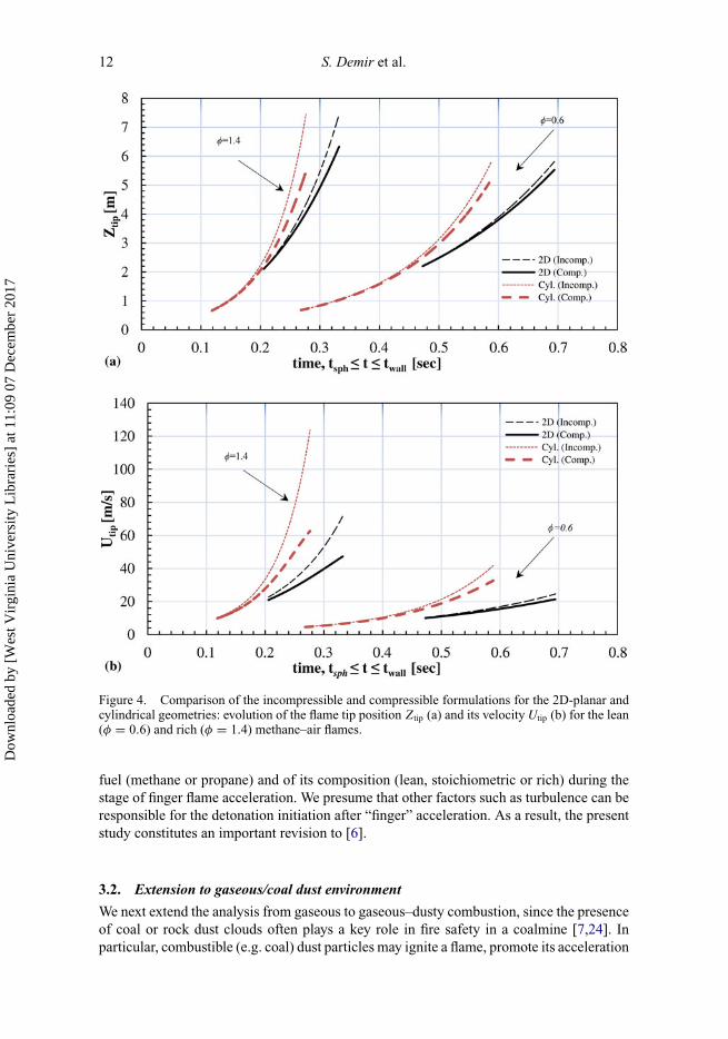
Figure 4 compares the 2D-planar and cylindrical-axisymmetric geometries for thesame thermal-chemical methane–air parameters. Specifically, the flame tip position, Ztip
(Figure 4(a)), and velocity, Utip (Figure 4(b)), are compared in the cases of lean (φ = 0.6)and rich (φ = 1.4) methane–air mixtures. It is seen that the effect of compressibility is higherfor the rich methane–air, due to a higher flame velocity. Overall, the role of compressibilityis stronger in a cylindrical geometry.
The most important conclusion of Figures 2(b), 3(b) and 4(b) is that the flame tipno longer attains the sound speed regardless of a configuration (2D or cylindrical), of a
Dow
nloa
ded
by [
Wes
t Vir
gini
a U
nive
rsity
Lib
rari
es]
at 1
1:09
07
Dec
embe
r 20
17
12 S. Demir et al.
Figure 4. Comparison of the incompressible and compressible formulations for the 2D-planar andcylindrical geometries: evolution of the flame tip position Ztip (a) and its velocity Utip (b) for the lean(φ = 0.6) and rich (φ = 1.4) methane–air flames.
fuel (methane or propane) and of its composition (lean, stoichiometric or rich) during thestage of finger flame acceleration. We presume that other factors such as turbulence can beresponsible for the detonation initiation after “finger” acceleration. As a result, the presentstudy constitutes an important revision to [6].
3.2. Extension to gaseous/coal dust environment
We next extend the analysis from gaseous to gaseous–dusty combustion, since the presenceof coal or rock dust clouds often plays a key role in fire safety in a coalmine [7,24]. Inparticular, combustible (e.g. coal) dust particles may ignite a flame, promote its acceleration
Dow
nloa
ded
by [
Wes
t Vir
gini
a U
nive
rsity
Lib
rari
es]
at 1
1:09
07
Dec
embe
r 20
17

Combustion Theory and Modelling 13
Figure 5. Comparison of the incompressible and compressible formulations for the 2D-planargeometry: evolution of the flame tip position Ztip (a) and its velocity Utip (b) for methane–air flames ofthe equivalence ratio φ = 0.7 in the presence of combustible dust of the concentration cd = 120 g/m3
and the mean particle radii rs = 10 µm, 75 µm.
and even trigger a detonation in some particular cases. On the other hand, inert dust particles(e.g. sand) may be helpful to prevent/mitigate the combustion process. Generally speaking,the laminar burning velocity SL may either increase or decrease in the presence of the coaldust. Indeed, on the one hand, SL is promoted by the impact of the volatiles released fromthe coal particles through the gaseous mixture, which appear an additional fuel source forthe combustion process. On the other hand, the coal dust particles gain heat from the flameduring the devolatilisation process, thereby acting as a heat sink [25]. Similar to [6], herewe employ the Seshadri formulation [26] for the coal-dust/gas laminar burning velocity:
Sd,L = 1
Ze
√2Bku
ρuCT
exp
(− Ea
RuTf
), Ze = Ea
(Tf − Tu
)RuT
2f
, (38)
Dow
nloa
ded
by [
Wes
t Vir
gini
a U
nive
rsity
Lib
rari
es]
at 1
1:09
07
Dec
embe
r 20
17
14 S. Demir et al.
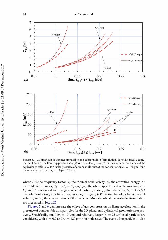
Figure 6. Comparison of the incompressible and compressible formulations for cylindrical geome-try: evolution of the flame tip position Ztip (a) and its velocity Utip (b) for the methane–air flames of theequivalence ratio φ = 0.7 in the presence of combustible dust of the concentration cd = 120 gm−3andthe mean particle radii rs = 10 µm, 75 µm.
where B is the frequency factor, ku the thermal conductivity, Ea the activation energy, Ze
the Zeldovich number, CT = Cp + CsVsnsρd/ρ the whole specific heat of the mixture, withCp and Cs associated with the gas and coal particle, ρ and ρd their densities, Vs = 4πr3
s /3the volume of a single particle of radius rs , ns = (cd/ρd )/Vs the number of particles per unitvolume, and cd the concentration of the particles. More details of the Seshadri formulationare presented in [6,25,26].
Figures 5 and 6 demonstrate the effect of gas compression on flame acceleration in thepresence of combustible dust particles for the 2D-planar and cylindrical geometries, respec-tively. Specifically, small (rs = 10 µm) and relatively larger (rs = 75 µm) coal particles areconsidered, with φ = 0.7 and cd = 120 g m–3 in both cases. The event of no particles is also
Dow
nloa
ded
by [
Wes
t Vir
gini
a U
nive
rsity
Lib
rari
es]
at 1
1:09
07
Dec
embe
r 20
17

Combustion Theory and Modelling 15
Figure 7. Comparison of the incompressible and compressible formulations for the 2D-planar andcylindrical geometries: the maximal coordinate Ztip(twall) (a, c) and velocity Utip(twall) (b, d) versusthe combustible (a, b) and inert (c, d) particle concentration for φ = 0.7 and the mean particle radiusrs = 25 µm.
presented. For comparison, the results of the incompressible formulation [6] are also shown.Overall, it is seen that the combustible dust promotes the flame velocity, and the smallerthe particles, the stronger acceleration is. According to Figure 5(a), the relative reduction inZtip(twall) due to gas compression is 18% for rs = 10 µm, 14.4% for rs = 75 µm and 13.6%for the event of no dust. As for the flame tip velocity (Figure 5(b)), the relative reductionin Utip(twall) constitutes 51% for rs = 10 µm, 34% for rs = 75 µm and 32% for no dust.Figure 6 is a counterpart of Figure 5 for cylindrical-axisymmetric geometry. In Figure 6(a),the relative reduction in Ztip(twall) due to gas compression is 39% for rs = 10 µm, 27% forrs = 75 µm, and 26% for the event of no dust. As for the flame tip velocity (Figure 6(b)),the relative reduction in Utip(twall) constitutes 68% for rs = 10 µm, 50% for rs = 75 µm and48% for no dust. Consequently, gas compression moderates methane/air/coal-dust flameacceleration, and the effect appears even stronger than that for gaseous combustion.
The maximal flame tip position and velocity attained during finger flame acceleration,i.e. when the flame skirt contacts the passage wall, Ztip(twall) and Utip(twall), are presentedversus the particle concentration in Figure 7, for rs = 25 µm and φ = 0.7 in the 2D-planar
Dow
nloa
ded
by [
Wes
t Vir
gini
a U
nive
rsity
Lib
rari
es]
at 1
1:09
07
Dec
embe
r 20
17

16 S. Demir et al.
Figure 8. Comparison of the incompressible and compressible formulations for the 2D-planargeometry: evolution of the flame tip position Ztip (a) and its velocity Utip (b) for the methane–airflames of equivalence ratio φ = 0.7 in the presence of the combustible, inert and combined particlesof the concentration cd = 120 g m–3 and the mean particle radius rs = 25 µm.
and cylindrical-axisymmetric geometries. Here, Figure 7(a) and 7(b) are devoted to thecombustible particles, while the case of inert particles is shown in Figure 7(c) and 7(d). Itcan be seen that unlike the particle size, the concentration influences the flame dynamicsweaker: the effect is minor for a combustible dust, and it is moderate for the inert particles.
Finally, the flame evolutions in the situations of no dust, combustible dust, inertdust, and their combination are compared in Figures 8 and 9 for the 2D-planar andcylindrical-axisymmetric geometries, respectively, for φ = 0.7, cd = 120 g m–3, and
Dow
nloa
ded
by [
Wes
t Vir
gini
a U
nive
rsity
Lib
rari
es]
at 1
1:09
07
Dec
embe
r 20
17

Combustion Theory and Modelling 17
Figure 9. Comparison of the incompressible and compressible formulations for the cylindricalgeometry: evolution of the flame tip position Ztip (a) and its velocity Utip (b) for the methane–airflames of the equivalence ratio φ = 0.7 in the presence of combustible, inert and combined particlesof the concentration cd = 120 g m–3 and the mean particle radius rs = 25 µm.
rs = 25 µm in both cases. It is observed that the combustible and inert particles pro-vide noticeable deviations from the no-dust curves by promoting (combustible dust) ormoderating (inert dust) flame acceleration. When both combustible and inert particles arepresent in the mixture, their impacts oppose each other such that their net effect resemblesthat of no dust. Still, the relative effect of the combustible dust exceeds that of the inertone. The influence of gas compression is also seen. Quantitatively, in a 2D-planar geometry(Figure 8(a)), the relative reduction in Ztip(twall) due to gas compression is 14% for no dust,
Dow
nloa
ded
by [
Wes
t Vir
gini
a U
nive
rsity
Lib
rari
es]
at 1
1:09
07
Dec
embe
r 20
17

18 S. Demir et al.
Figure 10. Comparison of the incompressible and compressible formulations for the 2D-planar andcylindrical geometries: evolution of the flame tip position Ztip (a) and its velocity Utip (b) for themethane–air flames of the equivalence ratio φ = 0.7 in the presence of the combustible, inert andcombined particle of the concentration cd = 120 g m–3 and the mean particle radius rs = 25 µm.
10% for the inert dust, 17% for the combustible dust and 13% for their combination. As forthe associated flame tip velocity (Figure 8(b)), here gas compression provides the relativereduction in Utip(twall) of 32% for no dust, 23% for the inert dust particles, 39% for thecombustible particles, and 30% for their combination. As for the cylindrical-axisymmetricgeometry (Figure 9), Ztip(twall) reduces, due to gas compression, by 25% for no dust, 19%for the inert dust, 31% for the combustible dust and 24% for their combination, as shownin Figure 9(a). Similarly, Utip(twall) (Figure 9(b)) reduces due to gas compression by 48%
Dow
nloa
ded
by [
Wes
t Vir
gini
a U
nive
rsity
Lib
rari
es]
at 1
1:09
07
Dec
embe
r 20
17

Combustion Theory and Modelling 19
for no dust, 36% for the inert dust, 56% for the combustible dust and 45% for their com-bination. If a mixture composition approaches the stoichiometry, φ = 1, then the relativereduction in Ztip and Utip due to gas compression is expected to increase, as discussed in theprevious section. Finally, the effect of geometry is shown in Figure 10 for the combustibleand inert particles. It is seen that the impact of gas compression is stronger in the cylindricalgeometry. Additionally, during the time interval tsph ≤ t ≤ twall, a flame elongates strongerin the cylindrical geometry than in the 2D one, and this range is smaller for the combustibleparticles due to fast pyrolysis ability.
4. Conclusions
In this work, the incompressible theory of methane/air/dust flame acceleration in a coalmin-ing passage [6] is revisited by incorporating the effect of gas compression into the analysis,which may be an identification of the applicability and the limitations of the incompressibletheory [6]. It is shown that gas compression moderates flame acceleration, and its impactdepends on a type of the fuel, geometry and various thermal-chemical parameters. Therelative role of compression, as compared to the predictions [6], is quantified for a varietyof parameters such as φ, rs , cd , and it appeared stronger for gaseous–dusty environmentsas compared to purely gaseous ones.
As a result, the intrinsic accuracy of the formulation [6] for a given set of parameters wasidentified. Specifically, moderation of flame acceleration due to gas compression is seenmore effective in stoichiometric mixtures such that the decrease in the maximal flame tipposition Ztip(twall) varies in the range 43–69% for methane–air and propane–air flames. Thismoderation is relatively minor for the lean (φ = 0.63) and rich (φ = 1.4) mixtures, being5–22% and 15–47%, respectively. It is also noted that while flames accelerate faster in acylindrical geometry, moderation of acceleration due to compressibility is also larger in thisgeometry than in a 2D case. Furthermore, such moderation reduces the flame tip velocityUtip(twall) far beyond the speed of sound, irrespective of the type of a fuel, equivalence ratioand geometry in contrast to the incompressible predictions [6].
The analysis was then extended from gaseous to gaseous–dusty combustion. Specifi-cally, both combustible and inert dust particles, as well as their combination, were consid-ered, and it is shown how the particle size and the concentration of the particles influencethe flame dynamics and the compressibility effect. Namely, the role of compressibility isstronger for small particles, rs = 10 µm, than for rs = 75 µm. Although the particle con-centration is less influential for the effect of gas compression than the particle size, it isnoted that the role of compressibility nevertheless strengthens with the increasing concen-tration of the combustible particles. In contrast, the effect of compressibility decreases withthe increasing concentration of the inert particles.
Finally, it is recalled that both [6] and the present analysis are only a steps towardsmodelling the comprehensive coalmining flame evolution scenario, with numerous factorsleft beyond the study yet. For example, the flame evolution can be influenced, positively ornegatively, by the different motions of dust particles. In particular, this may lead to a non-uniform distribution of dust concentration and thereby spatial and/or temporal variationsof the local thermal-chemical parameters such as the equivalence ratio and the laminarburning velocity. This is indeed the case in coalmines, where the coal dust distribution istypically non-uniform and a steady dense coal dust layer may spread through the bottomof the passage. The analysis of how local variations of the burning properties influence theglobal flame propagation scenario constitutes a separate study; see for instance [27,28]. Inaddition, the present analysis is conceptually laminar, while a real fire flame in a coalmine
Dow
nloa
ded
by [
Wes
t Vir
gini
a U
nive
rsity
Lib
rari
es]
at 1
1:09
07
Dec
embe
r 20
17
20 S. Demir et al.
is presumably turbulent. The role of turbulence may potentially be incorporated into thepresent formulation by replacing the planar flame velocity SL by a local turbulent burningvelocity ST , with the ratio ST /SL found analytically, phenomenologically, experimentallyor computationally, from a relevant turbulent flame speed model. This, however, requires aseparate study and will be presented elsewhere.
AcknowledgementsThe authors thank Ali S. Rangwala of Worcester Polytechnic Institute for useful discussions. This workis sponsored by the US National Science Foundation (NSF), through the CAREER Award #1554254(V.A.), prior to which this research was supported by the Alpha Foundation for the Improvementof Mine Safety & Health, Inc., through the Award #AFSTI14-05 (V.A). The views, opinions andrecommendations expressed herein are solely those of the authors and do not imply any endorsementby the Alpha Foundation, its directors and staff.
Disclosure statementNo potential conflict of interest was reported by the authors.
FundingAlpha Foundation for the Improvement of Mine Safety & Health, Inc. [grant number #AFSTI14-05];US National Science Foundation (NSF) [grant number CAREER #1554254].
References[1] K.L. Cashdollar, M.J. Sapko, E.S. Weiss, M.L. Harris, C.K. Man, S.P. Harteis, and G.M. Green,
Recommendations for a New Rock Dusting Standard to Prevent Coal Dust Explosions in IntakeAirways, Pittsburgh, 2010.
[2] K. Chatrathi, J.E. Going, and B. Grandestaff, Flame propogation in industrial scale piping,Process Saf. Prog., 20 (4) (2001), pp. 286–294.
[3] M. Bi, C. Dong and Y. Zhou, Numerical simulation of premixed methane-air deflegration inlarge L/D closed pipes, Appl. Therm. Eng., 40 (2012), pp. 337–342.
[4] R.W. Houim and E.S. Oran, Structure and flame speed of dilute and dense layered coal-dustexplosions, J. Loss Prev. Process Ind., 36 (2015), pp. 214–222.
[5] X. Chen, Y. Zhang, and Y. Zhang, Effect of CH4-air ratios on gas explosion flame microstructureand propogation behaviors, Energies, 5 (2012), pp. 4132–4146.
[6] S. Demir, V. Bychkov, S. Chalagalla, and V. Akkerman, Towards a predictive scenario of aburning accident in a mining passage, Combust. Theory Modelling 21 (2017), pp. 997–1022.
[7] S. Rockwell and A.S. Rangwala, Influence of coal dust on premixed turbulent methane–airflames, Combust. Flame, 160 (2013), pp. 635–640.
[8] V. Akkerman, C.K. Law, and V. Bychkov, Self-similar accelerative propogation of expendingwrinkled flames and explosion triggering, Phys. Rev. E, 83 (2011), pp. 026305.
[9] C. Clanet and G. Searby, On the "tulip flame" phenomenon, Combust. Flame, 105 (1996),pp. 225–238.
[10] V. Bychkov, V. Akkerman, G. Fru, A. Petchenko, and L.E. Eriksson, Flame acceleration in theearly stages of burning in tubes, Combust. Flame, 150 (2007), pp. 263–276.
[11] D. Valiev, V. Akkerman, M. Kuznetsov, L.E. Eriksson, C.K. Law, and V. Bychkov, Influence ofgas compression on flame acceleration in the early stage of burning in tubes, Combust. Flame,160 (2013), pp. 97–111.
[12] H. Xiao, R.W. Houim, and E.S. Oran, Formation and evolution of distorted tulip flames,Combust. Flame, 162 (11) (2015), pp. 4084–4101.
[13] V. Akkerman, V. Bychkov, A. Petchenko, and L.E. Eriksson, Accelerating flames in cylindricaltubes with nonslip at the walls, Combust. Flame, 145 (2006), pp. 206–219.
Dow
nloa
ded
by [
Wes
t Vir
gini
a U
nive
rsity
Lib
rari
es]
at 1
1:09
07
Dec
embe
r 20
17
Combustion Theory and Modelling 21
[14] D. Valiev, V. Bychkov, V. Akkerman, L.E. Eriksson, Flame acceleration in channels withobstacles in the deflegration-to-detonation transition, Combust. Flame, 157 (2010), pp. 1012–1021.
[15] M. Liberman, M. Ivanov, A. Kiverin, M. Kuznetsov, A. Chukalovsky, and T. Rakhimova,Deflagration-to-detonation transition in highly reactive combustible mixtures, Acta Astronaut.,67 (2010), pp. 688–701.
[16] G. Ciccarelli and S. Dorofeev, Flame acceleration and transition to detonation in ducts, Prog.Energy Combust. Sci., 34 (2008), pp. 499–550.
[17] M. Kuznetsov, M. Liberman, and I. Matsukov, Experimental study of the preheat zone formationand deflagration to detonation transition, Combust. Sci. Technol., 182 (2010), pp. 1628–1644.
[18] M.A. Liberman, G.I. Sivashinsky, D.M. Valiev, and L.E. Eriksson, Numerical simulationof deflagration-to-detonation transition: the role of hydrodynamic instability, Int. J. Transp.Phenom., 8 (3) (2006), pp. 253–277.
[19] E. Oran and V.N. Gamezo, Origins of the deflagration-to-detonation transition in gas-phasecombustion, Combust. Flame, 148 (2007), pp. 4–47.
[20] V. Bychkov, V. Akkerman, D. Valiev, and C.K. Law, Role of compressibility in moderatingflame acceleration in tubes, Phys. Rev. E, 81 (2010), pp. 026309.
[21] S. Davis, J. Quinard and G. Searby, Markstein numbers in counterflow methane- and propane-air flames: a computational study, Combust. Flame, 130 (2002), pp. 123–136.
[22] V. Akkerman and V. Byckhov, Turbulent flame and the Darrieus-Landau instability in a three-dimensional flow, Combust. Theory Modelling, 7 (2003), pp. 767–794.
[23] J.D. Anderson, Modern Compressible Flow: with Historical Perspective, 2nd Edition ed., NewYork: McGraw-Hill, 1990, pp. 233–234.
[24] M. Wu, M. Burke, S. Son, and R. Yetter, Flame acceleration and the transition to detonation ofstoichiometric ethylene/oxygen in microscale tubes, Proc. Combust. Inst. 31 (2007), p. 2429.
[25] Y. Xie, V. Ranghavan, and A.S. Rangwala, Study of interaction of entrained coal dust particlesin lean methane-air premixed flames, Combust. Flame, 159 (2012), pp. 2449–2456.
[26] K. Seshadri, A.L. Berlad, and V. Tanirala, The structure of premixed particle-cloud flames,Combust. Flame, 89 (1992), pp. 333–342.
[27] S. Demir, H. Sezer, and V. Akkerman, Effect of local variations of the laminar flame speed onthe global finger-flame acceleration scenario, Combust. Theory Modelling (2017), submitted.
[28] S. Demir, H. Sezer, T. Bush, and V. Akkerman, Promotion and Mitigation of Premixed FlameAcceleration in Dusty-Gaseous Environment with Various Combustible Dust Distributions: AComputational Study, 26th ICDERS, Boston, USA, 30 July – 4 August 2017.
Dow
nloa
ded
by [
Wes
t Vir
gini
a U
nive
rsity
Lib
rari
es]
at 1
1:09
07
Dec
embe
r 20
17