Embed Size (px)
Citation preview

application deadline:–
RefeRence: Nova Bus Manualssection: 09: Engine and coolingRs no: MQR 7621-346effective in pRod.: L647 (2012MR)
MateRialqty paRt no Rev. descRiption Replaces paRt n°
level 11 N65114 – Surge tank cap N362421 N66783 – Support LH Radiator Assembly N43209-11 N66782 – Support RH Radiator Assembly N43209-24 N37749 – Dual Clamp Tie –2 N66397 – 3/8" Spacer –8 N16891 – Bolt –4 N66725 – Thin Spacer –
2(1) N36496 – Washer –4 N43343 – Radiator Mount –
1(2) – – Leveling Jig (2) –1 N8899180 – Right Lower Support –1 N8899181 – Left Lower Support –
(1) Quantity is an estimation. Quantity will be determined according to radiator support leveling requirements. (2) Contact your After-Sales Representative for part details and availability.level 2
– – – – –Materials will be available within 84 days. To order, please contact Prevost Parts by phone at 1-800-771-6682, by fax at 1-888-668-2555 or by email at [email protected]. Specify document number, quantity of parts required and shipping address.
level descRiptiondiRect cHaRGes
tiMelabouR MateRial
1 Leveling of the radiator assembly and replace surge tank cap with the new replacement cap N65114 Client Client 5h45
2 – – – –
subject: Radiator Assembly anchorage and surge tank cap
justification: New procedure for the radiator assembly anchorage levelling to optimize the filling of the coolant and surge tank cap N36242 replace by N65114
appRoved by:
sav.1E.2012Ma
LI1861E
paGe 1 of 13
InformatIon letter

client oRdeRRoad nuMbeR vin (2Nvy/4RKy...)
qtyfRoM to fRoM to
Belleville Transit - Ontario L598 — — L82U5A3000581 L82U7A3000582 2
Calgary Transit - Alberta L601 8101 8114 L82U5A4000099 L82U4A4000112 14
Calgary Transit - Alberta L607 8115 8130 L82UXA3000477 L82U6A3000492 16
Calgary Transit - Alberta L615 8131 8158 L82U1B4000019 L82U4B4000046 28
Connecticut Transit - Connecticut L554 1041 1054 S92U1A4000139 S92U4A4000152 14
Connecticut Transit - Connecticut L554 1055 1065 S92U8A4000154 S92U0A4000164 11
Guelph - Ontario L579 221 224 L82UXA3000401 L82U5A3000404 4
Halifax - Nova Scotia L558 717 731 S92UXA3000293 S92U6A3000307 15
Halifax - Nova Scotia L613 732 741 S92UXB3000019 S92UXB3000028 10
Marketing Sales Demo - MSD 4 L568 — — S92U9B3000013 S92U9B3000013 1
New york City Transit - New york L608 8000 8014 L82U6B4000047 L82U0B4000061 15
New york City Transit - New york L620 8015 8029 L82U2B4000062 L82U2B4000076 15
New york City Transit - New york L620 8030 8074 L82U8B4000079 L82U7B4000123 45
New york City Transit - New york L643 8090 8090 S92U1B4000143 S92U1B4000143 1
New york City Transit - New york L670 5771 5784 S92U9B4000147 S92U1B4000160 14
New york City Transit - New york L670 5785 5857 S92U4B4000170 S92U3B4000242 73
New york City Transit - New york L670 5858 5896 S92U9B4000147 S92U1B4000160 38
New york City Transit - New york L681 5896 5896 S92U2C4500023 S92U2C4500023 1
Strathcona County Transit - Alberta L580 2011 2023 L82U1A3000464 L82U8A3000476 13
Thunder Bay - Ontario L614 — — L82UXB3000061 L82U3B3000063 3
york Regional Transit - Ontario L562 1080 1082 S92U2A3000420 S92U6A3000422 3
york Regional Transit - Ontario L572 1083 1094 S92U3A3000569 S92U2A3000580 12
Revision HistoRyRev. date cHanGe descRiption wRitten by
NR 2013MA17 Initial release Luc Carignan
sav.1E.2012Ma
LI1861E
paGe 2 of 13
InformatIon letter

pRoceduRe
1.1. Remove the radiator access door. Retain the hardware. See Figure 1.
WARNING
follow your internal safety procedures.
Hydraulic cylinders
Figure 1 - Typical Anchorage for the Radiator Access Door
WARNING
before starting any work on the radiator, make sure the vehicle is completely stationary. isolate the engine starting circuit from the control box located at the rear of the vehicle.
cleanliness is vital when working on the hydraulic system.
1.2. Remove the surge tank cap.1.3. Install the new cap N65114 on the surge tank.1.4. Open the engine access door.1.5. Fill the cooling system according to filling procedure of section 09-302: EnginE Cooling of the Nova Bus
Maintenance Manual.1.6. Close the stop valve to isolate the engine and heating cooling circuit.1.7. Connect a regulator valve equipped with a pressure gauge on the quick connect fitting.
sav.1E.2012Ma
LI1861E
paGe 3 of 13
InformatIon letter

1.8. Adjust the pressure to 15 psi and close air pressure inlet. Make sure the pressure remains constant for 5 minutes.1.9. If the pressure does not remain constant verify if liquid and/or air is leaking from the overflow hose.
1.9.1. If liquid and/or air is leaking from the overflow hose, perform steps 1.35 to 1.38 for the replacement of the surge tank and order a new surge tank N56950.
1.9.2. If there is no liquid and/or air leaking from the overflow hose, proceed with the proper correction to repair the engine cooling circuit.
1.10. Drain the various fluids from the hydraulic and cooling circuit, disconnect the piping to the radiator, and remove the radiator assembly according to the drain and removal procedures of sections 09-304: HydrauliC SyStEm and 09-302: EnginE Cooling of the Nova Bus Maintenance Manual.
1.11. Place the radiator assembly in a secure and accessible area.1.12. Remove the isolators from the support. Retain the hardware. See Figure 2
Figure 2 - Isolators Identification
Front left isolator Front right isolator
Rear right isolator
Rear left isolator
1.13. Move the cooling fluid pipe located on the left side of the vehicle in order to avoid contact with the leveling jig. It is recommended to remove the rear light panels located on each side of the rear shell to gain access to the piping anchor points.
sav.1E.2012Ma
LI1861E
paGe 4 of 13
InformatIon letter

1.14. Replace the front supports with new upper supports N66783 (left support) and N66782 (right support) using the retained mounting bolts. Apply Loctite 242 thread locker or the equivalent to the bolts. See Figure 3.
Figure 3 - Upper Black Support (Left Side Shown/ Right Side Similar)
Black support to be replaced
Mounting bolt (x4)
Torque: 35 lb-ft (47N•m)
1.15. Make sure that the hydraulic pipe brackets, located in rear portion of the radiator compartment, are still bonded to the rear shell. See Figure 4.
Figure 4 - Hydraulic Pipe Brackets
sav.1E.2012Ma
LI1861E
paGe 5 of 13
InformatIon letter
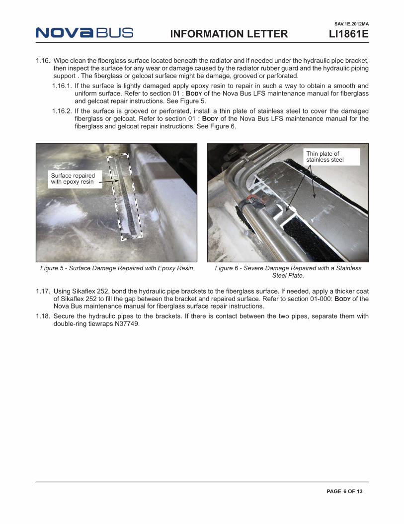
1.16. Wipe clean the fiberglass surface located beneath the radiator and if needed under the hydraulic pipe bracket, then inspect the surface for any wear or damage caused by the radiator rubber guard and the hydraulic piping support . The fiberglass or gelcoat surface might be damage, grooved or perforated.1.16.1. If the surface is lightly damaged apply epoxy resin to repair in such a way to obtain a smooth and
uniform surface. Refer to section 01 : Body of the Nova Bus LFS maintenance manual for fiberglass and gelcoat repair instructions. See Figure 5.
1.16.2. If the surface is grooved or perforated, install a thin plate of stainless steel to cover the damaged fiberglass or gelcoat. Refer to section 01 : Body of the Nova Bus LFS maintenance manual for the fiberglass and gelcoat repair instructions. See Figure 6.
Surface repaired with epoxy resin
Thin plate of stainless steel
Figure 5 - Surface Damage Repaired with Epoxy Resin Figure 6 - Severe Damage Repaired with a Stainless Steel Plate.
1.17. Using Sikaflex 252, bond the hydraulic pipe brackets to the fiberglass surface. If needed, apply a thicker coat of Sikaflex 252 to fill the gap between the bracket and repaired surface. Refer to section 01-000: Body of the Nova Bus maintenance manual for fiberglass surface repair instructions.
1.18. Secure the hydraulic pipes to the brackets. If there is contact between the two pipes, separate them with double-ring tiewraps N37749.
sav.1E.2012Ma
LI1861E
paGe 6 of 13
InformatIon letter

1.19. Install a 3/8'' spacer N66397 and new isolator N43343 using N16891 bolts and retained hardware on both rear supports of the structure. Apply Loctite 242 thread locker or the equivalent on the bolts. Do not tighten the bolts. See Figure 7.
Figure 7 - Installation of Spacers N66397 on the Lower Supports
Lower Isolator
Spacer N66397
1.20. Install new isolator N43343 on the front support. Apply Loctite 242 thread locker or the equivalent on the bolts. Do not tighten the bolts.
1.21. Install the leveling jig onto the isolators. Secure the jig to the isolators with the centering pins. See Figure 8.
Figure 8 - Leveling Jig
sav.1E.2012Ma
LI1861E
paGe 7 of 13
InformatIon letter

1.22. Ensure the jig is level and sits properly on both lower isolators. If there is a gap between the jig and the upper isolators, insert one or a few thin spacers (N66725) or a combination of thin and thick spacers (N66397) in order to fill the gap.
1.23. Remove the leveling jig and place in a secure area.1.24. Remove the bolts and isolators which require leveling.1.25. Place the spacers measured with the leveling jig between the support and the isolator. The retained bolts might
be too short due to the new spacer. If needed use N16891 bolts in a way to obtain two threads beyond the nuts.1.26. Ensure proper installation by mounting the leveling jig onto the isolators. The jig should sit properly on all four
isolators. If needed add or remove spacers to readjust.1.27. Begin tightening the bolts according to the following sequence:
1.27.1. Tighten the rear bolt of the upper left isolator. 1.27.2. Tighten the rear bolt of the lower right isolator. 1.27.3. Tighten the rear bolt of the lower left isolator. 1.27.4. Tighten the rear bolt of the upper right isolator. 1.27.5. Repeat the sequence for the front bolt of all four isolators.
1.28. Remove the levelling jig and set aside in a secure area.1.29. Repeat the tightening sequence of step 1.26 by applying a tightening torque of 35 ft-lb (47N•m) on the isolator
bolts. See Figure 12.1.30. Remove the radiator spider assembly and the shroud from the radiator. See Figure 9.
Figure 9 - Radiator Assembly
Hydraulic Motor
Radiator Guard
Fan Blades
Shroud
sav.1E.2012Ma
LI1861E
paGe 8 of 13
InformatIon letter

1.31. Replace the lower support of the radiator assembly with the new right support N8899180 and left N8899181. See Figure 10.
Figure 10 - Lower Supports to Replace
NOTE
steps 1.32 to 1.35 should be performed only if the pressure test in step 1.9 shows a leak on the surge tank.
1.32. Remove the surge tank from the radiator. Retain the hardware and the new cap N65114. 1.33. Remove all the parts installed on the removed surge tank.1.34. Install the parts removed from the old surge tank on the new surge tank. Respect the original orientation of
the parts.1.35. Install the new surge tank equipped with cap N65114 on the radiator using the retained hardware.
sav.1E.2012Ma
LI1861E
paGe 9 of 13
InformatIon letter
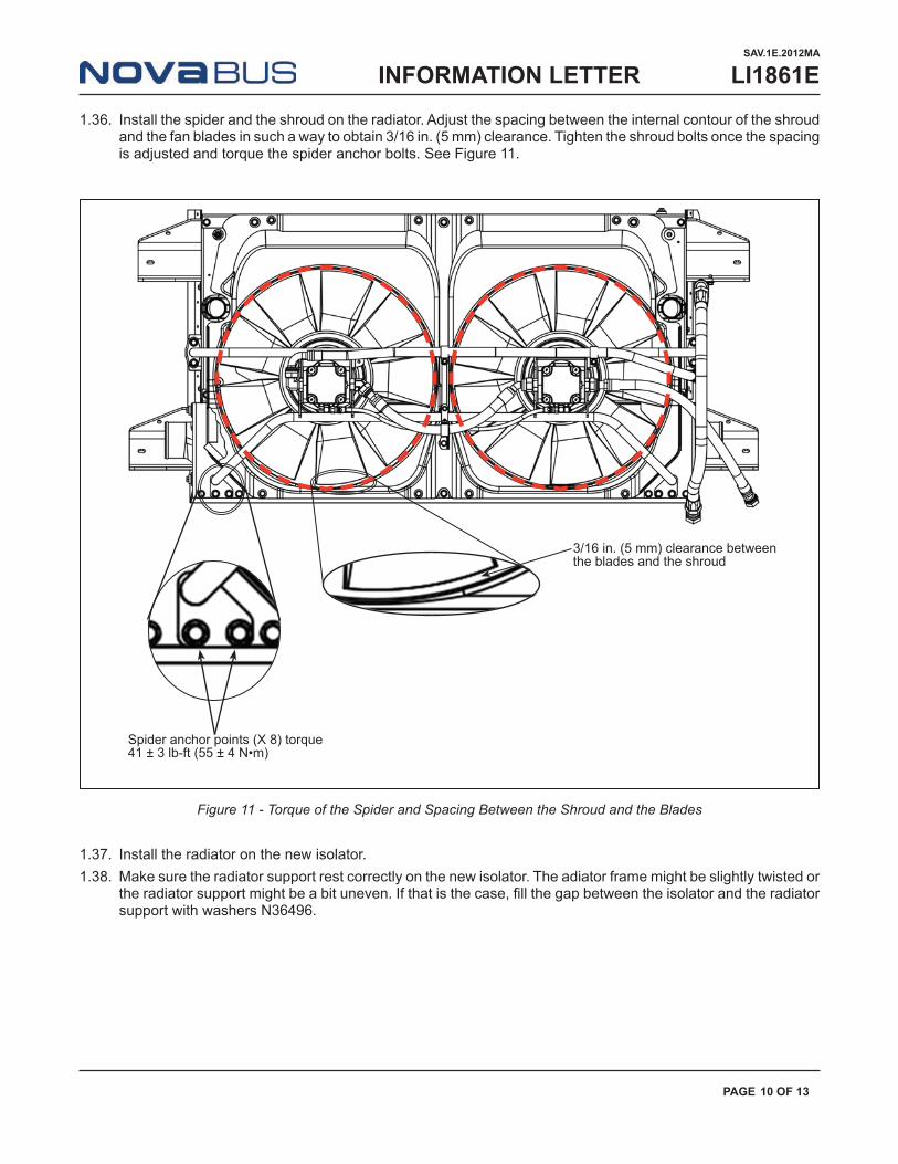
1.36. Install the spider and the shroud on the radiator. Adjust the spacing between the internal contour of the shroud and the fan blades in such a way to obtain 3/16 in. (5 mm) clearance. Tighten the shroud bolts once the spacing is adjusted and torque the spider anchor bolts. See Figure 11.
3/16 in. (5 mm) clearance between the blades and the shroud
Spider anchor points (X 8) torque 41 ± 3 lb-ft (55 ± 4 N•m)
Figure 11 - Torque of the Spider and Spacing Between the Shroud and the Blades
1.37. Install the radiator on the new isolator. 1.38. Make sure the radiator support rest correctly on the new isolator. The adiator frame might be slightly twisted or
the radiator support might be a bit uneven. If that is the case, fill the gap between the isolator and the radiator support with washers N36496.
sav.1E.2012Ma
LI1861E
paGe 10 of 13
InformatIon letter

NOTE
Radiator mounting support holes and isolators might not align correctly. to obtain proper alignment, loosen the isolator anchor bolts and move the isolator in such a way to line up with the mounting support holes. torque the isolator anchor bolts to 35 ± 3 lb-ft (47 ± 4 n•m). see figure 12.
1.39. Apply Loctite 242 thread locker type or the equivalent on the radiator anchor bolts.1.40. Place the anchor bolts and pre-tighten.1.41. Apply the torque specified in Figure 12.
Figure 12 - Radiator Installation and Torque Value
22 ±4 lb-ft (30 ± 5 N•m)
35 ±3 lb-ft(47 ± 4 N•m)
22 ±4 lb-ft (30 ± 5 N•m)
35 ±3 lb-ft(47 ± 4 N•m)
1.42. Connect all the hoses and accessories on the radiator.
NOTE
install and tighten the piping according to the procedure indicated in section 99 : gEnEral praCtiCES of the nova bus lfs maintenance manual and as indicated in figures 13 to 15.
sav.1E.2012Ma
LI1861E
paGe 11 of 13
InformatIon letter

Figure 14 - Cooling System Piping
Figure 15 - Hydraulic System Lines
Figure 16 - Air Cooling System Lines
Torque:12 ± 1.5 lb-ft(17 ± 2 N•m)
sav.1E.2012Ma
LI1861E
paGe 12 of 13
InformatIon letter

1.43. Fill the system affected by the removal of the radiator as indicated in section 09-302 : EnginE Cooling, t-drivE and 09-304 HydrauliC SyStEm, t-drivE of the Nova Bus LFS maintenance manual.
1.44. Check all connections for any potential leaks. Repair if necessary.1.45. Open the stop valve of the engine and heating system.
WARNING
failure to repair any leaking component of the cooling system, such as a pump, valve, tube or the motor could result in a fire.
1.46. Close the engine door. 1.47. Install the radiator access door using the retained hardware. See Figure 1.
sav.1E.2012Ma
LI1861E
paGe 13 of 13
InformatIon letter