Embed Size (px)
Citation preview
Initial Implementation of Near-Body Grid Adaption
in OVERFLOW
Pieter G. Buning
NASA Langley Research Center, Hampton, VANASA Langley Research Center, Hampton, VA
and
Thomas H. Pulliam
NASA Ames Research Center, Moffett Field, CA
11th Symposium on Overset Composite Grid and Solution Technology
October 15-18, 2012, Dayton, OH
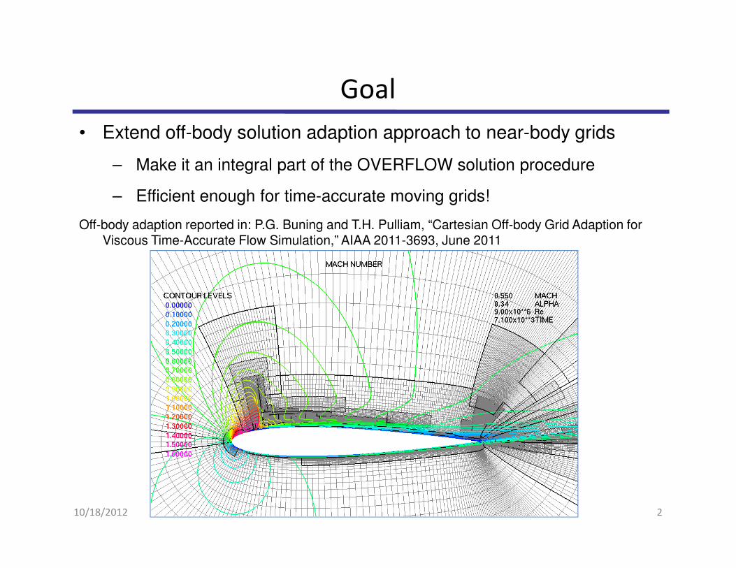
Goal
• Extend off-body solution adaption approach to near-body grids
– Make it an integral part of the OVERFLOW solution procedure
– Efficient enough for time-accurate moving grids!
Off-body adaption reported in: P.G. Buning and T.H. Pulliam, “Cartesian Off-body Grid Adaption for Viscous Time-Accurate Flow Simulation,” AIAA 2011-3693, June 2011
210/18/2012

Outline
• (Goal)
• Approach
– Sensor function and marking
– Grid generation and connectivity
– Grid and solution interpolation
3
– Grid and solution interpolation
• Examples
• Issues
– Topology limitations
– Parametric cubic interpolation
• Summary and future work
10/18/2012

Approach
• Use the same approach as for off-body adaption, just in computational space instead of Cartesian space
– Refinement is isotropic
– Where we have refinement regions, blank out coarser-level regions
– Neighboring refinement regions differ by only 2x in spacing
– Use parametric cubic interpolation to form refined grids (more later)
410/18/2012

Approach
Controls:
• NREFINE – maximum number of refinement levels
• NBREFINE – number of near-body refinement levels, if different
• ETYPE – sensor function (undivided 2nd difference, vorticity, undivided vorticity...)
5
• EREFINE – sensor value above which we mark for refinement
• ECOARSEN – sensor value below which we mark for coarsening
• Specify near-body regions to explicitly refine
• Specify near-body regions to limit refinement
10/18/2012
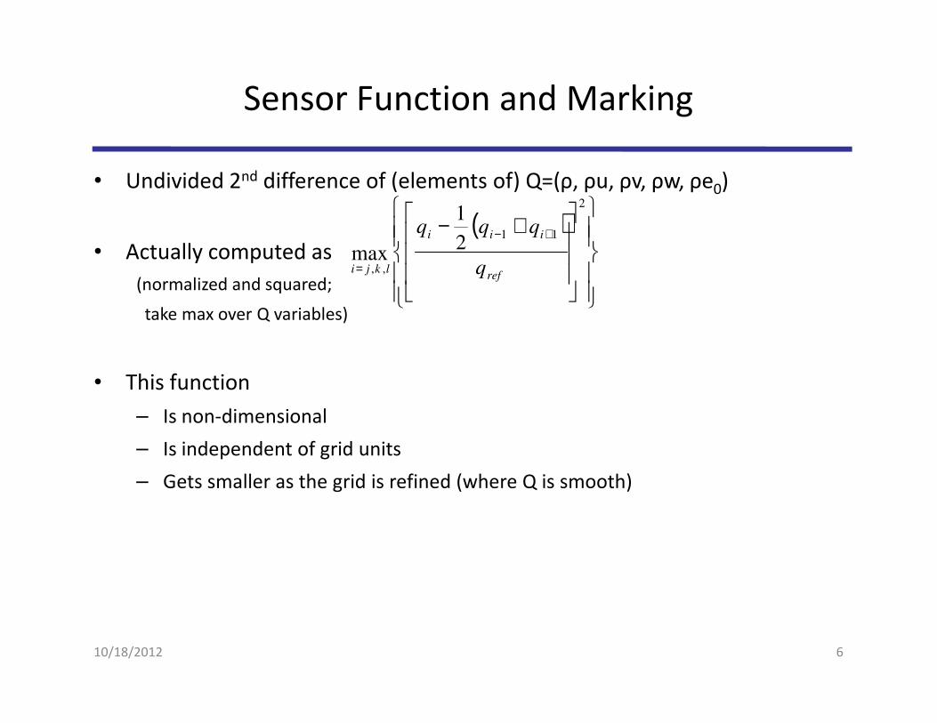
Sensor Function and Marking
• Undivided 2nd difference of (elements of) Q=(ρ, ρu, ρv, ρw, ρe0)
• Actually computed as
(normalized and squared;
take max over Q variables)
( )
+− +−
=
2
11
,,
2
1
maxref
iii
lkji q
qqq
6
• This function
– Is non-dimensional
– Is independent of grid units
– Gets smaller as the grid is refined (where Q is smooth)
10/18/2012
Sensor Function and Marking
• At each grid point
– If the sensor function value exceeds a refinement tolerance, mark for grid
refinement;
– If it falls below a coarsening tolerance, mark for grid coarsening
• Within an 8x8x8 grid cube, or “box”
7
– If any point votes for refinement, the box is marked for refinement;
– If all points vote for coarsening, the box is marked for coarsening
• Regions can only coarsen or refine by one level at a time
10/18/2012

Grid Generation
• Parametric cubic interpolation vs. linear interpolation
– Preserves smooth geometry
Pressure contours
810/18/2012
Linear interpolationParametric cubic interpolation

Grid Generation
• Parametric cubic interpolation vs. linear interpolation
– Preserves grid stretching
Computational grid
910/18/2012
Parametric cubic interpolation Linear interpolation

Grid Connectivity
• Hole cutting
– All refinement regions get cut by geometry
(just like original near-body grid)
• Blanking for refinement
– Next-finer grid level explicitly blanks out
regions in current level
• Connectivity
10
• Connectivity
– Refinement regions can have
• Hole boundary points from geometry cuts
• Hole boundary points from finer refinement
grids
• Outer boundary points (connecting to same-
or coarser-level regions)
• Outer boundary points (connecting to other
near-body or off-body grids)
• Boundary conditions inherited from original
near-body grid
Sample grid blanking
for refinement regions
10/18/2012
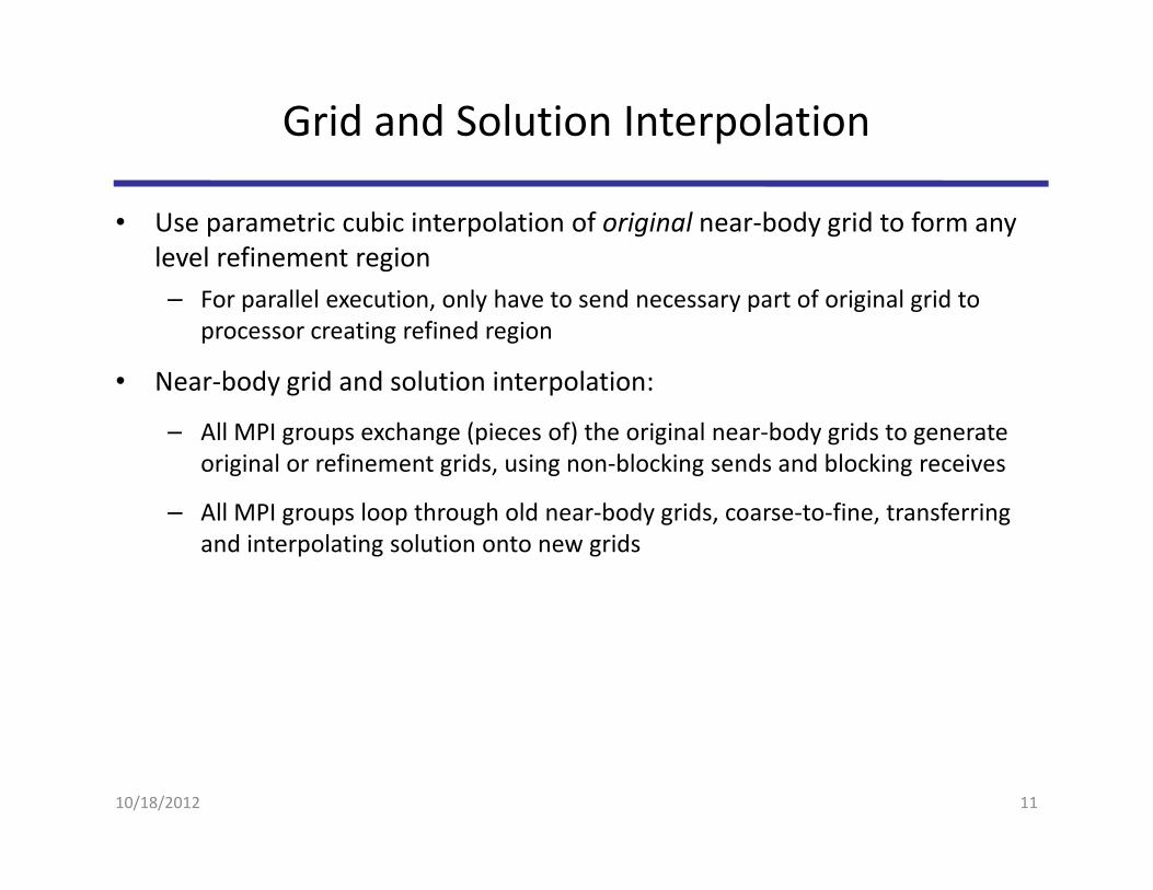
Grid and Solution Interpolation
• Use parametric cubic interpolation of original near-body grid to form any
level refinement region
– For parallel execution, only have to send necessary part of original grid to
processor creating refined region
• Near-body grid and solution interpolation:
– All MPI groups exchange (pieces of) the original near-body grids to generate
11
–
original or refinement grids, using non-blocking sends and blocking receives
– All MPI groups loop through old near-body grids, coarse-to-fine, transferring
and interpolating solution onto new grids
10/18/2012
Example Applications
• NACA 0012 airfoil
• 2D supersonic inlet
• Leading/trailing wing interaction
• Vortex generator on a flat plate
12
• Vortex generator on a flat plate
10/18/2012

• Refinement shows additional flow features, resolves pressure details
NACA 0012 Airfoil
Mach contours
Original 253x73 O-grid
Total grid size 18K points
4 levels of grid adaption
Total grid size 450K points
1310/18/2012
Flow conditions: Mach 0.55, alpha 8.34 deg, Re=9M/chord
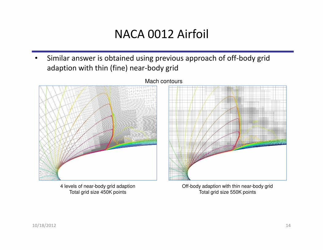
NACA 0012 Airfoil
• Similar answer is obtained using previous approach of off-body grid
adaption with thin (fine) near-body grid
Mach contours
1410/18/2012
Off-body adaption with thin near-body grid
Total grid size 550K points
4 levels of near-body grid adaption
Total grid size 450K points

• Grid refinement gives resolution of bounce in Cp due to lambda shock
NACA 0012 Airfoil
1510/18/2012
Mach contours with 4 levels of near-body grid adaption
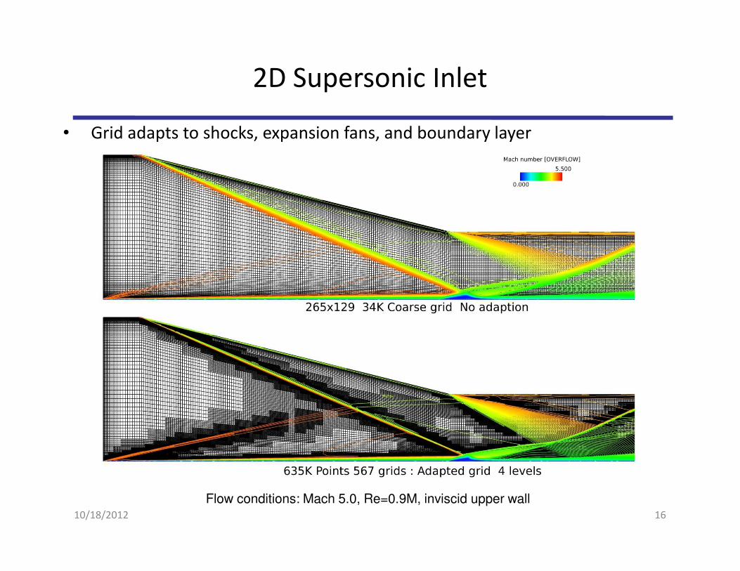
• Grid adapts to shocks, expansion fans, and boundary layer
2D Supersonic Inlet
1610/18/2012
Flow conditions: Mach 5.0, Re=0.9M, inviscid upper wall

• Visible details of shock/boundary layer interaction, allowing better evaluation of
turbulence model response to physics
2D Supersonic Inlet
1710/18/2012
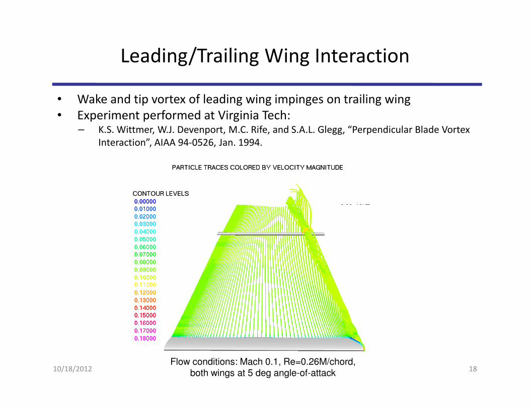
• Wake and tip vortex of leading wing impinges on trailing wing
• Experiment performed at Virginia Tech:– K.S. Wittmer, W.J. Devenport, M.C. Rife, and S.A.L. Glegg, “Perpendicular Blade Vortex
Interaction”, AIAA 94-0526, Jan. 1994.
Leading/Trailing Wing Interaction
1810/18/2012Flow conditions: Mach 0.1, Re=0.26M/chord,
both wings at 5 deg angle-of-attack
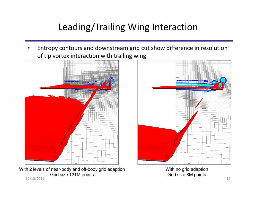
• Entropy contours and downstream grid cut show difference in resolution
of tip vortex interaction with trailing wing
Leading/Trailing Wing Interaction
1910/18/2012
With 2 levels of near-body and off-body grid adaptionGrid size 121M points
With no grid adaptionGrid size 8M points

• Original grid system included plate grid, box grid, and vortex generator grids
• Throw away box grid and let adaption resolve grid communication
Vortex Generator on a Flat Plate
Original surface grids
Without box grid
2010/18/2012
Adapted surface grids
Reference for original vortex generator analysis:B.G. Allan, C.-S. Yao, and J.C. Lin, “Numerical Simulationsof Vortex Generator Vanes and Jets on a Flat Plate,” AIAA 2002-3160, June 2002
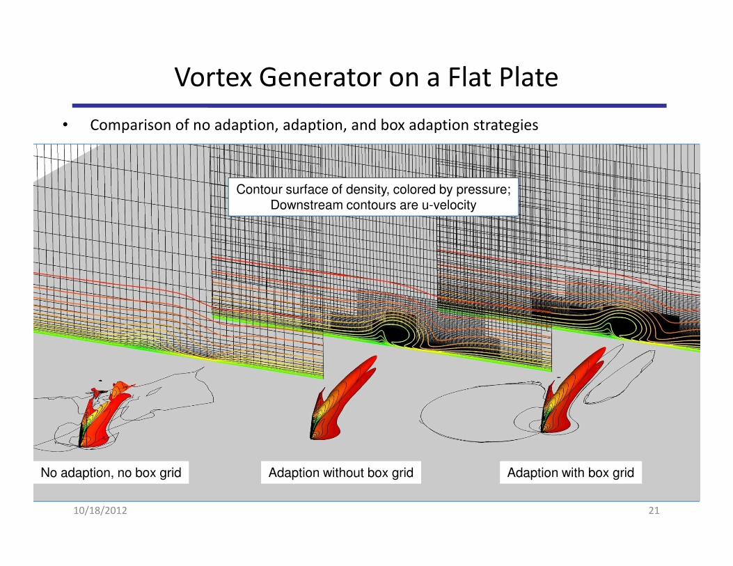
• Comparison of no adaption, adaption, and box adaption strategies
Vortex Generator on a Flat Plate
Contour surface of density, colored by pressure;Downstream contours are u-velocity
2110/18/2012
Adaption without box gridNo adaption, no box grid Adaption with box grid

Issues
• Limitations on original grid topology
• Parametric cubic interpolation for grid refinement
2210/18/2012
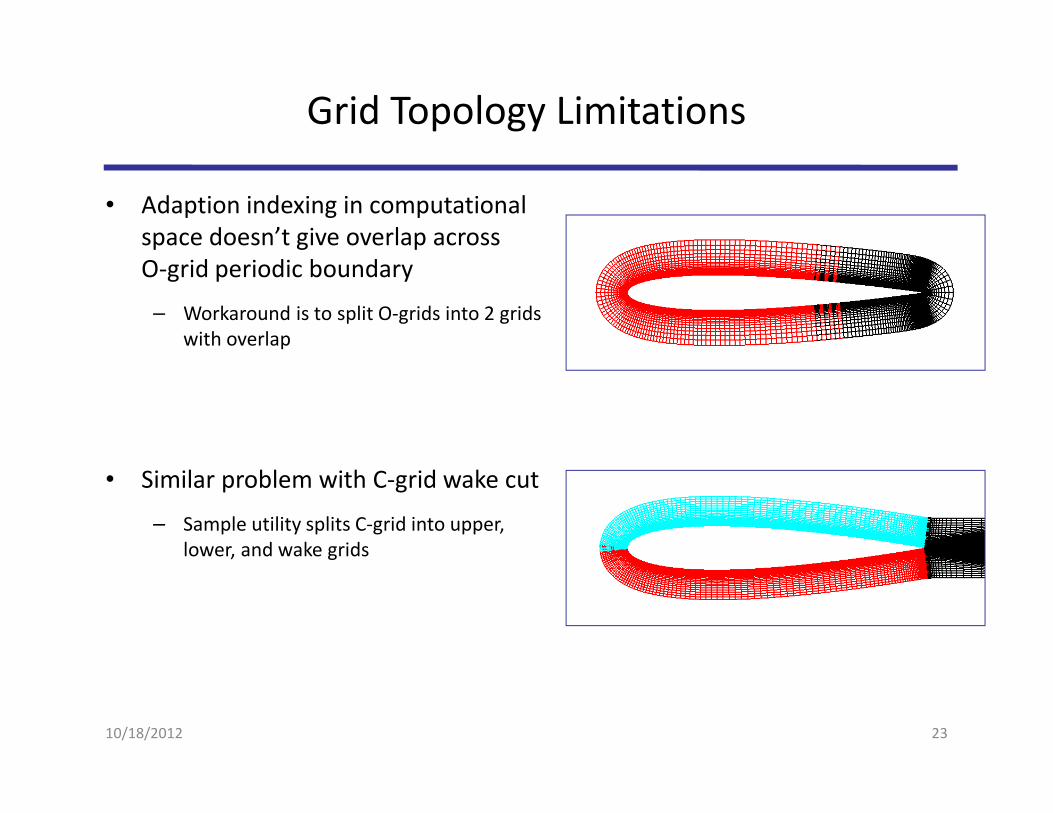
Grid Topology Limitations
• Adaption indexing in computational
space doesn’t give overlap across
O-grid periodic boundary
– Workaround is to split O-grids into 2 grids
with overlap
23
• Similar problem with C-grid wake cut
– Sample utility splits C-grid into upper,
lower, and wake grids
10/18/2012
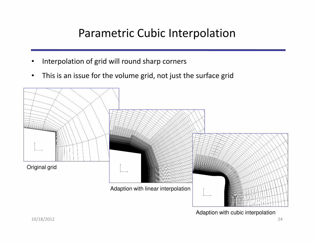
Parametric Cubic Interpolation
• Interpolation of grid will round sharp corners
• This is an issue for the volume grid, not just the surface grid
2410/18/2012
Original grid
Adaption with linear interpolation
Adaption with cubic interpolation

Summary and Future Work
Summary:
• A usable near-body grid adaption capability has been implemented and released
in OVERFLOW
• Adaption is parallelized and fast enough for time-accurate moving-body problems
Future Work:
• Better handling of volume grids that are not smooth
• Implement O-grid (and C-grid?) adaption without the user splitting the grid
25
• Implement O-grid (and C-grid?) adaption without the user splitting the grid
• Investigate the balance between near-body and off-body grids, with adaption
• Extend near-body adaption to work with grid systems assembled with Pegasus 5
• Implement some control on growth of grid system
10/18/2012