Embed Size (px)
Citation preview

80‐ENG‐D‐20 0‐23DEC15
InjectionMouldStandardsThepurposeofthisdocumentistoprovidetoolingsourceswithstandardsforquotingand
theconstructionofInjectionMouldsforABCGroupExteriorsBusinessUnit.

INJECTION MOULD STANDARDS
Page 1 of 20 80‐ENG‐D‐20 0‐23DEC15
© All contents are protected by copyright. The copyright for any material (in any form) created by ABC Group Inc. is reserved.
Any duplication or use of content other than for the purposes prescribed in this Manual or in any electronic or printed publications is not permitted without the written consent of ABC Group Inc.
This electronic edition of the Manual supersedes all other forms of the Manual.
INJECTION MOULD STANDARDS
Page 2 of 20 80‐ENG‐D‐20 0‐23DEC15
Table of Contents Abstract ........................................................................................................................................................ 3
Section 1: Introduction ................................................................................................................................. 4
Section 2: Mould Design .............................................................................................................................. 4
Section 3: Mould Delivery & Progress Reports ........................................................................................... 7
Section 4: Mould Sampling Requirements ................................................................................................... 7
Section 5: Mould Certification & Build Tolerance ...................................................................................... 7
Section 6: Mould Supplier Maintain Cost & Quality ................................................................................... 8
Section 7: Mould Identification .................................................................................................................... 8
Section 8: General Mould Construction ....................................................................................................... 9
Section 9: Mould Surface Finish ................................................................................................................ 10
Section 10: General Mould Steels & Components ..................................................................................... 10
Section 11: Runners & Gating ................................................................................................................... 11
Section 12: Hot Runner Manifolds / Hot Sprue Bushing ........................................................................... 11
Section 13: Inserts ...................................................................................................................................... 12
Section 14: Parting Line & Vents............................................................................................................... 12
Section 15: Mould Locks ........................................................................................................................... 13
Section 16: Waterlines ............................................................................................................................... 13
Section 17: Leader Pins .............................................................................................................................. 14
Section 18: Ejection ................................................................................................................................... 15
Section 19: Return Pins & Support Pillars ................................................................................................. 15
Section 20: Die Springs & Clamp Slots ..................................................................................................... 16
Section 21: Mould Lubrications ................................................................................................................. 16
Section 22: Slides ....................................................................................................................................... 16
Section 23: Lifters ...................................................................................................................................... 17
Section 24: Hydraulic Cylinders ................................................................................................................ 18
Section 25: Welding / Heat Treating .......................................................................................................... 19
Section 26: SPT .......................................................................................................................................... 19
Section 27: Shipping / Transportation ........................................................................................................ 19

INJECTION MOULD STANDARDS
Page 3 of 20 80‐ENG‐D‐20 0‐23DEC15
Abstract This Injection Mould Standard has been developed by ABC Group Exterior Business Unit to
document standard practices developed using lessons learned and best practices in the design
& builds of Injection Moulds.
The design of a good Injection Mould permits repeatable moulding of parts free of sink, read
through, deformation and other poor characteristics. Using this standard, ABC Group is able
to produce quality parts that conform to customer expectations and continue to receive
recognition as one of the most reputable suppliers in North America.
INJECTION MOULD STANDARDS
Page 4 of 20 80‐ENG‐D‐20 0‐23DEC15
Section 1: Introduction
1. The purpose of this document is to provide tooling sources with standards for quoting and
construction of injection moulds for ABC Group.
2. ABC Group values supplier’s opinion and encourages all tool sources to submit their
recommendations to improve the quality and effectiveness for moulds.
3. The intent of this document is not to include all possible requirements and therefore
consultation for specific customer standards or requirements with each new project is
necessary.
4. The information disclosed in this Mould Standard is considered privileged and confidential
material. Any disclosure, copying or distribution of these documents without ABC Group’s
authorization is prohibited. If any of the following pages are missing or unclear please
contact ABC Group’s Engineering Department.
Section 2: Mould Design
1. A series of design reviews are to be initiated in a timely manner by the tool source.
Participants should include personnel from the facility that will be involved in running the
tools.
a) Kick Off Meeting: Will be held in order to discuss any particular tool requirements
and to establish possible gate locations and gate type in order to proceed with mould
flow.
b) Preliminary Design Review: Establish general steel sizes and tool actions; Press
specifications will be provided by ABC Engineering.
c) Cooling Review: Cooling review of all mould components, core, cavity and any
actions that would require cooling.
d) Intermediate Design Review: Review of parting lines, actions, locks and seal offs.
e) Final Design Review: Capturing all input gathered from prior reviews.
Note: “OK –TO – TOOL” approval must be signed by ABC group Engineering and in some
cases, ABC’s customer. “OK –TO – TOOL” may be required during design stages depending on
job specific requirements.
INJECTION MOULD STANDARDS
Page 5 of 20 80‐ENG‐D‐20 0‐23DEC15
2. Mold Flow Analysis
i. All injection mold tools manufactured for ABC Group must have a Moldflow analysis study performed to simulate the flow of molten polymer inside the runner and mold system
ii. The purpose of Moldflow analysis is to help optimizing plastic part and injection mold designs, reduce potential part defects, and optimize the molding process setting
iii. Moldflow analysis simulates the injection molded polymer melt throughout the mold with data collected for interpretation
iv. The Moldflow program covers three levels: Bronze, Silver, and Gold. The selected level for analysis should be identified by Moldflow requester as per customer certification requirement
v. A series of meetings are to be initiated in a timely manner by the Moldflow Analyst to determine the best gating and runner systems and cavitation strategies. Meeting participants should include Tooling Specialist and Project Engineer/Program Manager and the personnel from the facility involved in running the tools, if necessary
vi. The Moldflow analysis study should be performed preferably by CAE Team within ABC Group and outsourced if necessary. The outsourced analysis must be approved by ABC Group prior to any steel order and cut
vii. Prior to Moldflow analysis the position of part inside the mold with respect to nozzle location must be known
viii. Material grade with required CRIMS/shrinkage data known as UDB file should be provided by the Moldflow requester
ix. In case the UDB file is not available efforts should be done to prepare the data through a recognized lab or resin should be switched to a grade with available UDB file
x. The Moldflow analysis should include fill, pack, ideal and actual cooling, warp analysis, and optimization process
xi. Filling: to help predict the flow of melted plastic and fill mold cavities uniformly; avoid short shots; and eliminate, minimize, or reposition weld lines and air traps
xii. Packing: optimize packing profiles and visualize magnitude and distribution of volumetric shrinkage to help minimize plastic part warpage and reduce defects such as sink marks
xiii. Injection pressure should not exceed 80% of machine rating without written authorization from ABC Group
xiv. Potential defects determined by Moldflow analysis should be addressed in the result presentation with recommendation on how to avoid those defects
xv. Moldflow analysis includes the following steps: xvi. Import the CAD data into the software: The acceptable formats are IGES,
STEP, and Parasolid xvii. Mesh the model: In order to analyze fluid flows, flow domains are split
into smaller subdomains (made up of geometric primitives like hexahedra
INJECTION MOULD STANDARDS
Page 6 of 20 80‐ENG‐D‐20 0‐23DEC15
and tetrahedral in 3D and quadrilaterals and triangles in 2D) that are collectively known as meshing.
xviii. Examine the mesh deficiencies e.g. overlaps, discontinuity, and dimensional inconsistencies
xix. Start the analysis xx. Perform process setting and part geometry upgrades and re-analyze as
many iterations as required to improve processing or molding conditions xxi. Deliverables:
xxii. Preliminary report: Gate locations, runner system, part modification proposals, knit line locations, cooling design modifications and GMW16355 outputs will be submitted as needed throughout the project
xxiii. Final report: A comprehensive final report will be issued at the end of the project which will include the following:
xxiv. Summary of the objectives achieved xxv. Part design, mold design, and processing setup/recommendations
xxvi. Mold information xxvii. Detailed results for Fill, Pack, Cool, and Warpage
xxviii. Where outside vendors are engaged a copy of the final Analysis input/output files is to be forwarded to ABC Tech Centre CAE team for databanking
xxix. Sourcing: xxx. All quotes and purchases orders to be released through ABC Group Tech
Centre CAE Service team. CAE Service team will assist PM/PE/ME with technical aspects of the process and achieving timing requirements.
xxxi. A DCS is to be issued into the MyABC Parts database application to
support scheduling and databanking
3. It is the responsibility of the tool source to update mould design when incorporating
engineering changes regardless of whether the mould is under construction or completed.
4. A complete bill of material is to be provided specifying original manufacturer, part number
and origin of purchase.
5. Original hot runner supplier designs (2D&3D) & BOMs are to be provided to ABC.
6. Approval of mould design from ABC does not relieve tool vendor of responsibility of
delivering a tool that produces a dimensionally correct part within the quoted cycle time.
7. It is expected that during the tool design stages, the tool maker will identify and notify ABC
if there are any part features (rib to wall ratios, minimal draft, etc.) that could affect the
performance of the tool or produce an unacceptable part.
8. All CAD data, feasibility reports, mould flows and tooling aids are to be considered
intellectual property of ABC and shall made available to ABC at any time. Upon completion
INJECTION MOULD STANDARDS
Page 7 of 20 80‐ENG‐D‐20 0‐23DEC15
of mould, tool source is to provide ABC all of the above mentioned items. Mould designs are
to be provided in their native software format as well as a copy in .STP format.
9. All moulded parts are to have identification:
a) Part number.
b) Material type.
c) Date wheel/grid.
d) Any other identification required will be provided by ABC Engineering.
Section 3: Mould Delivery & Progress Reports
1. Established delivery dates must be held. This is for both new moulds and engineering
changes on existing moulds. Failure to meet this date may result in down rating. Please note,
the effect of engineering changes that occur during a new build will be factored into the final
due date.
2. A tool timeline is to be provided at kick off. Tool progress reports maybe requested at any
time during the build. Frequency of progress reports will be job specific.
Section 4: Mould Sampling Requirements
1. Sampling requirements are a minimum of 3 trials at an agreed upon trial facility. Quantity of
samples is 150 pieces per trial but requirements will be job specific and will be clarified in
original RFQ.
2. It is the tool shop’s responsibility to sample the mould as many times as necessary to prove
out the mechanical and dimensional integrity of the mould, including any unacceptable flash,
mismatch of parting lines or surface finishes.
3. One day plant support (toolmaker at ABC facility) at an agreed upon time is to be provided
by tool source for each tool.
Section 5: Mould Certification & Build Tolerance
1. Prior to first shot, the mould is to be CMM checked to assure that the mould has been cut to
design data, “A” surface and critical features are expected to be +/- .002″.
INJECTION MOULD STANDARDS
Page 8 of 20 80‐ENG‐D‐20 0‐23DEC15
Section 6: Mould Supplier Maintain Cost & Quality
1. Tool supplier must maintain cost and delivery as quoted and authorized by purchase order.
Any deviation from approved P.O. must be approved by ABC Group Engineering before
additional work may proceed.
2. Tool supplier is responsible for cost, timing, quality and adherence to ABC group standards
for any subcontracted services and or materials. ABC Group Engineering is to be advised if
any tooling is to be outsourced.
3. Tool supplier is responsible to provide a mould that produces a visually approved part that is
to print. Any deviation from part to print must be in writing and kept as a permanent part of
the mould construction records.
4. Tool supplier is responsible for all necessary transportation, disassembly, cleaning re-
assembly etc. required for final surface treatment (hardening texture, vapor blast, plating,
etc.) after dimensional approval.
5. Tooling breakdown sheet will be provided and must be filled by Tool Supplier. (Reference:
ABC Tool Cost Breakdown Worksheet)
6. Except for normal wear items, mould warranty will last the life of the program.
Section 7: Mould Identification
1. Customer Mould Asset Identification
a) Method of identifying mould with customer asset identification will be provided by
ABC Engineering.
b) Note: Customer mould asset identification and Mould I.D. plate are both required.
2. All tools are to have a Mould I.D. plate permanently fixed to operator side of the tool in an
agreed upon location. Mould I.D. plate will list the following:
a) Part Name.
b) Part Number.
c) Mould Number.
d) Mould Maker.
e) Number of Cavities.
f) Overall Mould Dimensions and Weight.
g) Ejector Stroke Maximum.
INJECTION MOULD STANDARDS
Page 9 of 20 80‐ENG‐D‐20 0‐23DEC15
h) Maximum stroke for opened mould (if required).
3. “Top of Mould” is to be stamped in 1" high letters.
4. Components such as slides, lifters, gibs and wear plates are to be permanently marked so as
the tool can be easily disassembled and assembled in the same way that the tool was
delivered.
5. All cores are to be engraved with identification such as part number, date grid/wheel,
material, etc., this will be established in RFQ.
Section 8: General Mould Construction
1. Tools must have limit switches for ejection or any actions that need to be tied into the
machine sequence. Large slides require micro switches for both in and out positions.
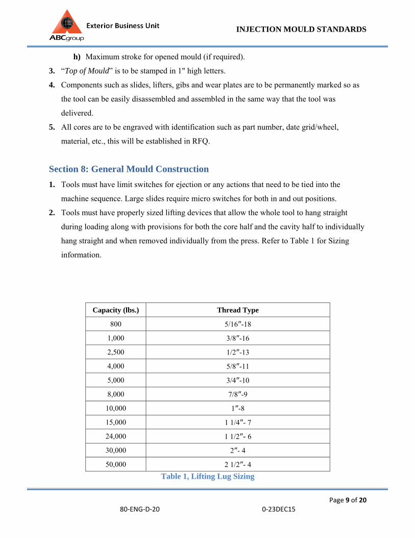
2. Tools must have properly sized lifting devices that allow the whole tool to hang straight
during loading along with provisions for both the core half and the cavity half to individually
hang straight and when removed individually from the press. Refer to Table 1 for Sizing
information.
Capacity (lbs.) Thread Type
800 5/16″-18
1,000 3/8″-16
2,500 1/2″-13
4,000 5/8″-11
5,000 3/4″-10
8,000 7/8″-9
10,000 1″-8
15,000 1 1/4″- 7
24,000 1 1/2″- 6
30,000 2″- 4
50,000 2 1/2″- 4
Table 1, Lifting Lug Sizing
INJECTION MOULD STANDARDS
Page 10 of 20 80‐ENG‐D‐20 0‐23DEC15
3. Tools that have components protruding beyond the clamp plates are to have protection in
order to prevent damage to tool while loading or placing on the floor. In cases where there
are items protruding from the bottom of the mould, feet must be installed on both core and
cavity so that individual halves of the tool can safely stand alone.
4. Water and hydraulic lines are to be connected from the non-operator side of tool.
5. Components weighing more than 25 lbs. must have their own lifting devices.
6. Electrical connections for hot manifold are to be placed on top of the tool.
7. Tools running in a press greater than 500 ton must have hydraulic ejection with flow
dividers.
8. Safety straps are to be located on opposite sides of the mould and painted yellow for high
visibility.
9. All tools are to have shot counters.
Section 9: Mould Surface Finish
1. All graining requirements and associated costs such as preparation and shipping are the
responsibility of the tool source and are to be included in the mould build. Grain source will
be specified by ABC Group Engineering. No graining can be applied without written
approval.
2. Core moulding surfaces are to have a surface finish of a minimum of 320 stone unless
otherwise specified.
3. Cavity surface finish for painted parts is to be #600 paper.
4. All ribs are to be draw polished.
Section 10: General Mould Steels & Components
1. All mould components are to be standard “off – the – shelf” components purchased
preferably from DME. Custom made items such as Sprue bushings and locating rings are not
permitted. The tool shop will need to get written approval if custom components are required.
INJECTION MOULD STANDARDS
Page 11 of 20 80‐ENG‐D‐20 0‐23DEC15
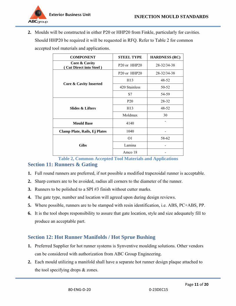
2. Moulds will be constructed in either P20 or HHP20 from Finkle, particularly for cavities.
Should HHP20 be required it will be requested in RFQ. Refer to Table 2 for common
accepted tool materials and applications.
COMPONENT STEEL TYPE HARDNESS (RC)
Core & Cavity ( Cut Direct into Steel )
P20 or HHP20 28-32/34-38
Core & Cavity Inserted
P20 or HHP20 28-32/34-38
H13 48-52
420 Stainless 50-52
S7 54-59
Slides & Lifters
P20 28-32
H13 48-52
Moldmax 30
Mould Base 4140 -
Clamp Plate, Rails, Ej Plates 1040 -
Gibs
O1 58-62
Lamina -
Amco 18 -
Table 2, Common Accepted Tool Materials and Applications Section 11: Runners & Gating
1. Full round runners are preferred, if not possible a modified trapezoidal runner is acceptable.
2. Sharp corners are to be avoided, radius all corners to the diameter of the runner.
3. Runners to be polished to a SPI #3 finish without cutter marks.
4. The gate type, number and location will agreed upon during design reviews.
5. Where possible, runners are to be stamped with resin identification, i.e. ABS, PC+ABS, PP.
6. It is the tool shops responsibility to assure that gate location, style and size adequately fill to
produce an acceptable part.
Section 12: Hot Runner Manifolds / Hot Sprue Bushing
1. Preferred Supplier for hot runner systems is Synventive moulding solutions. Other vendors
can be considered with authorization from ABC Group Engineering.
2. Each mould utilizing a manifold shall have a separate hot runner design plaque attached to
the tool specifying drops & zones.
INJECTION MOULD STANDARDS
Page 12 of 20 80‐ENG‐D‐20 0‐23DEC15
3. Each zone is not to exceed 15 amps.
4. Electrical connectors from the manifold to the controller are as follows:
a) Thermocouple Connectors DME MTC-12-G.
b) Power Connectors DME PIC-12-G.
5. For single zone system (Hot Sprue Bushing) DME CKPTIC-1 is to be used.
6. All connectors are to be either on “top of mould” or opposite to operator’s side on tool.
Connectors are to be recessed into tool or mounted on electrical boxes.
7. All manifold and drops are to be controlled using type “J” thermal couples. Each heat zone is
to have a thermal couple. Thermal couples are to be numbered to correspond to heater zone
numbers.
8. All wiring is to be protected from damage during handling.
Section 13: Inserts
1. All inserts are to have knock out holes or “jack” screw holes located in opposite corners.
2. In the case of interchangeable inserts, every attempt shall be made to ensure they are
interchangeable from the mould surface, to eliminate the pulling of the mould from the press
and dis-assembly of the mould.
3. Inserts must be used for all deep ribs (over 1″), and provisions should be made for venting
behind insert.
4. All large inserts are to have their own cooling circuits. When inserts are too small to have
cooling circuits, high thermal conductivity, beryllium free materials can be considered to
assist in cooling. Use of these materials for any cooling application should be discussed and
approved during mould design reviews.
5. Welding of inserts into the mould base is not acceptable.
Section 14: Parting Line & Vents
1. As a general guide line the following should be observed:

INJECTION MOULD STANDARDS
Page 13 of 20 80‐ENG‐D‐20 0‐23DEC15
a) Parting line 100% contact for a minimum of 1.0″ around the part perimeter.
b) 100% contact of approximately 6 in2 around the leader pins.
c) All other areas are to be relieved by 0.030″.
d) Parting line vents should be typically every 2″, ½″ wide and vented to atmosphere,
vent the depth specific to resin being used.
Section 15: Mould Locks
1. The height of the taper locks is to have height to width ratio of a minimum of 1:1.
2. Tools must have locking in 4 directions.
3. If mould locks are on higher seal off angles than the part seal offs, straight locks inserted die
liners must be made of high resistance materials to minimize wear, and should be installed at
zero degrees or one degree to compensate for mould/press sag, and protect/maintain small
seal off angles.
Section 16: Waterlines
1. Recommended waterline diameter is as follows:
75 ton – 0.21″ (7/32″)
250 – 500 ton – 0.25″ – 0.375″ (1/4″ – 3/8″)
500 – 700 ton – 0.687″ (11/16″)
1000 – & up – 0.875″ (7/8″)
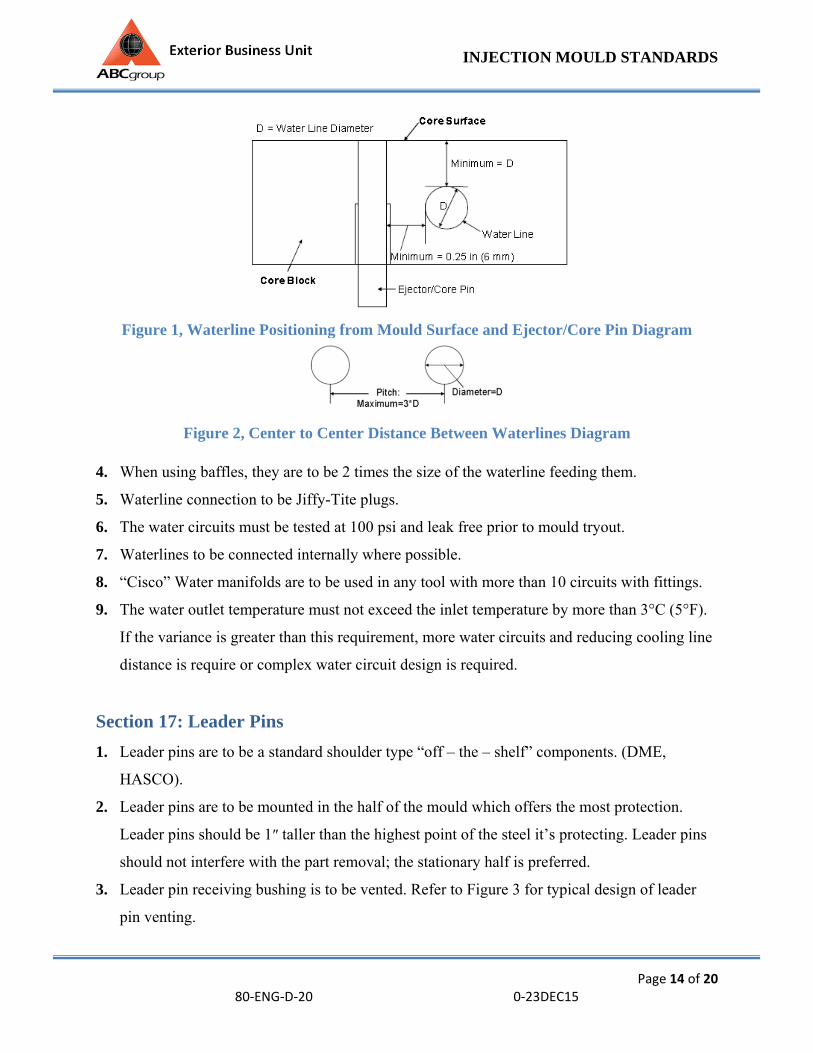
2. Waterlines are to be located to produce even cooling throughout the part in both core and
cavity. Waterlines are generally to be placed within 3 times the diameter of each other and no
closer than 1 times diameter from the surface following part contour. Refer to Figure 1 & 2
for waterline position diagrams.
3. Water inlets and outlets shall be stamped with ½″ high letters on the side on the tool. All
water connections to be opposite to operator side or the bottom of the tool.
INJECTION MOULD STANDARDS
Page 14 of 20 80‐ENG‐D‐20 0‐23DEC15
Figure 1, Waterline Positioning from Mould Surface and Ejector/Core Pin Diagram
Figure 2, Center to Center Distance Between Waterlines Diagram
4. When using baffles, they are to be 2 times the size of the waterline feeding them.
5. Waterline connection to be Jiffy-Tite plugs.
6. The water circuits must be tested at 100 psi and leak free prior to mould tryout.
7. Waterlines to be connected internally where possible.
8. “Cisco” Water manifolds are to be used in any tool with more than 10 circuits with fittings.
9. The water outlet temperature must not exceed the inlet temperature by more than 3°C (5°F).
If the variance is greater than this requirement, more water circuits and reducing cooling line
distance is require or complex water circuit design is required.
Section 17: Leader Pins
1. Leader pins are to be a standard shoulder type “off – the – shelf” components. (DME,
HASCO).
2. Leader pins are to be mounted in the half of the mould which offers the most protection.
Leader pins should be 1″ taller than the highest point of the steel it’s protecting. Leader pins
should not interfere with the part removal; the stationary half is preferred.
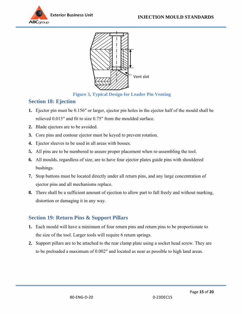
3. Leader pin receiving bushing is to be vented. Refer to Figure 3 for typical design of leader
pin venting.
INJECTION MOULD STANDARDS
Page 15 of 20 80‐ENG‐D‐20 0‐23DEC15
Section 18: Ejection
1. Ejector pin must be 0.156″ or larger, ejector pin holes in the ejector half of the mould shall be
relieved 0.015″ and fit to size 0.75″ from the moulded surface.
2. Blade ejectors are to be avoided.
3. Core pins and contour ejector must be keyed to prevent rotation.
4. Ejector sleeves to be used in all areas with bosses.
5. All pins are to be numbered to assure proper placement when re-assembling the tool.
6. All moulds, regardless of size, are to have four ejector plates guide pins with shouldered
bushings.
7. Stop buttons must be located directly under all return pins, and any large concentration of
ejector pins and all mechanisms replace.
8. There shall be a sufficient amount of ejection to allow part to fall freely and without marking,
distortion or damaging it in any way.
Section 19: Return Pins & Support Pillars
1. Each mould will have a minimum of four return pins and return pins to be proportionate to
the size of the tool. Larger tools will require 6 return springs.
2. Support pillars are to be attached to the rear clamp plate using a socket head screw. They are
to be preloaded a maximum of 0.002″ and located as near as possible to high land areas.
Vent slot
Figure 3, Typical Design for Leader Pin Venting
INJECTION MOULD STANDARDS
Page 16 of 20 80‐ENG‐D‐20 0‐23DEC15
Section 20: Die Springs & Clamp Slots
1. Springs are to be medium compression springs with a maximum deflection without
exceeding 30% of the total spring length.
2. Clamp slots must be a minimum of 1.375″ from the platen surface and the size shall be 1.25″
deep x 1.25″ high.
3. Clamping to be designed to clear any external components on mould. Clamping design is to
be reviewed in design stage with ABC Engineering.
4. Any special clamp requirements such as QMC (Quick Mould Change Systems) will be
requested on RFQ.
Section 21: Mould Lubrications
1. Every mould is to have external lubrication fittings for all sliding components, except ejector
pins and lifter rod bushings. Grease grooves will be in the stationary member of the sliding
components and should not be uncovered by the sliding component at any time.
2. Each fitting will supply grease at one location only, flexible lines are permitted when internal
lines are not possible.
3. Lubricants containing Teflon, Silicone or similar type are not permitted.
Section 22: Slides
1. When slides are necessary, they are to be mechanically driven whenever possible.
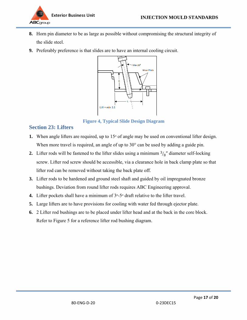
2. A maximum of 20° is to be used on horn pins. Slides that require greater travel may be
driven by a hydraulic cylinder. When cylinders are used the slide is to be locked in position
by a heel block. Refer to Figure 4 for a typical slide design diagram.
3. All slides must utilize a bottom O1 or Lamina wear plates Refer to Figure 4.
4. When using O1, all wear surfaces and gibs are to have grease grooves and provisions for
lubrication without disassembly of mould.
5. Stop blocks, chisel plungers or both will be required to hold the slide in its proper location.
6. Spring loaded ball plungers are not acceptable.
7. Slides that travel in a vertical direction must have slide retainers.
INJECTION MOULD STANDARDS
Page 17 of 20 80‐ENG‐D‐20 0‐23DEC15
8. Horn pin diameter to be as large as possible without compromising the structural integrity of
the slide steel.
9. Preferably preference is that slides are to have an internal cooling circuit.
Figure 4, Typical Slide Design Diagram Section 23: Lifters
1. When angle lifters are required, up to 15ᵒ of angle may be used on conventional lifter design.
When more travel is required, an angle of up to 30° can be used by adding a guide pin.
2. Lifter rods will be fastened to the lifter slides using a minimum 3 8″ diameter self-locking
screw. Lifter rod screw should be accessible, via a clearance hole in back clamp plate so that
lifter rod can be removed without taking the back plate off.
3. Lifter rods to be hardened and ground steel shaft and guided by oil impregnated bronze
bushings. Deviation from round lifter rods requires ABC Engineering approval.
4. Lifter pockets shall have a minimum of 3ᵒ-5ᵒ draft relative to the lifter travel.
5. Large lifters are to have provisions for cooling with water fed through ejector plate.
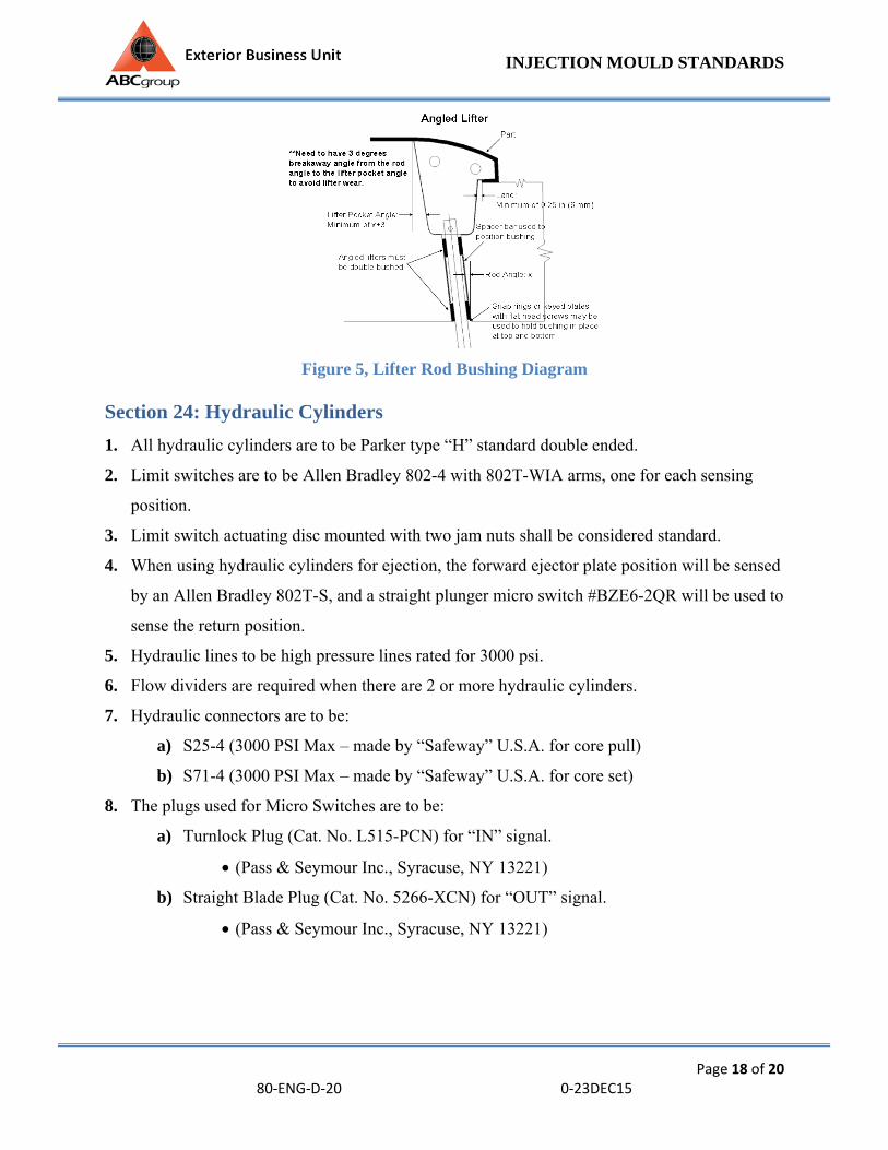
6. 2 Lifter rod bushings are to be placed under lifter head and at the back in the core block.
Refer to Figure 5 for a reference lifter rod bushing diagram.
INJECTION MOULD STANDARDS
Page 18 of 20 80‐ENG‐D‐20 0‐23DEC15
Figure 5, Lifter Rod Bushing Diagram
Section 24: Hydraulic Cylinders
1. All hydraulic cylinders are to be Parker type “H” standard double ended.
2. Limit switches are to be Allen Bradley 802-4 with 802T-WIA arms, one for each sensing
position.
3. Limit switch actuating disc mounted with two jam nuts shall be considered standard.
4. When using hydraulic cylinders for ejection, the forward ejector plate position will be sensed
by an Allen Bradley 802T-S, and a straight plunger micro switch #BZE6-2QR will be used to
sense the return position.
5. Hydraulic lines to be high pressure lines rated for 3000 psi.
6. Flow dividers are required when there are 2 or more hydraulic cylinders.
7. Hydraulic connectors are to be:
a) S25-4 (3000 PSI Max – made by “Safeway” U.S.A. for core pull)
b) S71-4 (3000 PSI Max – made by “Safeway” U.S.A. for core set)
8. The plugs used for Micro Switches are to be:
a) Turnlock Plug (Cat. No. L515-PCN) for “IN” signal.
(Pass & Seymour Inc., Syracuse, NY 13221)
b) Straight Blade Plug (Cat. No. 5266-XCN) for “OUT” signal.
(Pass & Seymour Inc., Syracuse, NY 13221)
INJECTION MOULD STANDARDS
Page 19 of 20 80‐ENG‐D‐20 0‐23DEC15
Section 25: Welding / Heat Treating
1. Welding on moulding faces of cavity, core, slides, lifters, etc. is prohibited without written
permission from ABC group Engineering.
2. Where welding is required and approved, all welding is to be completed by an approved
welding source, color matched to follow steel supplier’s recommended procedures. Welding
maps and welding supplier identification to be provided to ABC Engineering.
3. When heat treating is required, mould supplier must keep heat treat records. These are to be
kept as permanent records and must include heat treat supplier hardness tests etc.
Section 26: SPT 1. Tools to be manufactured for a SPT process will be requested in RFQ.
2. Tools manufactured for a SPT process require the following:
a. O-Ring seal around the perimeter of parting line outside the vents.
b. Ejector pin must have seal packs.
c. Location of gas channels and venting will be reviewed during design stages.
Section 27: Shipping / Transportation
1. All Injection Moulds must be completely protected from the environment when being
shipped.
2. All Injection Moulds must be completely secured to avoid damage during shipping.
3. ABC will not accept any Injection Mould if it is delivered with damage or defect.

INJECTION MOULD STANDARDS
Page 20 of 20 80‐ENG‐D‐20 0‐23DEC15
The information in this Manual is subject to change without notice, revision levels and history is available for identification of latest version.
Revision Level Date Revised By Approved By Changes Made
0 1/19/15 Peter Bollmann
Ageth WicknesvaranJohn Sudak Initial Release