Embed Size (px)
Citation preview

INL/EXT-16-39808 Revision 0
Light Water Reactor Sustainability Program
Design Guidance for Computer-Based Procedures for Field Workers
September 2016
U.S. Department of Energy
Office of Nuclear Energy
DISCLAIMER This information was prepared as an account of work sponsored by an
agency of the U.S. Government. Neither the U.S. Government nor any agency thereof, nor any of their employees, makes any warranty, expressed or implied, or assumes any legal liability or responsibility for the accuracy, completeness, or usefulness, of any information, apparatus, product, or process disclosed, or represents that its use would not infringe privately owned rights. References herein to any specific commercial product, process, or service by trade name, trade mark, manufacturer, or otherwise, does not necessarily constitute or imply its endorsement, recommendation, or favoring by the U.S. Government or any agency thereof. The views and opinions of authors expressed herein do not necessarily state or reflect those of the U.S. Government or any agency thereof.
INL/EXT-39808 Revision 0
Design Guidance for Computer-Based Procedures for Field Workers
Johanna Oxstrand Katya Le Blanc
Aaron Bly
September 2016
Prepared for the U.S. Department of Energy Office of Nuclear Energy

iii
SUMMARY The paper-based procedures currently used for nearly all activities in the
commercial nuclear power industry have a long history of ensuring safe operation of the plants. However, there is potential to greatly increase efficiency and safety by improving how the human interacts with the procedures, which can be achieved through the use of computer-based procedures (CBPs). A CBP system offers a vast variety of improvements, such as context driven job aids, integrated human performance tools and dynamic step presentation.
The main purpose of the CBP research effort conducted at the Idaho National Laboratory was to provide design guidance to the nuclear industry to be used by both utilities and vendors. After studying existing design guidance for CBP systems, the researchers concluded that the majority of the existing guidance is intended for control room CBP systems, and does not necessarily address the challenges of designing CBP systems for instructions carried out in the field. Further, the guidance is often presented on a high level, which leaves the designer to interpret what is meant by the guidance and how to specifically implement it. The authors developed this design guidance to provide guidance specifically tailored to instructions that are carried out in the field based.
The high level design requirements are discussed in the design guidance document are;
1. Provide Context Sensitive Information Everywhere Possible
2. Support all Expected Task Flow Characteristics
3. Support Expected Level of Flexibility in Performing Task
4. Guide Worker Through Logical Sequence of the Procedure
5. Provide Information Needed to Control Path Through the Procedure
6. Provide Computerized Support Where Appropriate and Possible
7. Include Functionality That Improve Communication
8. Provide a Method to Review and Save Records
The design guidance provides several specific examples of how to implement each of the high level requirements and provides illustrations and explanations of the observed benefits of the concepts.
iv
ACKNOWLEDGEMENTS The authors would like to express special gratitude to the following people
for their collaboration and support of this research effort:
Thomas Waicosky, Catawba Nuclear Station, for supporting and hosting the laboratory evaluation study at Catawba’s flowloop in 2012 and a field study 2013.
Michael Grigsby, Palo Verde Nuclear Generating Station, for being the Palo Verde Management Sponsor for the research effort. Carlos Williams, Regina (Gina) Cunningham, and Christopher Kartes, and John Triolo, Palo Verde Nuclear Generating Station, for all their support of preparing and hosting the evaluation studies in 2012 and 2014.
Bruce Gordon, Jarad Ping, and David Delong, Palo Verde Nuclear Generating Station, for their support in the process to expand the INL computer-based procedure system to handle maintenance work orders and for all their support to plan and conduct the field validation study in 2014.
Dean Overland, K.R. Thompson, Adam Lyman, and Nicola Gaudiuso, Diablo Canyon Power Plant, for hosting a field study in 2015.`
James Flowers and Amy Houston (Southern Nuclear Company), and Tim Neal, Teresa Moore, Tracy Quick, and Toni Buxton (Plant Vogtle) for hosting a field study in 2015.
John Hernandez and Lorenzo Slay, Palo Verde Nuclear Generating Station, for supporting and hosting a computer-based procedures for plant modifications pilot in 2016.
The research team wants to extend its gratitude to all the participants and others involved in the successful execution of all the evaluation studies and field studies. The feedback you provided over the years have been highly valuable to the effort.
In addition, the authors would like to recognize and thank all the members of the Nuclear Electronic Work Packages – Enterprise Requirements initiative: Ameren, Arizona Public Service, Dominion, Duke Energy, Energy Northwest, Exelon Nuclear, First Energy, NextEra, Pacific Gas & Electric, SCANA, South Texas Project, Southern Nuclear, Talen Energy, Tennessee Valley Authority, Xcel Energy, Électricité de France, EDF Energy, Electric Power Research Institute, Institute for Energy Technology, Idaho National Laboratory, Institute of Nuclear Power Operations, Los Alamos National Laboratory, Savannah River National Laboratory, ATR Inc., BWX Technologies, Inc., Curtiss Wright, DataGlance, DevonWay, ErgoSix, Nuclear Energy Consultants, NextAxiom, Rolls Royce, Westinghouse, Accenture, and ScottMadden. The authors extend a special thank you to the Nuclear Information Technology Strategic Leadership Group, the Procedure Writers Association, and the Nuclear Information and Records Management Association representatives in NEWPER.
This report was made possible through funding by the U.S. DOE Light Water Reactor Sustainability Program.
v
CONTENTS
SUMMARY ................................................................................................................................................. iii
ACKNOWLEDGEMENTS ......................................................................................................................... iv
ACRONYMS ............................................................................................................................................... ix
1. INTRODUCTION .............................................................................................................................. 1 1.1 Computer-Based Procedures for Field Workers Research ....................................................... 2
1.1.1 Characterization of Procedure Usage .......................................................................... 2 1.1.2 Model Development and Identification of Requirements for CBPs ........................... 2 1.1.3 Evaluation Studies....................................................................................................... 3
1.2 CBP Taxonomies ..................................................................................................................... 4 1.2.1 IEEE 1786 ................................................................................................................... 5 1.2.2 EPRI – Smart Documents ........................................................................................... 6 1.2.3 NEWPER – Smart Documents ................................................................................... 7
1.3 Design Guidance Summary...................................................................................................... 8
2. DESIGN REQUIREMENTS ............................................................................................................ 10 2.1 Provide Context Sensitive Information Everywhere Possible ............................................... 10
2.1.1 Context Sensitive Information – Equipment State .................................................... 10 2.1.2 Context Sensitive Information – Expected As Found State ...................................... 12 2.1.3 Context Sensitive Information – As Left State ......................................................... 13 2.1.4 Context Sensitive Information – Step Instructions ................................................... 15 2.1.5 Context Sensitive Information – Notes and Cautions ............................................... 17 2.1.6 Context Sensitive Information – Decision Points and Branching ............................. 17
2.2 Support All Expected Task Flow Characteristics .................................................................. 19 2.2.1 Task Flow Characteristics – Conditional Steps ........................................................ 21 2.2.2 Task Flow Characteristics – Multiple Action Steps .................................................. 22 2.2.3 Task Flow Characteristics – Continuously Applicable Steps ................................... 26 2.2.4 Task Flow Characteristics – Peer-Checking, Concurrent and Independent
Verification ............................................................................................................... 28 2.2.5 Task Flow Characteristics – Placekeeping ................................................................ 28 2.2.6 Task Flow Characteristics – Notes, Cautions, and Warnings ................................... 29 2.2.7 Task Flow Characteristics – Supplemental Information and Attachments ............... 29 2.2.8 Task Flow Characteristics – Branching Step ............................................................ 31 2.2.9 Task Flow Characteristics – Hold Points .................................................................. 31 2.2.10 Task Flow Characteristics – Hierarchical Step Structure .......................................... 32 2.2.11 Task Flow Characteristics – Procedure Specific Information ................................... 32
2.3 Support Expected Level of Flexibility in Performing Task ................................................... 34 2.3.1 Flexibility – Navigation Within the Procedure ......................................................... 34 2.3.2 Flexibility – Ability to Undo an Unintended or Incorrect Action ............................. 34 2.3.3 Flexibility – Deviation from Step Sequence ............................................................. 35 2.3.4 Flexibility – Backup Methods for Currently Unavailable Functions ........................ 35
2.4 Guide Worker through Logical Sequence of the Procedure .................................................. 36 2.4.1 Simplified Step Logic – Conditional Statement ........................................................ 36 2.4.2 Simplified Step Logic – Nested Conditional Statement............................................ 38 2.4.3 Simplified Step Logic – Decision Based On Previous Input .................................... 38
vi
2.4.4 Simplified Step Logic – Automatic Identification of Not Applicable Steps ............. 39 2.5 Provide Information Needed to Control Path through the Procedure .................................... 40
2.5.1 Worker In-The-Loop – Decision Points and Branches ............................................. 40 2.5.2 Worker In-The-Loop – Revision of Incorrect Input or Decision .............................. 40
2.6 Provide Computerized Support Where Appropriate and Possible ......................................... 42 2.6.1 Computerized Support – Calculations Based on Manual Input ................................ 43 2.6.2 Computerized Support – Calculations When the Necessary Information is
Available ................................................................................................................... 44 2.6.3 Computerized Support – Branching .......................................................................... 44 2.6.4 Computerized Support – Correct Component Verification ....................................... 44 2.6.5 Computerized Support – Automatically Validate User Input ................................... 45 2.6.6 Computerized Support – Alert Users When Procedure Steps or Conditions
are at Risk to be Violated .......................................................................................... 45 2.6.7 Computerized Support – Automatically Populate Relevant Previous Log
Information ............................................................................................................... 46 2.6.8 Computerized Support – Automatically Populate Future Steps and/or Data
Sheets ........................................................................................................................ 47 2.7 Include Functionality that Improves Communication ............................................................ 49
2.7.1 Communication – Shift Turnover ............................................................................. 49 2.7.2 Communication – Field Worker and Supervisor ...................................................... 49 2.7.3 Communication – Control Room Operators and Field Worker ................................ 50
2.8 Provide a Method to Review and Save Records .................................................................... 51 2.8.1 Records – Paper Archives ......................................................................................... 51 2.8.2 Records – Electronic Archives .................................................................................. 51
3. REFERENCES ................................................................................................................................. 52
Appendix A Model of Procedure Usage .................................................................................................... 53
Appendix B Minimum Requirements for Computer-Based Procedures .................................................... 55
FIGURES Figure 1. Field workers participating in the evaluation and field studies. .................................................... 4
Figure 2. EPRI Smart Document Taxonomy. ............................................................................................... 7
Figure 3. NEWPER Smart Document Taxonomy. ....................................................................................... 8
Figure 4. Example of desired equipment state. ........................................................................................... 11
Figure 5. Example of reference image. ....................................................................................................... 12
Figure 6. Example of expected as found information. ................................................................................ 13
Figure 7. Example of as left information. ................................................................................................... 14
Figure 8. Example of previous log information. ......................................................................................... 15
Figure 9. Detailed information about actions in step. ................................................................................. 16
Figure 10. Examples of context sensitive information in the step. ............................................................. 16
Figure 11. Example of a caution. ................................................................................................................ 17
vii
Figure 12. Context sensitive information based on decision. ..................................................................... 18
Figure 13. Example of completed step, active step, and future steps. ........................................................ 21
Figure 14. Example of conditional step and dynamic presentation of next applicable steps. ..................... 22
Figure 15. Example of cautions and time dependent steps in a paper-based procedure. ............................ 23
Figure 16. Example of cautions and time dependent steps in a CBP. ......................................................... 24
Figure 17. Example of "bulleted" steps....................................................................................................... 25
Figure 18. Example of recording multiple values in one step. .................................................................... 26
Figure 19. Implementation of continuously applicable steps (a-c). ............................................................ 27
Figure 20. Example of a list of active continuously applicable steps. ........................................................ 27
Figure 21. Example of SRO sign-off. ......................................................................................................... 28
Figure 22. Example of how to present supplemental information and attachments before work is initiated. ...................................................................................................................................... 30
Figure 23. Example of supplemental information accessible within a step. ............................................... 30
Figure 24. Example of branching (a and b). ............................................................................................... 31
Figure 25. Example of visualization of step hierarchy. .............................................................................. 32
Figure 26. Example of presentation of procedure specific information. ..................................................... 33
Figure 27. Navigation back to active step. .................................................................................................. 34
Figure 28. Option to toggle between manual verification and CCV mode. ................................................ 35
Figure 29. Example 1 of a conditional statement – Review next step before making decision .................. 37
Figure 30. Example 2 of a conditional statement (a and b) ........................................................................ 38
Figure 31. Example of nested conditional statements. ................................................................................ 38
Figure 32. Example of decision based on previous input. .......................................................................... 39
Figure 33. Example of decision based on previous input and additional context information. .................. 39
Figure 34. Example of how to revise a step (a-c). ...................................................................................... 41
Figure 35. A field worker conducts a CCV using a barcode scanner. ........................................................ 42
Figure 36. Example of calculations in CBP (a and b). ................................................................................ 43
Figure 37. Computerized support when reaching a branch point. .............................................................. 44
Figure 38. Computerized support during CCV (a-c). ................................................................................. 45
Figure 39. Incorporation of previous log information. ............................................................................... 46
Figure 40. Example of generated graph. ..................................................................................................... 47
Figure 41. Example of traditional data sheet. ............................................................................................. 48
Figure 42. Example of an integrated data sheet. ......................................................................................... 48

viii
TABLES Table 1. Definition of differences between Type 1, 2, & 3 CBPs. ............................................................... 5
Table 2. Examples of functionality in the four different levels of smart documents. ................................... 6
Table 3. Task flow characteristics............................................................................................................... 19
ix
ACRONYMS APS Arizona Public Services
CBP computer-based procedures
CCV correct component verification
DOE Department of Energy
EPRI Electric Power Research Institute
FR flow rate
HSI human-system interface
IEEE Institute of Electrical and Electronics Engineers
INL Idaho National Laboratory
LWRS light water reactor sustainability
NEWPER Nuclear Electronic Work Packages – Enterprise Requirements
NITSL Nuclear Information Technology Strategic Leadership
PBA procedure based automation
PBP paper-based procedures
SRO senior reactor operator

x
1
DESIGN GUIDANCE FOR COMPUTER-BASED PROCEDURES FOR FIELD WORKERS
1. INTRODUCTION Nearly all activities that involve human interaction with nuclear power plant systems are guided by
procedures, instructions, or checklists. Paper-based procedures (PBPs) currently used by most utilities have a demonstrated history of ensuring safety; however, improving procedure use could yield significant savings in increased efficiency, as well as improved safety through human performance gains.
The nuclear industry is constantly trying to find ways to decrease human error rates, especially human error rates associated with procedure use. As a step toward the goal of improving field workers’ procedure use and adherence and hence improve human performance and overall system reliability, the U.S. Department of Energy (DOE) Light Water Reactor Sustainability (LWRS) Program researchers, together with the nuclear industry, have been investigating the possibility and feasibility of replacing current PBPs with computer-based procedures (CBPs).
PBPs have ensured safe operation of plants for decades, but limitations in paper-based systems do not allow them to reach the full potential for procedures to prevent human errors. The environment in a nuclear power plant is constantly changing, depending on current plant status and operating mode. Static PBPs are being applied to a dynamic context. This constraint often results in PBPs written with the intent to cover many potential operating scenarios. Hence, the procedure layout forces the worker to search a large amount of irrelevant information for the pieces relevant to the task and situation at hand, potentially taking up valuable time when operators must be responding to the situation or leading operators down an incorrect response path. Other challenges related to use of PBPs are management of multiple procedures, place-keeping, finding the correct procedure for a task, and relying on other sources of additional information to ensure a functional and accurate understanding of the current plant status (Le Blanc, Oxstrand, & Waicosky, 2012).
A CBP is defined as a dynamic electronic presentation of a procedure that guides the worker seamlessly through the logical sequence of pre-determined steps. In addition, the CBP system makes use of the inherent capabilities of the technology, such as incorporating computational aids, easy access to additional information (e.g., drawings, procedures, and operational experience), just-in-time training at the job location in the field, and digital correct component verification. Technological advancements gained by a CBP system allow human performance improvement features to be integrated into both the procedure and the overall work process.
Context-driven job aids, such as corrective action documentation, drawings, photos, and just-in-time training are accessible directly from the CBP system as needed. The time spent searching for applicable documentation will be noticeably reduced. Furthermore, human performance tools can be embedded in the CBP system in such ways that they let the worker focus on the task at hand rather than the human performance tools. Some tools can be completely incorporated into the CBP system, such as pre-job briefs, place-keeping, correct component verification (CCV), and peer checks. Other tools can be partly integrated in a fashion that reduces the time and labor required, such as concurrent and independent verification.
This report provides design guidance to be used when designing the human-system interaction and the design of the graphical user interface for a CBP system. The guidance is based on human factors research related to the design and usability of CBPs conducted by Idaho National Laboratory (INL), 2012 - 2016.
Section 1.1 provides a summary of the research activities which provide the foundation for the design guidance. Section 1.2 describes the taxonomies used by researchers and other entities such as Institute of
2
Electrical and Electronics Engineers (IEEE) and Electric Power Research Institute (EPRI) to characterize the functionality of different CBP system. Section 1.3 describes the current state-of-the-art design guidance for CBPs and the role of this specific report. The eight high level design requirements and detailed examples of each are described in Section 2.
1.1 Computer-Based Procedures for Field Workers Research As mentioned above, LWRS researchers and the nuclear industry conducted research to investigate
the possibility and feasibility of replacing current PBPs with CBPs. The research had a strong human factors focus. Some of the topics explored were;
1. Balance procedure use and adherence, enforcement of human performance tools, and the capabilities enabled by technology
2. Dynamic presentation of a procedure/instruction
3. Improve human performance (and reduce risk for human errors) when using CBP compared to PBP
4. Reduction of cognitive workload associated with understanding and correctly execute procedure steps
This section provides a summary of the research activities conducted to investigate how to best design a CBP system that in fact improves human performance, system performance, and system reliability without introducing new error traps. The researchers began their effort by investigating and modeling the current use of PBPs. Based on the insights gained a set of minimum design requirements were identified before a prototype system was developed. The prototype was used to evaluate different concepts for how to design the human-system interaction of a CBP system.
1.1.1 Characterization of Procedure Usage To understand how to improve the use of procedures in the nuclear industry it is important to study
current work practices. Hence, a qualitative study was conducted to map both information and task flow related to conducting a proceduralized task. The qualitative study was conducted at a nuclear power plant and involved participants from four nuclear power utilities and five research institutes. The study consisted of on-the-job observations of field workers, interviews, and focus group discussions. The primary goal of the qualitative study was to develop a model of procedure use that would characterize how workers execute procedures under the current process.
The insights gained from the qualitative study included both the need for requirements and standards for CBPs and the need to design CBPs in a manner that will enhance human performance compared to PBPs (not simply replace the existing process with an identical electronic process).
In addition, a utility survey was conducted to gather input on the nuclear utilities’ current plans for implementing CBPs, the current infrastructure in place to support CBPs, as well as the perceived or real barriers to implement CBPs systems. The most significant finding from this user needs assessment activity was that there is substantial utility interest in implementing CBPs. All of the participating utilities reported that CBPs for field workers were part of their long-term vision. Sixty-six percent reported that CBPs for control room workers were in the long-term vision as well (Le Blanc & Oxstrand, 2012).
1.1.2 Model Development and Identification of Requirements for CBPs The result from the qualitative study was used to develop a model of procedure usage. The model is
designed to emphasize the different physical and cognitive activities that are needed to perform a single procedure step. The model contains a detailed task flow of the execution of a single procedure step, techniques used to make decisions while executing the procedure step, conditions that must be satisfied to ensure task success, and cognitive factors that influence the likelihood of error. Factors affecting the risk of human errors while conducting the procedure step are emphasized in the model. The model of procedure usage can be found in Appendix A.
3
During the model development process, the research team created a set of minimum requirements needed to address the specific challenges with field procedures. A more detailed description of the model development and identification of CBP requirements can be found in Oxstrand & Le Blanc (2012). Appendix B provides the full list of the minimal requirements. For example, the requirements state that the CBP should:
• Guide workers through the logical sequence of the procedure
• Ease the burden of placekeeping for the worker
• Make the action steps distinguishable from information gathering steps
• Alert worker to dependencies between steps
• Ease the burden of CCV for the worker
The minimum requirements were the basis for developing the design concepts that after extensive study and evaluation make up for the content in this Design Guidance report.
1.1.3 Evaluation Studies Reducing worker workload using CBPs requires a balance among automation and decision support,
worker engagement, and the procedure execution process. The high-level solution to the problem is to provide information to the worker about completed steps, steps marked not applicable, future steps, and decisions made that influence the path through the procedure. The key functionality of the prototype CBP system includes automatic place keeping, simplified step logic, automatic CCV, and an intuitive user interface.
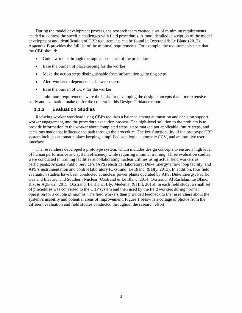
The researchers developed a prototype system, which includes design concepts to ensure a high level of human performance and system efficiency while requiring minimal training. Three evaluation studies were conducted in training facilities at collaborating nuclear utilities using actual field workers as participants: Arizona Public Service’s (APS) electrical laboratory, Duke Energy’s flow loop facility, and APS’s instrumentation and control laboratory (Oxstrand, Le Blanc, & Bly, 2013). In addition, four field evaluation studies have been conducted at nuclear power plants operated by APS, Duke Energy, Pacific Gas and Electric, and Southern Nuclear (Oxstrand & Le Blanc, 2014; Oxstrand, Al Rashdan, Le Blanc, Bly, & Agarwal, 2015; Oxstrand, Le Blanc, Bly, Medema, & Hill, 2015). In each field study, a small set of procedures was converted to the CBP system and then used by the field workers during normal operation for a couple of months. The field workers then provided feedback to the researchers about the system’s usability and potential areas of improvement. Figure 1 below is a collage of photos from the different evaluation and field studies conducted throughout the research effort.
4
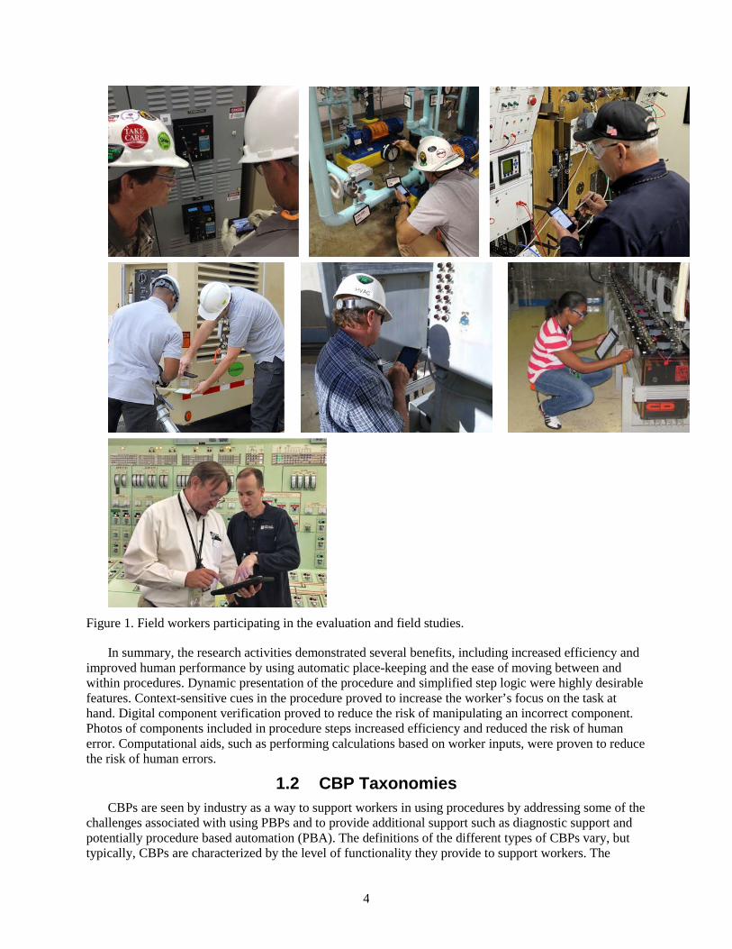
Figure 1. Field workers participating in the evaluation and field studies.
In summary, the research activities demonstrated several benefits, including increased efficiency and improved human performance by using automatic place-keeping and the ease of moving between and within procedures. Dynamic presentation of the procedure and simplified step logic were highly desirable features. Context-sensitive cues in the procedure proved to increase the worker’s focus on the task at hand. Digital component verification proved to reduce the risk of manipulating an incorrect component. Photos of components included in procedure steps increased efficiency and reduced the risk of human error. Computational aids, such as performing calculations based on worker inputs, were proven to reduce the risk of human errors.
1.2 CBP Taxonomies CBPs are seen by industry as a way to support workers in using procedures by addressing some of the
challenges associated with using PBPs and to provide additional support such as diagnostic support and potentially procedure based automation (PBA). The definitions of the different types of CBPs vary, but typically, CBPs are characterized by the level of functionality they provide to support workers. The
5
functionality of CBPs can vary from being a static digital copy of the paper procedure (such as a pdf copy of the PBP) to a fully integrated CBP system that is capable of executing sequences of procedural actions automatically (referred to as PBA). Definitions for different types of CBPs have been put forth in several guidance documents. Some of the documents, such as IEEE 1786 (2011) were developed with control room CBPs. While others, such as the guidance provided by EPRI for Smart documents (EPRI, 2015b) and Nuclear Electronic Work Packages - Enterprise Requirements (NEWPER) are intended to cover work package instructions.
Though the number and specific description of CBP types varies by document, the classification of CBPs typically starts with a digital replica of the PBP as the lowest level and finishes with a CBP with the capability to automatically control the plant as the highest level. Intermediate levels include worker support capabilities such as linking to supplemental information, links to soft controls that reside in the control room HSI, embedded process data displays, and automatic evaluation of procedure logic. The level of worker support afforded by the CBP has important implications for how the CBP system can help to address challenges of PBPs and for how the CBP systems may affect the worker’s roles and responsibilities in the control room.
The way a CBP is characterized affects the functionality provided by the system, and the guidance that is utilized to design the system. It is important to understand the taxonomies provided by existing guidance, and the limitations in those characterizations, to enable development of effective guidance on how to design a system. This work specifically addresses instructions for workers in the field, and is adopting the NEWPER taxonomy described in section 1.2.3. However, many of the concepts can be applied in control room procedures.
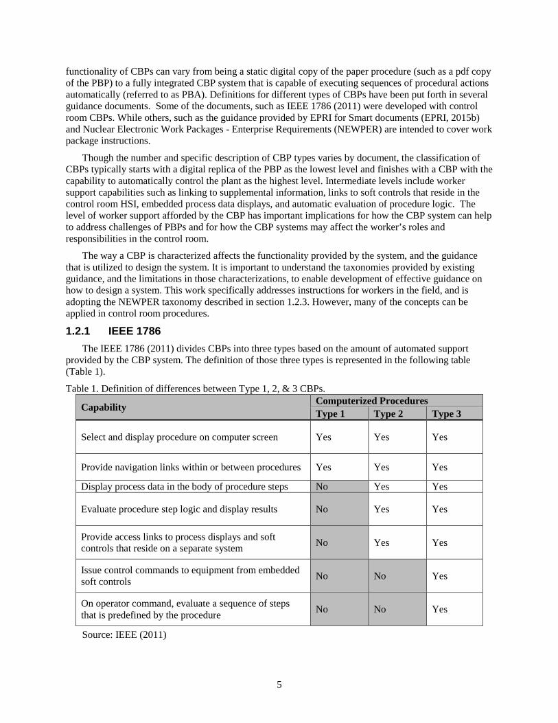
1.2.1 IEEE 1786 The IEEE 1786 (2011) divides CBPs into three types based on the amount of automated support
provided by the CBP system. The definition of those three types is represented in the following table (Table 1).
Table 1. Definition of differences between Type 1, 2, & 3 CBPs.
Capability Computerized Procedures Type 1 Type 2 Type 3
Select and display procedure on computer screen Yes Yes Yes
Provide navigation links within or between procedures Yes Yes Yes
Display process data in the body of procedure steps No Yes Yes
Evaluate procedure step logic and display results No Yes Yes
Provide access links to process displays and soft controls that reside on a separate system No Yes Yes
Issue control commands to equipment from embedded soft controls No No Yes
On operator command, evaluate a sequence of steps that is predefined by the procedure No No Yes
Source: IEEE (2011)
6
1.2.2 EPRI – Smart Documents In the report “Improving the Execution and Productivity of Maintenance with Electronic Work
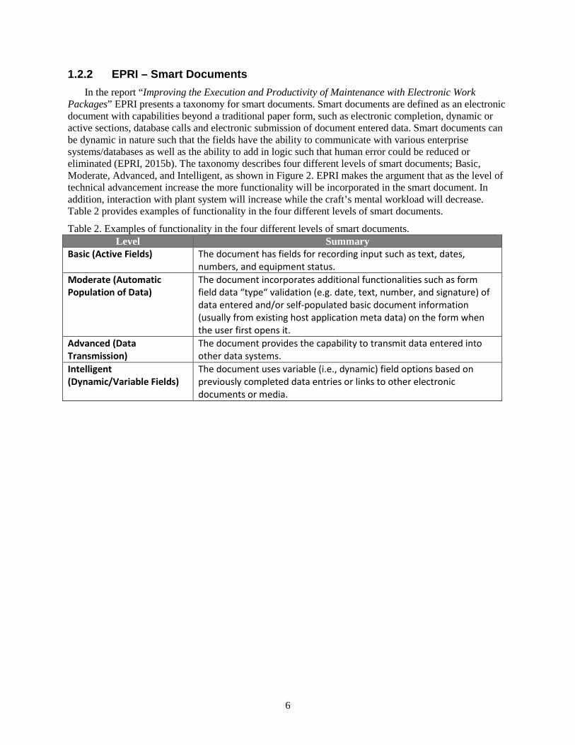
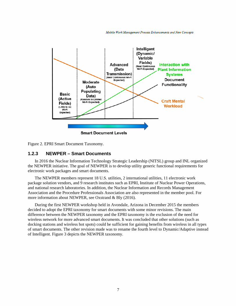
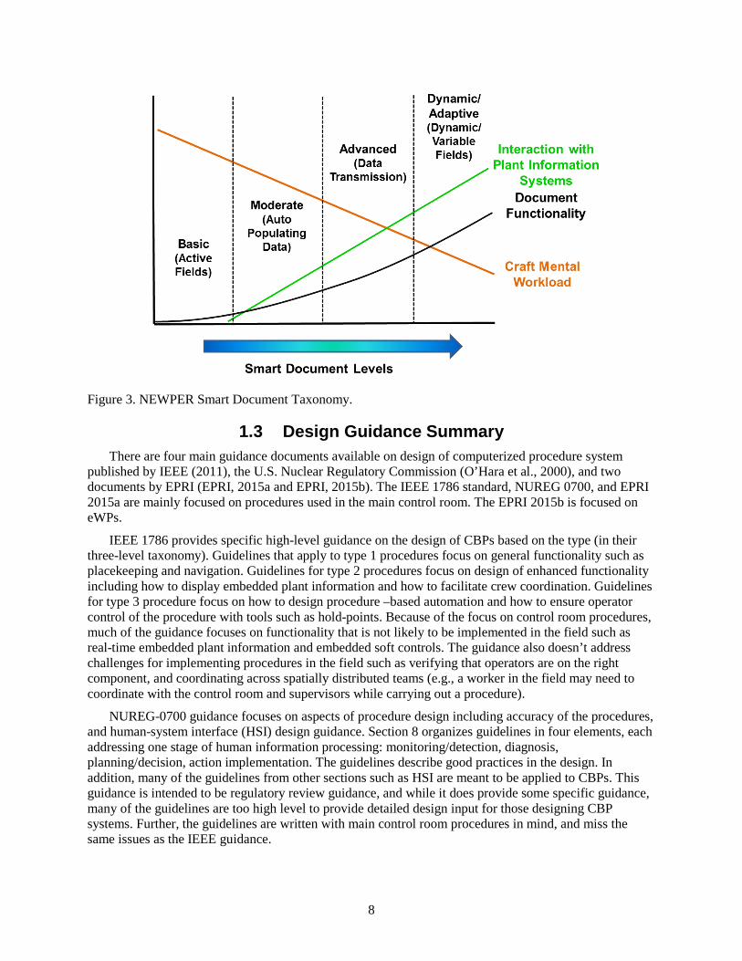
Packages” EPRI presents a taxonomy for smart documents. Smart documents are defined as an electronic document with capabilities beyond a traditional paper form, such as electronic completion, dynamic or active sections, database calls and electronic submission of document entered data. Smart documents can be dynamic in nature such that the fields have the ability to communicate with various enterprise systems/databases as well as the ability to add in logic such that human error could be reduced or eliminated (EPRI, 2015b). The taxonomy describes four different levels of smart documents; Basic, Moderate, Advanced, and Intelligent, as shown in Figure 2. EPRI makes the argument that as the level of technical advancement increase the more functionality will be incorporated in the smart document. In addition, interaction with plant system will increase while the craft’s mental workload will decrease. Table 2 provides examples of functionality in the four different levels of smart documents.
Table 2. Examples of functionality in the four different levels of smart documents. Level Summary
Basic (Active Fields) The document has fields for recording input such as text, dates, numbers, and equipment status.
Moderate (Automatic Population of Data)
The document incorporates additional functionalities such as form field data “type“ validation (e.g. date, text, number, and signature) of data entered and/or self-populated basic document information (usually from existing host application meta data) on the form when the user first opens it.
Advanced (Data Transmission)
The document provides the capability to transmit data entered into other data systems.
Intelligent (Dynamic/Variable Fields)
The document uses variable (i.e., dynamic) field options based on previously completed data entries or links to other electronic documents or media.
7
Figure 2. EPRI Smart Document Taxonomy.
1.2.3 NEWPER – Smart Documents In 2016 the Nuclear Information Technology Strategic Leadership (NITSL) group and INL organized
the NEWPER initiative. The goal of NEWPER is to develop utility generic functional requirements for electronic work packages and smart documents.
The NEWPER members represent 18 U.S. utilities, 2 international utilities, 11 electronic work package solution vendors, and 9 research institutes such as EPRI, Institute of Nuclear Power Operations, and national research laboratories. In addition, the Nuclear Information and Records Management Association and the Procedure Professionals Association are also represented in the member pool. For more information about NEWPER, see Oxstrand & Bly (2016).
During the first NEWPER workshop held in Avondale, Arizona in December 2015 the members decided to adopt the EPRI taxonomy for smart documents with some minor revisions. The main difference between the NEWPER taxonomy and the EPRI taxonomy is the exclusion of the need for wireless network for more advanced smart documents. It was concluded that other solutions (such as docking stations and wireless hot spots) could be sufficient for gaining benefits from wireless in all types of smart documents. The other revision made was to rename the fourth level to Dynamic/Adaptive instead of Intelligent. Figure 3 depicts the NEWPER taxonomy.
8
Figure 3. NEWPER Smart Document Taxonomy.
1.3 Design Guidance Summary There are four main guidance documents available on design of computerized procedure system
published by IEEE (2011), the U.S. Nuclear Regulatory Commission (O’Hara et al., 2000), and two documents by EPRI (EPRI, 2015a and EPRI, 2015b). The IEEE 1786 standard, NUREG 0700, and EPRI 2015a are mainly focused on procedures used in the main control room. The EPRI 2015b is focused on eWPs.
IEEE 1786 provides specific high-level guidance on the design of CBPs based on the type (in their three-level taxonomy). Guidelines that apply to type 1 procedures focus on general functionality such as placekeeping and navigation. Guidelines for type 2 procedures focus on design of enhanced functionality including how to display embedded plant information and how to facilitate crew coordination. Guidelines for type 3 procedure focus on how to design procedure –based automation and how to ensure operator control of the procedure with tools such as hold-points. Because of the focus on control room procedures, much of the guidance focuses on functionality that is not likely to be implemented in the field such as real-time embedded plant information and embedded soft controls. The guidance also doesn’t address challenges for implementing procedures in the field such as verifying that operators are on the right component, and coordinating across spatially distributed teams (e.g., a worker in the field may need to coordinate with the control room and supervisors while carrying out a procedure).
NUREG-0700 guidance focuses on aspects of procedure design including accuracy of the procedures, and human-system interface (HSI) design guidance. Section 8 organizes guidelines in four elements, each addressing one stage of human information processing: monitoring/detection, diagnosis, planning/decision, action implementation. The guidelines describe good practices in the design. In addition, many of the guidelines from other sections such as HSI are meant to be applied to CBPs. This guidance is intended to be regulatory review guidance, and while it does provide some specific guidance, many of the guidelines are too high level to provide detailed design input for those designing CBP systems. Further, the guidelines are written with main control room procedures in mind, and miss the same issues as the IEEE guidance.

9
The EPRI technical report “Human Factors Guidance for Control Room and Digital Human-System Interface Design and Modification” from 2015 provides guidelines for planning, specification, design, licensing, implementation, training, operation, and maintenance for operating plants and new builds (EPRI, 2015a). The specific parts of the guidance dedicated to procedures focuses mainly on control room procedures. However, the document covers how the guidance can/should be applied to procedures used by field workers as well. The document provides guidance on interaction between the procedure development and the human factors engineering activities such as, integrating operational experience, use of function allocation to determine if an action should be conducted by the human or be automated, and the integration of training and procedure development. The guidelines provided for CBP design in the EPARI report are applicable to all types of procedures used at the nuclear power plants including emergency operating procedures, alarm procedures, and field procedures. The guidelines are also applicable to multiple types of CBPs. EPRI based their guidance on the three types defined by IEEE. Similar to the NUREG-0700, both EPRI guidance documents (EPRI, 2015a and 2015b) provides high level guidance which does not provide enough information about how to apply the human factors guidance and how to best design the CBP system.
Even though the EPRI technical report “Improving the Execution and Productivity of Maintenance with Electronic Work Packages” is not a design guidance per se it does provide suggestions for functionality to be included in an eWP system. There are some specific suggestions targeting smart documents, however, almost none of these suggestions are related to the more advanced smart documents. CBPs are briefly mentioned in the report, but no design guidance or suggestion are provided for this type of procedures.
In conclusion, the majority of the existing guidance on CBPs is intended for control room CBP systems, and does not necessarily address the challenges of designing CBP systems for instructions carried out in the field. Further, the guidance is often presented on a high level, which leaves the designer to interpret what is meant by the guidance and how to specifically implement it. The purpose of this document is to provide guidance specifically tailored to instructions that are carried out in the field based on the authors’ experience working with several types of work instructions including maintenance procedures, field operating procedures, surveillance procedures, and work orders. Also provided are specific examples of how to implement the guidance. The examples are not meant to define the only way to implement the guidance, but are meant as a useful tool to illustrate the concepts for the designer.
10
2. DESIGN REQUIREMENTS The design requirements in this report are presented as several high-level design principles that are
essential for an effective CBP system. Following each high level design principle are a several specific examples of situations in which the high-level principles were implemented. These examples help illustrate concrete examples of how these design principles should be implemented. These specific and concrete illustrations fill a gap in the existing guidance for CBPs and should help designers to understand what is meant by the design requirements. Further, the examples presented in this document are drawn from experience with instructions from several different utilities and several different organizations within each utility. Therefore, the examples cover a wide range of instruction types and situations, which should provide CBP designers with a strong foundation for implementing the design requirements.
2.1 Provide Context Sensitive Information Everywhere Possible With dynamic CBPs, the procedure content can update based on the current situation, unlike static
PBPS. A dynamic context sensitive CBP allows the worker to focus on the task at hand rather than spending effort on understanding which steps and conditions apply for the current task and plant state. Context sensitivity means the procedure will update based on current operation mode, plant conditions, and decisions made and values recorded previously in the task execution. A CBP system designed this way will guide the worker through the applicable procedure path while automatically marking steps not applicable to the current context. The dynamic context sensitive procedure reduces the risk of unintentionally conducting the incorrect section of the procedure or marking applicable steps as not applicable.
Context sensitivity can be incorporated in a variety of ways. For example, the desired initial state (as found) or outcome state (as left) will provide context about the task at hand. Another example is to use context sensitive cues in the procedure steps themselves. Research shows that non-invasive context sensitive cues in steps serve an effective, yet subtle reminder of the task at hand and actions required of the worker (Oxstrand, Le Blanc, & Bly, 2013). The CBP system should be context-sensitive anywhere that the necessary information is available.
2.1.1 Context Sensitive Information – Equipment State If the procedure calls for checking or modifying the state of equipment, such as changing a valve
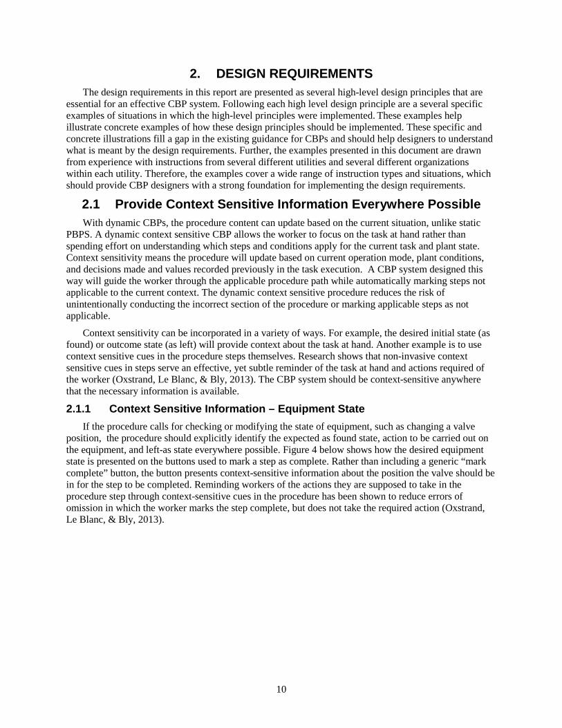
position, the procedure should explicitly identify the expected as found state, action to be carried out on the equipment, and left-as state everywhere possible. Figure 4 below shows how the desired equipment state is presented on the buttons used to mark a step as complete. Rather than including a generic “mark complete” button, the button presents context-sensitive information about the position the valve should be in for the step to be completed. Reminding workers of the actions they are supposed to take in the procedure step through context-sensitive cues in the procedure has been shown to reduce errors of omission in which the worker marks the step complete, but does not take the required action (Oxstrand, Le Blanc, & Bly, 2013).
11
Figure 4. Example of desired equipment state.
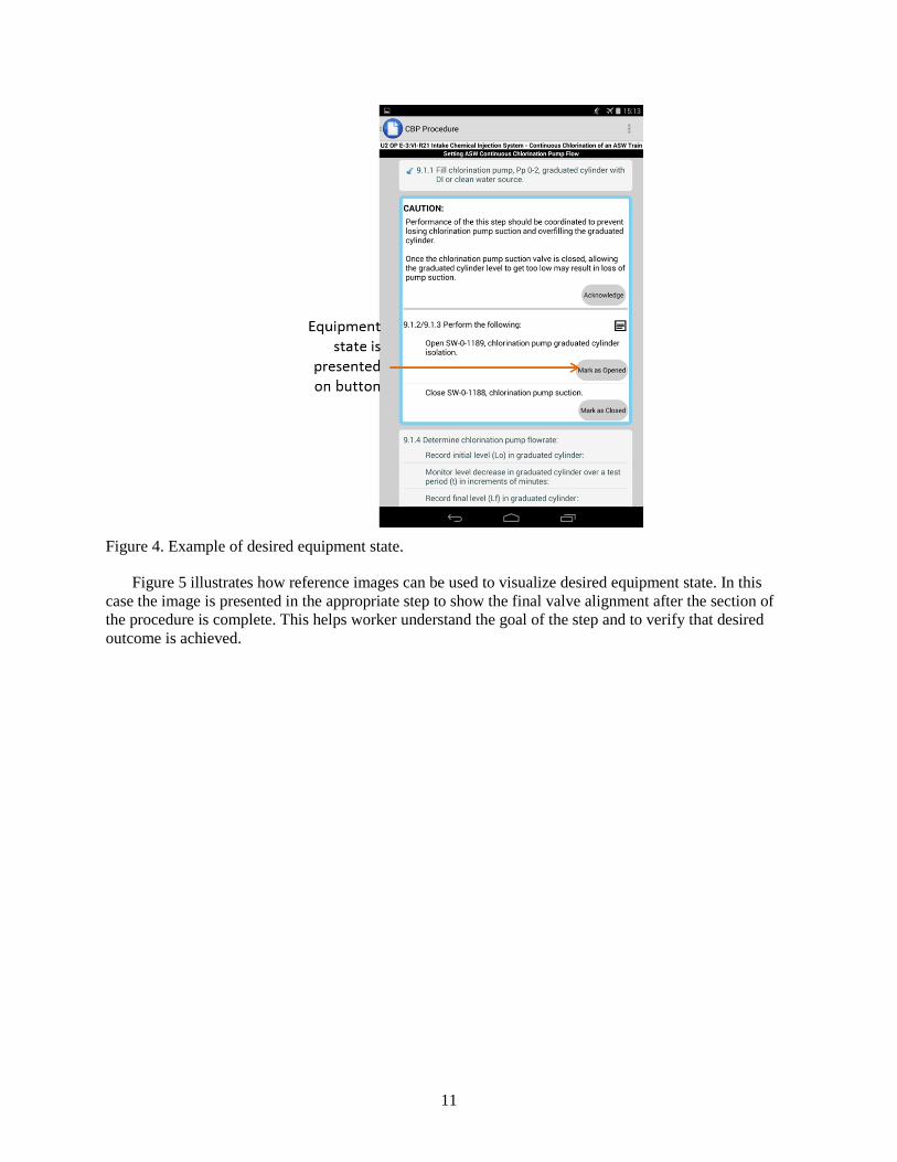
Figure 5 illustrates how reference images can be used to visualize desired equipment state. In this case the image is presented in the appropriate step to show the final valve alignment after the section of the procedure is complete. This helps worker understand the goal of the step and to verify that desired outcome is achieved.
12
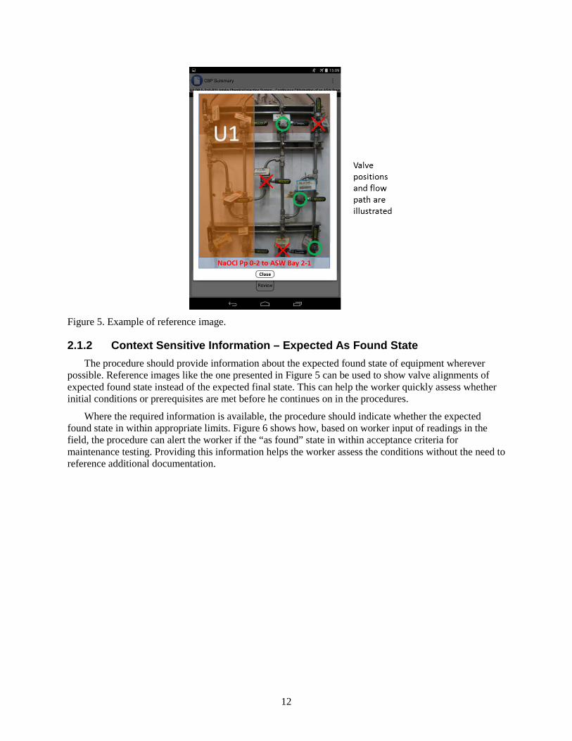
Figure 5. Example of reference image.
2.1.2 Context Sensitive Information – Expected As Found State The procedure should provide information about the expected found state of equipment wherever
possible. Reference images like the one presented in Figure 5 can be used to show valve alignments of expected found state instead of the expected final state. This can help the worker quickly assess whether initial conditions or prerequisites are met before he continues on in the procedures.
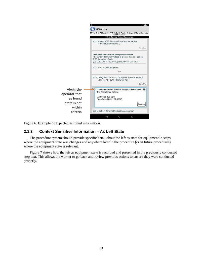
Where the required information is available, the procedure should indicate whether the expected found state in within appropriate limits. Figure 6 shows how, based on worker input of readings in the field, the procedure can alert the worker if the “as found” state in within acceptance criteria for maintenance testing. Providing this information helps the worker assess the conditions without the need to reference additional documentation.
13
Figure 6. Example of expected as found information.
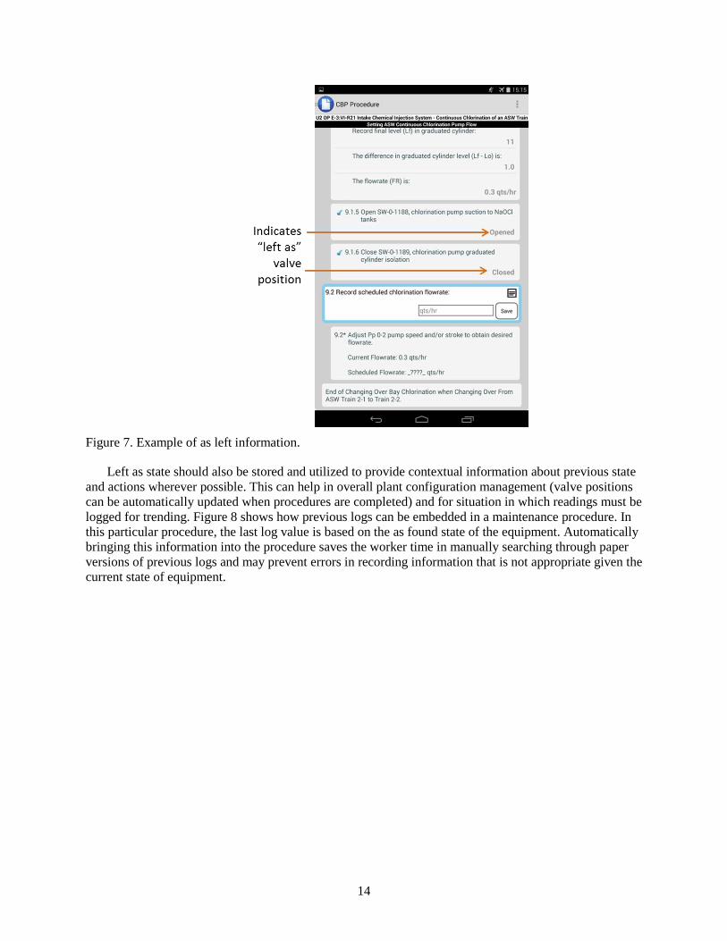
2.1.3 Context Sensitive Information – As Left State The procedure system should provide specific detail about the left as state for equipment in steps
where the equipment state was changes and anywhere later in the procedure (or in future procedures) where the equipment state is relevant.
Figure 7 shows how the left as equipment state is recorded and presented in the previously conducted step text. This allows the worker to go back and review previous actions to ensure they were conducted properly.
14
Figure 7. Example of as left information.
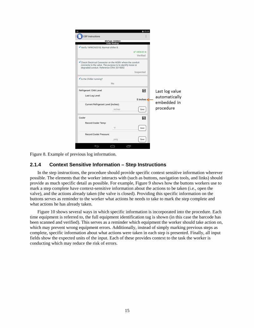
Left as state should also be stored and utilized to provide contextual information about previous state and actions wherever possible. This can help in overall plant configuration management (valve positions can be automatically updated when procedures are completed) and for situation in which readings must be logged for trending. Figure 8 shows how previous logs can be embedded in a maintenance procedure. In this particular procedure, the last log value is based on the as found state of the equipment. Automatically bringing this information into the procedure saves the worker time in manually searching through paper versions of previous logs and may prevent errors in recording information that is not appropriate given the current state of equipment.
15
Figure 8. Example of previous log information.
2.1.4 Context Sensitive Information – Step Instructions In the step instructions, the procedure should provide specific context sensitive information wherever
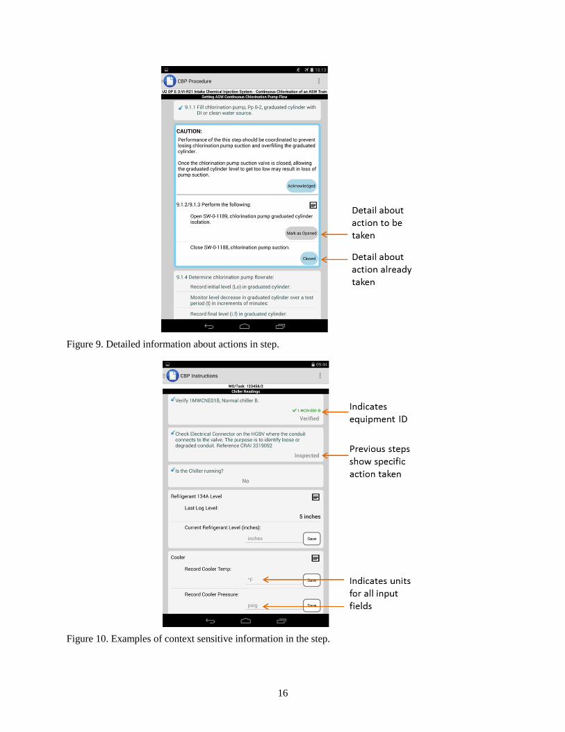
possible. The elements that the worker interacts with (such as buttons, navigation tools, and links) should provide as much specific detail as possible. For example, Figure 9 shows how the buttons workers use to mark a step complete have context-sensitive information about the actions to be taken (i.e., open the valve), and the actions already taken (the valve is closed). Providing this specific information on the buttons serves as reminder to the worker what actions he needs to take to mark the step complete and what actions he has already taken.
Figure 10 shows several ways in which specific information is incorporated into the procedure. Each time equipment is referred to, the full equipment identification tag is shown (in this case the barcode has been scanned and verified). This serves as a reminder which equipment the worker should take action on, which may prevent wrong equipment errors. Additionally, instead of simply marking previous steps as complete, specific information about what actions were taken in each step is presented. Finally, all input fields show the expected units of the input. Each of these provides context to the task the worker is conducting which may reduce the risk of errors.
16
Figure 9. Detailed information about actions in step.
Figure 10. Examples of context sensitive information in the step.
17
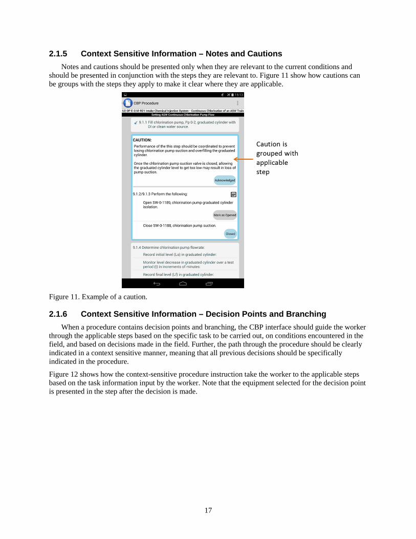
2.1.5 Context Sensitive Information – Notes and Cautions Notes and cautions should be presented only when they are relevant to the current conditions and
should be presented in conjunction with the steps they are relevant to. Figure 11 show how cautions can be groups with the steps they apply to make it clear where they are applicable.
Figure 11. Example of a caution.
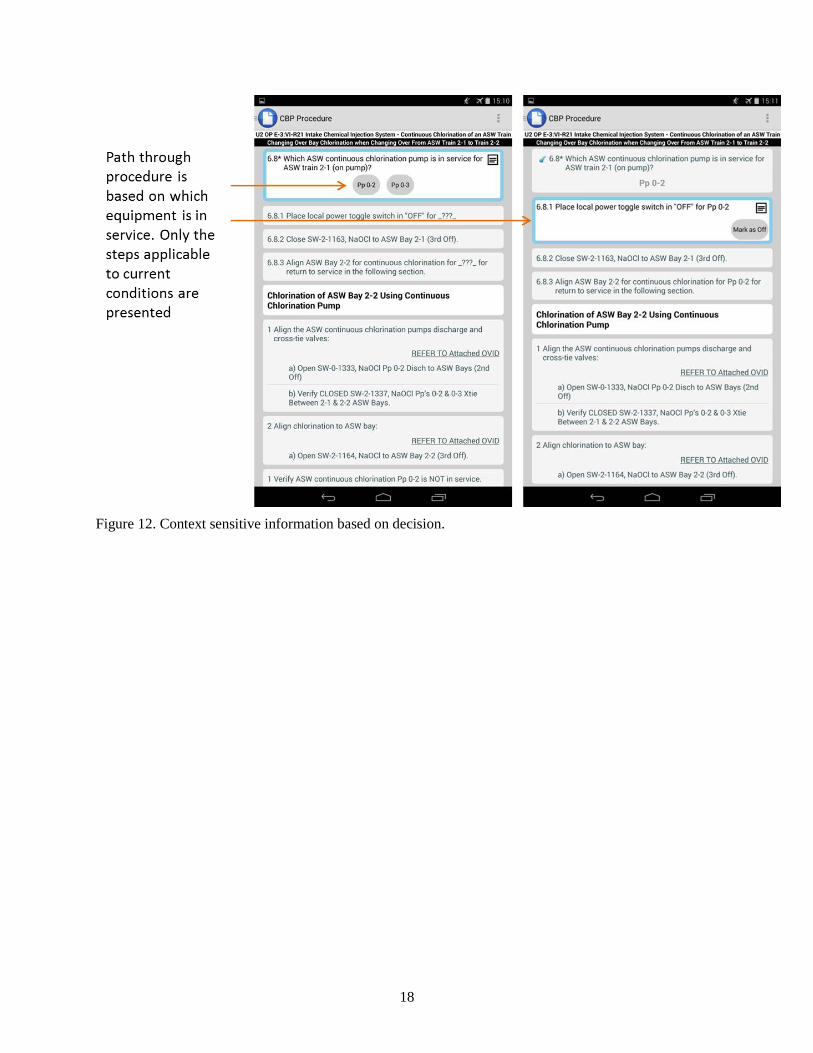
2.1.6 Context Sensitive Information – Decision Points and Branching When a procedure contains decision points and branching, the CBP interface should guide the worker
through the applicable steps based on the specific task to be carried out, on conditions encountered in the field, and based on decisions made in the field. Further, the path through the procedure should be clearly indicated in a context sensitive manner, meaning that all previous decisions should be specifically indicated in the procedure.
Figure 12 shows how the context-sensitive procedure instruction take the worker to the applicable steps based on the task information input by the worker. Note that the equipment selected for the decision point is presented in the step after the decision is made.
18
Figure 12. Context sensitive information based on decision.
19
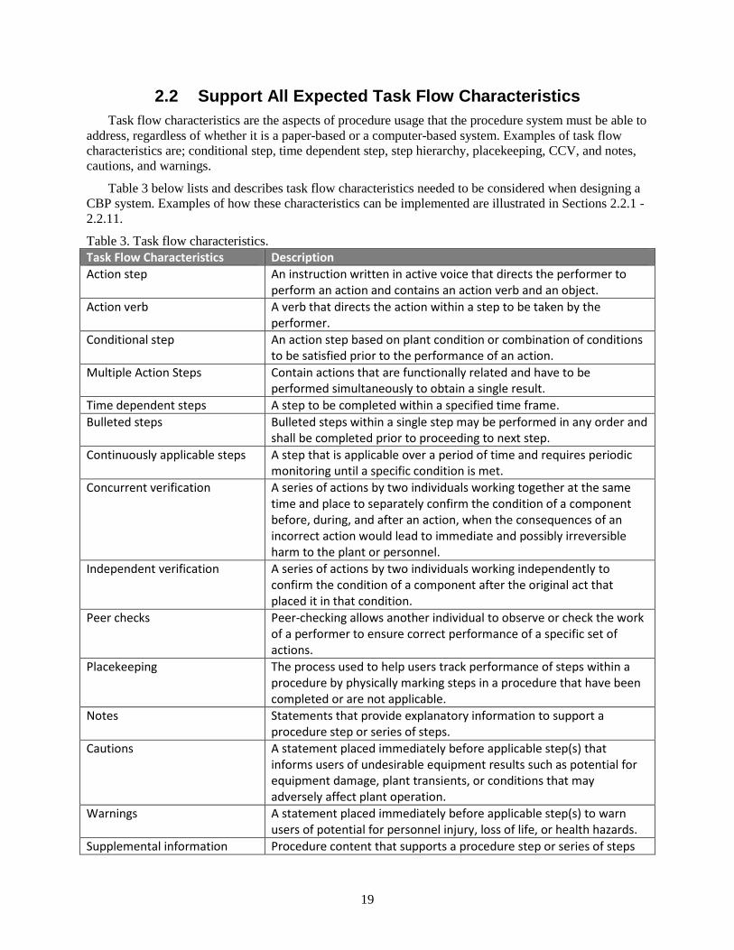
2.2 Support All Expected Task Flow Characteristics Task flow characteristics are the aspects of procedure usage that the procedure system must be able to
address, regardless of whether it is a paper-based or a computer-based system. Examples of task flow characteristics are; conditional step, time dependent step, step hierarchy, placekeeping, CCV, and notes, cautions, and warnings.
Table 3 below lists and describes task flow characteristics needed to be considered when designing a CBP system. Examples of how these characteristics can be implemented are illustrated in Sections 2.2.1 - 2.2.11.
Table 3. Task flow characteristics. Task Flow Characteristics Description Action step An instruction written in active voice that directs the performer to
perform an action and contains an action verb and an object. Action verb A verb that directs the action within a step to be taken by the
performer. Conditional step An action step based on plant condition or combination of conditions
to be satisfied prior to the performance of an action. Multiple Action Steps Contain actions that are functionally related and have to be
performed simultaneously to obtain a single result. Time dependent steps A step to be completed within a specified time frame. Bulleted steps Bulleted steps within a single step may be performed in any order and
shall be completed prior to proceeding to next step. Continuously applicable steps A step that is applicable over a period of time and requires periodic
monitoring until a specific condition is met. Concurrent verification A series of actions by two individuals working together at the same
time and place to separately confirm the condition of a component before, during, and after an action, when the consequences of an incorrect action would lead to immediate and possibly irreversible harm to the plant or personnel.
Independent verification A series of actions by two individuals working independently to confirm the condition of a component after the original act that placed it in that condition.
Peer checks Peer-checking allows another individual to observe or check the work of a performer to ensure correct performance of a specific set of actions.
Placekeeping The process used to help users track performance of steps within a procedure by physically marking steps in a procedure that have been completed or are not applicable.
Notes Statements that provide explanatory information to support a procedure step or series of steps.
Cautions A statement placed immediately before applicable step(s) that informs users of undesirable equipment results such as potential for equipment damage, plant transients, or conditions that may adversely affect plant operation.
Warnings A statement placed immediately before applicable step(s) to warn users of potential for personnel injury, loss of life, or health hazards.
Supplemental information Procedure content that supports a procedure step or series of steps
20
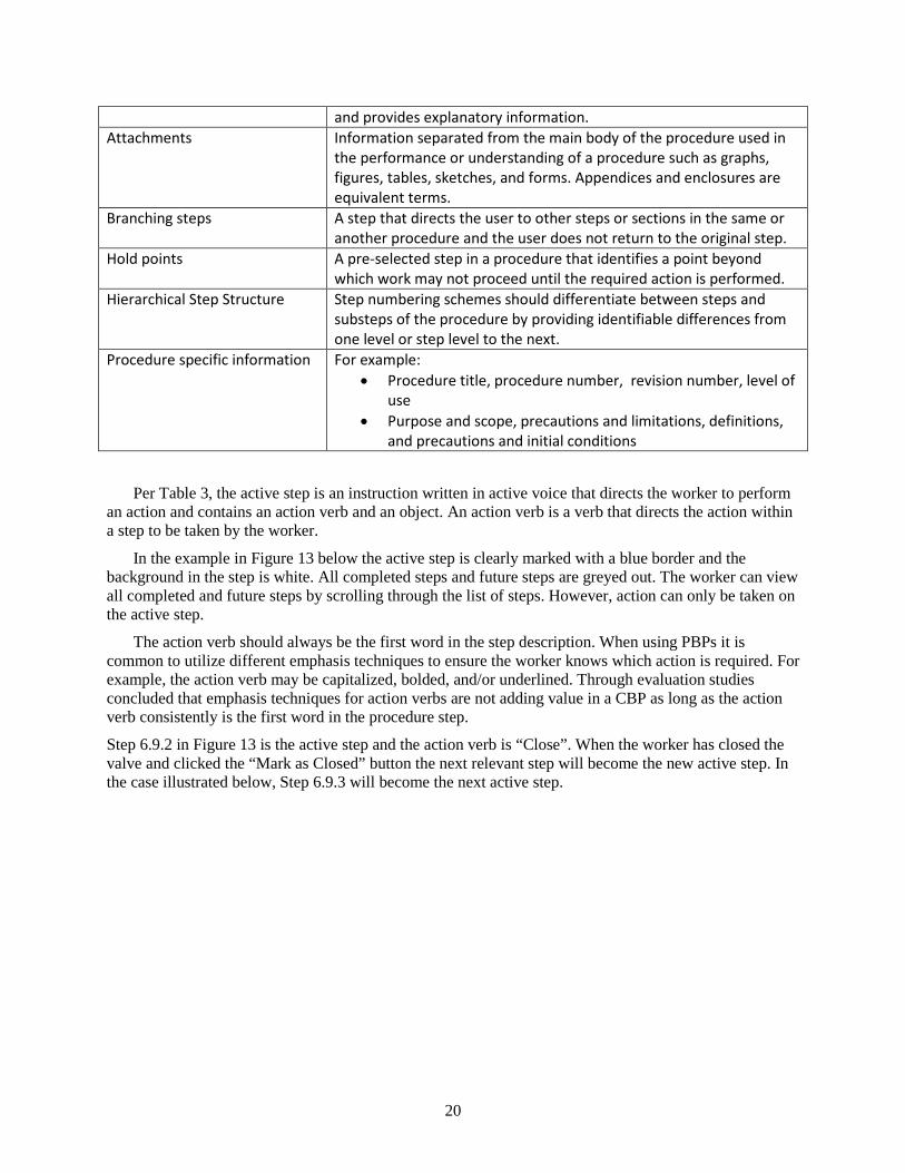
and provides explanatory information. Attachments Information separated from the main body of the procedure used in
the performance or understanding of a procedure such as graphs, figures, tables, sketches, and forms. Appendices and enclosures are equivalent terms.
Branching steps A step that directs the user to other steps or sections in the same or another procedure and the user does not return to the original step.
Hold points A pre-selected step in a procedure that identifies a point beyond which work may not proceed until the required action is performed.
Hierarchical Step Structure Step numbering schemes should differentiate between steps and substeps of the procedure by providing identifiable differences from one level or step level to the next.
Procedure specific information For example: • Procedure title, procedure number, revision number, level of
use • Purpose and scope, precautions and limitations, definitions,
and precautions and initial conditions
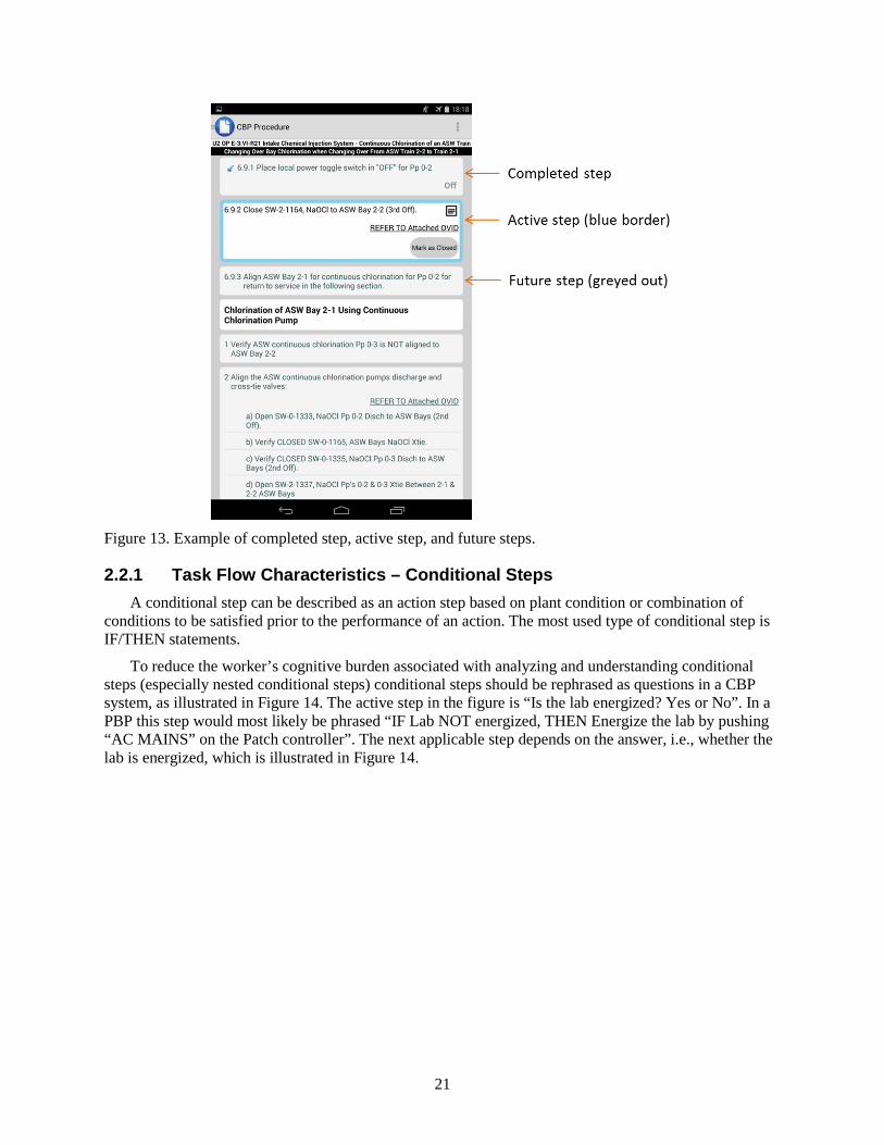
Per Table 3, the active step is an instruction written in active voice that directs the worker to perform an action and contains an action verb and an object. An action verb is a verb that directs the action within a step to be taken by the worker.
In the example in Figure 13 below the active step is clearly marked with a blue border and the background in the step is white. All completed steps and future steps are greyed out. The worker can view all completed and future steps by scrolling through the list of steps. However, action can only be taken on the active step.
The action verb should always be the first word in the step description. When using PBPs it is common to utilize different emphasis techniques to ensure the worker knows which action is required. For example, the action verb may be capitalized, bolded, and/or underlined. Through evaluation studies concluded that emphasis techniques for action verbs are not adding value in a CBP as long as the action verb consistently is the first word in the procedure step.
Step 6.9.2 in Figure 13 is the active step and the action verb is “Close”. When the worker has closed the valve and clicked the “Mark as Closed” button the next relevant step will become the new active step. In the case illustrated below, Step 6.9.3 will become the next active step.
21
Figure 13. Example of completed step, active step, and future steps.
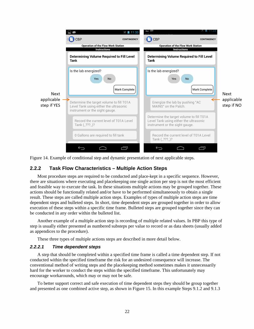
2.2.1 Task Flow Characteristics – Conditional Steps A conditional step can be described as an action step based on plant condition or combination of
conditions to be satisfied prior to the performance of an action. The most used type of conditional step is IF/THEN statements.
To reduce the worker’s cognitive burden associated with analyzing and understanding conditional steps (especially nested conditional steps) conditional steps should be rephrased as questions in a CBP system, as illustrated in Figure 14. The active step in the figure is “Is the lab energized? Yes or No”. In a PBP this step would most likely be phrased “IF Lab NOT energized, THEN Energize the lab by pushing “AC MAINS” on the Patch controller”. The next applicable step depends on the answer, i.e., whether the lab is energized, which is illustrated in Figure 14.
22
Figure 14. Example of conditional step and dynamic presentation of next applicable steps.
2.2.2 Task Flow Characteristics – Multiple Action Steps Most procedure steps are required to be conducted and place-kept in a specific sequence. However,
there are situations where executing and placekeeping one single action per step is not the most efficient and feasible way to execute the task. In these situations multiple actions may be grouped together. These actions should be functionally related and/or have to be performed simultaneously to obtain a single result. These steps are called multiple action steps. Examples of types of multiple action steps are time dependent steps and bulleted steps. In short, time dependent steps are grouped together in order to allow execution of these steps within a specific time frame. Bulleted steps are grouped together since they can be conducted in any order within the bulleted list.
Another example of a multiple action step is recording of multiple related values. In PBP this type of step is usually either presented as numbered substeps per value to record or as data sheets (usually added as appendices to the procedure).
These three types of multiple actions steps are described in more detail below.
2.2.2.1 Time dependent steps A step that should be completed within a specified time frame is called a time dependent step. If not
conducted within the specified timeframe the risk for an undesired consequence will increase. The conventional method of writing steps and the placekeeping method sometimes makes it unnecessarily hard for the worker to conduct the steps within the specified timeframe. This unfortunately may encourage workarounds, which may or may not be safe.
To better support correct and safe execution of time dependent steps they should be group together and presented as one combined active step, as shown in Figure 15. In this example Steps 9.1.2 and 9.1.3
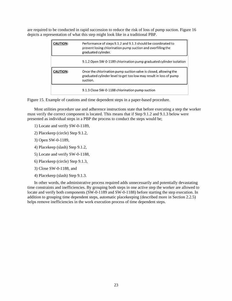
23
are required to be conducted in rapid succession to reduce the risk of loss of pump suction. Figure 16 depicts a representation of what this step might look like in a traditional PBP.
Figure 15. Example of cautions and time dependent steps in a paper-based procedure.
Most utilities procedure use and adherence instructions state that before executing a step the worker must verify the correct component is located. This means that if Step 9.1.2 and 9.1.3 below were presented as individual steps in a PBP the process to conduct the steps would be;
1) Locate and verify SW-0-1189,
2) Placekeep (circle) Step 9.1.2,
3) Open SW-0-1189,
4) Placekeep (slash) Step 9.1.2,
5) Locate and verify SW-0-1188,
6) Placekeep (circle) Step 9.1.3,
3) Close SW-0-1188, and
4) Placekeep (slash) Step 9.1.3.
In other words, the administrative process required adds unnecessarily and potentially devastating time constraints and inefficiencies. By grouping both steps in one active step the worker are allowed to locate and verify both components (SW-0-1189 and SW-0-1188) before starting the step execution. In addition to grouping time dependent steps, automatic placekeeping (described more in Section 2.2.5) helps remove inefficiencies in the work execution process of time dependent steps.
24
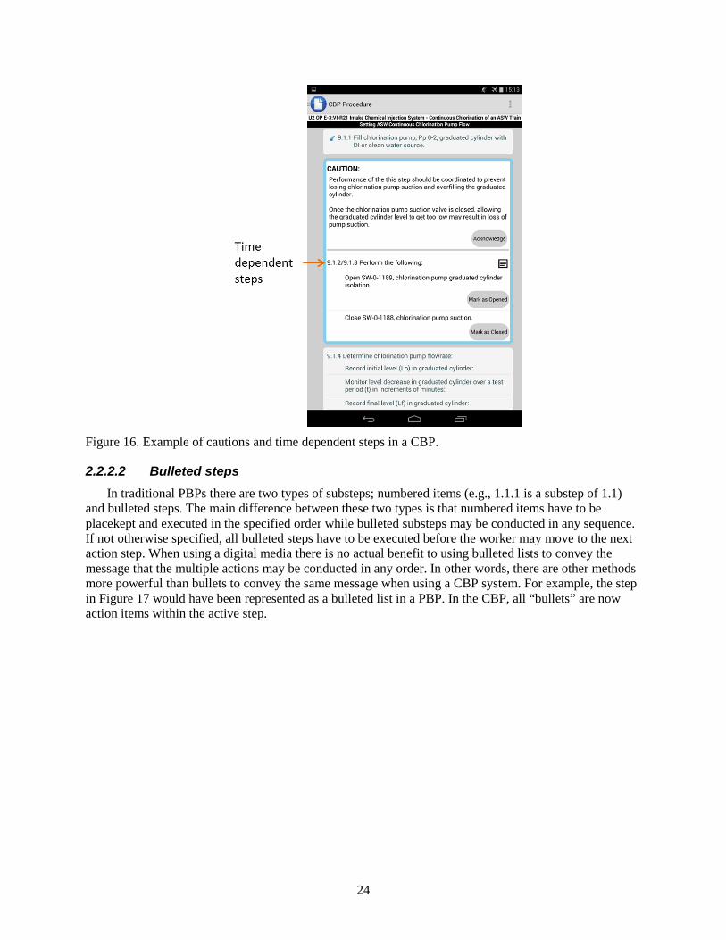
Figure 16. Example of cautions and time dependent steps in a CBP.
2.2.2.2 Bulleted steps In traditional PBPs there are two types of substeps; numbered items (e.g., 1.1.1 is a substep of 1.1)
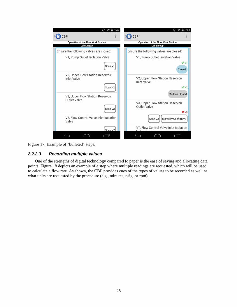
and bulleted steps. The main difference between these two types is that numbered items have to be placekept and executed in the specified order while bulleted substeps may be conducted in any sequence. If not otherwise specified, all bulleted steps have to be executed before the worker may move to the next action step. When using a digital media there is no actual benefit to using bulleted lists to convey the message that the multiple actions may be conducted in any order. In other words, there are other methods more powerful than bullets to convey the same message when using a CBP system. For example, the step in Figure 17 would have been represented as a bulleted list in a PBP. In the CBP, all “bullets” are now action items within the active step.
25
Figure 17. Example of "bulleted" steps.
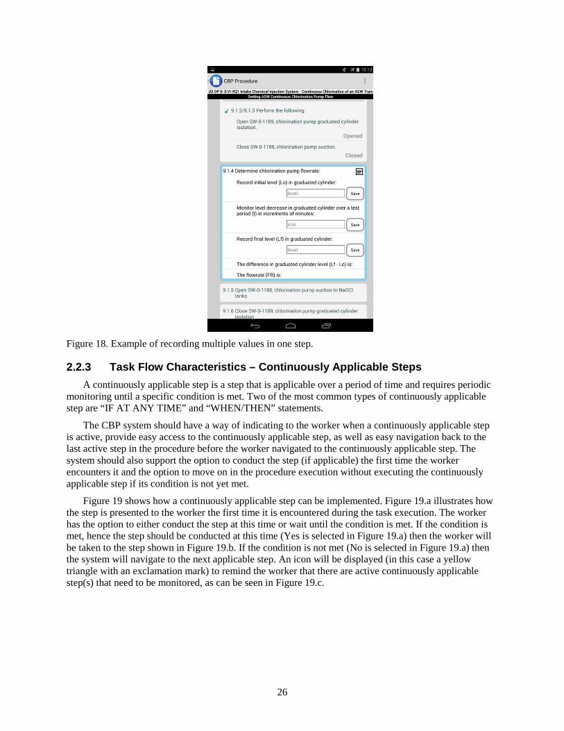
2.2.2.3 Recording multiple values One of the strengths of digital technology compared to paper is the ease of saving and allocating data
points. Figure 18 depicts an example of a step where multiple readings are requested, which will be used to calculate a flow rate. As shown, the CBP provides cues of the types of values to be recorded as well as what units are requested by the procedure (e.g., minutes, psig, or rpm).
26
Figure 18. Example of recording multiple values in one step.
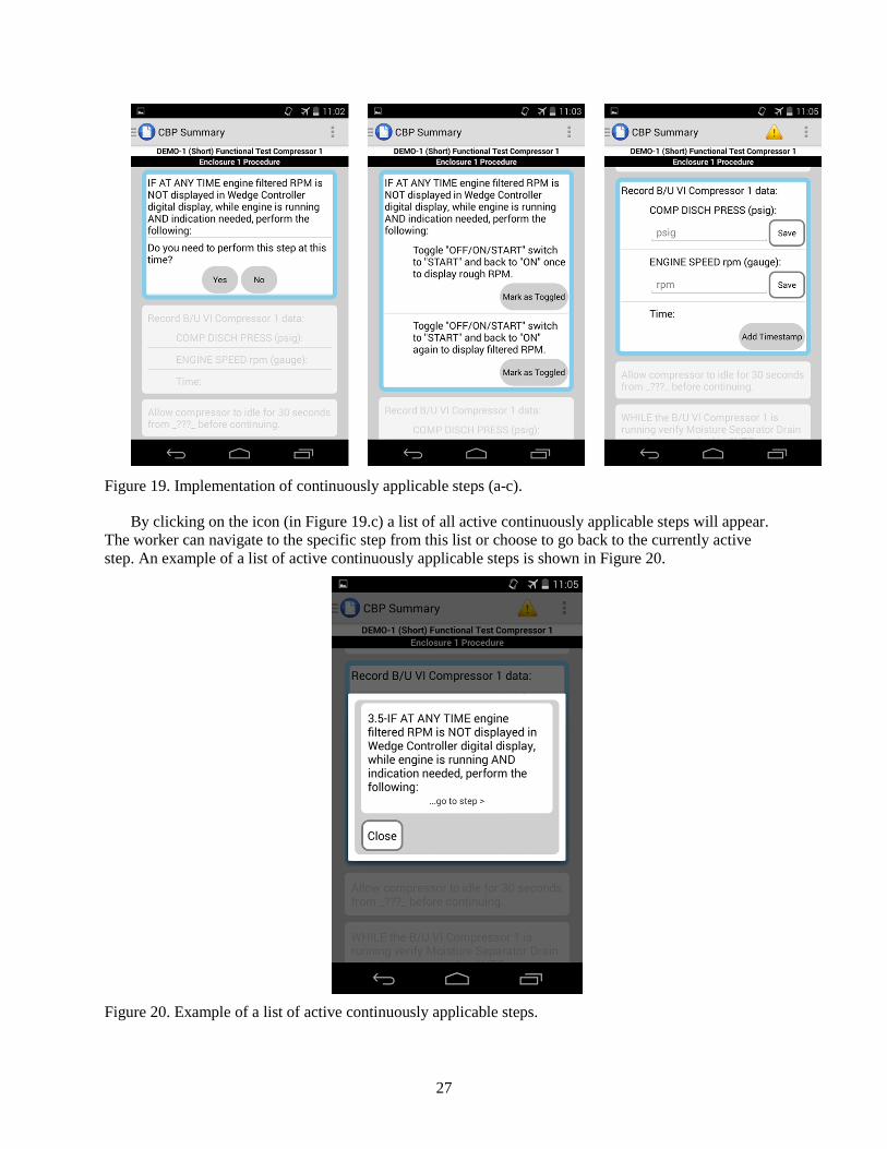
2.2.3 Task Flow Characteristics – Continuously Applicable Steps A continuously applicable step is a step that is applicable over a period of time and requires periodic
monitoring until a specific condition is met. Two of the most common types of continuously applicable step are “IF AT ANY TIME” and “WHEN/THEN” statements.
The CBP system should have a way of indicating to the worker when a continuously applicable step is active, provide easy access to the continuously applicable step, as well as easy navigation back to the last active step in the procedure before the worker navigated to the continuously applicable step. The system should also support the option to conduct the step (if applicable) the first time the worker encounters it and the option to move on in the procedure execution without executing the continuously applicable step if its condition is not yet met.
Figure 19 shows how a continuously applicable step can be implemented. Figure 19.a illustrates how the step is presented to the worker the first time it is encountered during the task execution. The worker has the option to either conduct the step at this time or wait until the condition is met. If the condition is met, hence the step should be conducted at this time (Yes is selected in Figure 19.a) then the worker will be taken to the step shown in Figure 19.b. If the condition is not met (No is selected in Figure 19.a) then the system will navigate to the next applicable step. An icon will be displayed (in this case a yellow triangle with an exclamation mark) to remind the worker that there are active continuously applicable step(s) that need to be monitored, as can be seen in Figure 19.c.
27
Figure 19. Implementation of continuously applicable steps (a-c).
By clicking on the icon (in Figure 19.c) a list of all active continuously applicable steps will appear. The worker can navigate to the specific step from this list or choose to go back to the currently active step. An example of a list of active continuously applicable steps is shown in Figure 20.
Figure 20. Example of a list of active continuously applicable steps.
28
2.2.4 Task Flow Characteristics – Peer-Checking, Concurrent and Independent Verification
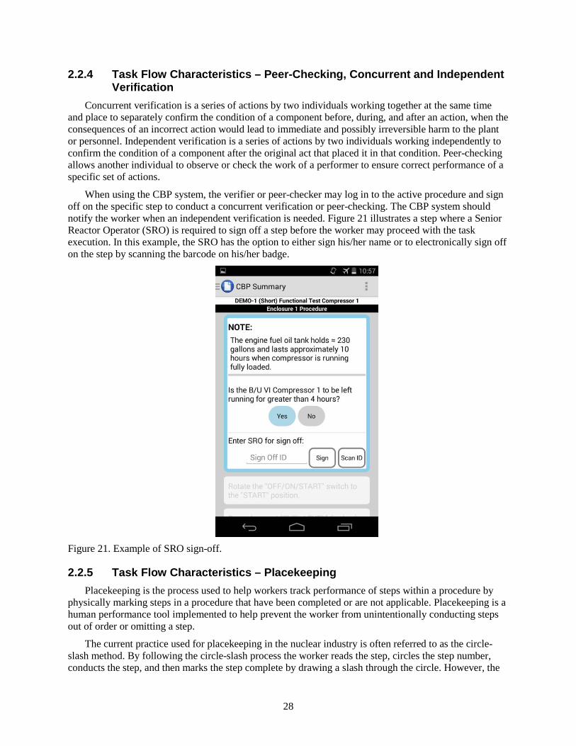
Concurrent verification is a series of actions by two individuals working together at the same time and place to separately confirm the condition of a component before, during, and after an action, when the consequences of an incorrect action would lead to immediate and possibly irreversible harm to the plant or personnel. Independent verification is a series of actions by two individuals working independently to confirm the condition of a component after the original act that placed it in that condition. Peer-checking allows another individual to observe or check the work of a performer to ensure correct performance of a specific set of actions.
When using the CBP system, the verifier or peer-checker may log in to the active procedure and sign off on the specific step to conduct a concurrent verification or peer-checking. The CBP system should notify the worker when an independent verification is needed. Figure 21 illustrates a step where a Senior Reactor Operator (SRO) is required to sign off a step before the worker may proceed with the task execution. In this example, the SRO has the option to either sign his/her name or to electronically sign off on the step by scanning the barcode on his/her badge.
Figure 21. Example of SRO sign-off.
2.2.5 Task Flow Characteristics – Placekeeping Placekeeping is the process used to help workers track performance of steps within a procedure by
physically marking steps in a procedure that have been completed or are not applicable. Placekeeping is a human performance tool implemented to help prevent the worker from unintentionally conducting steps out of order or omitting a step.
The current practice used for placekeeping in the nuclear industry is often referred to as the circle-slash method. By following the circle-slash process the worker reads the step, circles the step number, conducts the step, and then marks the step complete by drawing a slash through the circle. However, the
29
current practice of circle-slash where the worker is required to circle the step before reading it is quite an unnatural behavior for a human which may unnecessarily increase the risk of deviations.
To the extent possible, the CBP system should guide the worker to the next applicable step and help reduce the administrative burden of placekeeping. As described above, the CBP system should clearly identify the active step and make it distinctively different from already conducted steps as well as future steps. By only allowing the worker to take action on the active step, the CBP system has automatically placekept the step. In the background (i.e., not shown to the worker) information such as timestamp and who is conducting the step may be recorded by the CBP system.
This approach works well for procedures and instructions that have a well-defined sequence of steps. However, some procedures rely heavily on the skill-of-the-craft and/or it is not feasible to identify one specific path through the procedure. In these situations, automatic placekeeping will not be feasible. Hence, for these situations there needs to be a method for the worker to select the next step to execute. The selection of step to execute and the conclusion of the selected action step should be counted as placekeeping.
2.2.6 Task Flow Characteristics – Notes, Cautions, and Warnings Notes are statements that provide explanatory information to support a procedure step or series of
steps. A caution is a statement placed immediately before applicable step(s) that informs the worker of undesirable equipment results such as potential for equipment damage, plant transients, or conditions that may adversely affect plant operation. A warning is a statement placed immediately before applicable step(s) to warn the worker of potential for personnel injury, loss of life, or health hazards.
Figure 21 above shows an example of a note and Figure 16 illustrates a caution. As shown, notes, cautions, and warnings should be clearly associated with the step(s) they apply to. If it is desired to placekeep the note, caution, or warning an “Acknowledge” button should be added. By clicking this button the worker acknowledges that the note, caution, or warning has been read and understood.
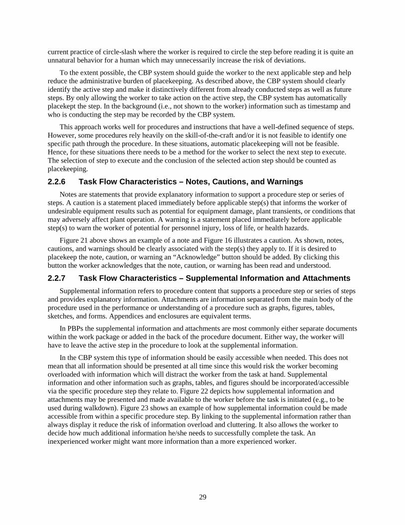
2.2.7 Task Flow Characteristics – Supplemental Information and Attachments Supplemental information refers to procedure content that supports a procedure step or series of steps
and provides explanatory information. Attachments are information separated from the main body of the procedure used in the performance or understanding of a procedure such as graphs, figures, tables, sketches, and forms. Appendices and enclosures are equivalent terms.
In PBPs the supplemental information and attachments are most commonly either separate documents within the work package or added in the back of the procedure document. Either way, the worker will have to leave the active step in the procedure to look at the supplemental information.
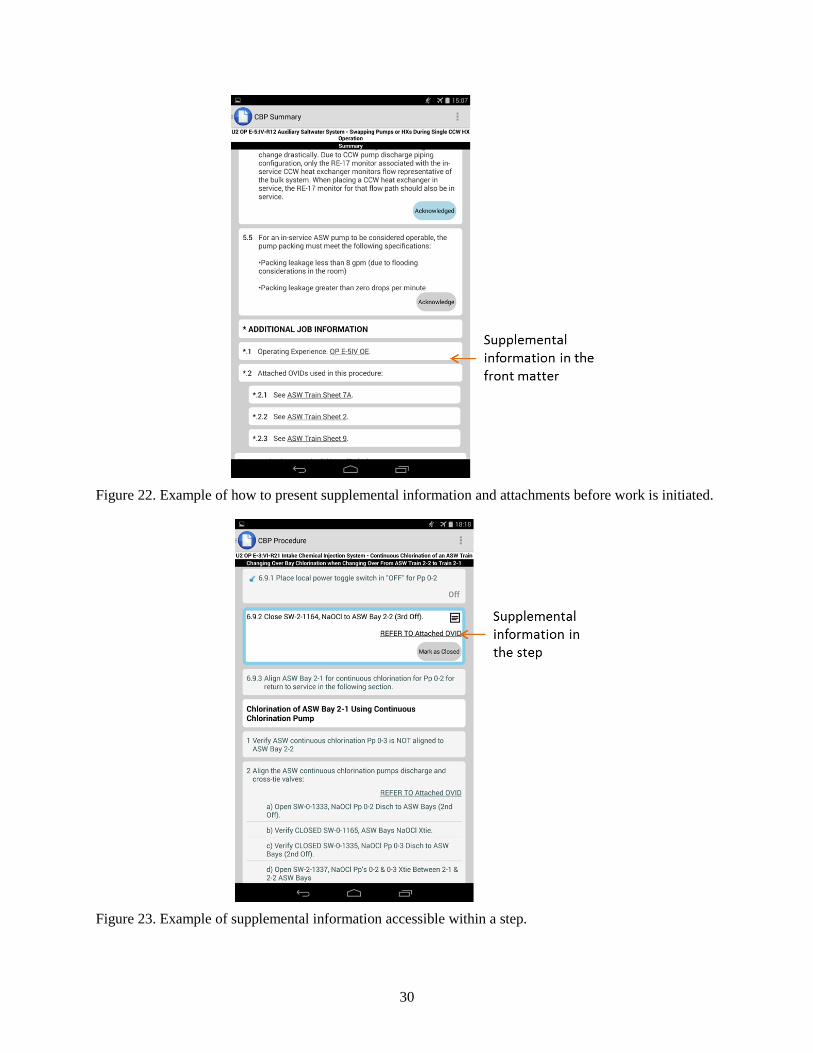
In the CBP system this type of information should be easily accessible when needed. This does not mean that all information should be presented at all time since this would risk the worker becoming overloaded with information which will distract the worker from the task at hand. Supplemental information and other information such as graphs, tables, and figures should be incorporated/accessible via the specific procedure step they relate to. Figure 22 depicts how supplemental information and attachments may be presented and made available to the worker before the task is initiated (e.g., to be used during walkdown). Figure 23 shows an example of how supplemental information could be made accessible from within a specific procedure step. By linking to the supplemental information rather than always display it reduce the risk of information overload and cluttering. It also allows the worker to decide how much additional information he/she needs to successfully complete the task. An inexperienced worker might want more information than a more experienced worker.
30
Figure 22. Example of how to present supplemental information and attachments before work is initiated.
Figure 23. Example of supplemental information accessible within a step.
31
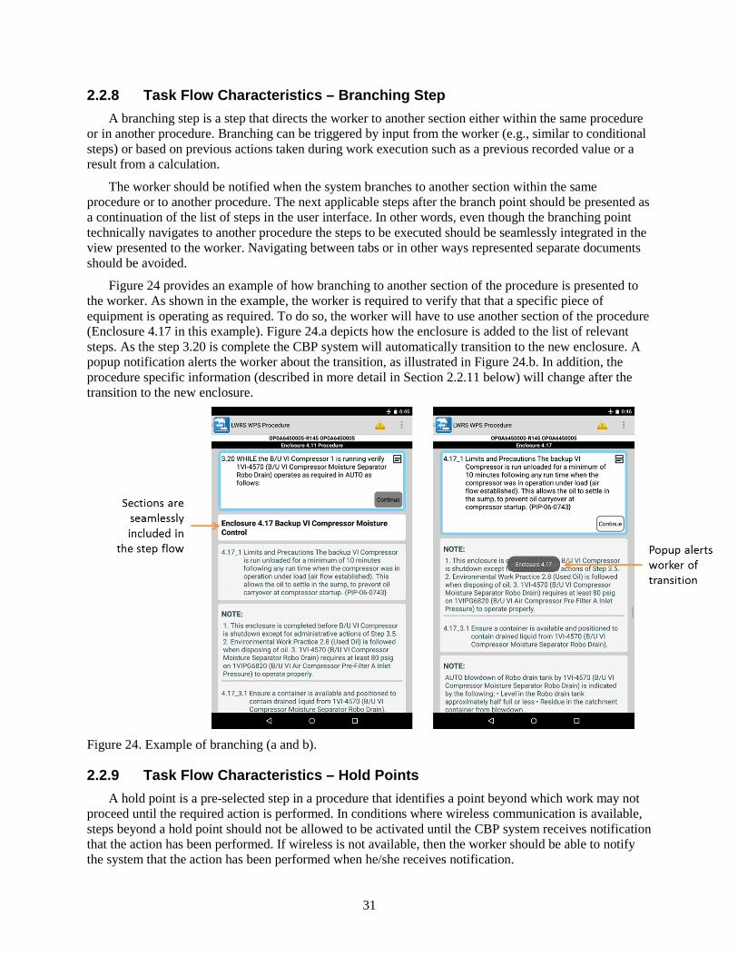
2.2.8 Task Flow Characteristics – Branching Step A branching step is a step that directs the worker to another section either within the same procedure
or in another procedure. Branching can be triggered by input from the worker (e.g., similar to conditional steps) or based on previous actions taken during work execution such as a previous recorded value or a result from a calculation.
The worker should be notified when the system branches to another section within the same procedure or to another procedure. The next applicable steps after the branch point should be presented as a continuation of the list of steps in the user interface. In other words, even though the branching point technically navigates to another procedure the steps to be executed should be seamlessly integrated in the view presented to the worker. Navigating between tabs or in other ways represented separate documents should be avoided.
Figure 24 provides an example of how branching to another section of the procedure is presented to the worker. As shown in the example, the worker is required to verify that that a specific piece of equipment is operating as required. To do so, the worker will have to use another section of the procedure (Enclosure 4.17 in this example). Figure 24.a depicts how the enclosure is added to the list of relevant steps. As the step 3.20 is complete the CBP system will automatically transition to the new enclosure. A popup notification alerts the worker about the transition, as illustrated in Figure 24.b. In addition, the procedure specific information (described in more detail in Section 2.2.11 below) will change after the transition to the new enclosure.
Figure 24. Example of branching (a and b).
2.2.9 Task Flow Characteristics – Hold Points A hold point is a pre-selected step in a procedure that identifies a point beyond which work may not
proceed until the required action is performed. In conditions where wireless communication is available, steps beyond a hold point should not be allowed to be activated until the CBP system receives notification that the action has been performed. If wireless is not available, then the worker should be able to notify the system that the action has been performed when he/she receives notification.
32
2.2.10 Task Flow Characteristics – Hierarchical Step Structure Traditionally, all procedure steps, except for bulleted substeps, are numbered. The main purpose of a
step numbering schemes is to differentiate between steps and substeps of the procedure by providing identifiable differences from one level or step level to the next.
When the procedure system guides the worker through the applicable path of the task execution based on decision made by the worker the step numbering scheme becomes less relevant. This is especially true for tasks which requires the worker to branch back and forth within one larger procedure or where multiple procedures are needed to complete the task. When a system seamlessly navigates the worker between sections the step numbers will no longer be as important for navigation.
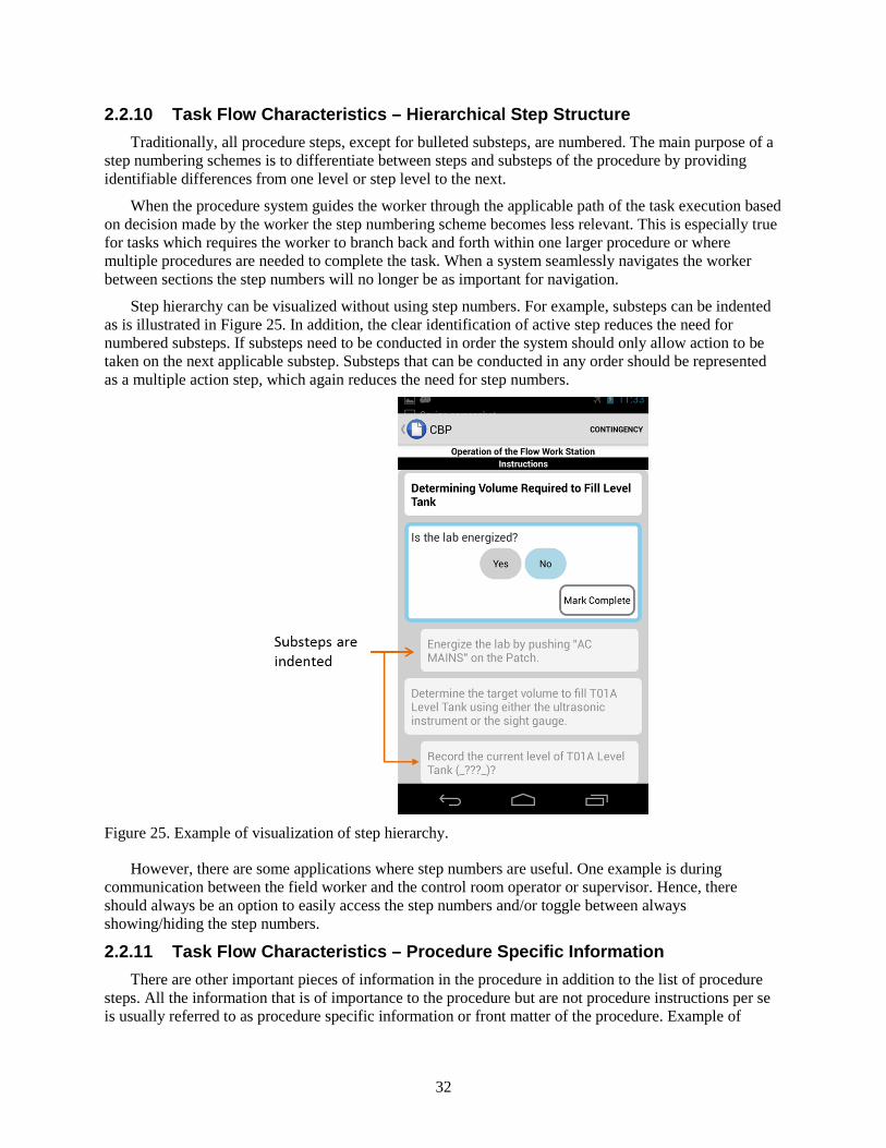
Step hierarchy can be visualized without using step numbers. For example, substeps can be indented as is illustrated in Figure 25. In addition, the clear identification of active step reduces the need for numbered substeps. If substeps need to be conducted in order the system should only allow action to be taken on the next applicable substep. Substeps that can be conducted in any order should be represented as a multiple action step, which again reduces the need for step numbers.
Figure 25. Example of visualization of step hierarchy.
However, there are some applications where step numbers are useful. One example is during communication between the field worker and the control room operator or supervisor. Hence, there should always be an option to easily access the step numbers and/or toggle between always showing/hiding the step numbers.
2.2.11 Task Flow Characteristics – Procedure Specific Information There are other important pieces of information in the procedure in addition to the list of procedure
steps. All the information that is of importance to the procedure but are not procedure instructions per se is usually referred to as procedure specific information or front matter of the procedure. Example of
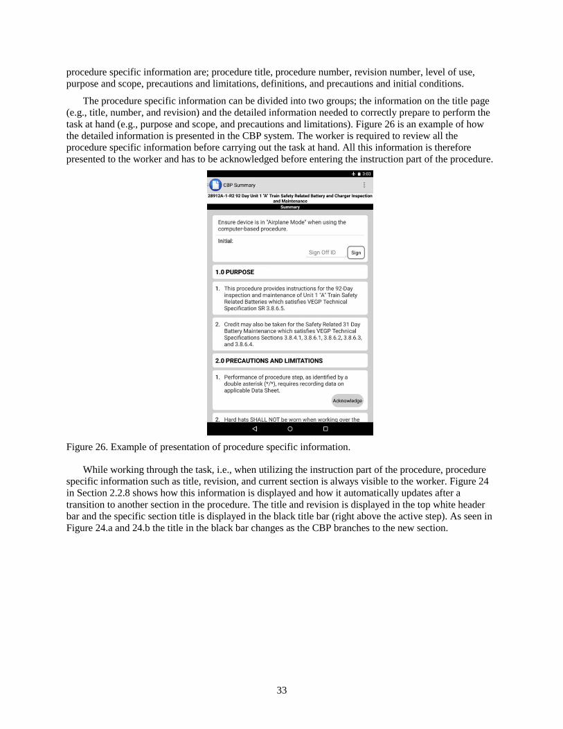
33
procedure specific information are; procedure title, procedure number, revision number, level of use, purpose and scope, precautions and limitations, definitions, and precautions and initial conditions.
The procedure specific information can be divided into two groups; the information on the title page (e.g., title, number, and revision) and the detailed information needed to correctly prepare to perform the task at hand (e.g., purpose and scope, and precautions and limitations). Figure 26 is an example of how the detailed information is presented in the CBP system. The worker is required to review all the procedure specific information before carrying out the task at hand. All this information is therefore presented to the worker and has to be acknowledged before entering the instruction part of the procedure.
Figure 26. Example of presentation of procedure specific information.
While working through the task, i.e., when utilizing the instruction part of the procedure, procedure specific information such as title, revision, and current section is always visible to the worker. Figure 24 in Section 2.2.8 shows how this information is displayed and how it automatically updates after a transition to another section in the procedure. The title and revision is displayed in the top white header bar and the specific section title is displayed in the black title bar (right above the active step). As seen in Figure 24.a and 24.b the title in the black bar changes as the CBP branches to the new section.
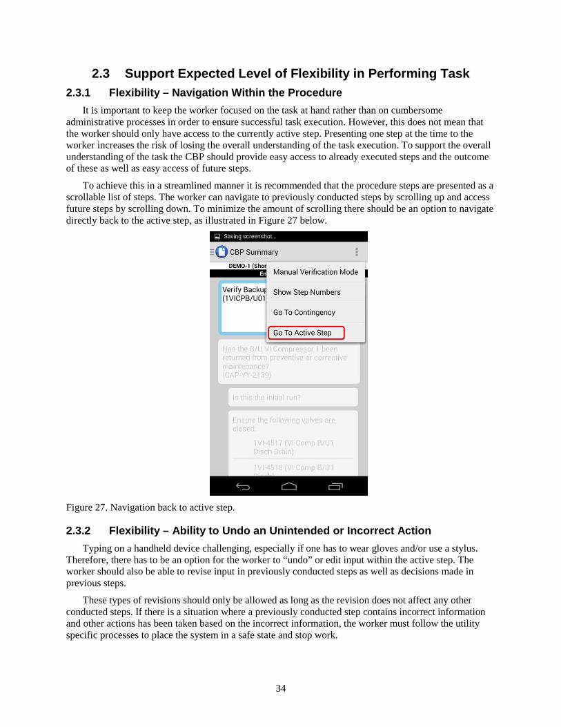
34
2.3 Support Expected Level of Flexibility in Performing Task 2.3.1 Flexibility – Navigation Within the Procedure
It is important to keep the worker focused on the task at hand rather than on cumbersome administrative processes in order to ensure successful task execution. However, this does not mean that the worker should only have access to the currently active step. Presenting one step at the time to the worker increases the risk of losing the overall understanding of the task execution. To support the overall understanding of the task the CBP should provide easy access to already executed steps and the outcome of these as well as easy access of future steps.
To achieve this in a streamlined manner it is recommended that the procedure steps are presented as a scrollable list of steps. The worker can navigate to previously conducted steps by scrolling up and access future steps by scrolling down. To minimize the amount of scrolling there should be an option to navigate directly back to the active step, as illustrated in Figure 27 below.
Figure 27. Navigation back to active step.
2.3.2 Flexibility – Ability to Undo an Unintended or Incorrect Action Typing on a handheld device challenging, especially if one has to wear gloves and/or use a stylus.
Therefore, there has to be an option for the worker to “undo” or edit input within the active step. The worker should also be able to revise input in previously conducted steps as well as decisions made in previous steps.
These types of revisions should only be allowed as long as the revision does not affect any other conducted steps. If there is a situation where a previously conducted step contains incorrect information and other actions has been taken based on the incorrect information, the worker must follow the utility specific processes to place the system in a safe state and stop work.
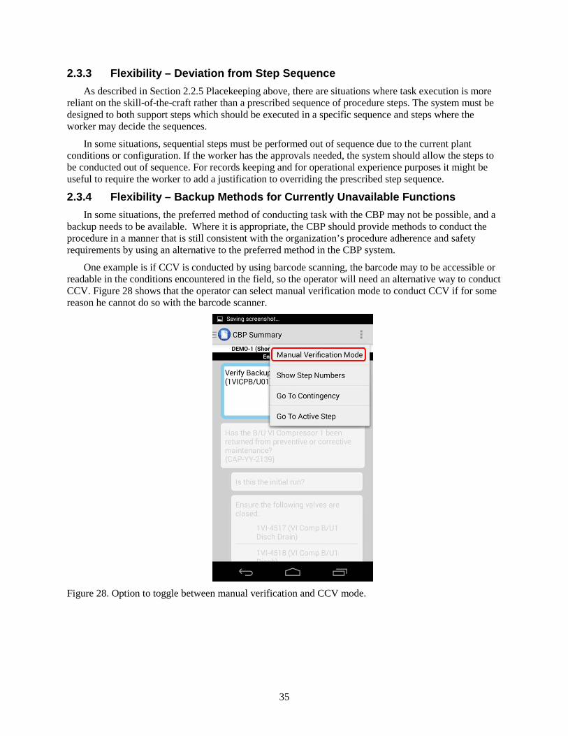
35
2.3.3 Flexibility – Deviation from Step Sequence As described in Section 2.2.5 Placekeeping above, there are situations where task execution is more
reliant on the skill-of-the-craft rather than a prescribed sequence of procedure steps. The system must be designed to both support steps which should be executed in a specific sequence and steps where the worker may decide the sequences.
In some situations, sequential steps must be performed out of sequence due to the current plant conditions or configuration. If the worker has the approvals needed, the system should allow the steps to be conducted out of sequence. For records keeping and for operational experience purposes it might be useful to require the worker to add a justification to overriding the prescribed step sequence.
2.3.4 Flexibility – Backup Methods for Currently Unavailable Functions In some situations, the preferred method of conducting task with the CBP may not be possible, and a
backup needs to be available. Where it is appropriate, the CBP should provide methods to conduct the procedure in a manner that is still consistent with the organization’s procedure adherence and safety requirements by using an alternative to the preferred method in the CBP system.
One example is if CCV is conducted by using barcode scanning, the barcode may to be accessible or readable in the conditions encountered in the field, so the operator will need an alternative way to conduct CCV. Figure 28 shows that the operator can select manual verification mode to conduct CCV if for some reason he cannot do so with the barcode scanner.
Figure 28. Option to toggle between manual verification and CCV mode.
36
2.4 Guide Worker through Logical Sequence of the Procedure The dynamic nature of CBPs allows for a system that can guide the worker through the logical
sequence or path of the procedure based on user input, previous actions or decisions, or plant status information. When the necessary information is available to the CBP, the procedure system should evaluate step logic. This shifts the burden of the evaluation to the system rather than the field worker. The procedure system can either prompt the worker of the relevant conditions needed to make a decision, or acquire the conditions from previous actions/decisions in the procedure or from a plant information database.
The CBP should guide the worker to the next applicable step when the current action step is completed. Steps that are not applicable do not necessarily need to be visible to the worker at all times. Many procedures contain instructions to operate an entire system, and a given task may only require a section or two, while the rest are not applicable. Only presenting the applicable steps allows the worker to focus on the task at hand rather than how to navigate the procedure. However, the not applicable steps must be easily accessible when requested or needed.
One of the main design principles for CBPs is the principle of simplified step logic. Simplified step logic is achieved by removing complexity from step instruction by presenting conditional steps in a simplified manner. A conditional step in a procedure is a step that is based on plant conditions or a combination of conditions to be satisfied prior to the performance of an action. Writing conditional statements that are clear and concise in every situation is hard. Some situations require nested conditional statements, which add a cognitive burden on the worker as he/she navigates through the statement(s) to decide the correct path forward.
The main way that step logic can be simplified for the worker is to present conditional statements such as IF/THEN, WHEN/THEN, AND, and OR as simple questions. For example, the statement “IF starting pump A THEN perform the following…” would be presented a “What pump do you want to start; Pump A or Pump B?” Depending on the answer the procedure will take the worker to either a step with the actions needed to start the pump A or the step with the actions needed to start pump B.
The section of steps that are not applicable based on the decision will automatically be marked as such. Hence, the worker can focus on the actual task at hand and not be burden by deciding which steps are not applicable and marking them as such. This minimizes the risk of the worker incorrectly identifying whether steps are applicable or not.
2.4.1 Simplified Step Logic – Conditional Statement Figure 29 and 30 below both illustrate how simplified step logic can be implemented to handle
conditional statements. In the example shown in Figure 29 the CBP system will update the view of the next applicable step based on the answer to the conditional statement. This approach allows the worker to review the different paths forward before finalizing the decision (i.e., marking the conditional statement as complete). In the example below, the worker would have to energize the laboratory in the case it is not already energized.
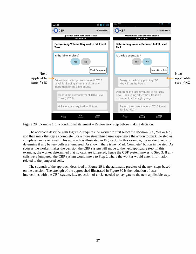
37
Figure 29. Example 1 of a conditional statement – Review next step before making decision.
The approach describe with Figure 29 requires the worker to first select the decision (i.e., Yes or No) and then mark the step as complete. For a more streamlined user experience the action to mark the step as complete can be removed. This approach is illustrated in Figure 30. In this example, the worker needs to determine if any battery cells are jumpered. As shown, there is no “Mark Complete” button in the step. As soon as the worker makes the decision the CBP system will move to the next applicable step. In this example, the worker determined that no cells are jumpered, hence the CBP system moves to Step 3. If any cells were jumpered, the CBP system would move to Step 2 where the worker would enter information related to the jumpered cells.
The strength of the approach described in Figure 29 is the automatic preview of the next steps based on the decision. The strength of the approached illustrated in Figure 30 is the reduction of user interactions with the CBP system, i.e., reduction of clicks needed to navigate to the next applicable step.
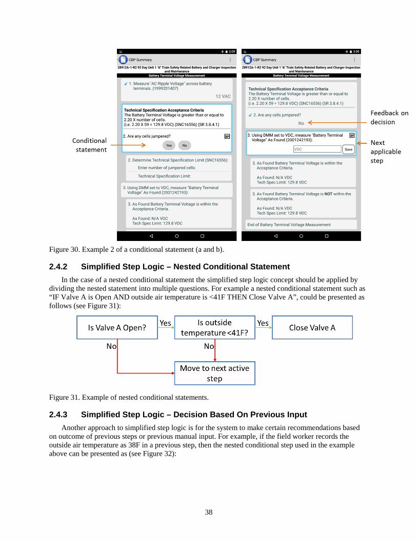
38
Figure 30. Example 2 of a conditional statement (a and b).
2.4.2 Simplified Step Logic – Nested Conditional Statement In the case of a nested conditional statement the simplified step logic concept should be applied by
dividing the nested statement into multiple questions. For example a nested conditional statement such as “IF Valve A is Open AND outside air temperature is <41F THEN Close Valve A”, could be presented as follows (see Figure 31):
Figure 31. Example of nested conditional statements.
2.4.3 Simplified Step Logic – Decision Based On Previous Input Another approach to simplified step logic is for the system to make certain recommendations based
on outcome of previous steps or previous manual input. For example, if the field worker records the outside air temperature as 38F in a previous step, then the nested conditional step used in the example above can be presented as (see Figure 32):
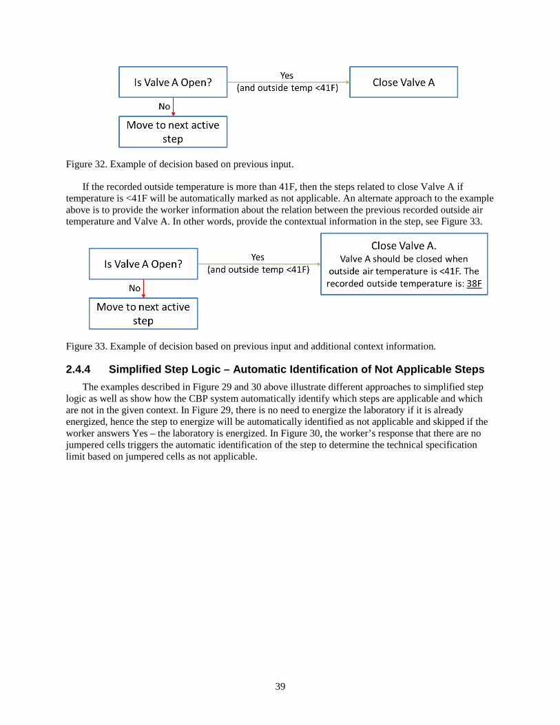
39
Figure 32. Example of decision based on previous input.
If the recorded outside temperature is more than 41F, then the steps related to close Valve A if temperature is <41F will be automatically marked as not applicable. An alternate approach to the example above is to provide the worker information about the relation between the previous recorded outside air temperature and Valve A. In other words, provide the contextual information in the step, see Figure 33.
Figure 33. Example of decision based on previous input and additional context information.
2.4.4 Simplified Step Logic – Automatic Identification of Not Applicable Steps The examples described in Figure 29 and 30 above illustrate different approaches to simplified step
logic as well as show how the CBP system automatically identify which steps are applicable and which are not in the given context. In Figure 29, there is no need to energize the laboratory if it is already energized, hence the step to energize will be automatically identified as not applicable and skipped if the worker answers Yes – the laboratory is energized. In Figure 30, the worker’s response that there are no jumpered cells triggers the automatic identification of the step to determine the technical specification limit based on jumpered cells as not applicable.
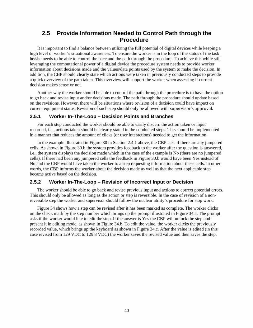
40
2.5 Provide Information Needed to Control Path through the Procedure
It is important to find a balance between utilizing the full potential of digital devices while keeping a high level of worker’s situational awareness. To ensure the worker is in the loop of the status of the task he/she needs to be able to control the pace and the path through the procedure. To achieve this while still leveraging the computational power of a digital device the procedure system needs to provide worker information about decisions made and the values/data points used by the system to make the decision. In addition, the CBP should clearly state which actions were taken in previously conducted steps to provide a quick overview of the path taken. This overview will support the worker when assessing if current decision makes sense or not.
Another way the worker should be able to control the path through the procedure is to have the option to go back and revise input and/or decisions made. The path through the procedure should update based on the revisions. However, there will be situations where revision of a decision could have impact on current equipment status. Revision of such step should only be allowed with supervisor’s approval.
2.5.1 Worker In-The-Loop – Decision Points and Branches For each step conducted the worker should be able to easily discern the action taken or input
recorded, i.e., actions taken should be clearly stated in the conducted steps. This should be implemented in a manner that reduces the amount of clicks (or user interactions) needed to get the information.
In the example illustrated in Figure 30 in Section 2.4.1 above, the CBP asks if there are any jumpered cells. As shown in Figure 30.b the system provides feedback to the worker after the question is answered, i.e., the system displays the decision made which in the case of the example is No (there are no jumpered cells). If there had been any jumpered cells the feedback in Figure 30.b would have been Yes instead of No and the CBP would have taken the worker to a step requesting information about these cells. In other words, the CBP informs the worker about the decision made as well as that the next applicable step became active based on the decision.
2.5.2 Worker In-The-Loop – Revision of Incorrect Input or Decision The worker should be able to go back and revise previous input and actions to correct potential errors.
This should only be allowed as long as the action or step is reversible. In the case of revision of a non-reversible step the worker and supervisor should follow the nuclear utility’s procedure for stop work.
Figure 34 shows how a step can be revised after it has been marked as complete. The worker clicks on the check mark by the step number which brings up the prompt illustrated in Figure 34.a. The prompt asks if the worker would like to edit the step. If the answer is Yes the CBP will unlock the step and present it in editing mode, as shown in Figure 34.b. To edit the value, the worker clicks the previously recorded value, which brings up the keyboard as shown in Figure 34.c. After the value is edited (in this case revised from 129 VDC to 129.8 VDC) the worker saves the revised value and then saves the step.
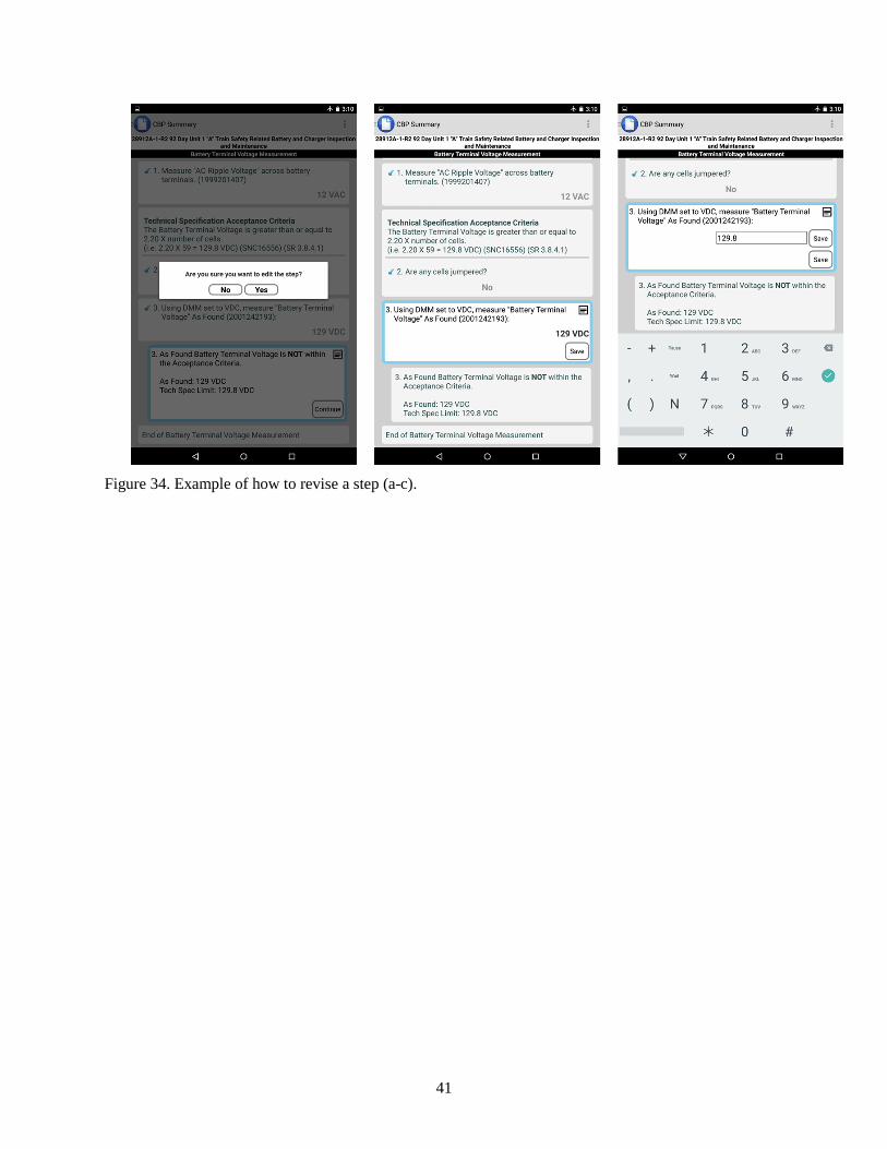
41
Figure 34. Example of how to revise a step (a-c).
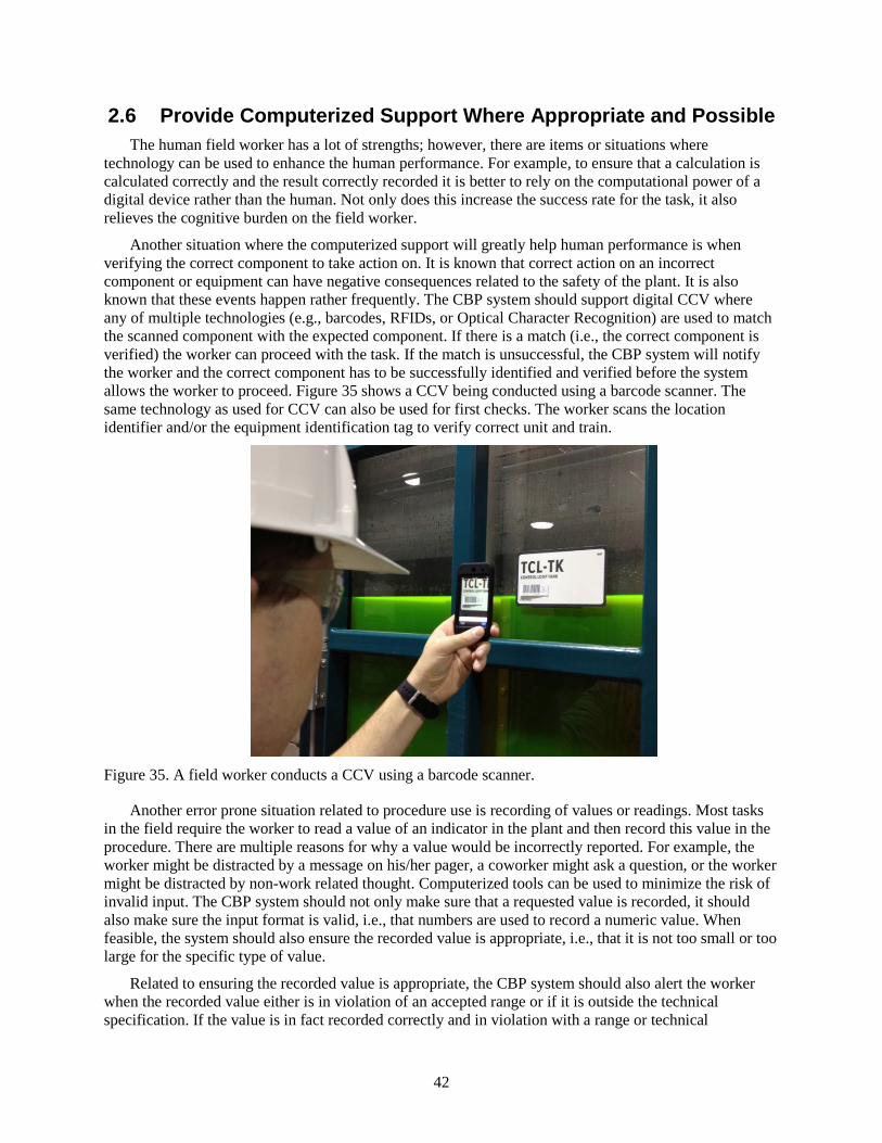
42
2.6 Provide Computerized Support Where Appropriate and Possible The human field worker has a lot of strengths; however, there are items or situations where
technology can be used to enhance the human performance. For example, to ensure that a calculation is calculated correctly and the result correctly recorded it is better to rely on the computational power of a digital device rather than the human. Not only does this increase the success rate for the task, it also relieves the cognitive burden on the field worker.
Another situation where the computerized support will greatly help human performance is when verifying the correct component to take action on. It is known that correct action on an incorrect component or equipment can have negative consequences related to the safety of the plant. It is also known that these events happen rather frequently. The CBP system should support digital CCV where any of multiple technologies (e.g., barcodes, RFIDs, or Optical Character Recognition) are used to match the scanned component with the expected component. If there is a match (i.e., the correct component is verified) the worker can proceed with the task. If the match is unsuccessful, the CBP system will notify the worker and the correct component has to be successfully identified and verified before the system allows the worker to proceed. Figure 35 shows a CCV being conducted using a barcode scanner. The same technology as used for CCV can also be used for first checks. The worker scans the location identifier and/or the equipment identification tag to verify correct unit and train.
Figure 35. A field worker conducts a CCV using a barcode scanner.
Another error prone situation related to procedure use is recording of values or readings. Most tasks in the field require the worker to read a value of an indicator in the plant and then record this value in the procedure. There are multiple reasons for why a value would be incorrectly reported. For example, the worker might be distracted by a message on his/her pager, a coworker might ask a question, or the worker might be distracted by non-work related thought. Computerized tools can be used to minimize the risk of invalid input. The CBP system should not only make sure that a requested value is recorded, it should also make sure the input format is valid, i.e., that numbers are used to record a numeric value. When feasible, the system should also ensure the recorded value is appropriate, i.e., that it is not too small or too large for the specific type of value.
Related to ensuring the recorded value is appropriate, the CBP system should also alert the worker when the recorded value either is in violation of an accepted range or if it is outside the technical specification. If the value is in fact recorded correctly and in violation with a range or technical
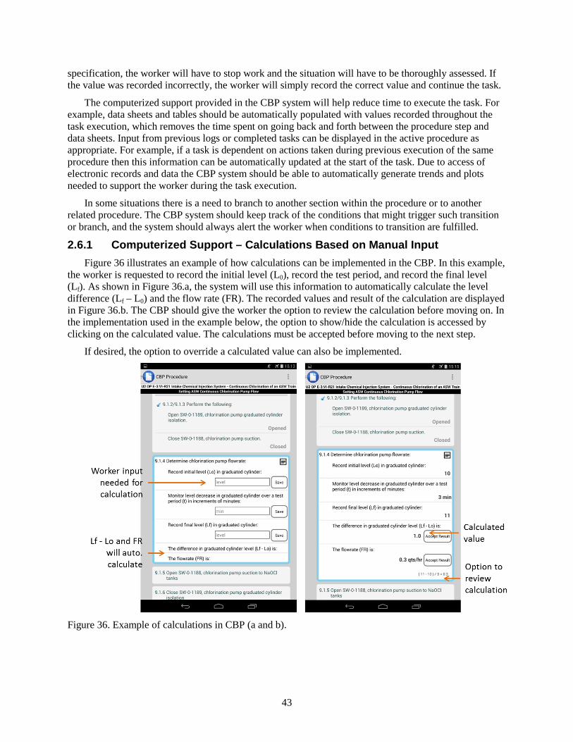
43
specification, the worker will have to stop work and the situation will have to be thoroughly assessed. If the value was recorded incorrectly, the worker will simply record the correct value and continue the task.
The computerized support provided in the CBP system will help reduce time to execute the task. For example, data sheets and tables should be automatically populated with values recorded throughout the task execution, which removes the time spent on going back and forth between the procedure step and data sheets. Input from previous logs or completed tasks can be displayed in the active procedure as appropriate. For example, if a task is dependent on actions taken during previous execution of the same procedure then this information can be automatically updated at the start of the task. Due to access of electronic records and data the CBP system should be able to automatically generate trends and plots needed to support the worker during the task execution.
In some situations there is a need to branch to another section within the procedure or to another related procedure. The CBP system should keep track of the conditions that might trigger such transition or branch, and the system should always alert the worker when conditions to transition are fulfilled.
2.6.1 Computerized Support – Calculations Based on Manual Input Figure 36 illustrates an example of how calculations can be implemented in the CBP. In this example,
the worker is requested to record the initial level (L0), record the test period, and record the final level (Lf). As shown in Figure 36.a, the system will use this information to automatically calculate the level difference (Lf – L0) and the flow rate (FR). The recorded values and result of the calculation are displayed in Figure 36.b. The CBP should give the worker the option to review the calculation before moving on. In the implementation used in the example below, the option to show/hide the calculation is accessed by clicking on the calculated value. The calculations must be accepted before moving to the next step.
If desired, the option to override a calculated value can also be implemented.
Figure 36. Example of calculations in CBP (a and b).
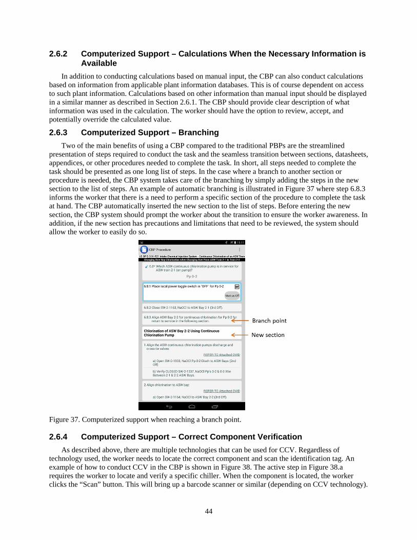
44
2.6.2 Computerized Support – Calculations When the Necessary Information is Available
In addition to conducting calculations based on manual input, the CBP can also conduct calculations based on information from applicable plant information databases. This is of course dependent on access to such plant information. Calculations based on other information than manual input should be displayed in a similar manner as described in Section 2.6.1. The CBP should provide clear description of what information was used in the calculation. The worker should have the option to review, accept, and potentially override the calculated value.
2.6.3 Computerized Support – Branching Two of the main benefits of using a CBP compared to the traditional PBPs are the streamlined
presentation of steps required to conduct the task and the seamless transition between sections, datasheets, appendices, or other procedures needed to complete the task. In short, all steps needed to complete the task should be presented as one long list of steps. In the case where a branch to another section or procedure is needed, the CBP system takes care of the branching by simply adding the steps in the new section to the list of steps. An example of automatic branching is illustrated in Figure 37 where step 6.8.3 informs the worker that there is a need to perform a specific section of the procedure to complete the task at hand. The CBP automatically inserted the new section to the list of steps. Before entering the new section, the CBP system should prompt the worker about the transition to ensure the worker awareness. In addition, if the new section has precautions and limitations that need to be reviewed, the system should allow the worker to easily do so.
Figure 37. Computerized support when reaching a branch point.
2.6.4 Computerized Support – Correct Component Verification As described above, there are multiple technologies that can be used for CCV. Regardless of
technology used, the worker needs to locate the correct component and scan the identification tag. An example of how to conduct CCV in the CBP is shown in Figure 38. The active step in Figure 38.a requires the worker to locate and verify a specific chiller. When the component is located, the worker clicks the “Scan” button. This will bring up a barcode scanner or similar (depending on CCV technology).
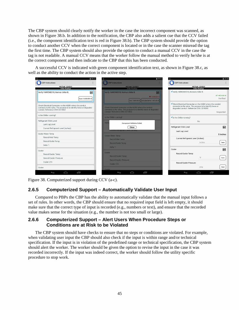
45
The CBP system should clearly notify the worker in the case the incorrect component was scanned, as shown in Figure 38.b. In addition to the notification, the CBP also adds a salient cue that the CCV failed (i.e., the component identification text is red in Figure 38.b). The CBP system should provide the option to conduct another CCV when the correct component is located or in the case the scanner misread the tag the first time. The CBP system should also provide the option to conduct a manual CCV in the case the tag is not readable. A manual CCV means that the worker follow the manual method to verify he/she is at the correct component and then indicate to the CBP that this has been conducted.
A successful CCV is indicated with green component identification text, as shown in Figure 38.c, as well as the ability to conduct the action in the active step.
Figure 38. Computerized support during CCV (a-c).
2.6.5 Computerized Support – Automatically Validate User Input Compared to PBPs the CBP has the ability to automatically validate that the manual input follows a
set of rules. In other words, the CBP should ensure that no required input field is left empty, it should make sure that the correct type of input is recorded (e.g., numbers or text), and ensure that the recorded value makes sense for the situation (e.g., the number is not too small or large).
2.6.6 Computerized Support – Alert Users When Procedure Steps or Conditions are at Risk to be Violated
The CBP system should have checks to ensure that no steps or conditions are violated. For example, when validating user input the CBP should also check if the input is within range and/or technical specification. If the input is in violation of the predefined range or technical specification, the CBP system should alert the worker. The worker should be given the option to revise the input in the case it was recorded incorrectly. If the input was indeed correct, the worker should follow the utility specific procedure to stop work.
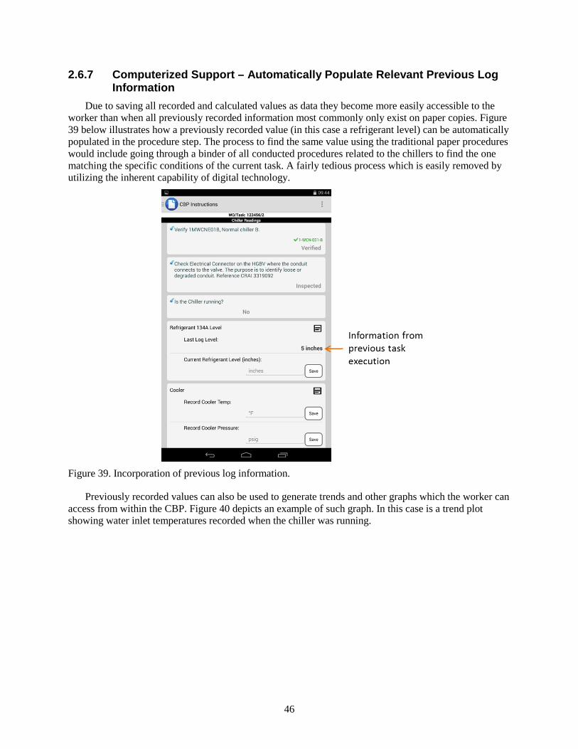
46
2.6.7 Computerized Support – Automatically Populate Relevant Previous Log Information
Due to saving all recorded and calculated values as data they become more easily accessible to the worker than when all previously recorded information most commonly only exist on paper copies. Figure 39 below illustrates how a previously recorded value (in this case a refrigerant level) can be automatically populated in the procedure step. The process to find the same value using the traditional paper procedures would include going through a binder of all conducted procedures related to the chillers to find the one matching the specific conditions of the current task. A fairly tedious process which is easily removed by utilizing the inherent capability of digital technology.
Figure 39. Incorporation of previous log information.
Previously recorded values can also be used to generate trends and other graphs which the worker can access from within the CBP. Figure 40 depicts an example of such graph. In this case is a trend plot showing water inlet temperatures recorded when the chiller was running.
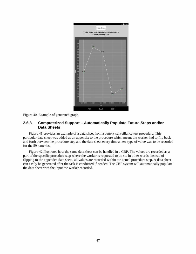
47
Figure 40. Example of generated graph.
2.6.8 Computerized Support – Automatically Populate Future Steps and/or Data Sheets
Figure 41 provides an example of a data sheet from a battery surveillance test procedure. This particular data sheet was added as an appendix to the procedure which meant the worker had to flip back and forth between the procedure step and the data sheet every time a new type of value was to be recorded for the 59 batteries.
Figure 42 illustrates how the same data sheet can be handled in a CBP. The values are recorded as a part of the specific procedure step where the worker is requested to do so. In other words, instead of flipping to the appended data sheet, all values are recorded within the actual procedure step. A data sheet can easily be generated after the task is conducted if needed. The CBP system will automatically populate the data sheet with the input the worker recorded.

48
Figure 41. Example of traditional data sheet.
4
Figure 42. Example of an integrated data sheet.
49
2.7 Include Functionality that Improves Communication Efficient communication between field workers, supervisors, and the control room is important in
order to get the work done correctly and on time. With the use of a CBP on a mobile device some communications can be automated. This automation will decrease the completion time of the task at hand.
Shift turnover can become more efficient in the fact that all the data is stored and passed electronically. This allows workers at the end of a shift to upload and release the work that has been recorded during their shift on any given work order or procedure. The new shift should have immediate access to the data and be able to pick up where the other shift left off. The immediate access of the previous shift’s work reduces the need to track down the paper work and reduces the time it takes to ensure the new shift has all information needed.
The ability to automatically provide task status to the supervisor will increase the efficiency of the communication between the worker in the field and the supervisor. The supervisor does not need to contact (and hence interrupt) the worker to get a status update. This real time status updates, or near real time if full wireless coverage is not available, will provide the supervisor a better understanding of the work status and allow him/her to optimize the scheduling of resources.
The shared work status between the supervisor and worker will also improve the communication in the case the worker has a question or request for the supervisor. The time spent on explaining the situation will be reduced by the fact that they both share a common understanding of the task progression up to the point of the communication.
The CBP system provides the worker the ability to provide more context to the communication than only a verbal description. The communication can be enhanced by using photos and videos. The ability for the supervisor to actually see the situation reduces the time the worker would need to describe the problem. Thus allowing the problem to be resolved in a shorter time frame.
In addition, the work status information shared via the CBP system provides a benefit to the communication between the control room operators and field workers. Automatic notification triggers within the system should notify the relevant parties when conditions are met for a hand-off between the control room and the field. The system will notify the field worker when work can be initiated in the field as well as notifying the control room when the field worker reaches a point where the control room needs to take action. This reduces the time needed for hand offs between the control room and the field. Also, the time between scheduled tasks can be removed due to the more rapid hand-off when a task is complete.
2.7.1 Communication – Shift Turnover The CBP should be used as a tool to enhance the communication during the shift turnover. The
worker who is coming off the shift checks in the work orders he/she has been working on during the shift. The worker who is coming on shift checks out the task on his/her device. The workers used the checked out version of the procedure to guide the turnover. All the decisions and input made by the first worker are saved and the worker coming on shift can pick up right where the first worker left off.
2.7.2 Communication – Field Worker and Supervisor As the worker progresses through the procedure, the CBP system is sending status updates to the
server, which can be displayed to the supervisor on a status board or dashboard. The supervisor can use this information to get an overview of the progression of all tasks scheduled for the shift. If the worker needs the supervisor’s input on a potential issue, the worker can contact the supervisor via the CBP system. As they work through the issue both the supervisor and worker have access to the same information (e.g., previously conducted steps, active step, and shared videos). This reduces the need for either the worker to come back into the office or for the supervisor to go out to the work location.
50
2.7.3 Communication – Control Room Operators and Field Worker Control room operators could have access to a similar dashboard as the supervisor and hence be able
to see the status of relevant tasks. If the worker encounters an issue where the control room’s input is needed, the worker and control room operator will be able to share information about the situation.
The CBP system also automated the communication between the control room operator and the field worker when they share tasks. If the control room operator performs a task that requires actions from the field worker the CBP system would notify the worker in the field when he/she can start work. The system would also ensure the worker is qualified to conduct the task as well as provide the worker with the latest revision of the procedure. When the actions in the field are completed the CBP will notify the operator that the task can be resumed in the control room.
51
2.8 Provide a Method to Review and Save Records The utility is required to retain records of all tasks conducted at the plant. As noted previously, one of
the benefits with a CBP system is that all information, decisions, and notes are saved as data. This allows for easy access to data from previously conducted tasks as well as allows for the data to be retained in a manner that suits the utility specific requirements. In other words, the system should be able to provide the data in a format that can be easily applied to a desired template and create a readable document.
The need for archiving paper copies of the procedures will hopefully be reduced as electronic archiving becomes more and more acceptable in the industry. However, until the industry reaches this point of acceptance there is still a need to consider archiving of paper copies.
2.8.1 Records – Paper Archives The data collected through the task execution can be used to automatically populate a template that
follows the utility specific format required for a nuclear record. This document can then be printed to paper and archived.
2.8.2 Records – Electronic Archives Electronic archives should include all the data gathered during the task execution. The electronic copy
does not have to be stored in the same format as the paper copy. Instead, the data should be stored in appropriate database(s) to allow easy access to whoever needs it. Upon request, the appropriate data should be accessed to create requested documents or trends. This allows for multiple uses (by multiple users) of the recorded data without duplicating the raw data points. In other words, the same archived data points can be used to automatically populate a new procedure as well as being used by an engineer to trend performance of a certain piece of equipment.
52
3. REFERENCES Electric Power Research Institute. (2015). Human Factros Guidance for Control Room and Digital
Human-System Interface Design and Modification - Guidelines for Planning, Specification, Design, Licensing, Implementation, Training, Operation, and Maintenance for Operating Plants and New Builds. TR-3002004310. Palo Alto, CA: Electric Power Research Institute.
Electric Power Research Institute. (2015). Improving the Execution and Productivity of Maintenance with Electronic Work Packages. TR-3002005363. Palo Alto, CA: Electric Power Research Institute.
IEEE. (2011, Sept. 22). IEEE Guide for Human Factors Applications of Computerized Operating Procedure Systems (COPS) at Nuclear Power Generating Stations and Other Nuclear Facilities. IEEE Std 1786-2011, 1-38. doi:10.1109/IEEESTD.2011.6029264
Le Blanc, K., & Oxstrand, J. (2012). A Model of Operator Interaction with Field Procedures: Insights for Computer-Based Procedures. Proceedings of The 56rd Annual Meeting of the Human Factors and Ergonomics Society. 56, pp. 2031-2035. Boston: Sage Publications. doi:10.1177/1071181312561424
Le Blanc, K., Oxstrand, J., & Waicosky, T. (2012). Requirements for Computer-Based Procedures for Nuclear Power Plant Field Operators - Results from a Qualitative Study. 3rd International Conference on NPP Life Management for Long Term Operations (IAEA PLiM 2012). Salt Lake City: IAEA.
O'Hara, J., Higgins, J. C., Stubler, W. F., & Kramer, J. (2000). Computer-Based Procedure Systems: Technical Basis and Human Factors Review Guidance, NUREG/CR-6634. Washington, D.C.: U.S. Nuclear Regulatory Commission.
Oxstrand, J., & Bly, A. (2016). Computer-Based Procedures for Field Workers - FY16 Research Activities. Idaho Falls: Idaho National Laboratory (INL/EXT-16-39984).
Oxstrand, J., & Le Blanc, K. (2012). Computer-Based Procedures for Field Workers in Nuclear Power Plants: Development of a Model of Procedure Usage and Identification of Requirements. Idaho Falls: Idaho National Laboratory (INL/EXT-12-25671).
Oxstrand, J., & Le Blanc, K. (2014). Computer-Based Procedures for Field Workers – Identified Benefits. Idaho Falls: Idaho National Laboratory (INL/EXT-14-33011).
Oxstrand, J., Al Rashdan, A., Le Blanc, K., Bly, A., & Agarwal, V. (2015). Light Water Reactor Sustainability Program Automated Work Package Prototype: Initial Design, Development, and Evaluation. Idaho Falls: Idaho National Laboratory (INL/EXT-15-35825).
Oxstrand, J., Le Blanc, K., & Bly, A. (2013). Computer-Based Procedures for Field Workers: Results From Three Evaluation Studies. Idaho Falls: Idaho National Laboratory (INL/EXT-13-30183).
Oxstrand, J., Le Blanc, K., Bly, A., Medema, H., & Hill, W. (2015). Computer-Based Procedures for Field Workers - Result and Insights from Three Usability and Interface Design Evaluations. Idaho Falls: Idaho National Laboratory (INL/EXT-15-36658).

53
Appendix A
Model of Procedure Usage
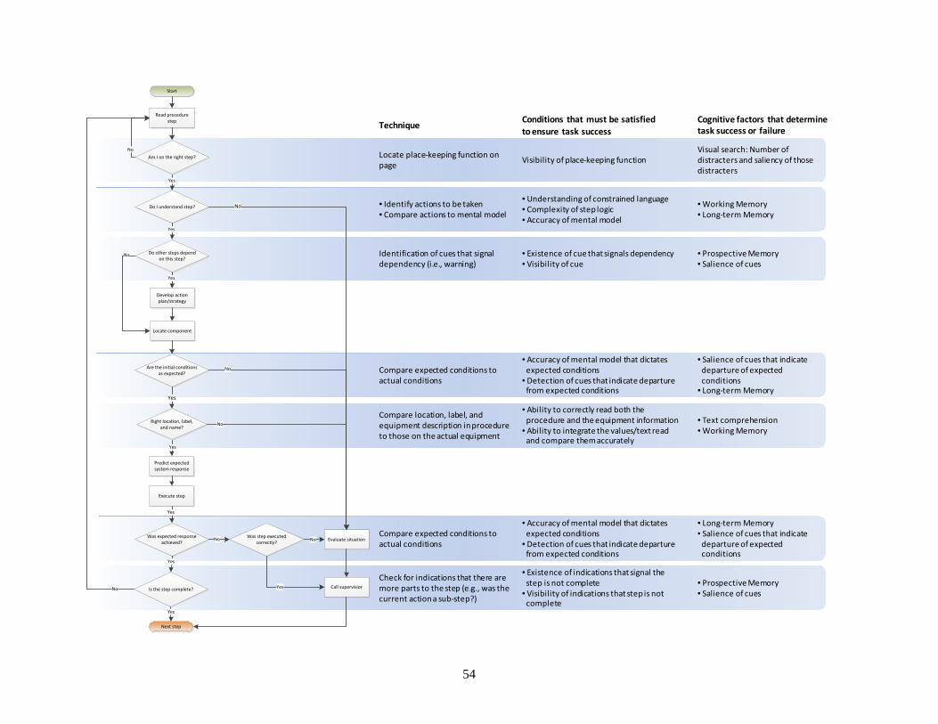
54
Locate place-keeping function on page Visibility of place-keeping function
Visual search: Number of distracters and saliency of those distracters
• Identify actions to be taken• Compare actions to mental model
• Understanding of constrained language• Complexity of step logic• Accuracy of mental model
• Working Memory• Long-term Memory
Compare expected conditions to actual conditions
• Accuracy of mental model that dictates expected conditions
• Detection of cues that indicate departure from expected conditions
• Salience of cues that indicate departure of expected conditions
• Long-term Memory
Compare location, label, and equipment description in procedure to those on the actual equipment
• Ability to correctly read both the procedure and the equipment information
• Ability to integrate the values/text readand compare them accurately
• Text comprehension• Working Memory
Compare expected conditions to actual conditions
• Accuracy of mental model that dictates expected conditions
• Detection of cues that indicate departure from expected conditions
• Long-term Memory• Salience of cues that indicate
departure of expected conditions
Check for indications that there are more parts to the step (e.g., was the current action a sub-step?)
• Existence of indications that signal the step is not complete
• Visibility of indications that step is not complete
• Prospective Memory• Salience of cues
Identification of cues that signal dependency (i.e., warning)
• Existence of cue that signals dependency• Visibility of cue
• Prospective Memory• Salience of cues
Technique Cognitive factors that determine task success or failure
Conditions that must be satisfied to ensure task success
Start
Read procedure step
Do I understand step?
Do other steps depend on this step?
Develop action plan/strategy
Locate component
Are the initial conditions as expected?
Predict expected system response
Execute step
Was step executed correctly?
Was expected response achieved?
Yes
Next step
Yes
Evaluate situationNo
Call supervisior
No
No
No
Yes
Yes
Yes
No
Yes
Right location, label, and name?
Am I on the right step?No
Is the step complete?
Yes
No Yes
No
Yes

55
Appendix B
Minimum Requirements for Computer-Based Procedures
56
Appendix B Minimum Requirements for Computer-Based Procedures
The following requirements were published 2012 by Le Blanc, Oxstrand, and Waicosky in the article Requirements for Computer Based-Procedures for Nuclear Power Plant Field Operators – Results from a Qualitative Study. Minimum set of requirements for CBPs intended to address some of the challenges that field workers have identified associated with their current use of paper-based procedures: (1) CBPs should guide workers through the logical sequence of the procedure. The CBPs should be
designed so that they automatically take the workers through the specified procedure path based on initial conditions and worker input.
(2) CBPs should ease the burden of place-keeping for the worker. CBPs should keep track of where the worker is in the procedure, should mark steps as completed, and should highlight the current step.
(3) CBPs should make the action steps more distinguishable from information gathering steps. CBPs should use some method to differentiate steps for which a worker must actually manipulate the plant versus when he must simply check a condition or value.
(4) CBPs should alert the worker to dependencies in steps more visibly. Typically, the worker has to rely on previous experience or on a caution or warning in order to identify the situations in which he needs to read ahead in the steps. CBPs should alert the worker when he reaches a step with dependencies, rather than relying on him to read ahead (or remember from previous experience) to detect the dependency. Additionally, if a CBP system has access to real-time plant data the system should alert the worker when plant status changes in a manner that affects the worker’s task.
(5) CBPs should ease the burden of correct component verification (CCV) for the worker. CBPs should employ some method to automate CCV (e.g., include barcode scanning or text recognition functionality).
(6) CBPs should ease the identification and support assessment of the expected initial conditions. Some method of illustrating the expected initial conditions in a simple and easy to understand manner should be available to the worker through the CBPs. For example a schematic or piping and instrument diagram of the relevant equipment could be available on-demand.
(7) CBPs should ease the identification and support assessment of the expected plant and equipment response. Some method of illustrating the expected equipment and plant response in a simple and easy to understand manner should be available to the worker through the CBPs. For example a schematic or piping and instrument diagram of the relevant equipment could be available on-demand.
(8) CBPs should include functionality that improves communication. In the event that a worker encounters a situation that he needs to contact a supervisor to resolve, he needs to be able to efficiently and accurately describe the problem. Tools such as texting, capturing photographs and streaming video have all been identified as highly desirable to have built into any device that display CBPs.
Additionally, CBPs must also be designed so that they are consistent with existing guidance and human factors engineering principles. Thus CBPs for field workers must also meet the following specific requirements: CBPs should be designed so that the worker controls the procedure pace. CBPs should make calculations when the necessary information is available. The CBP system should alert users when procedure steps or conditions have been violated.
57
The CBP system should alert users when conditions require transitioning to another procedure. When the necessary information is available to the CBP, the procedure system should evaluate step
logic. The CBP system should be designed so that it is easy for the user to “undo” an unintended or
incorrect action (an error of commission). The CBP should provide dynamic, context-sensitive information. The CBP system should automatically monitor users. The CBP system should allow the worker to look ahead and back in the procedure. The CBP system should provide seamless navigational transitions to other active procedure(s), to
branches and transitions in the same procedures, and to supplemental information required by the procedure.
The CBP system should indicate when there are multiple active procedures. The CBP system should provide flexibility in the amount of information/level of detail where
appropriate. The CBPs should provide identification of active procedure information (title, revision number, etc.). The CBP should provide high-level information related to procedure goals. The CBP system should provide identification of procedure system status. The CBP should provide indication of user input requirements. The CBP system should provide user support (e.g., a help function).