Embed Size (px)
Citation preview

PN 2631943 September 2006, Rev 1, 6/07 © 2007 Fluke Corporation. All rights reserved. Printed in USA. All product names are trademarks of their respective companies.
NetToolTM
Series II Inline Network Tester
Getting Started Guide

LIMITED WARRANTY AND LIMITATION OF LIABILITY
Fluke Networks mainframe products will be free from defects in material and workmanship for one year from the date of purchase. Parts, accessories, product repairs and services are warranted for 90 days, unless otherwise stated. Ni-Cad, Ni-MH and Li-Ion batteries, cables or other peripherals are all considered parts or accessories. This warranty does not cover damage from accident, neglect, misuse, alteration, contamination, or abnormal condi-tions of operation or handling. Resellers are not author-ized to extend any other warranty on Fluke Networks’ behalf. To obtain service during the warranty period, contact your nearest Fluke Networks authorized service center to obtain return authorization information, then send your defective product to that Service Center with a description of the problem.
THIS WARRANTY IS YOUR ONLY REMEDY. NO OTHER WARRANTIES, SUCH AS FITNESS FOR A PARTICULAR PURPOSE, ARE EXPRESSED OR IMPLIED. FLUKE NET-WORKS IS NOT LIABLE FOR ANY SPECIAL, INDIRECT, INCIDENTAL OR CONSEQUENTIAL DAMAGES OR LOSSES, ARISING FROM ANY CAUSE OR THEORY. Since some states or countries do not allow the exclu-sion or limitation of an implied warranty or of inci-dental or consequential damages, this limitation of liability may not apply to you.
4/04
Fluke Networks PO Box 777 Everett, WA 98206-0777 USA

i
Table of Contents
Title Page
About This Guide ........................................................ 1 NetTool Product Features .......................................... 2 Safety and Operational Information........................ 3 Power Supply............................................................... 4 Using the Batteries and AC Adapter .................. 4 Using PoE Power................................................... 6 Front View ................................................................... 7 Left Side View.............................................................. 10 Navigation Buttons..................................................... 11 Scrolling.................................................................. 11 Paging Up and Down........................................... 11 Closing the Current Screen.................................. 11 Accessing Configuration Screens ........................ 11 Menus .......................................................................... 12 Network Diagram................................................. 12 Main Menu............................................................ 14 Setting User Preferences ............................................ 15 Setting User Preferences ............................................ 15 Connecting the Tester ................................................ 16 Single-Ended Connections................................... 16 Patch Cable Test.............................................. 17 Wiremap.......................................................... 17 Toner................................................................ 18 Inline Connection.................................................. 19 AutoTest....................................................................... 20 Cable Test Results ................................................. 21 Wiremap Test Results ........................................... 21 Service Identification Test Results....................... 22 Device and Network Test Results........................ 22 NetTool
Connect ........................................................ 24 Updating the Software ............................................. 24 Contacting Fluke Networks ....................................... 25

ii

1
NetTool Series II Inline Network Tester
About This Guide
We know that you want to begin using your new NetTool Series II Inline Network Tester right away. This guide provides basic information to help you do just that.
The first section acquaints you with the features of your NetTool Series II Inline Network Tester (hereafter referred to as the tester) and provides quick, easy-to-follow instructions for setting it up. Later sections step you though the basics of connecting the tester, running tests, and viewing results.
For detailed instructions on using your tester, see the Users Manual, which is located on the CD that came with your purchase. And, for the latest news, troubleshooting tips, and service information about your tester, go to www.flukenetworks.com.
2
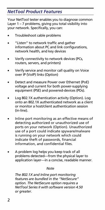
NetTool Product Features
Your NetTool tester enables you to diagnose common Layer 1 – 7 problems, giving you total visibility into your network. Specifically, you can:
• Troubleshoot cable problems
• “Listen” to network traffic and gather information about PC and link configurations, network health, and key devices
• Verify connectivity to network devices (PCs, routers, servers, and printers)
• Verify service and monitor call quality on Voice over IP (VoIP) links (Option)
• Detect and measure Power over Ethernet (PoE) voltage and current for both power-supplying equipment (PSE) and powered-devices (PDs).
• Log 802.1X authentication activity (Option). Log onto an 802.1X authenticated network as a client or monitor a host/client authentication session (in-line).
• Inline port monitoring as an effective means of detecting authorized or unauthorized use of ports on your network (Option). Unauthorized use of a port could indicate spyware/malware is running on your network which could indicate theft of passwords, financial information, and confidential files.
• A problem log helps you keep track of all problems detected—from the physical layer to application layer—in a concise, readable manner.
Note
The 802.1X and Inline port monitoring features are bundled in the “NetSecure” option. The NetSecure option requires a NetTool Series II with software version 4.50 or greater.
3
Registering Your NetTool Tester
Please take the time to register your tester. Registration offers you access to support, training, software, and product updates.
Go to the Fluke Networks website at http://www.flukenetworks.com. Click the Register link and follow the instructions to log in and register your tester online.
Safety and Operational Information
To operate your tester safely, observe the usage and disposal warnings represented by the symbols that are found on your tester. The meanings of these symbols are given in the following table.
International Electrical Symbols
W Warning or Caution: Risk of damage or destruction to equipment or software.
j This equipment not for connection to public communications networks, such as active telephone systems.
~ Do not put products containing circuit boards into the garbage. Dispose of circuits boards in accordance with local regulations.

4
Power Supply
To supply power to your tester, you can use batteries, the optional AC Adapter, or PoE.
Using the Batteries and AC Adapter
The tester uses four alkaline batteries (supplied) or four rechargeable NiMH batteries (optional).
To install the batteries, remove the yellow boot to access the battery compartment. Open the door and insert the batteries, as shown in the following illustration:
1
2
ekd01f.eps
5
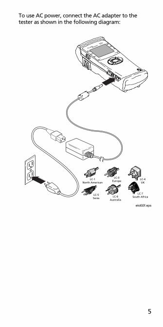
To use AC power, connect the AC adapter to the tester as shown in the following diagram:
LC-1North American
LC-3Europe
LC-4UK
LC-5Swiss
LC-6Australia
LC-7South Africa
ekd02f.eps

6
Using PoE Power
If the tester is connected to PSE and has negotiated power from the device, it uses power supplied by the PSE.
Note
You must use the left RJ-45 jack to connect the tester to a PoE switch.
IEEE 802.3af or Ciscopre-af PoE switch
ekd03f.eps
The tester first attempts to pass PoE power through to a PD. If such a device is not attached, the tester draws power from the attached PoE switch.
The PoE LED lights blue to indicate that power is being drawn from the PSE or that PoE power is being drawn inline.

7
Front View
1
2
3
48
7
6
9
5
ekd04f.eps

8
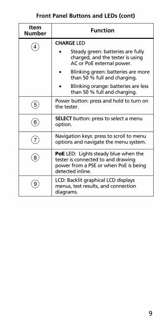
Front Panel Buttons and LEDs
Item Number Function
A Link LED for the left and right RJs
• White: 1000 MB connection.
• Blue: 100 MB connection.
• Green: 10 MB connection.
B Collision/Error LED for the left and right RJs
• Yellow: collisions are occurring.
• Red: errors are being detected.
C Utilization LED for the left and right RJs
• Green: utilization levels are below 50 %.
• Yellow: utilization levels are between 50 % and 90 %.
• Red: utilization levels are higher than 90 %.
9
Front Panel Buttons and LEDs (cont)
Item Number Function
D CHARGE LED
• Steady green: batteries are fully charged, and the tester is using AC or PoE external power.
• Blinking green: batteries are more than 50 % full and charging.
• Blinking orange: batteries are less than 50 % full and charging.
E Power button: press and hold to turn on the tester.
F SELECT button: press to select a menu option.
G Navigation keys: press to scroll to menu options and navigate the menu system.
H PoE LED: Lights steady blue when the tester is connected to and drawing power from a PSE or when PoE is being detected inline.
I LCD: Backlit graphical LCD displays menus, test results, and connection diagrams.
10
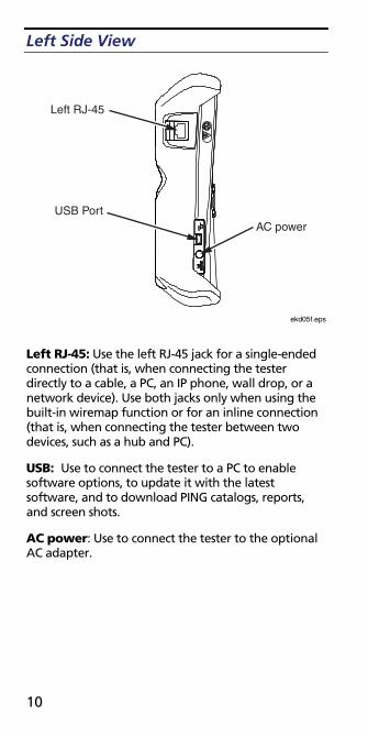
Left Side View
Left RJ-45
USB PortAC power
ekd05f.eps
Left RJ-45: Use the left RJ-45 jack for a single-ended connection (that is, when connecting the tester directly to a cable, a PC, an IP phone, wall drop, or a network device). Use both jacks only when using the built-in wiremap function or for an inline connection (that is, when connecting the tester between two devices, such as a hub and PC).
USB: Use to connect the tester to a PC to enable software options, to update it with the latest software, and to download PING catalogs, reports, and screen shots.
AC power: Use to connect the tester to the optional AC adapter.
11
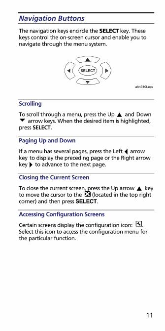
Navigation Buttons
The navigation keys encircle the SELECT key. These keys control the on-screen cursor and enable you to navigate through the menu system.
SELECT
ahn310f.eps
Scrolling
To scroll through a menu, press the Up and Down arrow keys. When the desired item is highlighted,
press SELECT.
Paging Up and Down
If a menu has several pages, press the Left arrow key to display the preceding page or the Right arrow key to advance to the next page.
Closing the Current Screen
To close the current screen, press the Up arrow key to move the cursor to the (located in the top right corner) and then press SELECT.
Accessing Configuration Screens
Certain screens display the configuration icon: . Select this icon to access the configuration menu for the particular function.
12
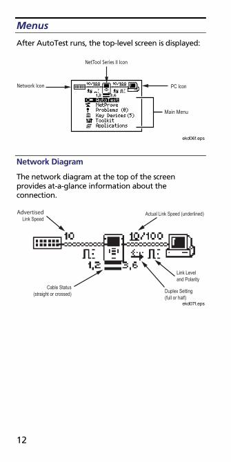
Menus
After AutoTest runs, the top-level screen is displayed:
Network Icon
NetTool Series II Icon
PC Icon�
Main Menu
ekd06f.eps
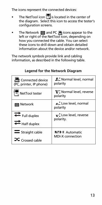
Network Diagram
The network diagram at the top of the screen provides at-a-glance information about the connection.
Actual Link Speed (underlined)
Link Leveland Polarity�
Duplex Setting(full or half)
Cable Status(straight or crossed)
AdvertisedLink Speed
ekd07f.eps
13
The icons represent the connected devices:
The NetTool icon is located in the center of the diagram. Select this icon to access the tester’s configuration screens.
The Network and PC icons appear to the left or right of the NetTool icon, depending on how you connected the cable. You can select these icons to drill down and obtain detailed information about the device and/or network.
The network symbols provide link and cabling information, as described in the following table.
Legend for the Network Diagram
Connected device (PC, printer, IP phone)
Normal level, normal polarity
NetTool tester Normal level, reverse polarity
Network Low level, normal polarity
Full duplex
Half duplex
Low level, reverse polarity.
Straight cable
Crossed cable
Automatic MDI-X connection
14
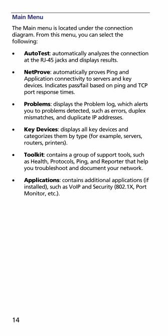
Main Menu
The Main menu is located under the connection diagram. From this menu, you can select the following:
• AutoTest: automatically analyzes the connection at the RJ-45 jacks and displays results.
• NetProve: automatically proves Ping and Application connectivity to servers and key devices. Indicates pass/fail based on ping and TCP port response times.
• Problems: displays the Problem log, which alerts you to problems detected, such as errors, duplex mismatches, and duplicate IP addresses.
• Key Devices: displays all key devices and categorizes them by type (for example, servers, routers, printers).
• Toolkit: contains a group of support tools, such as Health, Protocols, Ping, and Reporter that help you troubleshoot and document your network.
• Applications: contains additional applications (if installed), such as VoIP and Security (802.1X, Port Monitor, etc.).
15
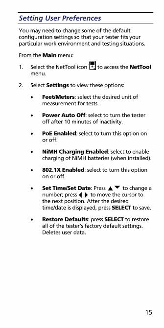
Setting User Preferences
You may need to change some of the default configuration settings so that your tester fits your particular work environment and testing situations.
From the Main menu:
1. Select the NetTool icon to access the NetTool menu.
2. Select Settings to view these options:
• Feet/Meters: select the desired unit of measurement for tests.
• Power Auto Off: select to turn the tester off after 10 minutes of inactivity.
• PoE Enabled: select to turn this option on or off.
• NiMH Charging Enabled: select to enable charging of NiMH batteries (when installed).
• 802.1X Enabled: select to turn this option on or off.
• Set Time/Set Date: Press to change a number; press to move the cursor to the next position. After the desired time/date is displayed, press SELECT to save.
• Restore Defaults: press SELECT to restore all of the tester’s factory default settings. Deletes user data.
16
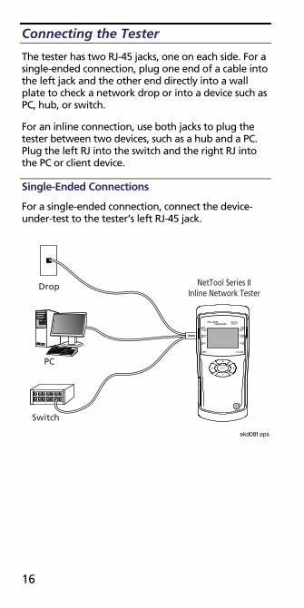
Connecting the Tester
The tester has two RJ-45 jacks, one on each side. For a single-ended connection, plug one end of a cable into the left jack and the other end directly into a wall plate to check a network drop or into a device such as PC, hub, or switch.
For an inline connection, use both jacks to plug the tester between two devices, such as a hub and a PC. Plug the left RJ into the switch and the right RJ into the PC or client device.
Single-Ended Connections
For a single-ended connection, connect the device-under-test to the tester’s left RJ-45 jack.
NetTool Series IIInline Network Tester
Switch
PC
Drop
ekd08f.eps
17
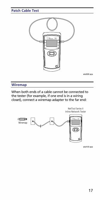
Patch Cable Test
ekd09f.eps
Wiremap
When both ends of a cable cannot be connected to the tester (for example, if one end is in a wiring closet), connect a wiremap adapter to the far end:
Wiremap
NetTool Series IIInline Network Tester
ekd10f.eps

18
Toner
Note
To access the Toner menu, click (the NetTool icon).
200
PRO
BE
200
PRO
BE
IntelliToneProbe
NetTool Series IIInline Network Tester
ekd11f.eps

19
Inline Connection
Note
Use the left RJ to connect the tester to the network and the right RJ to connect to a PC or phone.
NetTool Series IIInline Network Tester
Switch
PC
ekd12f.eps

20
AutoTest
When you run AutoTest, the tester searches the RJ-45 connections to determine what it is connected to and then displays results.
To run AutoTest:
1. Connect the NetTool tester as shown in one of the network diagrams presented earlier.
2. Turn on the tester.
The AutoTest screen is displayed:
ahn13s.bmp
3. If a device is connected, turn it on.
4. Press SELECT to start AutoTest.

21
Cable Test Results
After AutoTest ends, select the Spool icon . Then, press SELECT.
The Cable screen displays the length of the cable and indicates whether any opens, shorts, or split pairs are detected.
afq32s.bmp
Wiremap Test Results
After AutoTest ends, select the Wiremap icon . Then press SELECT.
Cable length and pin configurations are displayed, enabling you to verify that individual wires are properly connected and that no opens or shorts are present:
afq34s.bmp
22
Service Identification Test Results
After AutoTest ends, the tester displays the type of service that is active on the jack:
• Telco
• Ethernet
• No Response: the tester detects the device but the device is not responding
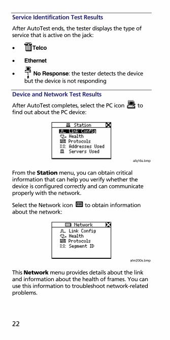
Device and Network Test Results
After AutoTest completes, select the PC icon to find out about the PC device:
afq16s.bmp
From the Station menu, you can obtain critical information that can help you verify whether the device is configured correctly and can communicate properly with the network.
Select the Network icon to obtain information about the network:
ahn200s.bmp
This Network menu provides details about the link and information about the health of frames. You can use this information to troubleshoot network-related problems.
23
NetTool Connect
NetTool Connect is a software utility that is located on the CD-ROM that is packaged with NetTool. This program enables you to do the following:
• Install software updates on your NetTool tester
• Download the tester’s screen captures to your PC
• Download, edit, store, and upload NetProve catalogs
• Download option key information (VoIP, 802.1X, Port Monitor, etc.)
• Manage/download 802.1X authentication setup (only one authentication setup/certificate can be downloaded to a NetTool Series II at a time)
• Manage/download Port Monitor port selection information
• Generate HTML or PDF reports from either live or saved test data
Install NetTool Connect. Then, select Help for instructions on how to use the program.
Updating the Software
From time to time, updates to NetTool software are released. To determine what version is currently installed on your tester:
1. Select the NetTool icon .
2. Select About NetTool...
To find out whether a more recent software version is available, go to www.flukenetworks.com. Find the NetTool product and then click the software link.
If a newer software version is listed, follow the instructions to download the file to your PC. Use the supplied USB cable to connect the tester to your PC.

24
Note
To transfer software update files to your tester, you must have NetTool Connect installed on your PC. You can find this software on the CD that came with your purchase.
Contacting Fluke Networks
www.flukenetworks.com
+1-425-446-4519
• Australia: 61 (2) 8850-3333 or 61(3) 9329 0244
• Beijing: 86 (10) 6512-3435
• Brazil: 11 3044 1277
• Canada: 1-800-363-5853
• Europe: +44-(0) 1923 281 300
• Hong Kong: 852 2721-3228
• Japan: 03-3434-0510
• Korea: 82 2 539-6311
• Singapore: 65 6799-5566
• Taiwan: (886) 2-227-83199
• USA: 1-800-283-5853 • Anywhere in the world: +1-425-446-4519
Visit our website for a complete list of phone numbers.