Embed Size (px)
DESCRIPTION
9 th International Planetary Probe Workshop, Toulouse, June 21 th , 2012. Innovative Visual Navigation Solutions for ESA’s Lunar Lander Mission. Dr. E. Zaunick, D. Fischer, Dr. I. Ahrns, G. Orlando, B. Polle, E. Kervendal. Outline. Mission Overview Mission Scenario Navigation Requirements - PowerPoint PPT Presentation
Citation preview
Lunar Lander Phase B1
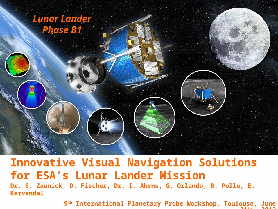
p. 1 9th International Planetary Probe Workshop, Toulouse, June 21th , 2012
Innovative Visual Navigation Solutions for ESA’s Lunar Lander MissionDr. E. Zaunick, D. Fischer, Dr. I. Ahrns, G. Orlando, B. Polle, E. Kervendal
p. 2
Innovative Visual Navigation Solutions for ESA’s Lunar Lander MissionToulouse, June 21th 2012
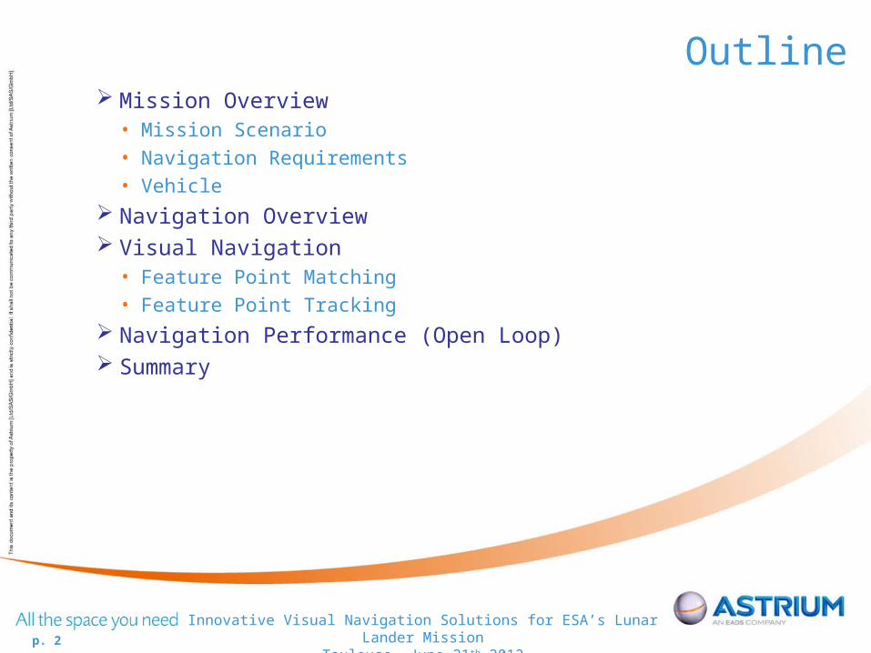
Outline Mission Overview
• Mission Scenario• Navigation Requirements• Vehicle
Navigation Overview Visual Navigation
• Feature Point Matching• Feature Point Tracking
Navigation Performance (Open Loop) Summary

p. 3
Innovative Visual Navigation Solutions for ESA’s Lunar Lander MissionToulouse, June 21th 2012
Mission OverviewLanding Site:
Lunar South pole region• Unique spot to find water-ice (might shelter clues of Earth and solar system)• Permanently, illuminated areas allows continuous operations
Challenging, since:• Chaotic region, made up of many craters, ridges and shadows only
limited area is favourable to autonomous landing in permanently illuminated areas
p. 4
Innovative Visual Navigation Solutions for ESA’s Lunar Lander MissionToulouse, June 21th 2012
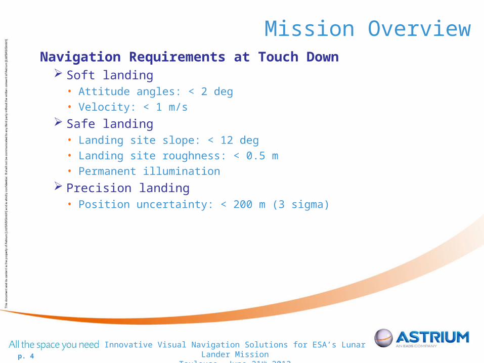
Mission OverviewNavigation Requirements at Touch Down
Soft landing• Attitude angles: < 2 deg• Velocity: < 1 m/s
Safe landing• Landing site slope: < 12 deg• Landing site roughness: < 0.5 m• Permanent illumination
Precision landing• Position uncertainty: < 200 m (3 sigma)
p. 5
Innovative Visual Navigation Solutions for ESA’s Lunar Lander MissionToulouse, June 21th 2012
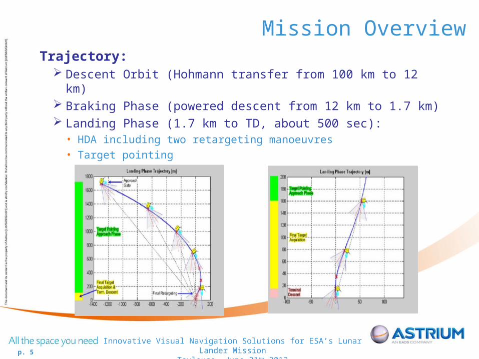
Mission OverviewTrajectory:
Descent Orbit (Hohmann transfer from 100 km to 12 km) Braking Phase (powered descent from 12 km to 1.7 km) Landing Phase (1.7 km to TD, about 500 sec):
• HDA including two retargeting manoeuvres• Target pointing

p. 6
Innovative Visual Navigation Solutions for ESA’s Lunar Lander MissionToulouse, June 21th 2012
Mission OverviewVehicle:
Design: legged lunar lander

p. 7
Innovative Visual Navigation Solutions for ESA’s Lunar Lander MissionToulouse, June 21th 2012
Navigation OverviewSensor Suite:
Navigation camera (NPAL camera) used for:• Feature matching• Feature tracking
IMU Star tracker Distance to ground sensor (DTG) Navigation is filter used for sensor fusion and state estimation, e. g.
• position, velocity, attitude• IMU accelerometer bias

p. 8
Innovative Visual Navigation Solutions for ESA’s Lunar Lander MissionToulouse, June 21th 2012
Navigation Overview
p. 9
Innovative Visual Navigation Solutions for ESA’s Lunar Lander MissionToulouse, June 21th 2012
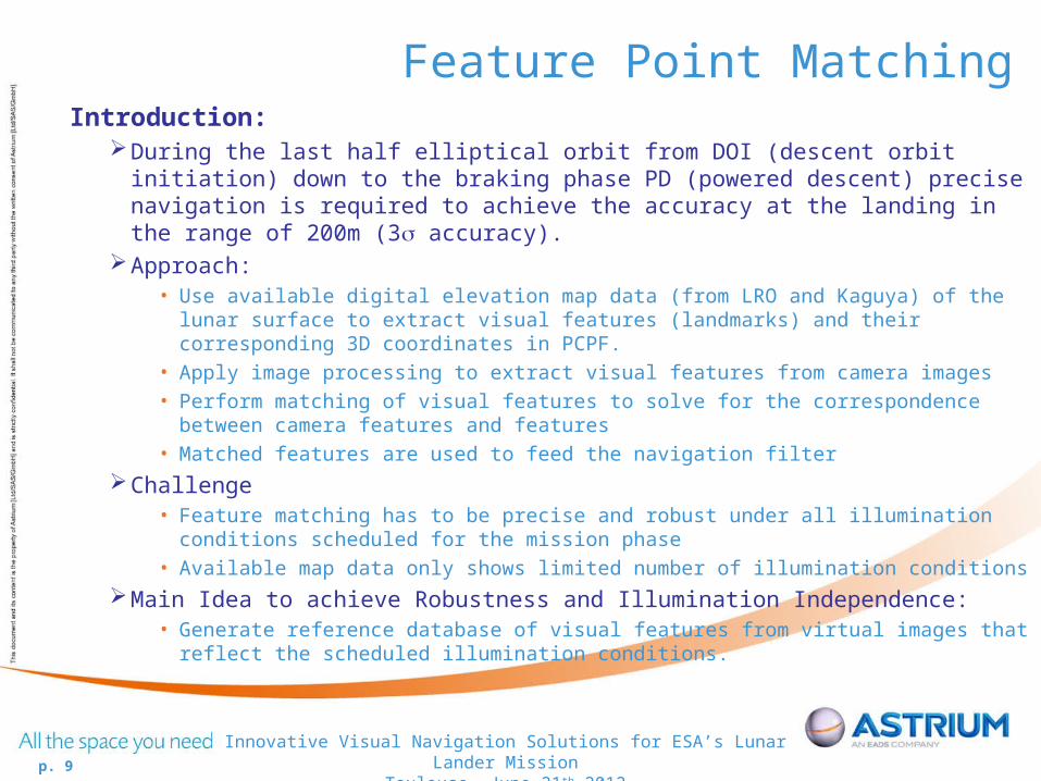
Feature Point MatchingIntroduction:
During the last half elliptical orbit from DOI (descent orbit initiation) down to the braking phase PD (powered descent) precise navigation is required to achieve the accuracy at the landing in the range of 200m (3 accuracy).
Approach:• Use available digital elevation map data (from LRO and Kaguya) of the lunar surface to extract
visual features (landmarks) and their corresponding 3D coordinates in PCPF.
• Apply image processing to extract visual features from camera images
• Perform matching of visual features to solve for the correspondence between camera features and features
• Matched features are used to feed the navigation filter
Challenge• Feature matching has to be precise and robust under all illumination conditions scheduled for
the mission phase
• Available map data only shows limited number of illumination conditions
Main Idea to achieve Robustness and Illumination Independence:• Generate reference database of visual features from virtual images that reflect the scheduled
illumination conditions.
p. 10
Innovative Visual Navigation Solutions for ESA’s Lunar Lander MissionToulouse, June 21th 2012
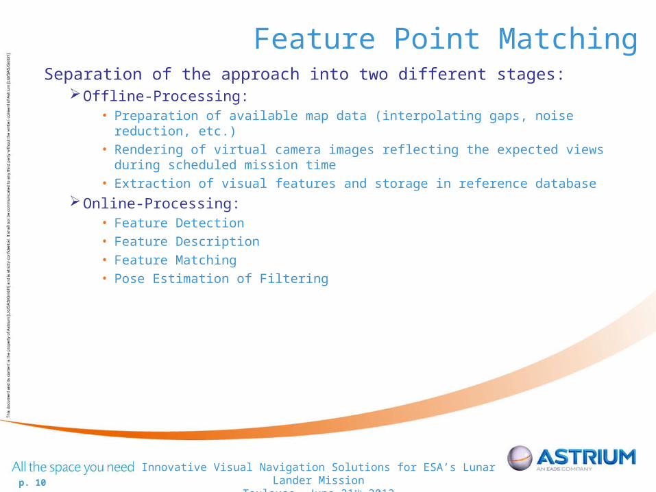
Feature Point MatchingSeparation of the approach into two different stages:
Offline-Processing:• Preparation of available map data (interpolating gaps, noise reduction, etc.)
• Rendering of virtual camera images reflecting the expected views during scheduled mission time
• Extraction of visual features and storage in reference database
Online-Processing:• Feature Detection
• Feature Description
• Feature Matching
• Pose Estimation of Filtering
p. 11
Innovative Visual Navigation Solutions for ESA’s Lunar Lander MissionToulouse, June 21th 2012
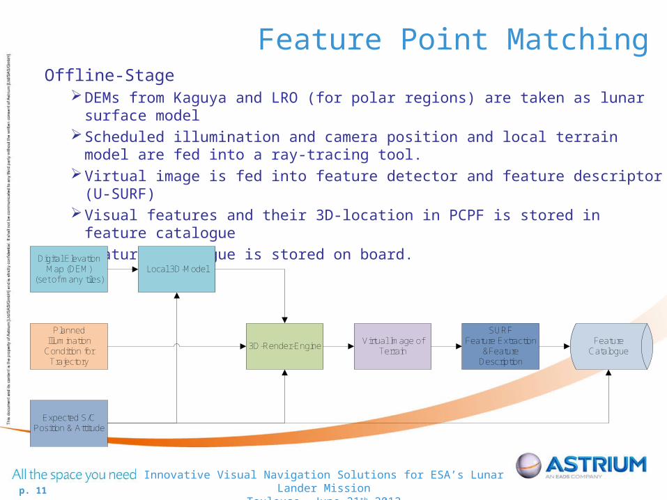
Feature Point MatchingOffline-Stage
DEMs from Kaguya and LRO (for polar regions) are taken as lunar surface modelScheduled illumination and camera position and local terrain model are fed into a ray-
tracing tool.Virtual image is fed into feature detector and feature descriptor (U-SURF)Visual features and their 3D-location in PCPF is stored in feature catalogue Feature catalogue is stored on board.
Digital Elevation Map (DEM)
(set of many tiles)
Planned Illumination
Condition for Trajectory
3D-Render-EngineVirtual Image of
Terrain
SURFFeature Extraction
&Feature Description
Feature Catalogue
Expected S/CPosition & Attitude
Local 3D-Model
p. 12
Innovative Visual Navigation Solutions for ESA’s Lunar Lander MissionToulouse, June 21th 2012
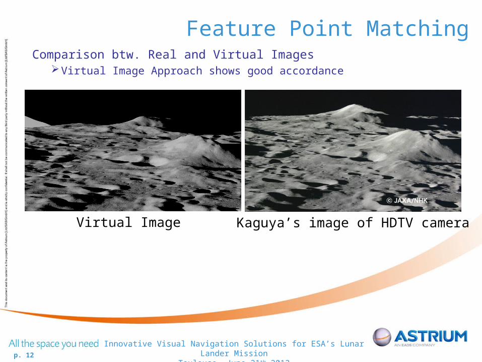
Feature Point MatchingComparison btw. Real and Virtual Images
Virtual Image Approach shows good accordance
Virtual Image Kaguya’s image of HDTV camera
p. 13
Innovative Visual Navigation Solutions for ESA’s Lunar Lander MissionToulouse, June 21th 2012
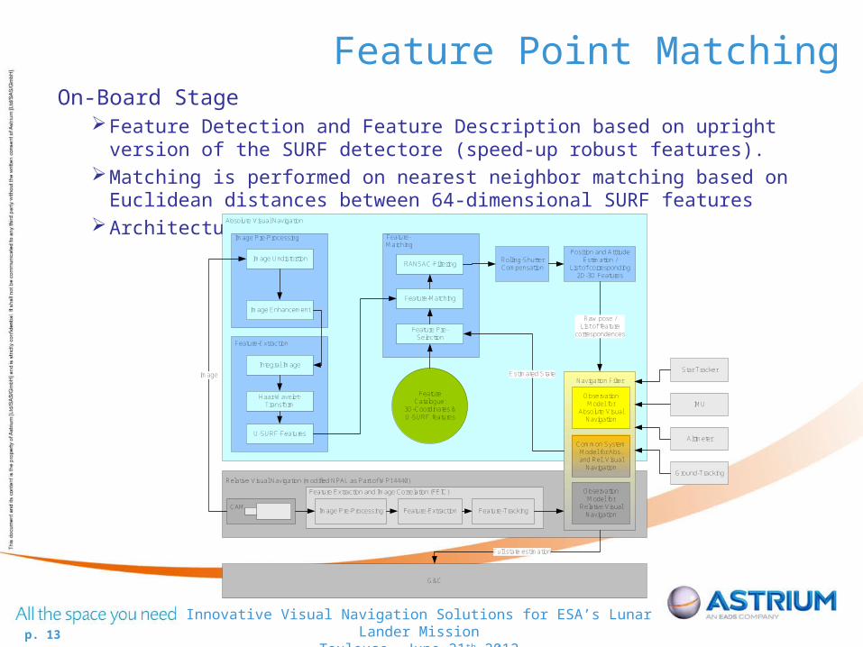
Feature Point MatchingOn-Board Stage
Feature Detection and Feature Description based on upright version of the SURF detectore (speed-up robust features).
Matching is performed on nearest neighbor matching based on Euclidean distances between 64-dimensional SURF features
Architecture:
Relative Visual Navigation (modified NPAL as Part of WP14440)
Absolute Visual Navigation
Image Pre-Processing
CAM
Image Undistortion
Image
Image Enhancement
Feature-Extraction
Integral Image
Haar-Wavelet-Transform
U-SURF-Features
Feature Catalogue:
3D-Coordinates &U-SURF features
Feature-Matching
Navigation Filter
Star Tracker
IMU
Altimeter
Feature Pre-Selection
Ground-Tracking
Feature-Matching
RANSAC-Filtering
Position and Attitude Estimation /
List of corresponding 2D-3D Features
Raw pose /List of feature
correspondences
Feature Extraction and Image Correlation (FEIC)
Image Pre-Processing Feature-Extraction Feature-Tracking
Common System Model for Abs. and Rel. Visual
Navigation
Observation Model for
Absolute Visual Navigation
Observation Model for
Relative Visual Navigation
Estimated State
G&C
Full state estimation
Rolling-ShutterCompensation
p. 14
Innovative Visual Navigation Solutions for ESA’s Lunar Lander MissionToulouse, June 21th 2012
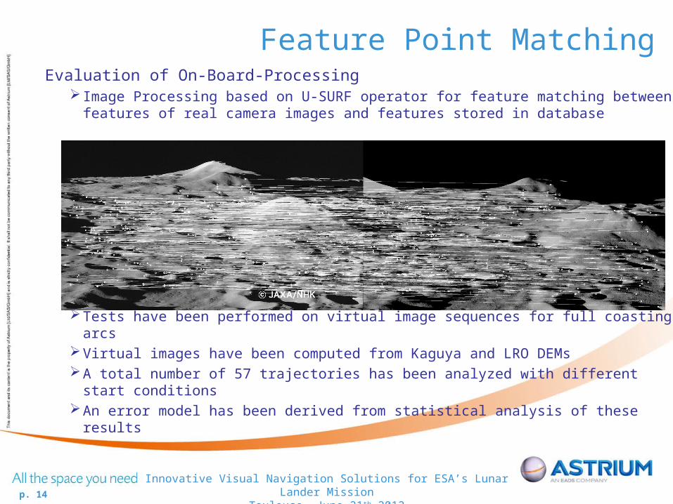
Feature Point MatchingEvaluation of On-Board-Processing
Image Processing based on U-SURF operator for feature matching between features of real camera images and features stored in database
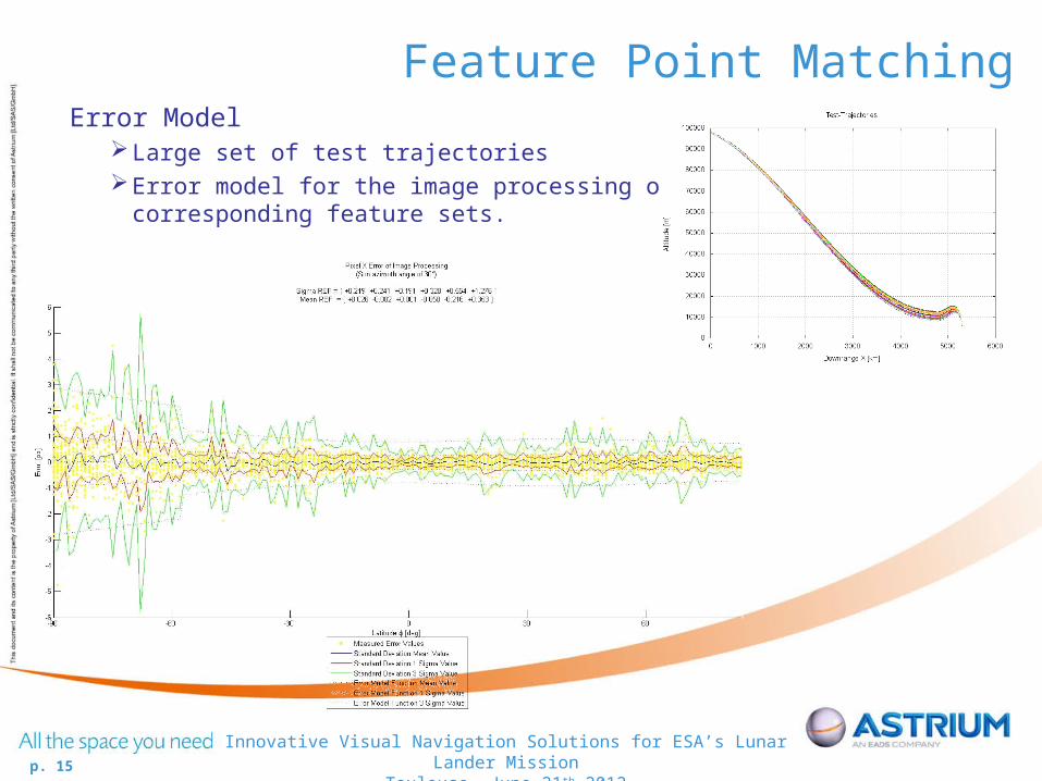
Tests have been performed on virtual image sequences for full coasting arcsVirtual images have been computed from Kaguya and LRO DEMsA total number of 57 trajectories has been analyzed with different start conditionsAn error model has been derived from statistical analysis of these results
p. 15
Innovative Visual Navigation Solutions for ESA’s Lunar Lander MissionToulouse, June 21th 2012
Feature Point MatchingError Model
Large set of test trajectoriesError model for the image processing of
corresponding feature sets.
p. 16
Innovative Visual Navigation Solutions for ESA’s Lunar Lander MissionToulouse, June 21th 2012
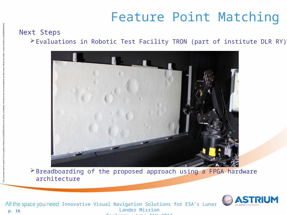
Feature Point MatchingNext Steps
Evaluations in Robotic Test Facility TRON (part of institute DLR RY)
Breadboarding of the proposed approach using a FPGA hardware architecture
p. 17
Innovative Visual Navigation Solutions for ESA’s Lunar Lander MissionToulouse, June 21th 2012
Feature Point TrackingIntroduction:
As the spacecraft moves towards the ground, map errors become significant and feature point matching is no longer reasonable. It is required to apply a visual navigation approach which does not depend on the terrain.
Approach:• Use successively acquired images to match feature points between these two images.
• Displacement of feature points (Optical Flow) gives a conclusion of the s/c translational and rotational motion and of the terrain.
• Apply evaluation of optical flow in order to extract information about s/c motion translation direction.
• Translation direction is used to feed the navigation filter.
Challenge• Terrain ambiguity.
Main Idea to achieve Terrain independency:• Remove rotational influence from optical flow field focus of expansion directly gives the
translation direction, which can be derived from the state vector.
p. 18
Innovative Visual Navigation Solutions for ESA’s Lunar Lander MissionToulouse, June 21th 2012
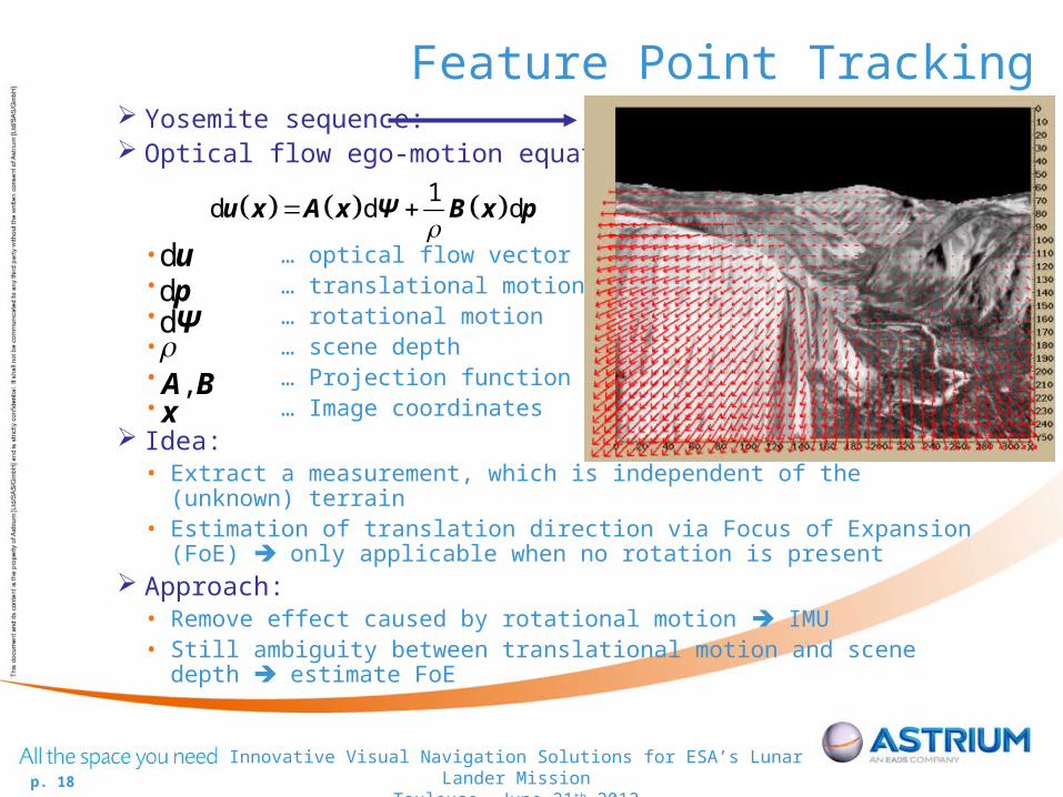
Feature Point Tracking Yosemite sequence: Optical flow ego-motion equation:
• … optical flow vector field• … translational motion• … rotational motion• … scene depth• … Projection function• … Image coordinates
Idea:• Extract a measurement, which is independent of the (unknown) terrain• Estimation of translation direction via Focus of Expansion (FoE) only
applicable when no rotation is present Approach:
• Remove effect caused by rotational motion IMU• Still ambiguity between translational motion and scene depth estimate
FoE
1d d d
u x A x Ψ B x p
du
dΨdp
, A Bx

p. 19
Innovative Visual Navigation Solutions for ESA’s Lunar Lander MissionToulouse, June 21th 2012
Feature Point Tracking Computation of translation direction
• All optical flow vectors intersect in one point Focus of Expansion• Applying a least squares optimisation to estimate the intersection point
Result: Translation Directionvecotor w.r.t. the camera frame
Input to the navigation filter depending on particularmotion, it helps to let the filterconverge
Focus of Expansion
p. 20
Innovative Visual Navigation Solutions for ESA’s Lunar Lander MissionToulouse, June 21th 2012
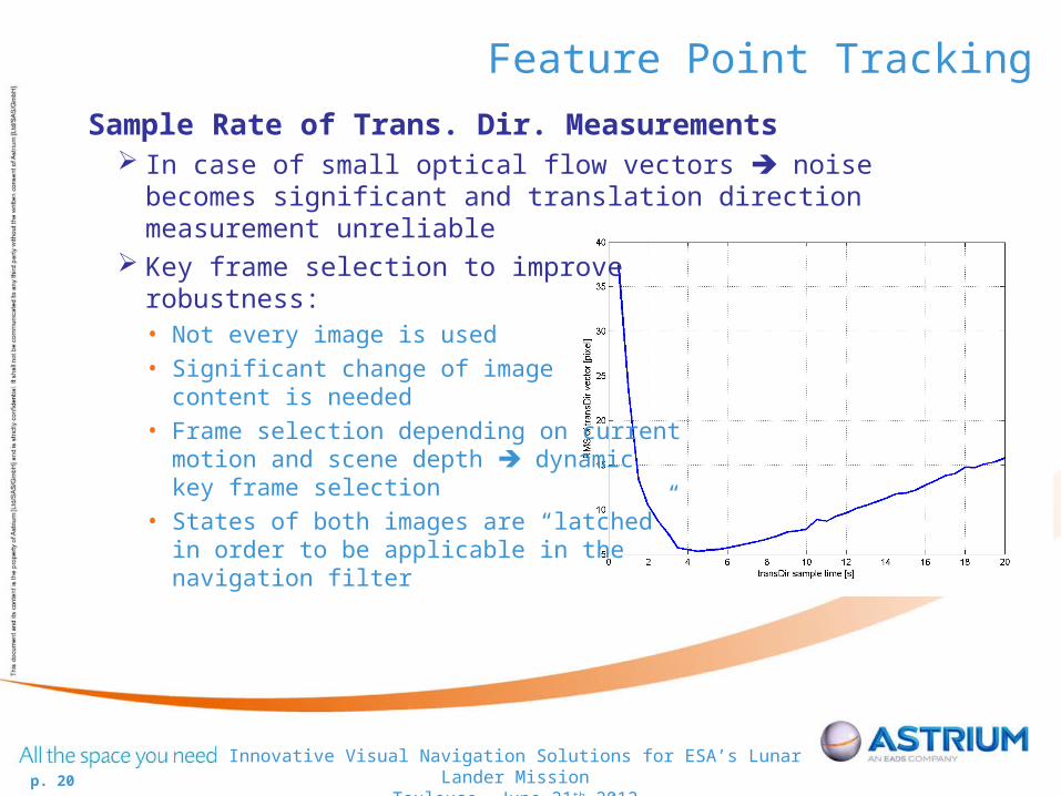
Feature Point Tracking
Sample Rate of Trans. Dir. Measurements In case of small optical flow vectors noise becomes significant and
translation direction measurement unreliable Key frame selection to improve
robustness:• Not every image is used• Significant change of image
content is needed• Frame selection depending on current
motion and scene depth dynamic key frame selection
• States of both images are “latched”in order to be applicable in the navigation filter
p. 21
Innovative Visual Navigation Solutions for ESA’s Lunar Lander MissionToulouse, June 21th 2012
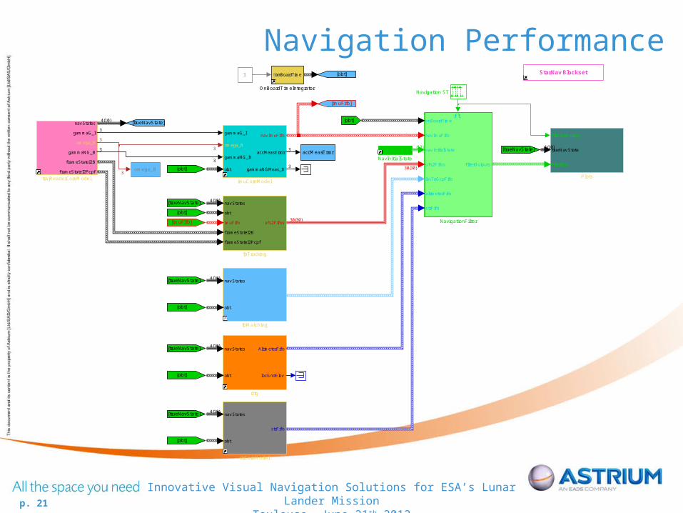
Navigation Performance
nav States
gammaG_I
omega_B
gammaNG_B
f rameStateI2B
f rameStateI2Pcpf
trajReaderCoreModel
nav States
obt
strFif o
strCoreModel
gammaG_I
omega_B
gammaNG_B
obt
nav ImuFif o
accMeasError
gammaNGMeas_B
imuCoreModel
nav States
obt
imuFif o
f rameStateI2B
f rameStateI2Pcpf
uf s2Fif os
fpTracking
nav States
obt
losGcpFif o
fpMatching
nav States
obt
AltimeterFif o
locGndElev
dtg
accMeasError
omega_B
StarNav Blockset
f ilterSampling
trueNav State
f ilterBus
Plots
tDotonBoardTime
OnBoardTimeIntegrator
onBoardTime
nav ImuFif o
nav InitialState
uf s2Fif os
losToGcpFif o
altimeterFif o
strFif o
f ilterOutputs
NavigationFilter
Navigation ST
Nav StateInit
NavInitialState
[imuFifo]
[trueNavState]
[obt]
[trueNavState]
[obt]
[trueNavState]
[obt]
[obt]
[trueNavState]
[imuFifo]
[trueNavState]
[obt]
[trueNavState]
[obt]
[obt]
1
4{10}
3
3
3
3
3
3
4{10}
4{10}
3
4{10}
30{30}
30{30}
{13}
4{10}
3
4{10}
p. 22
Innovative Visual Navigation Solutions for ESA’s Lunar Lander MissionToulouse, June 21th 2012
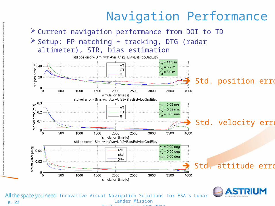
Navigation Performance
Std. position error
Std. velocity error
Std. attitude error
Current navigation performance from DOI to TD Setup: FP matching + tracking, DTG (radar altimeter), STR, bias
estimation
p. 23
Innovative Visual Navigation Solutions for ESA’s Lunar Lander MissionToulouse, June 21th 2012
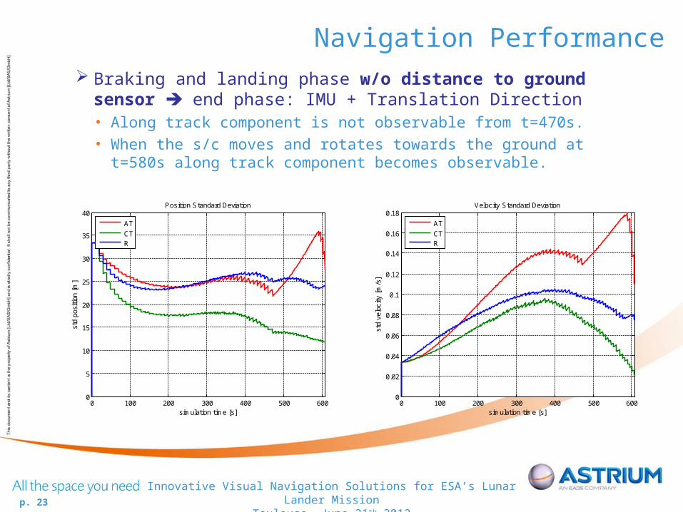
Navigation Performance Braking and landing phase w/o distance to ground sensor end
phase: IMU + Translation Direction• Along track component is not observable from t=470s.• When the s/c moves and rotates towards the ground at t=580s along track
component becomes observable.
0 100 200 300 400 500 6000
5
10
15
20
25
30
35
40
simulation time [s]
std
posi
tion
[m]
Position Standard Deviation
AT
CTR
0 100 200 300 400 500 6000
0.02
0.04
0.06
0.08
0.1
0.12
0.14
0.16
0.18
simulation time [s]
std
velo
city
[m
/s]
Velocity Standard Deviation
AT
CTR

p. 24
Innovative Visual Navigation Solutions for ESA’s Lunar Lander MissionToulouse, June 21th 2012
Summary Overview of ESA’s Lunar Lander Mission Navigation solution proposed by Astrium (Bremen, Toulouse,
Friedrichshafen) Key technologies:
• Feature Point Matching during descent orbit and partly braking phase• Feature Point Tracking during braking and landing phase
Open loop performance stringent requirements are met
p. 25
Innovative Visual Navigation Solutions for ESA’s Lunar Lander MissionToulouse, June 21th 2012
Thank you for yourAttention