Embed Size (px)
Citation preview

Innovative Wideband Techniques in Antennas –
A New OWA Concept
Prof. Jim Breakall, WA3FET Penn State University
Antenna Forum, Dayton Hamvention
May, 2016

In Memoriam: Two Good Friends and Antenna People – Rich Strand, KL7RA, and
John Brosnahan, W0UN, both SK – R.I.P.

Getting Advice for This Talk !!!

1000 Foot Arecibo Dish “HF” Antenna

New Ionospheric Heating Facility at Arecibo Observatory, Puerto Rico

Six Arecibo 100 kW HF Transmitters Future Contest Setup for WP3R for 160 to
10 meters??!!

Typical Dipole Antenna What’s wrong here??!!

Correct Implementation Should Have a Good Current Balun

Inverted-V Dipole

SWR for 80m Dipole – 123.8 ft (RED), 130.6 ft (Blue) and Inverted-V – 124.58 ft (PURPLE), 131.5 ft (BLACK) Both up 50 ft Using #14 Bare Wire from NEC4 Modeling over Average Ground
(epsr=15, sig=.005 S/m)

History of Broadband Antennas – ARRL Antenna Manual,
Chapter 9, Frank Witt, AI1H Cage Dipole - 122 ft 6 in, spreader diameter of 6 in

The Double Bazooka, sometimes called the Coaxial Dipole (RG-58A)

The Crossed Double Bazooka (RG-58A)

Efficient broadband matching with a lumped element LC network

The 80-meter DXer’s Delight

An optimized antenna system with a 3/4 λ Transmission Line Resonator TLR (RG-213)

80-Meter MHz DX Special

Series Transmission-Line Resonator Matching Sections

Broadbanding with the TLR transformer


W8JK – Antennas Book -1950

Prof. Kraus Sent Me His 2nd Edition

Ronald Wyeth Percival King, 1905-2006
Ham Radio Contesting !!!

K3CR Contest Station at Penn State

K3CR Contest Station at Penn State

Antenna Optimization
• Adding an optimizer to an antenna modeling program allows the computer to design the antenna with the designer’s goals in mind.
• NECOPT – Developed at Penn State and very general to optimize just about anything on an antenna and the kitchen sink too.

ANTENNA OPTIMIZERS
• YO – Yagi Optimizer from Brian Beezley, K6STI.
• AO – Antenna Optimizer also from K6STI.
• Both of these based on MiniNec which isn’t as accurate and flexible as NECOPT.
• Other optimizers out there too but none seem to be as powerful as NECOPT.

OPTIMIZED WIDEBAND ANTENNA (OWA)
• Antennas (Dipoles, Yagi’s, etc.) that are optimized to give much wider bandwidth for SWR, Gain, and F/B compared to conventional designs.
• 80M and 40M Dipoles up 35 and 50 ft. to cover whole band with very low SWR.
• Have been used to design 4 element 40M Yagi’s at top contest stations (K3LR, W3LPL, KC1XX, K4JA, K9NS, NO8D, etc.).
• OWA’s for 20, 15, and 10M also designed and used at many top contesters around world and came about from designs at K3CR Rock Springs Antenna Farm.

80M OWA DIPOLE AT 50 FT.

80M OWA DIPOLE AT 50 FT.

80M OWA DIPOLE

80M OWA Dipole Dimensions
• L1 = 66.89 ft
• L2 = 57.68 ft
• L3 = 40.84 ft (Velocity Factor = .66)
• S = 2 ft
• Wire Gauge = #10 Alumoweld
• Height = 50 ft
80M OWA at 50 FT. SWR

MEASURING 80M OWA DIPOLE

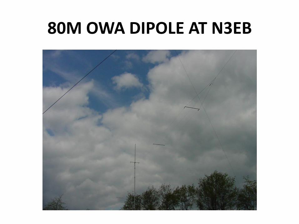
80M OWA DIPOLE BUILT AND TESTED AT N3EB
80 Meter OWA Dipole
1
1.2
1.4
1.6
1.8
2
3.5 3.6 3.7 3.8 3.9 4
Frequency (MHz)
VS
WR GNEC
Daiwa
IFR

80M OWA DIPOLE AT N3EB
80M OWA DIPOLE AT N3EB

80M OWA DIPOLE AT N3EB

80M OWA DIPOLE AT N3EB

80M OWA DIPOLE AT N3EB

80M OWA DIPOLE AT N3EB

80M OWA DIPOLE AT N3EB

160M DIPOLE AT N3EB

40M OWA DIPOLE

40M OWA Dipole Dimensions
• L1 = 35.36 ft
• L2 = 31.43 ft
• L3 = 22.70 ft (Velocity Factor = .66)
• S = 3 inches
• Wire Gauge = #14 Bare
• Height = 35 ft

40M OWA at 35 FT. SWR

40M OWA Dipole Dimensions
• L1 = 35.92 ft
• L2 = 31.55 ft
• L3 = 22.70 ft (Velocity Factor = .66)
• S = 3 inches
• Wire Gauge = #14 Bare
• Height = 50 ft

40M OWA at 50 FT. SWR

40M OWA at 50 FT. SWR

40M OWA at 50 FT. SWR Over 1 MHz of Bandwidth – 15%

Global Optimization of Wideband Impedance Matching Network using only Inductors and
Capacitors – M.S. Thesis, K. Li, Penn State, 2013

Possible Matching Networks

Global Optimization of Best Circuit Configuration for Minimizing Peak SWR for 80m
Dipole 100 ft Above Ground

K3CR Contest Station Inverted-V Dipole at 100 ft

1
1.2
1.4
1.6
1.8
2
2.2
2.4
2.6
2.8
3
3.45 3.5 3.55 3.6 3.65 3.7 3.75 3.8 3.85 3.9
VSWR
Frequency (MHz)
K3CR 80m Inverted-V 100 ft (No Matching)
FEKO
RigExpert

Agilent Advanced Design System (ADS) Optimization of Measured K3CR Inverted-V Dipole
C1 = 3724 pf C2 = 7667 pf L1 = .719 uH

SWR After Matching Circuit Optimization from 3.5 to 3.85 MHz

Circuit Analysis at 3.7 MHz for 1600 watts of power. Currents are around 30 amps peak.

Another Method of Impedance Matching Using Series-Section Transmission Line Transformers

Series Transmission Line Optimization over Frequency – Minimize Peak SWR


K3CR 80M Inverted-V 100 ft Optimized Series Transmission Line Matching Dimensions
• Two 50 Ohm RG-213 lines (VF = .66) in Parallel each 89 ft long
• One 75 Ohm RG-11 line (VF = .66) = 29.5 ft long
• Balun Designs Model 1116d

1
1.2
1.4
1.6
1.8
2
2.2
2.4
2.6
2.8
3
3.45 3.5 3.55 3.6 3.65 3.7 3.75 3.8 3.85 3.9
VSWR
Frequency (MHz)
K3CR 80m Inverted-V 100 ft (Series Transmission Line Matching)
RigExpert
ADS
Feko

40m Inverted-V at 40 ft Optimized Series Transmission Line Matching Dimensions
• Each half-length leg is 32’ 11” long
• Two 35 Ohm RG-83 lines (VF = .66) in Parallel each 44’ 10.5” long
• One 75 Ohm RG-11 line (VF = .66) = 7’ 5.25” long


1
1.2
1.4
1.6
1.8
2
2.2
2.4
2.6
2.8
3
7 7.05 7.1 7.15 7.2 7.25 7.3
VSWR
Frequency (MHz)
Optimized 40m Inverted-V at 40 ft at N3EB
NEC4
Anritsu

Optimized 40m Inverted-V at 40 ft at N3EB

Optimized 40m Inverted-V at 40 ft at N3EB

Measuring the SWR with the Anritsu S33IL Analyzer at N3EB

40m Inverted-V Different Line Matching Impedance
Two 35 ohm lines (17.5 ohms) (RED), Two 50 ohm lines (25 ohms) (BLUE), Four 50 ohm lines (12.5 ohms) (Purple)
Parallel 35 ohm lines – 44.89 ft, 75 ohm line – 7.43 ft, dipole half-length = 32.90 ft Parallel 50 ohm lines – 45.13 ft, 75 ohm line – 7.36 ft, dipole half-length = 33.03 ft Four 50 ohm lines – 44.87 ft, 75 ohm line – 6.51 ft, dipole half-length = 32.80 ft

Optimized 40m Flat Dipole at 40 ft using Two Parallel 35 Ohm Lines and One 75 Ohm Line

Can This Technique Work with Yagis? 4 Element OWA Yagi 48 ft Boom at 165 ft

Measured and FEKO Simulated SWR for 4 Element 40m OWA Yagi at 165 ft
1
1.2
1.4
1.6
1.8
2
2.2
2.4
2.6
2.8
3
6.6 6.7 6.8 6.9 7 7.1 7.2 7.3 7.4 7.5 7.6 7.7
SWR
Frequency (MHz)
4 Element OWA 40m Yagi
Meas
FEKO Cable

4 Element 40m OWA Yagi on 48 ft Boom at 165 ft – Frequencies from 7.0 to 7.3 MHz

Optimize a 3 Element 40m Yagi on the Same 48 ft Boom at 165 ft

3 Element 40m Yagi on 48 ft Boom up 165 ft – Frequencies from 7.0 to 7.3 MHz

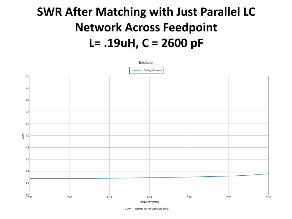
SWR After Matching with Just Parallel LC Network Across Feedpoint
L= .19uH, C = 2600 pF
SWR After Matching with Just Parallel LC Network Across Feedpoint
L= .19uH, C = 2600 pF

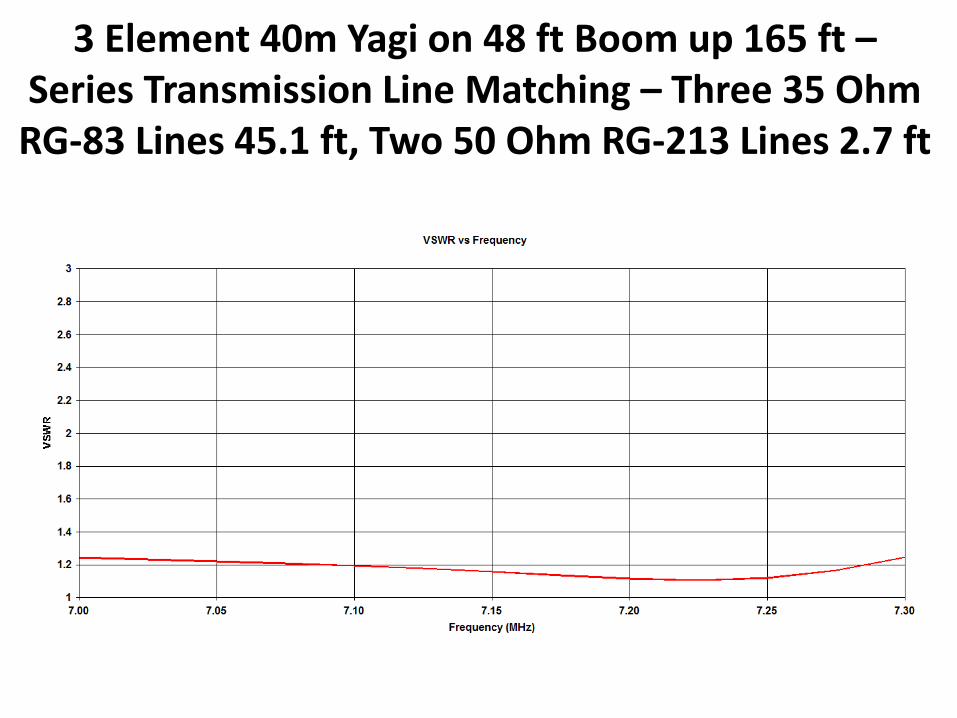
3 Element 40m Yagi on 48 ft Boom up 165 ft – Series Transmission Line Matching – Three 35 Ohm RG-83
Lines 45.1 ft, Two 50 Ohm RG-213 Lines 2.7 ft
3 Element 40m Yagi on 48 ft Boom up 165 ft – Series Transmission Line Matching – Three 35 Ohm
RG-83 Lines 45.1 ft, Two 50 Ohm RG-213 Lines 2.7 ft