Embed Size (px)
Citation preview

- 1 - Dissemination level: Confidential
This project has been carried out under a contract awarded by the European Commission. No part of this report may be used, reproduced and/or disclosed in any form or by any means without the prior written permission of the INOUI project partners. © 2007 – All rights reserved
Contract no.: TREN/07/FP6AE/S07.69061/037191
INOUI INNOVATIVE OPERATIONAL UAS INTEGRATION
Instrument: STREP (Specific Targeted Research Project)
Thematic Priority: AERO-2005-4.g Open Upstream Research
D2.2 ASSESSMENT OF TECHNOLOGY FOR UAS INTEGRATION
Due date of deliverable: 22/04/2009 Actual submission date: 25/05/2009
Start date of project: 09/10/2007 Duration: 24 months
Organisation name of lead for this deliverable: ISDEFE
Revision: Version 1.00
Approval status
Author Verification Authority Project Approval
ISDEFE ISDEFE DFS
Jorge Bueno Marga Martín Achim Baumann
Systems Engineer/WP2 Leader ISDEFE INOUI Quality Manager INOUI Project Coordinator
21/05/2009 21/05/2009 25/05/2009
Project co-funded by the European Commission within the Sixth Framework Programme (2002-2006)
Dissemination Level PU Public X
PP Restricted to other programme participants (including the Commission Services)
RE Restricted to a group specified by the consortium (including the Commission Services)
CO Confidential, only for members of the consortium (including the Commission Services)
Title: D2.2 Assessment of Technology for UAS Integration
Date: 25/05/2009 Document ID: INOUI-WP2.2-ISD-D2.2-PU-v1.00.doc
Innovative Operational UAS
Integration Revision: Version 1.0
- 2 - Dissemination level: Confidential
This project has been carried out under a contract awarded by the European Commission. No part of this report may be used, reproduced and/or disclosed in any form or by any means without the prior written permission of the INOUI project partners. © 2007 – All rights reserved
Contributing Partner Company Name ISDEFE Juan Mendi, Jorge Bueno DFS Stefan Tenoort BR&TE David Esteban ONERA Claude Le Tallec, Antoine Joulia RDE Klaus Wohlers
Distribution List
Company Name Company Name European Commission Gilles Fartek
Hoang VU DUC ONERA Claude Le Tallec
Antoine Joulia DFS Achim Baumann
Marita Lintener Stefan Tenoort
RDE Klaus Wohlers Reimund Küke
ISDEFE Juan Alberto Herrería Cristina Martinez Carlos Planter Juan Mendi Jorge Bueno
INNAXIS Paula López-Catalá
BRTE David Esteban Carlos Montes
OFFIS Sönke Eilers Dr. Matthias Brucke
Document Change Log
Rev. Edition date Author Modified Sections/Pages
Comments
0.1 01-07-2008 ISD/ J. Bueno All Creation of the document 0.2 30-10-2008 ISD/ J. Bueno
J. Mendi All Contribution from ISDEFE
0.3 22-01-2009 RDE/ K. Wohlers Section 2.2 Contribution from RDE 0.4 27-02-2009 BRT/ D. Esteban Sections 2.3, 3.3,
4.3, 5.3 Contribution from BRTE
0.5 27-03-2009 DFS/ S. Tenoort Sections 3.1, 5.1 Contribution from DFS V0.6 27-03-2009 ISD/ J. Bueno All Format of the document for
internal review V0.61 03-04-2009 ISD/J. Bueno All Integration of comments from
DFS V0.7 20-04-2009 ISD/J. Bueno All Integration of comments from all
partners and issue of the final version to be reviewed by PMB/PCO
V1.00 21-05-2009 ISD/J. Bueno All Integration of comments from PCO and issue of the final version to EC

Title: D2.2 Assessment of Technology for UAS Integration
Date: 25/05/2009 Document ID: INOUI-WP2.2-ISD-D2.2-PU-v1.00.doc
Innovative Operational UAS
Integration Revision: Version 1.0
- 3 - Dissemination level: Confidential
This project has been carried out under a contract awarded by the European Commission. No part of this report may be used, reproduced and/or disclosed in any form or by any means without the prior written permission of the INOUI project partners. © 2007 – All rights reserved
Table of Contents
1 Introduction ............................................................................................................................7
1.1 Background......................................................................................................................7 1.2 Purpose of the Document ................................................................................................7 1.3 Document Structure .........................................................................................................8 1.4 Applicable and Reference Documents .............................................................................8 1.5 Glossary ........................................................................................................................11
2 UAS Technology Needs.......................................................................................................14
2.1 Introduction ....................................................................................................................14 2.2 General..........................................................................................................................14 2.3 Surveillance/Observation and Cargo Flight Applications Particularities ..........................30 2.4 Station Keeping Applications..........................................................................................34
3 ATM Technology Needs.......................................................................................................35
3.1 General..........................................................................................................................35 3.2 Surveillance/Observation Applications ...........................................................................37
3.2.1 Communications ........................................................................................................38 3.2.2 Navigation..................................................................................................................39 3.2.3 Surveillance ...............................................................................................................40 3.2.4 Other..........................................................................................................................45
3.3 Cargo Flight Applications ...............................................................................................46 3.4 Station Keeping Applications..........................................................................................46
4 UAS Technology Gaps.........................................................................................................47
4.1 Introduction ....................................................................................................................47 4.2 General..........................................................................................................................47 4.3 Surveillance/Observation and Cargo Flight Applications Particularities ..........................55
5 ATM Technology Gaps.........................................................................................................58

Title: D2.2 Assessment of Technology for UAS Integration
Date: 25/05/2009 Document ID: INOUI-WP2.2-ISD-D2.2-PU-v1.00.doc
Innovative Operational UAS
Integration Revision: Version 1.0
- 4 - Dissemination level: Confidential
This project has been carried out under a contract awarded by the European Commission. No part of this report may be used, reproduced and/or disclosed in any form or by any means without the prior written permission of the INOUI project partners. © 2007 – All rights reserved
5.1 General ..........................................................................................................................58 5.2 Surveillance/Observation Applications ...........................................................................58
5.2.1 Communications ........................................................................................................59 5.2.2 Navigation ..................................................................................................................60 5.2.3 Surveillance ...............................................................................................................63 5.2.4 Other..........................................................................................................................78
5.3 Cargo Flight Applications ...............................................................................................81 5.4 Station Keeping Applications..........................................................................................81
6 Summary and Conclusions .................................................................................................82

Title: D2.2 Assessment of Technology for UAS Integration
Date: 25/05/2009 Document ID: INOUI-WP2.2-ISD-D2.2-PU-v1.00.doc
Innovative Operational UAS
Integration Revision: Version 1.0
- 5 - Dissemination level: Confidential
This project has been carried out under a contract awarded by the European Commission. No part of this report may be used, reproduced and/or disclosed in any form or by any means without the prior written permission of the INOUI project partners. © 2007 – All rights reserved
List of Figures
Figure 3-1 Radio Altimeter (Source: SOFIA Project) ................................................................45 Figure 5-1 SWIM Layered Architecture (Source: ATLANTIDA Project) ....................................59 Figure 5-2 Agreed approach for implementation of Datalink Technologies (Source:
EUROCONTROL) ..................................................................................................64 Figure 5-3 Principle of TIS-B Operation (Source: SOFIA Project) ............................................66 Figure 5-4 TIS-B Concept (Source: SOFIA Project) .................................................................67 Figure 5-5 TCAS levels of protection (Source: SOFIA Project) ................................................70 Figure 5-6 TAWS Look-Ahead Capability (Source: SOFIA Project) .........................................75

Title: D2.2 Assessment of Technology for UAS Integration
Date: 25/05/2009 Document ID: INOUI-WP2.2-ISD-D2.2-PU-v1.00.doc
Innovative Operational UAS
Integration Revision: Version 1.0
- 6 - Dissemination level: Confidential
This project has been carried out under a contract awarded by the European Commission. No part of this report may be used, reproduced and/or disclosed in any form or by any means without the prior written permission of the INOUI project partners. © 2007 – All rights reserved
List of Tables
Table 2-1 UAS Technology Need Description for Requirements Identified – General.............15 Table 2-2 UAS Technology Need Description for Requirements Identified –
Surveillance/Observation and Cargo Flight Applications.........................................31 Table 4-1 UAS Technology Gaps - General............................................................................47 Table 4-2 UAS Technology Gaps – Surveillance/Observation and Cargo Flight
Applications ............................................................................................................55 Table 5-1 Geometric altitude relation to colours of the Terrain Awareness Display in
TAWS.....................................................................................................................77

Title: D2.2 Assessment of Technology for UAS Integration
Date: 25/05/2009 Document ID: INOUI-WP2.2-ISD-D2.2-PU-v1.00.doc
Innovative Operational UAS
Integration Revision: Version 1.0
- 7 - Dissemination level: Confidential
This project has been carried out under a contract awarded by the European Commission. No part of this report may be used, reproduced and/or disclosed in any form or by any means without the prior written permission of the INOUI project partners. © 2007 – All rights reserved
1 Introduction
The main objective of the INOUI project is to success the challenge of integrating UAS in the 2020 airspace environment. By taking into account the context of the ever changing ATM environment, the goal is to develop a roadmap how to integrate UAS into the operational concept and architecture for the mentioned temporal framework. Development of the INOUI project runs in parallel with SESAR (Single European Sky ATM Research) and aims complementing its development phase, filling the possible existing gaps in regard to the particularities of UAS.
1.1 Background
INOUI (Innovative Operational UAV Integration) project is a response to the Research Domain 4.g « Innovative Air Traffic Management Research » of the FP6-2005-AERO-4, Research Area « Open Upstream Research ».
The main objective of INOUI is to develop a roadmap how to integrate UAS into the operational concept and architecture for the future by assessing different domains of the ATM system. The idea of integrating UAS into the 2020 airspace environment came up from the following two facts:
• The increasing demand of UAS operations coming from different sources • The fact that actually UAS fly only at a very low altitude or in segregated airspace
(regarding to the military nature of the operations)
It is forecast that air traffic will increase three times its actual figures and that is without considering UAS. In order to ensure that the future Air Traffic Management (ATM) is able to face this challenge, SESAR was founded which is defining the future European Air Traffic Management (ATM) System for 2020 and beyond. Main goals of SESAR are to increase actual ATM capacity, to improve the safety performance, to reduce the effects on the environment produced by the flights and to reduce ATM service costs to the airspace users.
Now, bearing in mind that UAS traffic comes on top of the above forecast to the future air traffic, additional considerations shall be taken into account. INOUI aims complementing SESAR by facilitating the integration of the UAS in the foreseen airspace and airport environment. To it, INOUI defines an operational concept, propose operational procedures and assess the technologies to support them, trying to fill in the gaps of the SESAR definition phase with regard to the particularities of UAS.
1.2 Purpose of the Document
The purpose of this document is to match the ground and airborne technologies addressed in WP2.1 to the operational concept resulting from WP1 in order to give potential technological

Title: D2.2 Assessment of Technology for UAS Integration
Date: 25/05/2009 Document ID: INOUI-WP2.2-ISD-D2.2-PU-v1.00.doc
Innovative Operational UAS
Integration Revision: Version 1.0
- 8 - Dissemination level: Confidential
This project has been carried out under a contract awarded by the European Commission. No part of this report may be used, reproduced and/or disclosed in any form or by any means without the prior written permission of the INOUI project partners. © 2007 – All rights reserved
solutions allowing UAS to fly into the civil airspace, and to determine the gaps and weaknesses of such technology to cope with the operational concept needs.
Each technology previously identified has been traced to the operational needs derived from WP1. The feasibility of the technology to cope with the operational requirements has also been assessed. Thus the gaps in technological developments for both ground and airborne systems have been identified with respects to the operational requirements in the 2020 timeframe.
1.3 Document Structure
Section 1 – Introduction
Section 2 – UAS Technology Needs
Section 3 – ATM Technology Needs
Section 4 – UAS Technology Gaps
Section 5 – ATM Technology Gaps
Section 6 – Conclusions
1.4 Applicable and Reference Documents
INOUI (2007): Annex I - Description of work.
INOUI D1.1 Definition of the Environment for Civil UAS Applications. INOUI consortium. 15-02-2008. INOUI-WP1.1-D1.1-DFS-PU-v1.0.
INOUI D1.2 Concept for Civil UAS Applications. INOUI Consortium. 30-08-2008. INOUI-WP1.2-DFS-D1.2-DFS-PU-v1.0.
INOUI D1.3 Proposal for the Integration of UAS into the Civil Airspace. INOUI Consortium. 22-03-2009. INOUI-WP1.3-D1.3-DFS-PU-v1.0.
INOUI D2.1 Report on Technology Systems Solutions. INOUI Consortium. 10-09-2008. INOUI-WP2.1-DFS-D2.1-PU-v1.0.
INOUI D4.1 UAS within the 2020 ATM SWIM-Enabled System. INOUI Consortium. 17-12-2008. INOUI-WP4.1-BRT-D4.1-PU-v1.0.

Title: D2.2 Assessment of Technology for UAS Integration
Date: 25/05/2009 Document ID: INOUI-WP2.2-ISD-D2.2-PU-v1.00.doc
Innovative Operational UAS
Integration Revision: Version 1.0
- 9 - Dissemination level: Confidential
This project has been carried out under a contract awarded by the European Commission. No part of this report may be used, reproduced and/or disclosed in any form or by any means without the prior written permission of the INOUI project partners. © 2007 – All rights reserved
INOUI D4.2 New UAS-related COP Actors. INOUI Consortium. 15-01-2009. INOUI-WP4.2-BRT-D-New UAS-related COP actors-CO-v1.1
CAA Civil Aviation Authority, UK (2008): CAP722 - Unmanned Aircraft System Operations in UK Airspace – Guidance (3rd edition). ISBN 978 0 11792 020 0.
EUROCONTROL (2007), Eurocontrol Specifications for the Use of Military Unmanned Aerial Vehicles as Operational Air Traffic outside Segregated Airspace, Brussels – EUROCONTROL-SPEC-0102.
ICAO Annex 10 (2007): Aeronautical Telecommunications, Volume III – Communication Systems (2nd edition).
ICAO Annex 10 (2007): Aeronautical Telecommunications, Volume IV – Surveillance and Collision Avoidance Systems (4th edition).
ICAO Annex 2 (2005): Rules of the Air (10th edition).
SESAR Consortium (2007a): D3 The ATM Target Concept. DLM-0612-001-02-00a.
SESAR Consortium (2007b): SESAR Definition Phase: Baseline Operational Description for the Mid-term Task 2.2.4 – Milestone 3. DLT-0612-224-00-07.
SESAR Consortium (2007c): SESAR Definition Phase: Concept of Operations. Task 2.2.2 – Milestone 3. DLT-0612-222-02-00.
SESAR Consortium (2007d): SESAR Definition Phase: Technology Assessment. Task 2.5.x - Milestone 3. DLT-0612-25x-00-05.
USICO (2003): Concept of UAV integration in ATC/ ATM Environments.
Darren Smith. Programme SWIM-SUIT. Information Content and Service Requirements. Doc. No.: E366-01-05678-USR.
SOFIA D1.1 Definition of the FRF Environment. Selex Galileo + SOFIA Consortium. 25-04-2007. SOFIA-WP1.1-GAL-D1.1-DEN-CO.v2.0.
SOFIA D1.2 Definition of the FRF procedures. DFS + SOFIA Consortium. 04-12-2007. SOFIA-WP1.2-DFS-D1.2-DPR-RE-v2.0.
SOFIA D2.1 FRF Functions Allocation. Alenia SIA + SOFIA Consortium. 10-07-2007. SOFIA-WP2.1-SIA-D2.1-FFA-RE-v1.0.
SOFIA D2.2.1 FRF Preliminary Safety Assessment (aircraft and airspace levels). ISDEFE + SOFIA Consortium. 11-10-2007. SOFIA-WP2.2-ISD-D2.2.1-PSSA_1-RE-v1.0.

Title: D2.2 Assessment of Technology for UAS Integration
Date: 25/05/2009 Document ID: INOUI-WP2.2-ISD-D2.2-PU-v1.00.doc
Innovative Operational UAS
Integration Revision: Version 1.0
- 10 - Dissemination level: Confidential
This project has been carried out under a contract awarded by the European Commission. No part of this report may be used, reproduced and/or disclosed in any form or by any means without the prior written permission of the INOUI project partners. © 2007 – All rights reserved
SOFIA D2.2.2 FRF Final Safety Assessment (aircraft and airspace levels). ISDEFE + SOFIA Consortium. 30-05-2008. SOFIA-WP2.2-ISD-D2.2.2-PSSA-CO-v1.0.
iFly D1.1 A3 High Level ConOps. ISDEFE + iFly Consortium. 18 January 2008.
ADS-B for Dummies – 1090 MHz Extended Squitter presentation. Eurocontrol. CASCADE Project.
Cockpit Display of Traffic Information – What is compatible with Australia’s ADS-B program?. April 2005. Technology Development Airservices Australia.
Automatic Dependent Surveillance - Broadcast / Cockpit Display of Traffic Information: Innovations in Pilot-Managed Departures. O. Veronika Prinzo Civil Aerospace Medical Institute Federal Aviation Administration. April 2002. Cockpit Display of Traffic Information: The effects of Traffic Load, Dimensionality and Vertical Profile. Amy L. Alexander and Christopher D. Wickens University of Illinois, Aviation Research Lab Savoy, Illinois. Proceedings of the 45th Annual Meeting of the Human Factors and Ergonomics Society. Santa Monica, CA: Human Factors & Ergonomics Society. 2001. DEVELOPMENT OF COCKPIT DISPLAY OF TRAFFIC INFORMATION (CDTI). ICAO. The Third Meeting of Automatic Dependent Surveillance – Broadcast (ADS-B) Study and Implementation Task Force (ADS-B TF/3). Bangkok, 23-25 March 2005. RTCA Special Committee 186, Working Group 3. ADS-B 1090 MOPS, Revision A. Meeting #10. Proposed Appendix M (draft version 5) to the 1090 MHz ADS-B MOPS to define Extended Range Reception Techniques. Prepared by Ron Jones, FAA, ASD-140. 1090-WP-10-11. 26 March 2002. Brake Control Systems for Unmanned Air Vehicles August, 2001. CRANE CO. Hydro-Aire Inc. Technical Document Series. Stuart E. Johnson. Action Plan 17 Future Communications Study. Final Conclusions and Recommendations Report Version II, november 2007. EUROCONTROL /FAA. Memorandum of Cooperation

Title: D2.2 Assessment of Technology for UAS Integration
Date: 25/05/2009 Document ID: INOUI-WP2.2-ISD-D2.2-PU-v1.00.doc
Innovative Operational UAS
Integration Revision: Version 1.0
- 11 - Dissemination level: Confidential
This project has been carried out under a contract awarded by the European Commission. No part of this report may be used, reproduced and/or disclosed in any form or by any means without the prior written permission of the INOUI project partners. © 2007 – All rights reserved
1.5 Glossary
Acronym Definition 4D Four Dimensions ACARE Advisory Council for Aeronautics Research in Europe ACARS Aircraft Communication Addressing and Reporting System ACAS Airborne Collision Avoidance System ACC Area Control Centre ACL Anti-Collision Lighting ADF Automatic Direction Finder ADS-B Automatic Dependent Surveillance Broadcast AFTN Aeronautical Fixed Telecommunication Network AMHS Aeronautical Message Handling Service ANSP Air Navigation Service Provider AoA Angle of Attack AOC Airlines Operational Communications ASAS Airborne Separation Assistance (Assurance) Systems AS Airspeed ASI Actuator Sensor Interface A-SMGCS Advanced Surface Movement Guidance and Control System ATC Air Traffic Control ATCO Air Traffic Controller ATIS Automatic Terminal Information Service ATFCM Air Traffic Flow and Capacity Management ATM Air Traffic Management ATN Aeronautical Telecommunications Network BRLOS Beyond Radio Line Of Sight BR&TE Boeing Research and Technology Europe SL C2 Command and Control C3 Command, Control and Communication CASCADE Co-operative ATS through Surveillance and Communication Applications
Deployed in ECAC CDM Collaborative Decision Making CFMU Central Flow Management Unit CNS Communication, Navigation, Surveillance CPDLC Controller Pilot Data Link Communication CS Control Station CTR Control zone DB Data Base DFS DFS Deutsche Flugsicherung GmbH DME Distance Measuring Equipment DoC Rate of Descent DVP Development Plan EC European Commission ECAC European Civil Aviation Conference EFB Electronic flight bags
Title: D2.2 Assessment of Technology for UAS Integration
Date: 25/05/2009 Document ID: INOUI-WP2.2-ISD-D2.2-PU-v1.00.doc
Innovative Operational UAS
Integration Revision: Version 1.0
- 12 - Dissemination level: Confidential
This project has been carried out under a contract awarded by the European Commission. No part of this report may be used, reproduced and/or disclosed in any form or by any means without the prior written permission of the INOUI project partners. © 2007 – All rights reserved
Acronym Definition EGNOS European Geostationary Navigation Overlay System Services ESARR EUROCONTROL Safety Regulatory Requirement EU European Union EUROCAE European Organization for Civil Aviation Electronics EUROCONTROL European Organisation for the Safety of Air Navigation EVS Enhanced Vision System FCS Flight Control System FIR Flight Information Region FMS Flight Management System FP Framework Programme FPL Flight Plan FRF Flight Reconfiguration Function G2G Gate To Gate GAT General Air Traffic GBAS Ground Based Augmentation System GCS Ground Control Station GLONASS GLObal'naya NAvigatsionnaya Sputnikovaya Sistema
(Global Navigation Satellite System) GNSS Global Navigation Satellite System GPS Global Positioning System HUD Head-Up Display ICAO International Civil Aviation Organisation IFATS Innovative Future Air Transport System IFR Instrumental Flight Rules ILS Instrument Landing System INA Innaxis – Fundación Instituto de Investigación ISD Isdefe – Ingeniería de Sistemas para la Defensa de España JPALS Joint Precision Approach and Landing Systems LED Light Emitting Diode MLAT Multi Lateration MLS Microwave Landing System MMR Multi Mode Receiver MSPSR Multi Static Primary Surveillance Radar NDB Non-Directional Beacon OAT Operational Air Traffic ONERA Office National d’Etudes et de Recherches Aéronautiques PCO Project Co-ordinator PBIT Power-up Built-In Test PMP Project Management Plan PSR Primary Surveillance Radar RCS Radar Cross Section RDE Rheinmetall Defence Electronics GmbH RLOS Radio Line Of Sight

Title: D2.2 Assessment of Technology for UAS Integration
Date: 25/05/2009 Document ID: INOUI-WP2.2-ISD-D2.2-PU-v1.00.doc
Innovative Operational UAS
Integration Revision: Version 1.0
- 13 - Dissemination level: Confidential
This project has been carried out under a contract awarded by the European Commission. No part of this report may be used, reproduced and/or disclosed in any form or by any means without the prior written permission of the INOUI project partners. © 2007 – All rights reserved
Acronym Definition RoC Rate of Climb RVSM Reduced Vertical Separation Minima SATCOM Satellite Voice and Data communications SBAS Satellite-Based Augmentation System SES Single European Sky SESAR Single European Sky ATM Research Programme SMGCS Surface Movement Guidance and Control System SSR Secondary Surveillance Radar TCAS Traffic Collision Avoidance System TD taxi-guidance display TIS-B Traffic Information Service - Broadcast TMA Terminal Manoeuvring Area TO Take-off UAC Upper Area Control Center UAS Unmanned Aircraft Systems UAV Unmanned Aerial Vehicles UAV-p UAV pilot UIR Upper Flight Information Region VDL VHF (Very High Frequency) Data-Link VFR Visual Flight Rules VHF Very High Frequency VNAV Vertical NAV VoIP IP voice VOR VHF Omni-directional Radio Range WAAS Wide Area Augmentation System WAM Wide Area Multi-lateration WG Working Group WP Work Package WRC World Radio communication Conference XPDR Transponder

Title: D2.2 Assessment of Technology for UAS Integration
Date: 25/05/2009 Document ID: INOUI-WP2.2-ISD-D2.2-PU-v1.00.doc
Innovative Operational UAS
Integration Revision: Version 1.0
- 14 - Dissemination level: Confidential
This project has been carried out under a contract awarded by the European Commission. No part of this report may be used, reproduced and/or disclosed in any form or by any means without the prior written permission of the INOUI project partners. © 2007 – All rights reserved
2 UAS Technology Needs 2.1 Introduction
As well as manned aviation will benefit from UAS technology development (i.e. Sense & Avoid), UAS will also benefit from existing or future manned aviation technology.
In INOUI “D1.3 Proposal for the Integration of UAS into the Civil Airspace” a first concept that INOUI proposes for the integration of Surveillance/Observation, Station Keeping and Cargo Flight UAS applications is described.
Besides a concept the integration of the mentioned applications needs a set of technologies enabling it. These technologies range from CNS (Communication, Navigation and Surveillance) equipment on-board the UA to ground equipment such as, for instance, navigation aids. These technologies are well known by the civil aviation community. There are, however, new technologies emerging in the field of UAS, especially if it is considered that the pilot is not on-board the UA. This means that new fields for technology development have arisen, which are control station equipment and on-board technology to replace tasks usually assigned to the pilot such as See & Avoid.
Based on the INOUI Operational Concept and in the current and foreseen technologies identified in INOUI “D2.1 Report on Technology Systems Solutions”, a crosscheck between the concept and the technologies is necessary to be performed. In the following the technical requirements derived from the operational concept and a description of the technology needed to fulfil such requirements is shown. The aim of this analysis is to identify what are the technologies available as a potential solution for the integration of UAS and what are the gaps, i.e. what are the fields where further technological research and development is needed.
2.2 General
In the following table the technical and operational requirements for civil UAS applications defined in INOUI “D1.3 Proposal for the Integration of UAS into the Civil Airspace” have been assessed and have translated into a technology need. The technologies described are based on the descriptions of INOUI “D2.1 Report on Technology Systems Solutions”. It has to be noted that these requirements are related to Civil UAS applications performed with a fixed wing UAS carrying out either Surveillance/Observation, Cargo Flight or Station Keeping applications. For those applications carried out with other types of UAS please see under sections 2.3 and 2.4 in this document.

Title: D2.2 Assessment of Technology for UAS Integration
Date: 25/05/2009 Document ID: INOUI-WP2.2-ISD-D2.2-PU-v1.00.doc
Innovative Operational UAS
Integration Revision: Version 1.0
- 15 - Dissemination level: Confidential
This project has been carried out under a contract awarded by the European Commission. No part of this report may be used, reproduced and/or disclosed in any form or by any means without the prior written permission of the INOUI project partners. © 2007 – All rights reserved
Table 2-1 UAS Technology Need Description for Requirements Identified – General
Requirement ID
Requirement Description Technology Need Description
REQ-MAN-GEN-PTO-001
The UA shall have brakes to allow it to stand in its parking position.
Brake systems that allow the UA to stand in its parking position, as well as to control speed, both during taxiing and landing. Could be, among others: brake-by-wire hydraulic or autonomous brake control.
REQ-MAN-GEN-PTO-002
The ground personnel shall have the means to ensure that the UA remains in its parking position until it receives authorization to initiate taxi and to assure that the UA and CS (Control Station) are in condition for safe flight.
Brake systems and chocks.
REQ-MAN-GEN-PTO-003
The UAS shall be capable of communicating with ATCO (Air Traffic Controller) while it is in its parking position either receiving or transmitting information (aircraft identifier, flight duration, ATIS (Air Traffic Information System), meteorology, runway in use, etc.). Communication shall be performed in, at least, the following way:
UA Pilot (on the CS) transmits/receives information directly to/from ATCO via radio communications, transmitting it then to the UA when it is started up.
Radio communication system between pilot and ATCO. With a terrestrial network or relay to the CS.
Automatic information process between ATCO and UA through a data link.
REQ-MAN-GEN-PTO-004
UA Pilot shall be able to select the appropriate frequency upon request of the ATCO.
Automatic or remotely controlled frequency selector on the CS through a terrestrial network or relay from the UA, in response to a information sent by ATCO.
REQ-MAN-GEN-PTO-005
The UAS shall have the means to be started up either from the control station or directly by the ground personnel while the UA is in its parking position.
Computer Key with an user registration application allowing the UA start up
REQ-MAN-GEN-PTO-006
The UA should be capable of being started up by using external power.
Ground Power Units
REQ-MAN-GEN-PTO-007
The CS shall be already started up and working before the UA is started up.
Specific software agent on line can synchronize the UA and CS starting up.

Title: D2.2 Assessment of Technology for UAS Integration
Date: 25/05/2009 Document ID: INOUI-WP2.2-ISD-D2.2-PU-v1.00.doc
Innovative Operational UAS
Integration Revision: Version 1.0
- 16 - Dissemination level: Confidential
This project has been carried out under a contract awarded by the European Commission. No part of this report may be used, reproduced and/or disclosed in any form or by any means without the prior written permission of the INOUI project partners. © 2007 – All rights reserved
Requirement ID
Requirement Description Technology Need Description
REQ-MAN-GEN-PTO-008
After the UA is started up, every system on-board shall perform a PBIT (Power-up Built-In Test) and send the results to the CS to be checked by the UA pilot. The CS equipment should also perform a PBIT to check if there is any malfunction.
Systems monitoring the state of critical systems onboard, during all phases of the flight and even capable to make predictions in a short and medium term regarding potential risks.
REQ-MAN-GEN-PTO-009
The UA pilot shall be able to create the flight plan on board the CS and then transmit it to the UA via data link, as well as all the possible databases allowing it to perform a safe and secure flight.
ACARS (aircraft communication addressing and reporting system) or AOC (airlines operational communications),
REQ-MAN-GEN-PTO-010
The UA Pilot shall be able to contact the ATCO via radio communications to inform that the UA is ready to initiate taxiing and receive from ATCO the taxiing information to reach the holding point on the runway selected for take-off.
Application allowing direct exchange of voice and text-based messages between a controller and a pilot.
REQ-MAN-GEN-PTO-011
When necessary the UA should have the means to be pushed back by an external vehicle to be aligned with the taxiway.
Push back hooks on the UA and push back vehicles on the aerodrome apron.
REQ-MAN-GEN-PTO-012
The UA pilot shall be able to control de UA during the taxi procedure to reach the holding point of the runway. If a high level of automation is possible the UA should be capable to perform the taxi procedure automatically.
System allowing to present an electronic map of the aerodrome surface. It could also provide with the possibility of combining a high position error resolution with a large synthetic visible range.
REA-MAN-GEN-PTO-013
When taxiing, the UA shall be capable to slow down before attempting a turn due to sharp, high-speed turns place undesirable side loads on the landing gear and may result in an uncontrollable swerve or a ground loop.
Direct telecommand (RLOS-Radio Line of Sight) through data link technologies.
REQ-MAN-GEN-PTO-014
The UA pilot shall be able to keep in contact with the ATCO via radio communications to be informed about any possible conflict with other aircraft or obstacles during the taxi procedure and be able to react to those possible conflicts. If the taxi procedure could be performed automatically by the UA, then the UA should be able either to receive information about conflicts directly from the ATCO via data link and react to them or be able to detect and react automatically to the conflicts.
Application allowing direct exchange of voice and text-based messages between a controller and a pilot.
Title: D2.2 Assessment of Technology for UAS Integration
Date: 25/05/2009 Document ID: INOUI-WP2.2-ISD-D2.2-PU-v1.00.doc
Innovative Operational UAS
Integration Revision: Version 1.0
- 17 - Dissemination level: Confidential
This project has been carried out under a contract awarded by the European Commission. No part of this report may be used, reproduced and/or disclosed in any form or by any means without the prior written permission of the INOUI project partners. © 2007 – All rights reserved
Requirement ID
Requirement Description Technology Need Description
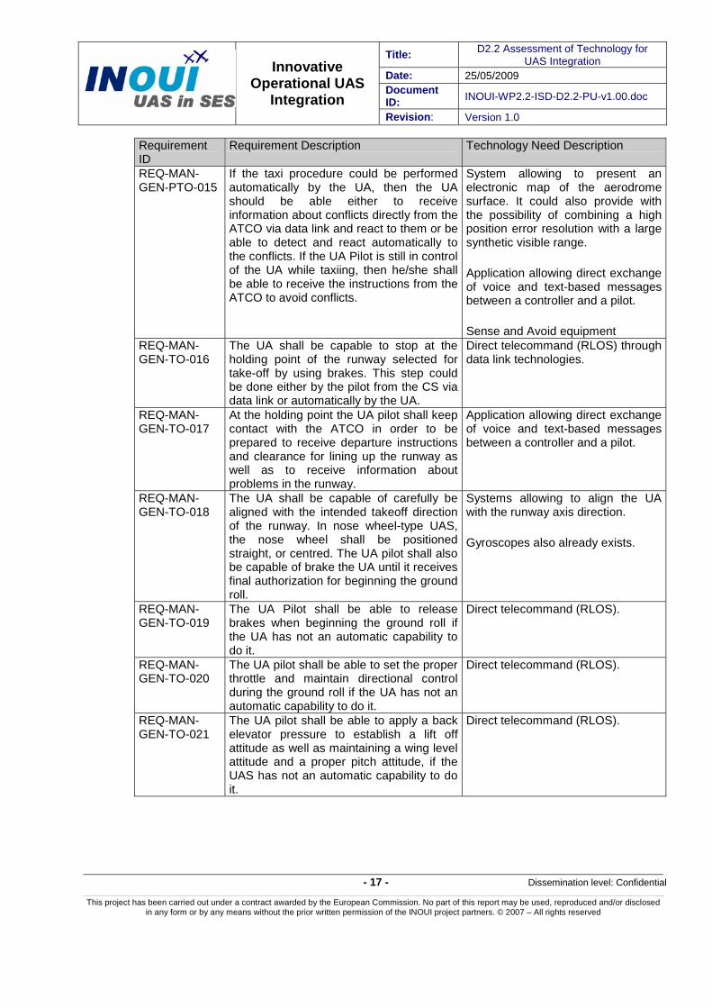
REQ-MAN-GEN-PTO-015
If the taxi procedure could be performed automatically by the UA, then the UA should be able either to receive information about conflicts directly from the ATCO via data link and react to them or be able to detect and react automatically to the conflicts. If the UA Pilot is still in control of the UA while taxiing, then he/she shall be able to receive the instructions from the ATCO to avoid conflicts.
System allowing to present an electronic map of the aerodrome surface. It could also provide with the possibility of combining a high position error resolution with a large synthetic visible range.
Application allowing direct exchange of voice and text-based messages between a controller and a pilot.
Sense and Avoid equipment REQ-MAN-GEN-TO-016
The UA shall be capable to stop at the holding point of the runway selected for take-off by using brakes. This step could be done either by the pilot from the CS via data link or automatically by the UA.
Direct telecommand (RLOS) through data link technologies.
REQ-MAN-GEN-TO-017
At the holding point the UA pilot shall keep contact with the ATCO in order to be prepared to receive departure instructions and clearance for lining up the runway as well as to receive information about problems in the runway.
Application allowing direct exchange of voice and text-based messages between a controller and a pilot.
REQ-MAN-GEN-TO-018
The UA shall be capable of carefully be aligned with the intended takeoff direction of the runway. In nose wheel-type UAS, the nose wheel shall be positioned straight, or centred. The UA pilot shall also be capable of brake the UA until it receives final authorization for beginning the ground roll.
Systems allowing to align the UA with the runway axis direction.
Gyroscopes also already exists.
REQ-MAN-GEN-TO-019
The UA Pilot shall be able to release brakes when beginning the ground roll if the UA has not an automatic capability to do it.
Direct telecommand (RLOS).
REQ-MAN-GEN-TO-020
The UA pilot shall be able to set the proper throttle and maintain directional control during the ground roll if the UA has not an automatic capability to do it.
Direct telecommand (RLOS).
REQ-MAN-GEN-TO-021
The UA pilot shall be able to apply a back elevator pressure to establish a lift off attitude as well as maintaining a wing level attitude and a proper pitch attitude, if the UAS has not an automatic capability to do it.
Direct telecommand (RLOS).
Title: D2.2 Assessment of Technology for UAS Integration
Date: 25/05/2009 Document ID: INOUI-WP2.2-ISD-D2.2-PU-v1.00.doc
Innovative Operational UAS
Integration Revision: Version 1.0
- 18 - Dissemination level: Confidential
This project has been carried out under a contract awarded by the European Commission. No part of this report may be used, reproduced and/or disclosed in any form or by any means without the prior written permission of the INOUI project partners. © 2007 – All rights reserved
Requirement ID
Requirement Description Technology Need Description
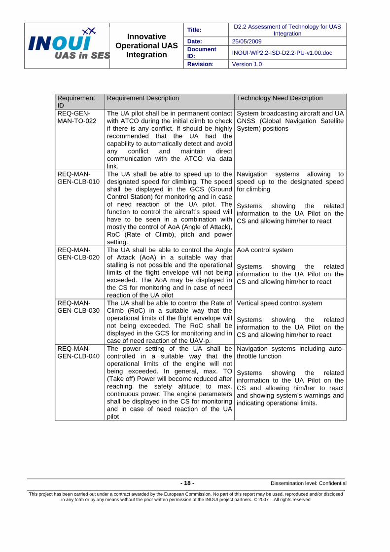
REQ-GEN-MAN-TO-022
The UA pilot shall be in permanent contact with ATCO during the initial climb to check if there is any conflict. If should be highly recommended that the UA had the capability to automatically detect and avoid any conflict and maintain direct communication with the ATCO via data link.
System broadcasting aircraft and UA GNSS (Global Navigation Satellite System) positions
REQ-MAN-GEN-CLB-010
The UA shall be able to speed up to the designated speed for climbing. The speed shall be displayed in the GCS (Ground Control Station) for monitoring and in case of need reaction of the UA pilot. The function to control the aircraft’s speed will have to be seen in a combination with mostly the control of AoA (Angle of Attack), RoC (Rate of Climb), pitch and power setting.
Navigation systems allowing to speed up to the designated speed for climbing
Systems showing the related information to the UA Pilot on the CS and allowing him/her to react
REQ-MAN-GEN-CLB-020
The UA shall be able to control the Angle of Attack (AoA) in a suitable way that stalling is not possible and the operational limits of the flight envelope will not being exceeded. The AoA may be displayed in the CS for monitoring and in case of need reaction of the UA pilot
AoA control system
Systems showing the related information to the UA Pilot on the CS and allowing him/her to react
REQ-MAN-GEN-CLB-030
The UA shall be able to control the Rate of Climb (RoC) in a suitable way that the operational limits of the flight envelope will not being exceeded. The RoC shall be displayed in the GCS for monitoring and in case of need reaction of the UAV-p.
Vertical speed control system
Systems showing the related information to the UA Pilot on the CS and allowing him/her to react
REQ-MAN-GEN-CLB-040
The power setting of the UA shall be controlled in a suitable way that the operational limits of the engine will not being exceeded. In general, max. TO (Take off) Power will become reduced after reaching the safety altitude to max. continuous power. The engine parameters shall be displayed in the CS for monitoring and in case of need reaction of the UA pilot
Navigation systems including auto-throttle function
Systems showing the related information to the UA Pilot on the CS and allowing him/her to react and showing system’s warnings and indicating operational limits.

Title: D2.2 Assessment of Technology for UAS Integration
Date: 25/05/2009 Document ID: INOUI-WP2.2-ISD-D2.2-PU-v1.00.doc
Innovative Operational UAS
Integration Revision: Version 1.0
- 19 - Dissemination level: Confidential
This project has been carried out under a contract awarded by the European Commission. No part of this report may be used, reproduced and/or disclosed in any form or by any means without the prior written permission of the INOUI project partners. © 2007 – All rights reserved
Requirement ID
Requirement Description Technology Need Description
REQ-MAN-GEN-CLB-050
If the UA is equipped with a variable pitch propeller, the pitch setting of the UA shall be controlled in a suitable way that the operational limits of the engine will not being exceeded. In general, the pitch of the propeller(s) will become reduced for cruising. The propeller’s parameters shall be displayed in the GCS for monitoring and in case of need reaction of the UAV-p.
Navigation system with auto-pitch function
Systems showing the related information to the UA Pilot on the CS and allowing him/her to react and showing system’s warnings and indicating operational limits.
REQ-MAN-GEN-CLB-060
The altitude of the UA must be controlled in a suitable way and must be displayed in the CS for monitoring and in case of need reaction of the UA pilot. As departure routes are mostly connected with a certain altitude, altitude keeping and monitoring becomes a high level requirement in controlled airspace.
Altimeter(s) and precise navigation systems
Systems showing the related information to the UA Pilot on the CS and allowing him/her to react
REQ-MAN-GEN-CLB-070
The UAS must have the ability to report the current position of the UA either if required in the departure instructions, or by reaching a compulsory reporting point, or on request by ATC (Air Traffic Control). This may be done by the UA pilot or by technical means of the UAS.
Navigation System
Systems showing the related information to the UA Pilot on the CS and allowing him/her to react
Communication System between ATC and UA Pilot
REQ-MAN-GEN-CLB-080
The UA must have the ability to climb in accordance with the departure instructions, and according the published routes. For this reason, this requirement contains also the compensation of cross wind vectors to keep the track.
System capable of to modifying the current flight conduction according the clearance.
Systems showing the related information to the UA Pilot on the CS and allowing him/her to react
REQ-MAN-GEN-CLB-090
The UA must have the ability to climb in accordance with required headings, what leads to the handling of information of a magnetic or gyroscopic compass.
Navigation systems with “proceed on heading” or “proceed on track” capabilities.
REQ-MAN-GEN-CLB-100
There must be means to display the UA position with respect to the horizontal and vertical limits of the airspace classes. Due to the airspace structure, there is the need to contact the related ANSP (Air Navigation Service Provider) by radio, switch different transponder codes and to communicate with different stations.
Radio(s) and Transponder(s) showing UA position
Systems showing the related information to the UA Pilot on the CS and allowing him/her to react
Communication System between ATC and UA Pilot

Title: D2.2 Assessment of Technology for UAS Integration
Date: 25/05/2009 Document ID: INOUI-WP2.2-ISD-D2.2-PU-v1.00.doc
Innovative Operational UAS
Integration Revision: Version 1.0
- 20 - Dissemination level: Confidential
This project has been carried out under a contract awarded by the European Commission. No part of this report may be used, reproduced and/or disclosed in any form or by any means without the prior written permission of the INOUI project partners. © 2007 – All rights reserved
Requirement ID
Requirement Description Technology Need Description
REQ-MAN-GEN-CLB-110
If equipped with a retractable gear, there must be means to move the gear, to display the status up / down / moving. Furthermore, failure modes should be detected, displayed, and emergency procedures should be engaged either as command of the GCS or automatically. Speed limits for moving out the gear should be kept or may be only ignored after warning.
Navigation system with auto gear function
Systems showing the related information to the UA Pilot on the CS and allowing him/her to react
REQ-MAN-GEN-CLB-120
If equipped with flaps, there must be means to move the flaps, to display the status up / down / moving / angles. Furthermore, failure modes should be detected, displayed, and emergency procedures should be engaged either as command of the GCS or automatically. Speed limits for moving out the flaps are to be kept or may be only ignored after warning. If engaging flaps will lead to a change of trim, there should be means to prevent excessive loads to the elevator’s actuators and /or to control the AoA to fly within the aircraft’s limits.
Navigation System with auto flap function
Systems showing the related information to the UA Pilot on the CS and allowing him/her to react
See also REQ-MAN-GEN-CLB-010 and REQ-MAN-GEN-CLB-020
REQ-MAN-GEN-CLB-130
The speed of the UA should be kept within the limits and be displayed in the GCS for monitoring and in case of need reaction of the UAV p. The function to control the aircraft’s speed will have to be seen in a combination with mostly the control of AoA, RoC, pitch and power setting. [See REQ-MAN-GEN-CLB-010]
See also: REQ-MAN-GEN-CLB-010 to REQ-MAN-GEN-CLB-050.
REQ-MAN-GEN-CLB-140
The power setting of the UA shall be controlled in a suitable way that the operational limits of the engine will not being exceeded. In general, max. TO Power will become reduced after reaching the safety altitude to max. continuous power. The engine parameters shall be displayed in the GCS for monitoring and in case of need reaction of the UAV-p. During climb, the constant monitoring of the engine’s limits for pressures and temperatures is essential, due to the AoA, low speeds and high power demands. [See also REQ-MAN-GEN-CLB-040]
See also: REQ-MAN-GEN-CLB-040

Title: D2.2 Assessment of Technology for UAS Integration
Date: 25/05/2009 Document ID: INOUI-WP2.2-ISD-D2.2-PU-v1.00.doc
Innovative Operational UAS
Integration Revision: Version 1.0
- 21 - Dissemination level: Confidential
This project has been carried out under a contract awarded by the European Commission. No part of this report may be used, reproduced and/or disclosed in any form or by any means without the prior written permission of the INOUI project partners. © 2007 – All rights reserved
Requirement ID
Requirement Description Technology Need Description
REQ-MAN-GEN-CLB-150
The Altitude of the UA on long lasting climb may effect the airspeed indication. For this reason, an altitude compensation of the airspeed is required for high altitude flights as well as for leaning combustion engines.
Systems allowing altitude compensation for Actuators Sensors Interface
Systems showing the related information to the UA Pilot on the CS and allowing him/her to react
REQ-MAN-GEN-CLB-160
Means to avoid collisions with other air traffic are required. This leads from procedural aids like semi circular flight altitudes, to active anti collision equipment.
Flight rule based assistance system using semi circular flight altitudes for planning
Sense & Avoid systems
Systems showing the related information to the UA Pilot on the CS and allowing him/her to react
REQ-MAN-GEN-ERT-010
The altitude of the UA must be controlled in a suitable way and must be displayed in the GCS for monitoring and in case of need reaction of the UAV-p. If RVSM (Reduced Vertical Separation Minima) operation is envisaged, the range of allowed altitude deviation is much more demanding as in areas without RVSM. [See also REQ-MAN-GEN-CLB-060]
See : REQ-MAN-GEN-CLB-060
REQ-MAN-GEN-ERT-020
The vertical speed of the UA must be controlled in a suitable way and must be displayed in the GCS for monitoring and in case of need reaction of the UAV-p. If steady en-route flying at a certain altitude is envisaged, the vertical speed should be zero and kept. For long distance cruise climbs the vertical speed will have to be controlled too.
See: REQ-MAN-GEN-CLB-030
REQ-MAN-GEN-ERT-030
After levelling out the aircraft, pitch and power setting will have to become reduced in accordance with the flight manual.
See: REQ-MAN-GEN-CLB-040 and See: REQ-MAN-GEN-CLB-050
REQ-MAN-GEN-ERT-040
The engine parameters shall be displayed in the GCS for monitoring and in case of need reaction of the UAV-p. [See also REQ-MAN-GEN-CLB-040 and REQ-MAN-GEN-CLB-140]
See: REQ-MAN-GEN-CLB-040
Title: D2.2 Assessment of Technology for UAS Integration
Date: 25/05/2009 Document ID: INOUI-WP2.2-ISD-D2.2-PU-v1.00.doc
Innovative Operational UAS
Integration Revision: Version 1.0
- 22 - Dissemination level: Confidential
This project has been carried out under a contract awarded by the European Commission. No part of this report may be used, reproduced and/or disclosed in any form or by any means without the prior written permission of the INOUI project partners. © 2007 – All rights reserved
Requirement ID
Requirement Description Technology Need Description
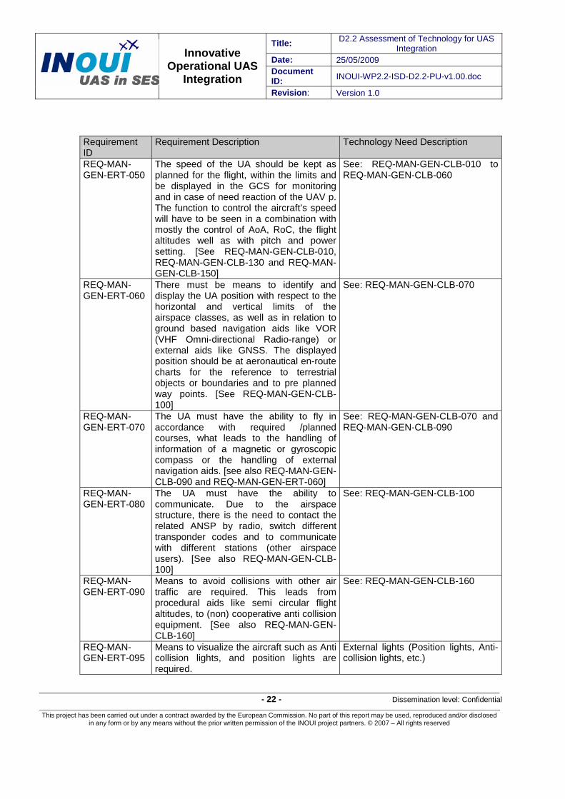
REQ-MAN-GEN-ERT-050
The speed of the UA should be kept as planned for the flight, within the limits and be displayed in the GCS for monitoring and in case of need reaction of the UAV p. The function to control the aircraft’s speed will have to be seen in a combination with mostly the control of AoA, RoC, the flight altitudes well as with pitch and power setting. [See REQ-MAN-GEN-CLB-010, REQ-MAN-GEN-CLB-130 and REQ-MAN-GEN-CLB-150]
See: REQ-MAN-GEN-CLB-010 to REQ-MAN-GEN-CLB-060
REQ-MAN-GEN-ERT-060
There must be means to identify and display the UA position with respect to the horizontal and vertical limits of the airspace classes, as well as in relation to ground based navigation aids like VOR (VHF Omni-directional Radio-range) or external aids like GNSS. The displayed position should be at aeronautical en-route charts for the reference to terrestrial objects or boundaries and to pre planned way points. [See REQ-MAN-GEN-CLB-100]
See: REQ-MAN-GEN-CLB-070
REQ-MAN-GEN-ERT-070
The UA must have the ability to fly in accordance with required /planned courses, what leads to the handling of information of a magnetic or gyroscopic compass or the handling of external navigation aids. [see also REQ-MAN-GEN-CLB-090 and REQ-MAN-GEN-ERT-060]
See: REQ-MAN-GEN-CLB-070 and REQ-MAN-GEN-CLB-090
REQ-MAN-GEN-ERT-080
The UA must have the ability to communicate. Due to the airspace structure, there is the need to contact the related ANSP by radio, switch different transponder codes and to communicate with different stations (other airspace users). [See also REQ-MAN-GEN-CLB-100]
See: REQ-MAN-GEN-CLB-100
REQ-MAN-GEN-ERT-090
Means to avoid collisions with other air traffic are required. This leads from procedural aids like semi circular flight altitudes, to (non) cooperative anti collision equipment. [See also REQ-MAN-GEN-CLB-160]
See: REQ-MAN-GEN-CLB-160
REQ-MAN-GEN-ERT-095
Means to visualize the aircraft such as Anti collision lights, and position lights are required.
External lights (Position lights, Anti-collision lights, etc.)

Title: D2.2 Assessment of Technology for UAS Integration
Date: 25/05/2009 Document ID: INOUI-WP2.2-ISD-D2.2-PU-v1.00.doc
Innovative Operational UAS
Integration Revision: Version 1.0
- 23 - Dissemination level: Confidential
This project has been carried out under a contract awarded by the European Commission. No part of this report may be used, reproduced and/or disclosed in any form or by any means without the prior written permission of the INOUI project partners. © 2007 – All rights reserved
Requirement ID
Requirement Description Technology Need Description
REQ-MAN-GEN-ERT-100
As most of the UA are due to their flight management computer systems are to be seen as All Electric Aircraft, means to identify and visualize thunderstorms at the CS will be mandatory. There should be the possibility to either by command of the CS or by technical means to avoid those atmospherically conditions which may endanger the safe conduction of the flight and in case of accidents also third parties.
Systems showing the related meteorological information to the UA Pilot on the CS and allowing him/her to react and to avoid bad weather.
Communication System between ATC and UA Pilot
REQ-MAN-GEN-ERT-110
Due to possible clear air turbulences, the speed of the aircraft may need to be reduced. The airspeed changes of the UA should be taken into account regarding their effect concerning possible changes to the flight plan, and be displayed in the CS for monitoring and in case of need reaction of the UA pilot.
Navigation system allowing to reduce speed when necessary (specially due to clear air turbulences)
Systems showing the related information to the UA Pilot on the CS and allowing him/her to react and to determine when a change in the flight plan is necessary
REQ-MAN-GEN-DSC-010
The UA shall be able to control the designated speed for descending. The speed shall be displayed in the GCS for monitoring and in case of need reaction of the UAV p. The function to control the aircraft’s speed will have to be seen in a combination with the control of AoA, RoC, pitch and power setting [See also REQ-MAN-GEN-CLB-010].
See also: REQ-MAN-GEN-CLB-010
REQ-MAN-GEN-DSC-020
The UA shall be able to control the Angle of Attack (AoA) in a suitable way that he operational limits will not being exceeded. The AoA may be displayed in the GCS for monitoring and in case of need reaction of the UAV p [See also REQ-MAN-GEN-CLB-020].
See also: REQ-MAN-GEN-CLB-020
REQ-MAN-GEN-DSC-030
The UA shall be able to control the Rate of Descent (DoC) in a suitable way that the operational limits will not being exceeded. The DoC shall be displayed in the GCS for monitoring and in case of need reaction [See also REQ-MAN-GEN-CLB-030].
See also: REQ-MAN-GEN-CLB-030

Title: D2.2 Assessment of Technology for UAS Integration
Date: 25/05/2009 Document ID: INOUI-WP2.2-ISD-D2.2-PU-v1.00.doc
Innovative Operational UAS
Integration Revision: Version 1.0
- 24 - Dissemination level: Confidential
This project has been carried out under a contract awarded by the European Commission. No part of this report may be used, reproduced and/or disclosed in any form or by any means without the prior written permission of the INOUI project partners. © 2007 – All rights reserved
Requirement ID
Requirement Description Technology Need Description
REQ-MAN-GEN-DSC-040
The power setting of the UA shall be controlled in a suitable way that the operational limits of the engine will not being exceeded. In general, the power setting for cruise will become reduced because of the additional potential energy during the descent phase. (This may be done down to “flight idle”).The engine parameters shall be displayed in the GCS for monitoring and in case of need reaction of the UAV-p [See also REQ-MAN-GEN-CLB-040, REQ-MAN-GEN-CLB-140 and REQ-MAN-GEN-ERT-040].
See also: REQ-MAN-GEN-CLB-040
REQ-MAN-GEN-DSC-050
If the UA is equipped with a variable pitch propeller, the pitch setting of the UA shall be controlled in a suitable way that the operational limits of the engine will not being exceeded. The pitch of the propeller(s) may be changed for descending. The propeller’s parameters shall be displayed in the GCS as well as related engine parameters like manifold pressure for monitoring and in case of need reaction of the UAV-p [See REQ-MAN-GEN-CLB-010, REQ-MAN-GEN-CLB-130, REQ-MAN-GEN-CLB-150 and REQ-MAN-GEN-ERT-050].
See also: REQ-MAN-GEN-CLB-050
REQ-MAN-GEN-DSC-060
The altitude of the UA must be controlled in a suitable way and must be displayed in the GCS for monitoring and in case of need reaction of the UAV-p. As descending is connected with minimized altitude tolerances, exact altitude controlling and monitoring becomes on of the highest level requirement during the descent phase [See also REQ-MAN-GEN-CLB-060].
See also: REQ-MAN-GEN-CLB-060
REQ-MAN-GEN-DSC-070
The UAS must have the ability to report its current position on request by ATC. This may be done by the UAV-p or by technical means of the UAS [See also REQ-MAN-GEN-CLB-070].
See also: REQ-MAN-GEN-CLB-070
REQ-MAN-GEN-DSC-080
The UA must have the ability to descent in accordance with the ATC instructions. This requirement contains also the compensation of cross wind vectors to keep the track [See also REQ-MAN-GEN-CLB-080].
See also: REQ-MAN-GEN-CLB-080

Title: D2.2 Assessment of Technology for UAS Integration
Date: 25/05/2009 Document ID: INOUI-WP2.2-ISD-D2.2-PU-v1.00.doc
Innovative Operational UAS
Integration Revision: Version 1.0
- 25 - Dissemination level: Confidential
This project has been carried out under a contract awarded by the European Commission. No part of this report may be used, reproduced and/or disclosed in any form or by any means without the prior written permission of the INOUI project partners. © 2007 – All rights reserved
Requirement ID
Requirement Description Technology Need Description
REQ-MAN-GEN-DSC-090
The UA must have the ability to descent in accordance with required headings, what leads to the handling of information of a magnetic or gyroscopic compass [See also REQ-MAN-GEN-CLB-090].
See also: REQ-MAN-GEN-CLB-090
REQ-MAN-GEN-DSC-100
There must be means to display the UA position with respect to the horizontal and vertical limits of the airspace classes. Due to the airspace structure, there is the need to contact the related ANSP by radio, switch different transponder codes and to communicate with different stations [See also REQ-MAN-GEN-CLB-100].
See also: REQ-MAN-GEN-CLB-100
REQ-MAN-GEN-DSC-110
If equipped with a retractable gear, there must be means to move the gear, to display the status up / down / moving. Furthermore, failure modes should be detected, displayed, and emergency procedures should be engaged either as command of the GCS or automatically. Speed limits for moving out the gear should be kept or may be only ignored after warning [See also REQ-MAN-GEN-CLB-110].
See also: REQ-MAN-GEN-CLB-110
REQ-MAN-GEN-DSC-120
If equipped with flaps, there must be means to move the flaps, to display the status up / down / moving / angles. Furthermore, failure modes should be detected, displayed, and emergency procedures should be engaged either as command of the GCS or automatically. Speed limits for moving out the flaps are to be kept or may be only ignored after warning. If engaging flaps will lead to a change of trim, there should be means to prevent excessive loads to the elevator’s actuators and /or to control the AoA to fly within the aircraft’s limits [see also REQ-MAN-GEN-CLB-120].
See also: REQ-MAN-GEN-CLB-120
REQ-MAN-GEN-DSC-130
The speed of the UA should be kept within the limits and be displayed in the GCS for monitoring and in case of need reaction of the UAV p. The function to control the aircraft’s speed will have to be seen in a combination with mostly the control of AoA, RoC, pitch and power setting and flaps. [see REQ-MAN-GEN-DSC-010].
See also: REQ-MAN-GEN-CLB-130. See also: REQ-MAN-GEN-CLB-140.

Title: D2.2 Assessment of Technology for UAS Integration
Date: 25/05/2009 Document ID: INOUI-WP2.2-ISD-D2.2-PU-v1.00.doc
Innovative Operational UAS
Integration Revision: Version 1.0
- 26 - Dissemination level: Confidential
This project has been carried out under a contract awarded by the European Commission. No part of this report may be used, reproduced and/or disclosed in any form or by any means without the prior written permission of the INOUI project partners. © 2007 – All rights reserved
Requirement ID
Requirement Description Technology Need Description
REQ-MAN-GEN-DSC-140
As most of the UA are due to their flight management computer systems are to be seen as All Electric Aircraft, means to identify and visualize thunderstorms at the GCS will be mandatory. There should be the possibility to either by command of the GCS or by technical means to avoid those atmospherically conditions which may endanger the safe conduction of the flight and in case of accidents also third parties.
See also: REQ-MAN-GEN-ERT-100
REQ-MAN-GEN-DSC-150
Due to possible clear air turbulences, the speed of the aircraft may need to be reduced. The airspeed changes of the UA should be taken into account regarding their effect concerning possible changes to the flight plan, and be displayed in the GCS for monitoring and in case of need reaction of the UAV p.
See also: REQ-MAN-GEN-ERT-110
REQ-MAN-GEN-DSC-155
Approaching a controlled airport allows to become informed about the current weather situation by using the ATIS information (Automated terminal information service). This information is currently updated. As ATIS messages are given at the aerodrome’s VOR frequency, a VOR receiver is required to participate of this service.
Systems allowing reception of ATIS information (VOR receivers) on the CS
REQ-MAN-GEN-DSC-160
Means to avoid collisions with other air traffic are required. This leads from procedural aids like semi circular flight altitudes, to active anti collision equipment ACAS or TCAS. [See also REQ-MAN-GEN-CLB-160].
See also: REQ-MAN-GEN-CLB-160
REQ-MAN-GEN-DSC-170
Means to visualize the aircraft such as Anti collision lights, and position lights are required. [See also REQ-MAN-GEN-ERT-090].
See also: REQ-MAN-GEN-ERT-095
REQ-MAN-GEN-DSC-180
The UA must have the ability to communicate. Due to the airspace structure, there is the need to contact the related ANSP by radio, switch different transponder codes and to communicate with different stations (other airspace users). As the envisaged landing on a controlled airport requires a clearance, the initial call will have to be performed prior to enter the CTR. [See also REQ-MAN-GEN-CLB-100, REQ-MAN-GEN-ERT-080]
See also: REQ-MAN-GEN-CLB-100, REQ-MAN-GEN-ERT-080

Title: D2.2 Assessment of Technology for UAS Integration
Date: 25/05/2009 Document ID: INOUI-WP2.2-ISD-D2.2-PU-v1.00.doc
Innovative Operational UAS
Integration Revision: Version 1.0
- 27 - Dissemination level: Confidential
This project has been carried out under a contract awarded by the European Commission. No part of this report may be used, reproduced and/or disclosed in any form or by any means without the prior written permission of the INOUI project partners. © 2007 – All rights reserved
Requirement ID
Requirement Description Technology Need Description
REQ-MAN-GEN-APP-001
The UA shall be capable to initiate a request for landing instruction to the relevant air traffic control station. This step could be done either by the pilot from the CS via data link or automatically by the UA.
Communications systems between the UA pilot and ATC
REQ-MAN-GEN-APP-002
The UA shall be capable to fly along the instructed cleared track for the approach. The UA should maintain a certain level of required navigation performance integrity. The level of integrity must be available to both pilot and controller. This step could be done either by the pilot from the CS via data link or automatically by the UA.
Navigation system capable of flying along the cleared track and capable of maintaining a required level of navigation performance integrity.
Systems showing the related information to the UA Pilot on the CS and allowing him/her to react.
Tranponder(s) system(s)
Communications systems between the UA pilot and ATC
REQ-MAN-GEN-APP-003
The ground control station pilot should be capable of receiving landing airport information. There should be a requirement for the Ground Control Station to be able to receive and handle near real time data form the automatic terminal information system (ATIS)
Communications systems between the UA pilot and ATC
Systems capable of receiving ATIS information (VOR receiver).
REQ-MAN-GEN-APP-004
Both the UA vehicle as well as the Ground control pilot should be capable to detect any possible threat from runway incursion. In addition the airport information system should alert the UA pilot of possible threats not identified by the UAS.
Communications systems between the UA pilot and ATC
System allowing to present an electronic map of the aerodrome surface. It could also provide with the possibility of combining a high position error resolution with a large synthetic visible range.
Systems capable of receiving ATIS information (VOR receiver).
REQ-MAN-GEN-APP-005
The UA must have sensors to detect possible runway incursions. An alert shall be provided to the ground control operator to take appropriate action if and when required
System allowing to present an electronic map of the aerodrome surface. It could also provide with the possibility of combining a high position error resolution with a large synthetic visible range.
Sense & Avoid systems

Title: D2.2 Assessment of Technology for UAS Integration
Date: 25/05/2009 Document ID: INOUI-WP2.2-ISD-D2.2-PU-v1.00.doc
Innovative Operational UAS
Integration Revision: Version 1.0
- 28 - Dissemination level: Confidential
This project has been carried out under a contract awarded by the European Commission. No part of this report may be used, reproduced and/or disclosed in any form or by any means without the prior written permission of the INOUI project partners. © 2007 – All rights reserved
Requirement ID
Requirement Description Technology Need Description
REQ-MAN-GEN-APP-006
The UA shall be capable to configure for final approach. The appropriate landing devices must be deployed. This step could be done either by the pilot from the CS via data link or automatically by the UA.
Navigation systems capable of configure the UA for final approach.
Systems showing the related information to the UA Pilot on the CS and allowing him/her to react.
REQ-MAN-GEN-LAN-001
The UA shall be capable to touch down at the defined runway touch down point. The UA should touch down at the appropriate speed and angle of attack. This step could be done either by the pilot from the CS via data link or automatically by the UA.
Navigation systems capable of touching down at the defined runway touch down point.
Systems showing the related information to the UA Pilot on the CS and allowing him/her to react.
REQ-MAN-GEN-LAN-002
The UA shall be capable to reduce touch down speed by using brakes, either hydraulic or aerodynamic brakes. This step could be done either by the pilot from the CS via data link or automatically by the UA.
Navigation systems capable of reduce touch down speed.
Systems showing the related information to the UA Pilot on the CS and allowing him/her to react.
REQ-MAN-GEN-LAN-003
The UA shall be capable to maintain enough speed to taxi after reducing its speed from touch down. This step could be done either by the pilot from the CS via data link or automatically by the UA.
Navigation systems capable of maintaining enough speed to taxi after reducing its speed from touch down
Systems showing the related information to the UA Pilot on the CS and allowing him/her to react.
REQ-MAN-GEN-LAN-004
The UA shall be steerable and directed towards the defined taxi way. This step is more likely to be done by the pilot from the CS via data link, by means of appropriate ground handling commands.
Navigation systems capable of steer and direct the UA towards the taxi way
Systems showing the related information to the UA Pilot on the CS and allowing him/her to react.
System allowing to present an electronic map of the aerodrome surface. It could also provide with the possibility of combining a high position error resolution with a large synthetic visible range.

Title: D2.2 Assessment of Technology for UAS Integration
Date: 25/05/2009 Document ID: INOUI-WP2.2-ISD-D2.2-PU-v1.00.doc
Innovative Operational UAS
Integration Revision: Version 1.0
- 29 - Dissemination level: Confidential
This project has been carried out under a contract awarded by the European Commission. No part of this report may be used, reproduced and/or disclosed in any form or by any means without the prior written permission of the INOUI project partners. © 2007 – All rights reserved
Requirement ID
Requirement Description Technology Need Description
REQ-MAN-GEN-LTX-001
The UA shall be capable to follow the taxi instructions received by air traffic control. Taxiing to holding position could be done either by the pilot from the CS via data link or automatically by the UA. The ground handling control of the UA should allow for near 180º movement on the spot to steer the UA to holding position efficiently.
Navigation systems capable of follow taxi instructions
Communications systems between the UA pilot and ATC.
System allowing to present an electronic map of the aerodrome surface. It could also provide with the possibility of combining a high position error resolution with a large synthetic visible range.
REQ-MAN-GEN-LTX-002
The UA shall be capable to conduct follow me procedures. This step could be done either by the pilot from the CS via data link or automatically by the UA. If this step is to be carried out automatically by the UAS then special sensor and technology must be equipped on board the UAS. Otherwise the pilot would command and control the aircraft to comply with the follow me procedures.
Navigation systems capable of performing follow me procedures.
Systems showing the related information to the UA Pilot on the CS and allowing him/her to react.
System allowing to present an electronic map of the aerodrome surface. It could also provide with the possibility of combining a high position error resolution with a large synthetic visible range.
REQ-MAN-GEN-LTX-003
The UA shall be capable to complete the follow me procedures to arrive and stop at the required parking position assigned by traffic control.
Navigation systems capable of completing follow me procedures to arrive and stop at the parking position.
Systems showing the related information to the UA Pilot on the CS and allowing him/her to react.
System allowing to present an electronic map of the aerodrome surface. It could also provide with the possibility of combining a high position error resolution with a large synthetic visible range.

Title: D2.2 Assessment of Technology for UAS Integration
Date: 25/05/2009 Document ID: INOUI-WP2.2-ISD-D2.2-PU-v1.00.doc
Innovative Operational UAS
Integration Revision: Version 1.0
- 30 - Dissemination level: Confidential
This project has been carried out under a contract awarded by the European Commission. No part of this report may be used, reproduced and/or disclosed in any form or by any means without the prior written permission of the INOUI project partners. © 2007 – All rights reserved
Requirement ID
Requirement Description Technology Need Description
REQ-MAN-GEN-LTX-004
The UA shall be capable to stop at the parking position within some accuracy by using its ground handling controls. This step could be done either by the pilot from the CS via data link or automatically by the UA.
Navigation systems capable of stopping the UA at the parking position.
Systems showing the related information to the UA Pilot on the CS and allowing him/her to react.
System allowing to present an electronic map of the aerodrome surface. It could also provide with the possibility of combining a high position error resolution with a large synthetic visible range.
REQ-MAN-GEN-LTX-006
The UA shall be powered down after mission completion and once it is on its parking position. This step could be done either by the pilot from the CS via data link or automatically by the UA.
System capable of powering down the UA.
REQ-MAN-GEN-LTX-007
The UA shall be checked after power down for any structural damage or any possible malfunctions. This step should be done the UAS crew.
Monitoring system onboard the UA capable of check the onboard systems and transmit system malfunctions to the UA pilot.
2.3 Surveillance/Observation and Cargo Flight Applications Particularities
As mentioned in INOUI “D1.3 Proposal for the integration of UAS into the civil Airspace” surveillance/observation and cargo flight applications may be conducted using a rotary wing UAS. Please note that some of the technical requirements such as communication with ATCO will be the same as for fixed wing UAS and as such, only requirements for rotary wing UAS are given in this section.

Title: D2.2 Assessment of Technology for UAS Integration
Date: 25/05/2009 Document ID: INOUI-WP2.2-ISD-D2.2-PU-v1.00.doc
Innovative Operational UAS
Integration Revision: Version 1.0
- 31 - Dissemination level: Confidential
This project has been carried out under a contract awarded by the European Commission. No part of this report may be used, reproduced and/or disclosed in any form or by any means without the prior written permission of the INOUI project partners. © 2007 – All rights reserved
Table 2-2 UAS Technology Need Description for Requirements Identified – Surveillance/Observation and Cargo Flight Applications
Requirement ID
Requirement Description Technology Need Description
REQ-MAN-RWU-TAX-001
When performing a taxi manoeuvre, the UA shall be controlled in a way that an improper airspeed control and erratic movement over the surface is avoided.
Navigation system capable of performing taxi manoeuvre for rotary wing UA, controlling improper airspeed and erratic movement
Automatic / manual surface guidance control system with speed and turn limits.
REQ-MAN-RWU-TAX-002
When performing an air taxi or surface taxi manoeuvre, the UA shall be controlled in a way that excessive heading changes are avoided.
Navigation system capable of performing air taxi or surface taxi manoeuvre controlling heading changes for rotary wing UA
Automatic / manual surface guidance control system with speed and turn limits.
REQ-MAN-RWU-TAX-003
When performing an air taxi or surface taxi manoeuvre, the UA shall maintain proper altitude and power setting.
Navigation system capable of performing surface taxi manoeuvre maintaining altitude and power setting for rotary wing UA.
Automatic / manual surface guidance control system with speed and turn limits.
REQ-MAN-RWU-TAX-004
When performing an air taxi or surface taxi manoeuvre, the UA shall avoid flying in a crosswind that could lead to a loss of tail rotor effectiveness
Navigation system capable of performing air or surface taxi manoeuvre avoiding crosswind for a rotary wing UA.
Sensors capable of sense crosswind and systems capable of transmitting information to UA pilot and allowing him/her to react.
REQ-MAN-RWU-TO-005
When performing a vertical take-off to a hover the control of the vertical ascension shall be maintained in order to gain too much altitude.
Navigation system capable of controlling of the vertical ascension in vertical take-off for a rotary wing UA.
Automatic / manual surface guidance control system with speed and turn limits.
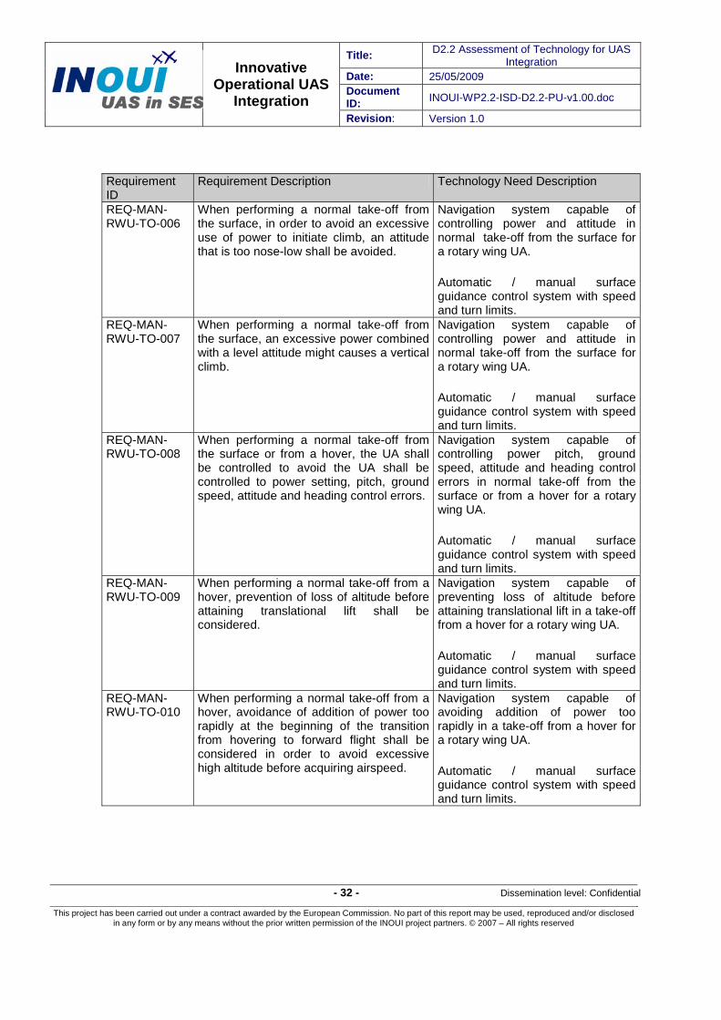
Title: D2.2 Assessment of Technology for UAS Integration
Date: 25/05/2009 Document ID: INOUI-WP2.2-ISD-D2.2-PU-v1.00.doc
Innovative Operational UAS
Integration Revision: Version 1.0
- 32 - Dissemination level: Confidential
This project has been carried out under a contract awarded by the European Commission. No part of this report may be used, reproduced and/or disclosed in any form or by any means without the prior written permission of the INOUI project partners. © 2007 – All rights reserved
Requirement ID
Requirement Description Technology Need Description
REQ-MAN-RWU-TO-006
When performing a normal take-off from the surface, in order to avoid an excessive use of power to initiate climb, an attitude that is too nose-low shall be avoided.
Navigation system capable of controlling power and attitude in normal take-off from the surface for a rotary wing UA.
Automatic / manual surface guidance control system with speed and turn limits.
REQ-MAN-RWU-TO-007
When performing a normal take-off from the surface, an excessive power combined with a level attitude might causes a vertical climb.
Navigation system capable of controlling power and attitude in normal take-off from the surface for a rotary wing UA.
Automatic / manual surface guidance control system with speed and turn limits.
REQ-MAN-RWU-TO-008
When performing a normal take-off from the surface or from a hover, the UA shall be controlled to avoid the UA shall be controlled to power setting, pitch, ground speed, attitude and heading control errors.
Navigation system capable of controlling power pitch, ground speed, attitude and heading control errors in normal take-off from the surface or from a hover for a rotary wing UA.
Automatic / manual surface guidance control system with speed and turn limits.
REQ-MAN-RWU-TO-009
When performing a normal take-off from a hover, prevention of loss of altitude before attaining translational lift shall be considered.
Navigation system capable of preventing loss of altitude before attaining translational lift in a take-off from a hover for a rotary wing UA.
Automatic / manual surface guidance control system with speed and turn limits.
REQ-MAN-RWU-TO-010
When performing a normal take-off from a hover, avoidance of addition of power too rapidly at the beginning of the transition from hovering to forward flight shall be considered in order to avoid excessive high altitude before acquiring airspeed.
Navigation system capable of avoiding addition of power too rapidly in a take-off from a hover for a rotary wing UA.
Automatic / manual surface guidance control system with speed and turn limits.

Title: D2.2 Assessment of Technology for UAS Integration
Date: 25/05/2009 Document ID: INOUI-WP2.2-ISD-D2.2-PU-v1.00.doc
Innovative Operational UAS
Integration Revision: Version 1.0
- 33 - Dissemination level: Confidential
This project has been carried out under a contract awarded by the European Commission. No part of this report may be used, reproduced and/or disclosed in any form or by any means without the prior written permission of the INOUI project partners. © 2007 – All rights reserved
Requirement ID
Requirement Description Technology Need Description
REQ-MAN-RWU-CLB-011
When performing a normal climb manoeuvre, the UA shall be controlled in a way that proper power and airspeed is maintained
Navigation system capable of maintaining power and airspeed in a normal climb for a rotary wing UA.
Automatic / manual surface guidance control system with speed and turn limits.
REQ-MAN-RWU-CRF-012
When performing a hovering manoeuvre a hover too high leading to a hazardous flight condition or a hover too low resulting in occasional touchdown shall be avoided.
Navigation system capable of avoiding hovering too high or too low in a hovering manoeuvre for a rotary wing UA.
Automatic / manual surface guidance control system with speed and turn limits.
REQ-MAN-RWU-CRF-013
When performing a Hovering – Forward, sideward or rearward flight manoeuvres groundspeed, altitude and heading shall be maintained.
Navigation system capable of maintaining groundspeed, altitude and heading in a hovering manoeuvre for a rotary wing UA.
Automatic / manual surface guidance control system with speed and turn limits.
REQ-MAN-RWU-CRF-014
When performing a Straight and level flight, constant altitude and heading shall be maintained.
Navigation system capable of maintaining constant altitude and heading in a straight and level flight for a rotary wing UA.
Automatic / manual surface guidance control system with speed and turn limits.
REQ-MAN-RWU-DSC-015
When performing a descent manoeuvre a constant angle of descent shall be maintained.
Navigation system capable of maintaining a constant angle of descent in a descent manoeuvre for a rotary wing UA.
Automatic / manual surface guidance control system with speed and turn limits.
REQ-MAN-RWU-APP-016
When performing a normal approach to hover and a steep approach to a hover, the UA shall be controlled in a way that proper power setting and angle of descent is maintained.
Navigation system capable of maintaining power setting and angle of descent in an approach manoeuvre for a rotary wing UA.
Automatic / manual surface guidance control system with speed and turn limits.
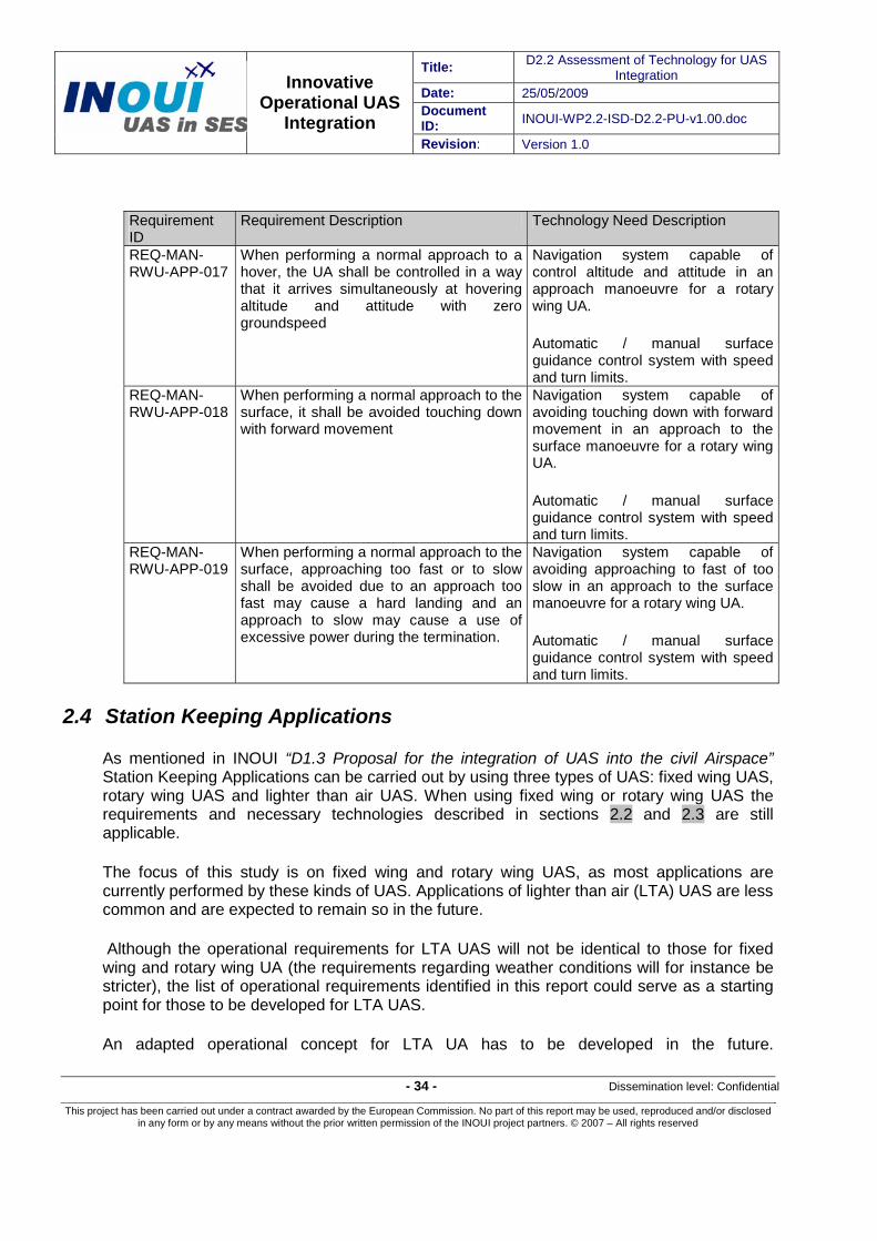
Title: D2.2 Assessment of Technology for UAS Integration
Date: 25/05/2009 Document ID: INOUI-WP2.2-ISD-D2.2-PU-v1.00.doc
Innovative Operational UAS
Integration Revision: Version 1.0
- 34 - Dissemination level: Confidential
This project has been carried out under a contract awarded by the European Commission. No part of this report may be used, reproduced and/or disclosed in any form or by any means without the prior written permission of the INOUI project partners. © 2007 – All rights reserved
Requirement ID
Requirement Description Technology Need Description
REQ-MAN-RWU-APP-017
When performing a normal approach to a hover, the UA shall be controlled in a way that it arrives simultaneously at hovering altitude and attitude with zero groundspeed
Navigation system capable of control altitude and attitude in an approach manoeuvre for a rotary wing UA.
Automatic / manual surface guidance control system with speed and turn limits.
REQ-MAN-RWU-APP-018
When performing a normal approach to the surface, it shall be avoided touching down with forward movement
Navigation system capable of avoiding touching down with forward movement in an approach to the surface manoeuvre for a rotary wing UA.
Automatic / manual surface guidance control system with speed and turn limits.
REQ-MAN-RWU-APP-019
When performing a normal approach to the surface, approaching too fast or to slow shall be avoided due to an approach too fast may cause a hard landing and an approach to slow may cause a use of excessive power during the termination.
Navigation system capable of avoiding approaching to fast of too slow in an approach to the surface manoeuvre for a rotary wing UA.
Automatic / manual surface guidance control system with speed and turn limits.
2.4 Station Keeping Applications
As mentioned in INOUI “D1.3 Proposal for the integration of UAS into the civil Airspace” Station Keeping Applications can be carried out by using three types of UAS: fixed wing UAS, rotary wing UAS and lighter than air UAS. When using fixed wing or rotary wing UAS the requirements and necessary technologies described in sections 2.2 and 2.3 are still applicable.
The focus of this study is on fixed wing and rotary wing UAS, as most applications are currently performed by these kinds of UAS. Applications of lighter than air (LTA) UAS are less common and are expected to remain so in the future.
Although the operational requirements for LTA UAS will not be identical to those for fixed wing and rotary wing UA (the requirements regarding weather conditions will for instance be stricter), the list of operational requirements identified in this report could serve as a starting point for those to be developed for LTA UAS.
An adapted operational concept for LTA UA has to be developed in the future.

Title: D2.2 Assessment of Technology for UAS Integration
Date: 25/05/2009 Document ID: INOUI-WP2.2-ISD-D2.2-PU-v1.00.doc
Innovative Operational UAS
Integration Revision: Version 1.0
- 35 - Dissemination level: Confidential
This project has been carried out under a contract awarded by the European Commission. No part of this report may be used, reproduced and/or disclosed in any form or by any means without the prior written permission of the INOUI project partners. © 2007 – All rights reserved
3 ATM Technology Needs 3.1 General
SESAR brings a new dimension to European ATM which has a wide effect on all airspace users including UAS.
The SESAR programme is the European Air Traffic Management (ATM) modernisation programme. It will combine technological, economic and regulatory aspects and will use the Single European Sky (SES) legislation to synchronise the plans and actions of the different stakeholders and federate resources for the development and implementation of the required improvements throughout Europe, in both airborne and ground systems.
The SESAR Consortium, and associated partners have agreed on the Master Plan representing the fundamental coordination tool for all future ATM activities. The SESAR Master Plan addresses the future of ATM in Europe over the next decades and forms the basis for the work programme of SESAR including for the implementation actions during the period 2008-2013.
The SESAR Master Plan establishes the R&D and deployment roadmaps for Operational Evolutions, Enabler Development & Deployment and Supporting Changes (e.g. safety, environment, etc.) with the common goal to implement the ATM Target Concept. It is important that the core components of the ATM Target Concept are implemented timely and consistently at European network level to enable full benefits.
The ATM Target Concept describes the main areas and directions of progress to be made. The specific and detailed changes (called “Operational Improvements [OI] steps”) required to transition from today’s system have been structured in a series of evolving ATM Service Levels (0-5)1 and organized in three Implementation Packages depending upon the date at which the corresponding capability can become operational (Initial Operational Capability (IOC) date):
IP1 – Implementation Package 1 (short-term: IOC dates up to 2012) - Covers ATM Service Levels 0 and 1.
IP2 – Implementation Package 2 (medium term: IOC dates in the period 2013-2019) - Covers ATM Service Levels 2 and 3.
IP3 – Implementation Package 3 (long term: IOC dates from 2020 onwards) - Covers ATM Service Level 4 and 5.
Throughout the SESAR Concept, techniques are described which are based on new capabilities and automation in the air and on the ground.
1 The notion of ATM capability levels had already been introduced in SESAR Deliverable 3 - The ATM Target Concept, it was translated into six levels of service in SESAR Deliverable 5 - The SESAR Master Plan.

Title: D2.2 Assessment of Technology for UAS Integration
Date: 25/05/2009 Document ID: INOUI-WP2.2-ISD-D2.2-PU-v1.00.doc
Innovative Operational UAS
Integration Revision: Version 1.0
- 36 - Dissemination level: Confidential
This project has been carried out under a contract awarded by the European Commission. No part of this report may be used, reproduced and/or disclosed in any form or by any means without the prior written permission of the INOUI project partners. © 2007 – All rights reserved
Four different levels are defined to describe the on-going deployment of progressively more advanced ATM systems for aircraft, ground systems and airports. To fly in managed airspace aircraft have to reach a certain aircraft capability level by 2020. For scheduled airlines and business aviation it has been assumed that aircraft will be equipped in order to comply with the ATM capability level-3 (Trajectory Sharing meeting ATM requirements; Avionics with Vertical Navigation Performance capability; multiple Required Time of Arrival (RTA) and Airborne Separation capability) by 2020. For General Aviation it has been assumed that General Aviation (GA) aircraft will be equipped with only ATM capability level-1 (ADS-B/out (position/aircraft/met data); Avionics with 2D-RNP (Required Navigation Performance), vertical constraint management and a single RTA; Data link: Event reporting/Intent sharing) by 2020.
These capability levels provide a convenient means to link many of the operational concepts to an easily defined and supportable implementation timeframe as well as providing an understanding of some of the key dependencies within and between concepts. ATM ground systems will be designed to take full advantage of each succeeding aircraft ATM Capability Level, while still accommodating those of a lower level.
It is recognised that some aircraft will have a range of capabilities ahead of the times indicated. These capabilities will be utilised whenever possible.
ATM-1 consists of such systems delivered up to the mid-term (2013) and which largely have today’s capabilities such as: ADS-B/out, controlled time management (single RTA), 2D-RNP, vertical and longitudinal constraint management, and, on the ground, collaborative planning applications and automatic data sharing.
ATM-2 consists of systems starting to be deployed from 2013 onwards, having a range of new capabilities, but which do not meet the full 2020 needs. Such new capabilities will include: cooperative surveillance (ADS-B/in), Controller Pilot Data Link Communication (CPDLC) and Aeronautical Information Service/ Meteorological (AIS/MET) Data link, airborne spacing/sequencing and merging, runway incursion alert systems, and information of all aircraft/vehicles shown on moving map displays.
ATM-3 defines those main capabilities that are required by the key SESAR date of 2020. In addition to those above, these capabilities will include: trajectory sharing air/ground and ground/ground, multiple time constraint management, vertical navigation performance requirements, cooperative separation functions, and taxiway conflict alerts.
ATM-4 consists of the very advanced capabilities that potentially offer the means to achieve the SESAR goals, in particular the very high-end capacity target. The timeframe for initial availability and progressive fleet equipage is in the range 2025 and beyond depending on the specific capability. ATM-4 will include: trajectory sharing air/air, MET data sharing, longitudinal navigation performance requirements, and self separation.

Title: D2.2 Assessment of Technology for UAS Integration
Date: 25/05/2009 Document ID: INOUI-WP2.2-ISD-D2.2-PU-v1.00.doc
Innovative Operational UAS
Integration Revision: Version 1.0
- 37 - Dissemination level: Confidential
This project has been carried out under a contract awarded by the European Commission. No part of this report may be used, reproduced and/or disclosed in any form or by any means without the prior written permission of the INOUI project partners. © 2007 – All rights reserved
ATM-0 covers all those that do not meet ATM-1 but which may still need to be accommodated.
Several technological enablers in communications, navigation and surveillance (CNS) are mentioned for each ATM capability level and thus foreseen in each Implementation Package (IP).
Developments of UAS specific technologies should be strongly oriented to the technologies defined within SESAR.
It is rather unlikely that the different partners in the ATM environment are willing to initiate further R&D activities or invest in additional technologies, only to enable a new airspace user, yet little in numbers, the participation. Given the complexity of the ATM environment with its vast number of systems, components and procedures that could be affected by the integration of UAS operations, there is a need to avoid or minimise any such changes. Any subsequent changes to existing systems, components and procedures will be costly, take time to implement and validate, and could have significant impact on ANSPs and the ATM Community.
On the other hand it is well possible that developments in UAS specific technologies are usable and beneficial in manned aviation, for instance developments in data link and detect-and-avoid technologies.
3.2 Surveillance/Observation Applications
According to the concept defined in INOUI D1.3, for Surveillance/Observation Operations, a set of technologies is necessary in order to enable the integration of UAS surveillance/observation applications. These technologies are the following:
- System Wide Information Management System – SWIM - Air-Ground and Air-Air Data Link Communications and Surveillance Broadcast - Advanced Ground Surveillance support which allows for:
o Communicating the presence of other aircraft o Detecting complex and/or congested areas
- Advanced Human Machine Interface for both the ATCO and Pilot on the Control Station and Decision Support Tools.
- Advanced Flight Management Systems - Airborne Collision Avoidance Systems (ACAS) - Flight Reconfiguration Function (FRF) - Terrain Detection
The objective of this set of technologies is to ensure a safe integration of UAS either into the managed or unmanaged airspace. These technologies can be grouped depending on the function they perform, i.e. Communication, Navigation and Surveillance. Hereafter a description of the functions these technologies need to perform is shown.

Title: D2.2 Assessment of Technology for UAS Integration
Date: 25/05/2009 Document ID: INOUI-WP2.2-ISD-D2.2-PU-v1.00.doc
Innovative Operational UAS
Integration Revision: Version 1.0
- 38 - Dissemination level: Confidential
This project has been carried out under a contract awarded by the European Commission. No part of this report may be used, reproduced and/or disclosed in any form or by any means without the prior written permission of the INOUI project partners. © 2007 – All rights reserved
3.2.1 Communications
System Wide Information Management System – SWIM
In the ICAO Global Air Traffic Management Operational Concept SWIM is described as thus:
“System Wide Information management aims at integrating the ATM network in the information sense, not just in the systems sense. The fundamental change of paradigm forms the basis for the migration from the one-to-one message exchange concept of the past to the many-to-many information distribution model of the future, that is geographically dispersed sources collaboratively updating the same piece of information, with many geographically dispersed destinations needing to maintain situational awareness with regard to changes in that piece of information.
Successfully managing the quality, integrity and accessibility of this complex, growing web of distributed, fast changing, shared ATM information, called the virtual information pool, can be considered as the main operational enabler for the operational concept.”
The SESAR Concept of Operations describes SWIM as follows:
“SWIM represents added value also in terms of facilitating general accessibility. Focus shifts from the producer of information to information itself and generalised access to information (as opposed of pre-packaged sets as is the case today) enables users to create their own applications which best suit their mission needs.
In the ATM network, almost every participant is a producer as well as a consumer of information. It is not desirable to decide in advance who will need what information, from whom and when. The key issue is to decouple producer of information from the possible consumer in such a way that the number and nature of the consumers can evolve through time. On the contrary for what concerns the producers of information it is of the utmost importance to agree on the level of interoperability required with other ATM stakeholders that may have to contribute to the elaboration of the consistent and consolidated view of the reference data. For that purpose, the SWIM participants have to share:
• A reference Data and Services model, • A set of agreed cooperation patterns (Rules, Roles and Responsibilities), • A set of technical services necessary to support interactions between systems, • An access to the SWIM physical network.
In short, SWIM provides the mechanisms which support the partners in managing the Rules, Roles and Responsibilities (the 3R’s) of information sharing. This determines which kind of information is shared by whom, with whom, where, when, why, how, how much, how often, at which quality level, in what form, for which purpose, at which cost, under which liability, under which circumstances, security levels. The 3R’s must also be properly addressed both in terms of institutional and Information Communication Technology (ICT) aspects.”

Title: D2.2 Assessment of Technology for UAS Integration
Date: 25/05/2009 Document ID: INOUI-WP2.2-ISD-D2.2-PU-v1.00.doc
Innovative Operational UAS
Integration Revision: Version 1.0
- 39 - Dissemination level: Confidential
This project has been carried out under a contract awarded by the European Commission. No part of this report may be used, reproduced and/or disclosed in any form or by any means without the prior written permission of the INOUI project partners. © 2007 – All rights reserved
The SWIM concept stands for an information integration infrastructure that will enable interconnection of all systems throughout the whole ATM system. Thus, by its nature, SWIM represents the heart of the information management in the future ATM environment in which UAS will fly.
This new concept and approach for information management in the avionics domain is not new. Although it is now being adopted in the context of ATM, it has in fact been commonplace for many years in other domains (telecommunication, banking, energy, …) to support interoperation of distributed systems, remote monitoring and control systems or well-known and accepted networks as the automated teller in financial world.
Due to the importance of the SWIM system, INOUI project develops a concept in order to establish a relationship between SWIM and UAS. More information can be found in INOUI WP4 “2020 UAV Common Operating Picture (SWIM-enabled)”.
3.2.2 Navigation
Advanced FMS
In the future, the concept of flight plan will be replaced by the concept of business trajectory. In the case of a UAS the purpose of the Flight Management System (FMS) is to help the pilot at the Control Station with flight planning, since he/she can transmit the trajectory to be flown into the FMS on-board the UA. When all of the necessary data is entered, the FMS computes and displays the speed, altitude, time, and fuel predictions that are associated with the trajectory. Furthermore, the FMS commands the autopilot to execute the trajectory without the need of any pilot action, being this feature and advantage in the case of UAS since there is no pilot on board.
The pilot can modify the trajectory at any time for the purpose of avoiding a conflict, due to the mission needs or to comply with ATC instructions.
The FMS can simultaneously memorize several trajectories, one active, used for guidance; the others are secondary trajectories that can be executed at any moment under the pilot decision or due to mission needs by the UA itself.
Flight Reconfiguration Function
A Flight Reconfiguration Function (FRF) System is a technology that enables the autonomous reaction of any aircraft in the case of a conflict appears in its trajectory. This conflict can be either a hazardous weather situation detected by the weather radar, a potential conflict with another aircraft (manned or unmanned) detected via ACAS or ASAS in the medium and long term or a conflict with terrain detected via GPWS. This system also enables performing a strategic replanning of the trajectory in order to meet the business objectives of the airspace users. Since this system does not require the direct intervention of the pilot to modify aircraft’s trajectory, it is one of the potential systems that could allow the resolution of conflicts for UAS.

Title: D2.2 Assessment of Technology for UAS Integration
Date: 25/05/2009 Document ID: INOUI-WP2.2-ISD-D2.2-PU-v1.00.doc
Innovative Operational UAS
Integration Revision: Version 1.0
- 40 - Dissemination level: Confidential
This project has been carried out under a contract awarded by the European Commission. No part of this report may be used, reproduced and/or disclosed in any form or by any means without the prior written permission of the INOUI project partners. © 2007 – All rights reserved
3.2.3 Surveillance
Air-Ground and Air-Air Data Link Communications and Surveillance Broadcast
The current Surveillance system includes a Data Acquisition part, based on classical radars (PSR – Primary Surveillance Radar, SSR – Secondary Surveillance Radar, Combined PSR/SSR). The input data are processed using Surveillance Data Processing and Distribution systems which then distribute the processed data to user functions (e.g. STCA – Short Term Conflict Alert, Controller HMI – Human Machine Interface, etc.). Safety, security and service continuity in case of failures are ensured using fall back systems, contingency provisions, redundancy etc.
The current Surveillance system has limitations which constrain its capabilities in the current and future ATM environment such as:
- Limited coverage, due to line of sight propagation of the Data Sources (PSR, SSR). - Mechanical rotation of the classical radar antennas, leading to inefficient scanning
periods, impossibility to adapt the reporting rate to ATC needs etc. - Unavailability of aircraft derived data. - Non-homogeneous operation, caused by the current existence of a diversity of systems
with different performance and capabilities - Shortage of Mode A codes (only 4096 available) requiring changes of code during the
flight which may also create identification ambiguities - Lack of capability to support future airborne situation awareness applications, because
the corresponding surveillance data are not available to the aircrew - Lack of capabilities to support airport surface Surveillance applications - Cost
Considering the current surveillance system limitations given above, the ADS (Automatic Dependent Surveillance) system is a potential enabler to provide a future operational concept at the level of the users of surveillance, including UAS
The following operational improvements are enabled by ADS
- ATC and Data Processing - Airport ATC - Traffic Flow and Capacity Management - Airspace Organisation and Management - Airborne Safety Nets
In the case of ADS-B (Automatic Dependent Surveillance – Broadcast), the aircraft or UA originating the broadcast has no knowledge of which systems are receiving the broadcast. Any suitably equipped air or ground based user may choose to receive and process this information.

Title: D2.2 Assessment of Technology for UAS Integration
Date: 25/05/2009 Document ID: INOUI-WP2.2-ISD-D2.2-PU-v1.00.doc
Innovative Operational UAS
Integration Revision: Version 1.0
- 41 - Dissemination level: Confidential
This project has been carried out under a contract awarded by the European Commission. No part of this report may be used, reproduced and/or disclosed in any form or by any means without the prior written permission of the INOUI project partners. © 2007 – All rights reserved
Some of the benefits of ADS-B:
ADS-B is intended to increase safety, capacity and efficiency.
Safety benefits:
- Improved visual acquisition especially for general aviation or UA flying under visual flight rules (VFR).
- Reduced runway incursions on the ground.
ADS-B enables increased capacity and efficiency by supporting:
- Enhanced visual approaches - Closely spaced parallel approaches - Reduced spacing on final approach - Reduced aircraft separations - Enhanced operations in high altitude airspace for the incremental evolution of the "free
flight" concept - Surface operations in lower visibility conditions - Near visual meteorological conditions (VMC) capacities throughout the airspace in
most/all weather conditions - Improved ATC services in non-radar airspace
ADS-B can be used for:
- Ground-based surveillance, i.e. surveillance of aircraft in flight by ground systems. This is a conventional ATC role and could complement conventional techniques (e.g. radars, communications between UA Pilot and ATC, direct communications between ATCO and the UA).
- Airborne surveillance, i.e. surveillance function on-board, based on ADS-B and/or TIS-B. This would allow to derive a surveillance picture directly by the UA itself or by the UA Pilot on ground.
- Surveillance on the airport surface, i.e. surveillance of ground vehicles and aircraft/UAS when on the ground by ground and/or airborne systems. This would provide for surveillance when on the airport surface and again could complement conventional techniques.
ADS-B is also closely related to the ground-to-air transmission of surveillance information. This refers to the transmission of surveillance data (e.g. of non-ADS-B equipped targets) from ground systems to the aircraft. This service is usually described as Traffic Information Service (TIS) or TIS-Broadcast (TIS-B). In the case of TIS-B, the related ground system originating the broadcast has no knowledge of which systems are receiving the broadcast. Any suitably equipped air or ground based user may choose to receive and process this information.
The ADS-B application is not limited to the traditional roles associated with ground based radar systems. It provides opportunities for new functionality both on board the UA and within

Title: D2.2 Assessment of Technology for UAS Integration
Date: 25/05/2009 Document ID: INOUI-WP2.2-ISD-D2.2-PU-v1.00.doc
Innovative Operational UAS
Integration Revision: Version 1.0
- 42 - Dissemination level: Confidential
This project has been carried out under a contract awarded by the European Commission. No part of this report may be used, reproduced and/or disclosed in any form or by any means without the prior written permission of the INOUI project partners. © 2007 – All rights reserved
the ATC systems. ADS-B will have many benefits in extending the range beyond that of SSR, particularly in airport surface and low altitude airspace and in air-to-air situational awareness.
Furthermore, according to ICAO (International Civil Aviation Organization), the implementation of ADS-B through reliable data link communications and accurate aircraft navigation systems will provide surveillance services in non-continental airspace and other areas where non-radar ATC services are currently provided. The implementation of ADS could also provide benefits in en-route continental areas, terminal areas and on the airport surface.
The overall objective of the introduction of the ADS-B system is to contribute as part of the future surveillance system to the enabling of the changes which are required by the Users of the surveillance system. These users include both the human operators on board and on the ground and their supporting automated processing functions (like ATC and Data Processing)
Advanced Ground Surveillance Support
The objective of the Advanced Ground Surveillance Support is to cope with possible limitations of the direct air-air communication (ADS-B) and to provide a consistent availability of the information for the detection zones2 (see INOUI D1.3 Proposal for the integration of UAS into the civil airspace Section 2.3.2), different information gathering mechanisms based on ground are foreseen. A fully automated information sharing mechanism with the ground surveillance tools is considered.
A Traffic Proximity Detection tool will regularly detect all aircraft crossing the Medium Term Detection Zone of each aircraft within the medium term timeframe. The corresponding list is sent to each aircraft and used by its on-board systems to request missing (not obtained though direct air-air communication) data of other aircraft from SWIM.
For Long Term Detection Zone the information about areas to be avoided are uploaded to aircraft. These areas include complex areas determined by a ground-based automated Complexity Predictor. This automated tool will use the UA trajectory (stored in SWIM) to evaluate a suitable traffic complexity metric across the airspace. Based on the predefined threshold(s) (there may be more levels of complexity) complex areas are detected and together with other areas to be avoided provided to aircraft. This approach may potentially also be used for indirect strategic flow management by using selective sets of areas to be avoided.
ACAS
2 Medium Term Detection Zone, which covers the UAS environment for the medium term timeframe Long Term Detection Zone, which covers the UAS environment for the long term timeframe

Title: D2.2 Assessment of Technology for UAS Integration
Date: 25/05/2009 Document ID: INOUI-WP2.2-ISD-D2.2-PU-v1.00.doc
Innovative Operational UAS
Integration Revision: Version 1.0
- 43 - Dissemination level: Confidential
This project has been carried out under a contract awarded by the European Commission. No part of this report may be used, reproduced and/or disclosed in any form or by any means without the prior written permission of the INOUI project partners. © 2007 – All rights reserved
At present, several airborne systems for protecting air traffic from collisions have been developed to a very high degree of maturity with some, like ACAS, being a de facto standard in the civil aviation industry.
Airborne Collision Avoidance Systems (ACAS) have been specified by the International Civil Aviation Authority (ICAO). ACAS detects and displays nearby SSR (Secondary Surveillance Radar) transponder equipped traffic and, when necessary, computes appropriate manoeuvres either to be avoided or to be manually followed by the pilot flying. TCAS (Traffic Collision Avoidance System) II is a technical implementation of ACAS.
The TCAS II system is also called “active system” as it uses interrogation and replies from other aircraft SSR transponders to compute range, bearing, relative altitude and closure rate, as a difference to pure “passive systems” which are processing solely the replies to other TCAS II systems or to ground radar interrogators (radar), either military or civil, without active interrogations. TCAS II operates in both modes, passively (if replies are available) and actively (e.g. if a conflict risk is detected). The TCAS II system consists of a Receiver/Transmitter, a conflict detection logic computer, a single (or dual if requested) directional TCAS II antenna and a variety of controls and displays. The display can either be standalone or completely integrated into the EFIS (Electronic Flight Instrument System). In addition, a (dual, for redundancy reasons) Mode-S transponder is required for ATC reasons, but also to communicate to neighbouring TCAS II aircraft for the co-ordination of Resolution Advisories.
Terrain Detection
Current Terrain Conflict Avoidance systems that are used in commercial aircraft are GPWS (Ground Proximity Warning System) and TAWS (Terrain Awareness and Warning System) which both can be adapted to be used on-board UAS:
1. GPWS – Ground Proximity Warning System
This system is designed to alert pilots if their aircraft is in immediate danger of flying into the ground. It has 7 core modes of operation:
• Mode 1 – Excessive Descend Rate • Mode 2 – Excessive Terrain Closure Rate • Mode 3 – Altitude Loss After Takeoff or Go Around • Mode 4 – Unsafe Terrain Clearance While Not in Landing Configuration
- 4A: Proximity to Terrain – Gear not locked down - 4B: Proximity to Terrain – Flaps not in landing position
• Mode 5 – Below Glideslope Deviation Alert • Mode 6 – Descent below minimums
- 6A: Below selected minimum decision altitude - 6B: Altitude call-outs and bank angle
• Mode 7 – Wind shear warning

Title: D2.2 Assessment of Technology for UAS Integration
Date: 25/05/2009 Document ID: INOUI-WP2.2-ISD-D2.2-PU-v1.00.doc
Innovative Operational UAS
Integration Revision: Version 1.0
- 44 - Dissemination level: Confidential
This project has been carried out under a contract awarded by the European Commission. No part of this report may be used, reproduced and/or disclosed in any form or by any means without the prior written permission of the INOUI project partners. © 2007 – All rights reserved
2. TAWS – Terrain Awareness and Warning System
• Can provide the pilot on the control station (if properly adapted to UAS) with increased situational awareness and reduce the possibility of accidents associated with Controlled Flight Into Terrain (CFIT)
• Takes aircraft state information provided by onboard sensors along with the FMS intent path and combines with its own internal worldwide terrain database
• Provides warnings and alerts in advance of potential terrain hazards • Includes GPWS functions and two extra modes depending on the configuration: • Look-ahead (FLTA – forward looking terrain avoidance) • Looks ahead of the aircraft along the lateral and vertical flight path against the
terrain database to provide an alert if a potential terrain threat exists • PDA (premature descent alert) • Uses the vertical and lateral position of the aircraft compared to the proximity of the
nearest airport to determine if the aircraft is abnormally below a reasonable altitude for approach to the airport
The radio altimeter is a major component of the TAWS system. It bounces a radio signal off the ground and measures the return time to calculate the aircraft altitude relatively to the ground. Radio altimeters were developed to ascertain the aircraft height above terrain for low altitude phases of flight (take-off and landing) regardless of atmospheric conditions.
The radio altimeter measures radar height above terrain up to 2,500 ft nominally and are accurate to within two feet at the critical low altitudes (0 to 500 ft) and within +/- 2% above.
GPWS and TAWS systems as they are currently designed, require pilot action to avoid possible conflicts.
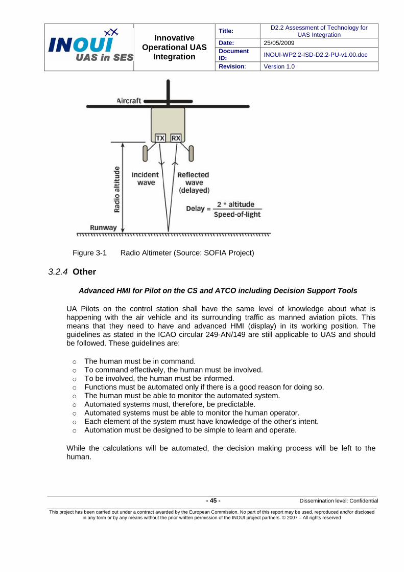
Title: D2.2 Assessment of Technology for UAS Integration
Date: 25/05/2009 Document ID: INOUI-WP2.2-ISD-D2.2-PU-v1.00.doc
Innovative Operational UAS
Integration Revision: Version 1.0
- 45 - Dissemination level: Confidential
This project has been carried out under a contract awarded by the European Commission. No part of this report may be used, reproduced and/or disclosed in any form or by any means without the prior written permission of the INOUI project partners. © 2007 – All rights reserved
Figure 3-1 Radio Altimeter (Source: SOFIA Project)
3.2.4 Other
Advanced HMI for Pilot on the CS and ATCO including Decision Support Tools
UA Pilots on the control station shall have the same level of knowledge about what is happening with the air vehicle and its surrounding traffic as manned aviation pilots. This means that they need to have and advanced HMI (display) in its working position. The guidelines as stated in the ICAO circular 249-AN/149 are still applicable to UAS and should be followed. These guidelines are:
o The human must be in command. o To command effectively, the human must be involved. o To be involved, the human must be informed. o Functions must be automated only if there is a good reason for doing so. o The human must be able to monitor the automated system. o Automated systems must, therefore, be predictable. o Automated systems must be able to monitor the human operator. o Each element of the system must have knowledge of the other’s intent. o Automation must be designed to be simple to learn and operate.
While the calculations will be automated, the decision making process will be left to the human.

Title: D2.2 Assessment of Technology for UAS Integration
Date: 25/05/2009 Document ID: INOUI-WP2.2-ISD-D2.2-PU-v1.00.doc
Innovative Operational UAS
Integration Revision: Version 1.0
- 46 - Dissemination level: Confidential
This project has been carried out under a contract awarded by the European Commission. No part of this report may be used, reproduced and/or disclosed in any form or by any means without the prior written permission of the INOUI project partners. © 2007 – All rights reserved
Conflict detection and conflict resolution advisories will be presented to the UA Pilot in a way that they become aware of what the system is doing and which information comes at which time into play, so that the UA Pilot can react suitably also in case of a system failure.
ATCO working position shall be also improved with new and advanced HMI (Human Machine Interface). This new advanced HMI shall include the foreseen systems that will allow the ATCO to have a better view of traffic situation and to assist him/her in detecting potential conflicts and resolving the conflicts timely. Some of these technologies are MTCA (Mid-Term Conflict Alert), STCA (Short Term Conflict Alert), What-if Probe, etc.
3.3 Cargo Flight Applications
According to the concept defined in INOUI D1.3, for Cargo Flight Applications, a set of technologies is required in order to enable the integration of UAS cargo flight applications. These technologies are common to the surveillance / observation technologies defined in section 3.2 above.
UAS cargo applications are unique to other missions in the sense of cargo handling activities. However, and for the scope of this section, the technologies required are common to the ones under section 3.2. Further issues to be considered when looking at cargo applications are airport compatibility. It is essential that the cargo vehicle is compatible with its operational airport (field length, runway loading, space occupied while loading and unloading, and compatibility with other cargo applications, facilitation of cargo handling and distribution and environmental considerations on the airport and surroundings). These issues are studied under INOUI Airport concepts for UAS in WP 6.
3.4 Station Keeping Applications
As mentioned in INOUI “D1.3 Proposal for the integration of UAS into the civil Airspace” Station Keeping Applications can be carried out by using three types of UAS: fixed wing UAS, rotary wing UAS and lighter than air UAS. When using fixed wing or rotary wing UAS the necessary requirements and technologies stated in sections 3.2 and 3.3 are still applicable.
In section 2.4 is mentioned that the focus of this study is on fixed wing and rotary wing UAS, as most applications are currently performed by these kinds of UAS. Applications of lighter than air (LTA) UAV are less common and are expected to remain so in the future.
Therefore, although the operational requirements for LTA UAS will not be identical to those for fixed wing and rotary wing UAS (the requirements regarding weather conditions will for instance be stricter), the list of operational requirements identified in this report could serve as a starting point for those to be developed for LTA UAS.
An adapted operational concept for LTA UA has to be developed in the future.

Title: D2.2 Assessment of Technology for UAS Integration
Date: 25/05/2009 Document ID: INOUI-WP2.2-ISD-D2.2-PU-v1.00.doc
Innovative Operational UAS
Integration Revision: Version 1.0
- 47 - Dissemination level: Confidential
This project has been carried out under a contract awarded by the European Commission. No part of this report may be used, reproduced and/or disclosed in any form or by any means without the prior written permission of the INOUI project partners. © 2007 – All rights reserved
4 UAS Technology Gaps 4.1 Introduction
Based on the technology description needed to fulfil the technical and operational requirements for Civil UAS applications defined in INOUI “D1.3 Proposal for the Integration of UAS into the Civil Airspace” made in section 2.2 and 2.3 above in this document, a set of technologies has been assigned for each requirement. The technologies assigned are those that currently exist either for UAS or for manned aviation. Manned aviation technologies are susceptible of being adapted for their use in UAS within the framework established by SESAR, i.e. 2020+.
Most of the technologies already exist, therefore the integration of UAS into non-segregated airspace should be possible from a technological perspective by 2020+. However there are some gaps that need to be bridged in order to assure that the integration of UAS will be efficient and safe. These gaps have been identified and are described hereafter.
4.2 General
The existing technologies fulfilling operational and technical requirements which allow the integration of UAS into non-segregated airspace are identified in this section. The technologies described are related to civil UAS applications performed with a fixed wing UAS carrying out either Surveillance/Observation, Cargo Flight or Station Keeping applications. For those Surveillance/Observation and Cargo Flight applications carried out with other rotary wing UAS please see under sections 4.3.
As stated in section 2.4 above, no technological requirements for station keeping applications have been derived when they are carried out by using lighter than air UAS. The reason is that the number of applications that will use this type of UAS will be very small compared to fixed wing or rotary wing UAS. Therefore no gaps will be derived for this type of applications in the case of fixed wing UAS. When these applications are carried out with fixed wing or rotary wing UAS, the technologies and found gaps identified in this section and in section 4.3 below are still applicable.
In the following table the technologies and gaps are analysed for requirements generally applicable to UAS, irrespective of the type of mission. For a reference of the requirement ID please go to section 2.2 above in this document. The third column of the table shows whether a gap exists or not. The requirements and description of the technologies for bridging the gaps are outside of the scope of this deliverable and will be given in INOUI “D2.3 Conclusions and Recommendations on new Technological Developments”.
Table 4-1 UAS Technology Gaps - General
Requirement ID Does a technology for this requirement exist? (Yes/no) Which one?
Does any gap exist?
REQ-MAN-GEN-PTO-001
Brake Systems could be among others: brake-by-wire, hydraulic or even autonomous brake control.
No

Title: D2.2 Assessment of Technology for UAS Integration
Date: 25/05/2009 Document ID: INOUI-WP2.2-ISD-D2.2-PU-v1.00.doc
Innovative Operational UAS
Integration Revision: Version 1.0
- 48 - Dissemination level: Confidential
This project has been carried out under a contract awarded by the European Commission. No part of this report may be used, reproduced and/or disclosed in any form or by any means without the prior written permission of the INOUI project partners. © 2007 – All rights reserved
Requirement ID Does a technology for this requirement exist? (Yes/no) Which one?
Does any gap exist?
REQ-MAN-GEN-PTO-002
Brake systems and chocks No
REQ-MAN-GEN-PTO-003
Pan European network service (PENS IP) is a ground network for VoIP ground telephony and datalink. The ground network interconnects the Air-Ground ATN routers and the ANSP ATN systems, releasing very high frequency spectrum for datalink use. The 802.16 standard covering the C band (4 - 8GHz frequencies), is a WIFI area network technology used also in airports that will provide a broadband access.
No
REQ-MAN-GEN-PTO-004
There are frequency selectors on the control station which allow to maintain communications in different frequencies
No
REQ-MAN-GEN-PTO-005
Every electronic system has always means to be started up. For security reasons, a user registration application with a password will allow to start up the system in a secure way
No
REQ-MAN-GEN-PTO-006
Ground Power Units as those existing in manned aviation, properly adapted to meet UAS requirements.
No
REQ-MAN-GEN-PTO-007
Specific software agent can synchronize the UA and CS starting up.
No
REQ-MAN-GEN-PTO-008
There are systems monitoring the state of critical systems onboard, during all phases of the flight and even capable to make predictions in a short and medium term regarding potential risks. These systems allow also to perform a Power Up Built inTest
No
REQ-MAN-GEN-PTO-009
ACARS (aircraft communication addressing and reporting system) or AOC (airlines operational communications), allow the UA pilot to create the flight plan on board the CS. Then it can be transmitted to the UA via datalink.
No
REQ-MAN-GEN-PTO-010
VoIP (Voice over Internet Protocol) and Controller-pilot data link communications (CPDLC) are application that allow for the direct exchange of IP voice and text-based messages between a controller and a pilot.
No
REQ-MAN-GEN-PTO-011
Push back hooks on the UA and push back vehicles on the aerodrome apron as those existing today for manned aviation.
No
REQ-MAN-GEN-PTO-012
Electronic flight bags (EFB) with wireless transmitter, are being developed to present an electronic map of the aerodrome surface in a exocentric perspective on a remote taxi-guidance display (TD) in order to provide the possibility to combine a high position error resolution with a large synthetic visible range.
No
REA-MAN-GEN-PTO-013
Direct telecommand (RLOS) through data link technologies over onboard flight control computer, may allow the pilot to perform turns in an appropriate way.
No

Title: D2.2 Assessment of Technology for UAS Integration
Date: 25/05/2009 Document ID: INOUI-WP2.2-ISD-D2.2-PU-v1.00.doc
Innovative Operational UAS
Integration Revision: Version 1.0
- 49 - Dissemination level: Confidential
This project has been carried out under a contract awarded by the European Commission. No part of this report may be used, reproduced and/or disclosed in any form or by any means without the prior written permission of the INOUI project partners. © 2007 – All rights reserved
Requirement ID Does a technology for this requirement exist? (Yes/no) Which one?
Does any gap exist?
REQ-MAN-GEN-PTO-014
VoIP and Controller-pilot data link communications (CPDLC) are application that allow for the direct exchange of IP voice and text-based messages between a controller and a pilot.
A direct datalink between ATC and the UA does not yet exist, enabling the UA to react directly to ATC instructions.
Sense and Avoid Technology for direct detection and sensing of conflicts on the aerodrome surface does not yet exist. Ground ASAS (Airborne Separation Assistance System) applications could be a potential solution in the future.
Yes
REQ-MAN-GEN-PTO-015
Electronic flight bags (EFB) with wireless transmitter allowing the UA to perform automatically taxiing procedures transmitting all the instructions to the Flight Management System.
VoIP and Controller-pilot data link communications (CPDLC) are applications that allow for the direct exchange of IP voice and text-based messages between a controller and a pilot.
No sense and avoid resolution in exists on taxi procedures yet
Yes
REQ-MAN-GEN-TO-016
Direct telecommand (RLOS) through data link technologies. No
REQ-MAN-GEN-TO-017
VoIP and Controller-pilot data link communications (CPDLC) are applications that allow for the direct exchange of IP voice and text-based messages between a controller and a pilot.
No
REQ-MAN-GEN-TO-018
Laser pointers through all the runway axis can align the UA to its direction. They can be integrated on the Electronic Flight Bags system. Gyroscopes as those used in manned aviation might allow to perform alignment with the runway.
No
REQ-MAN-GEN-TO-019
Direct telecommand (RLOS). No
REQ-MAN-GEN-TO-020
Direct telecommand (RLOS). No
REQ-MAN-GEN-TO-021
Direct telecommand (RLOS). No
REQ-GEN-MAN-TO-022
Automatic dependent surveillance-broadcast (ADS-B) aircraft will broadcast their GNSS positions once per second. Currently ADS-B technologies are fully developed. However, the regulatory framework for its implementation is not yet set. “ADS-B out” is already used on many aircraft whereas “ABS-B in” is still rare.
Yes
REQ-MAN-GEN-CLB-010
An FMS with VNAV (Vertical Navigation) capability already exists. A C2 link and user interface will allow direct telecommand from the CS and for monitoring the climb in case of need reaction of the UA pilot.
An airspeed probe and an Actuator Sensor Interface (Traditional “Auto-pilot” functions for airspeed, vertical speed, altitude, AoA), might help the UA pilot to monitor the climb phase.
No

Title: D2.2 Assessment of Technology for UAS Integration
Date: 25/05/2009 Document ID: INOUI-WP2.2-ISD-D2.2-PU-v1.00.doc
Innovative Operational UAS
Integration Revision: Version 1.0
- 50 - Dissemination level: Confidential
This project has been carried out under a contract awarded by the European Commission. No part of this report may be used, reproduced and/or disclosed in any form or by any means without the prior written permission of the INOUI project partners. © 2007 – All rights reserved
Requirement ID Does a technology for this requirement exist? (Yes/no) Which one?
Does any gap exist?
REQ-MAN-GEN-CLB-020
AoA control, (minimum solution as traditional AoA probe based stall warning or estimator), C2 (Command and Control) link, user interface with Check lists.
No
REQ-MAN-GEN-CLB-030
Vertical speed control (FMS with VNAV capability), C2 link and user interface.
No
REQ-MAN-GEN-CLB-040
If not equipped with an FMS including auto-throttle function, then adequate engine control with real time feed back and suitable sensing for critical parameters.
C2 link and user interface, according the system’s warning philosophy, indication of limits for operations (operating envelope protection), will allow to display every parameter on the CS.
No
REQ-MAN-GEN-CLB-050
If not equipped with an FMS including auto-pitch function, then adequate pitch control with real time feed back of blade angles and suitable sensing for critical parameters.
C2 link and user interface, according the system’s warning philosophy, indication of limits for operations (operating envelope protection), will allow to display every parameter on the CS.
No
REQ-MAN-GEN-CLB-060
Altimeter(s) according “minimum equipment Regulations” (depending on the system design) and a FMS with necessary precision for altitude control.
C2 link and user interface, according the system’s warning philosophy, indication of limits for operations (operating envelope protection), will allow to display every parameter on the CS.
No
REQ-MAN-GEN-CLB-070
FMS, navigation system, altimeter, air speed and heading information, together with a C2 link and user interface will allow to the UA pilot to have information ready to be reported when necessary.
VoIP and Controller-pilot data link communications (CPDLC) are applications that allow for the direct exchange of IP voice and text-based messages between a controller and a pilot.
No
REQ-MAN-GEN-CLB-080
See REQ-MAN-GEN-CLB-070 No
REQ-MAN-GEN-CLB-090
FMS with system related navigation system, “proceed on heading” or “proceed on track” capability.
No
REQ-MAN-GEN-CLB-100
Remotely controlled radio(s) and transponder(s).
C2 link and user interface will allow to the UA pilot to have information ready to be reported when necessary together with VoIP and CPDLC applications.
No

Title: D2.2 Assessment of Technology for UAS Integration
Date: 25/05/2009 Document ID: INOUI-WP2.2-ISD-D2.2-PU-v1.00.doc
Innovative Operational UAS
Integration Revision: Version 1.0
- 51 - Dissemination level: Confidential
This project has been carried out under a contract awarded by the European Commission. No part of this report may be used, reproduced and/or disclosed in any form or by any means without the prior written permission of the INOUI project partners. © 2007 – All rights reserved
Requirement ID Does a technology for this requirement exist? (Yes/no) Which one?
Does any gap exist?
REQ-MAN-GEN-CLB-110
If not equipped with “Auto gear function” embedded in the FMS a C2 link with user interface it is recommended in order to fulfill with the requirement, thus a capability to manually override the automatic functions may be needed.
Landing gear status indication, airspeed indication and Check lists should be incorporated.
No
REQ-MAN-GEN-CLB-120
If not equipped with “Auto flap function” embedded in the FMS a C2 link with user interface indicating flaps status. Airspeed indication and Check lists. See also: REQ-MAN-GEN-CLB-010 and REQ-MAN-GEN-CLB-020
No
REQ-MAN-GEN-CLB-130
See also: REQ-MAN-GEN-CLB-010 to REQ-MAN-GEN-CLB-050. No
REQ-MAN-GEN-CLB-140
See also: REQ-MAN-GEN-CLB-040 No
REQ-MAN-GEN-CLB-150
Altitude compensation for ASI (TAS function and display). A C2 link and user interface may be useful for the UA pilot on the CS.
No
REQ-MAN-GEN-CLB-160
Flight rule based assistance system using semi circular flight altitudes for planning, together with a C2 link and user interface.
However a technological means to avoid collisions such as Sense and Avoid are not currently possible
Yes
REQ-MAN-GEN-ERT-010
See : REQ-MAN-GEN-CLB-060 No
REQ-MAN-GEN-ERT-020
See: REQ-MAN-GEN-CLB-030 No
REQ-MAN-GEN-ERT-030
See: REQ-MAN-GEN-CLB-040 and REQ-MAN-GEN-CLB-050 No
REQ-MAN-GEN-ERT-040
See: REQ-MAN-GEN-CLB-040 No
REQ-MAN-GEN-ERT-050
See: REQ-MAN-GEN-CLB-010 to REQ-MAN-GEN-CLB-060 No
REQ-MAN-GEN-ERT-060
See: REQ-MAN-GEN-CLB-070 No
REQ-MAN-GEN-ERT-070
See: REQ-MAN-GEN-CLB-070 and REQ-MAN-GEN-CLB-090 No
REQ-MAN-GEN-ERT-080
See: REQ-MAN-GEN-CLB-100 No
REQ-MAN-GEN-ERT-090
See: REQ-MAN-GEN-CLB-160 Yes
REQ-MAN-GEN-ERT-095
Position lights and Anti-Collision Lighting (ACL) as those used in manned aviation properly adapted.
No

Title: D2.2 Assessment of Technology for UAS Integration
Date: 25/05/2009 Document ID: INOUI-WP2.2-ISD-D2.2-PU-v1.00.doc
Innovative Operational UAS
Integration Revision: Version 1.0
- 52 - Dissemination level: Confidential
This project has been carried out under a contract awarded by the European Commission. No part of this report may be used, reproduced and/or disclosed in any form or by any means without the prior written permission of the INOUI project partners. © 2007 – All rights reserved
Requirement ID Does a technology for this requirement exist? (Yes/no) Which one?
Does any gap exist?
REQ-MAN-GEN-ERT-100
On board cloud formation detections system or weather radar. Also optical systems may become useful if there are satellite communications good enough. Thus C3 (Communication, Command and Control) link to bring down visual information together with a user interface and the capability to change the current flight conduction if needed by the UA pilot from the CS.
VoIP and CPDLC to provide/receive information to/from ATC when needed
No
REQ-MAN-GEN-ERT-110
Dynamic flight management including dynamic fuel management together with C2 link and user interface in case of changes to the flight plan could allow to cope with changes in speed. This requirement leads to the necessity of the capability to proceed to alternate airfields which might be programmed in the FMS according to the flight plan.
VoIP and CPDLC will allow to transmit any change to ATC and vice versa
No
REQ-MAN-GEN-DSC-010
See also: REQ-MAN-GEN-CLB-010 No
REQ-MAN-GEN-DSC-020
See also: REQ-MAN-GEN-CLB-020 No
REQ-MAN-GEN-DSC-030
See also: REQ-MAN-GEN-CLB-030 No
REQ-MAN-GEN-DSC-040
See also: REQ-MAN-GEN-CLB-040 No
REQ-MAN-GEN-DSC-050
See also: REQ-MAN-GEN-CLB-050 No
REQ-MAN-GEN-DSC-060
See also: REQ-MAN-GEN-CLB-060 No
REQ-MAN-GEN-DSC-070
See also: REQ-MAN-GEN-CLB-070 No
REQ-MAN-GEN-DSC-080
See also: REQ-MAN-GEN-CLB-080 No
REQ-MAN-GEN-DSC-090
See also: REQ-MAN-GEN-CLB-090 No
REQ-MAN-GEN-DSC-100
See also: REQ-MAN-GEN-CLB-100 No
REQ-MAN-GEN-CLB-110
See also: REQ-MAN-GEN-CLB-110 No
REQ-MAN-GEN-DSC-120
See also: REQ-MAN-GEN-CLB-120 No
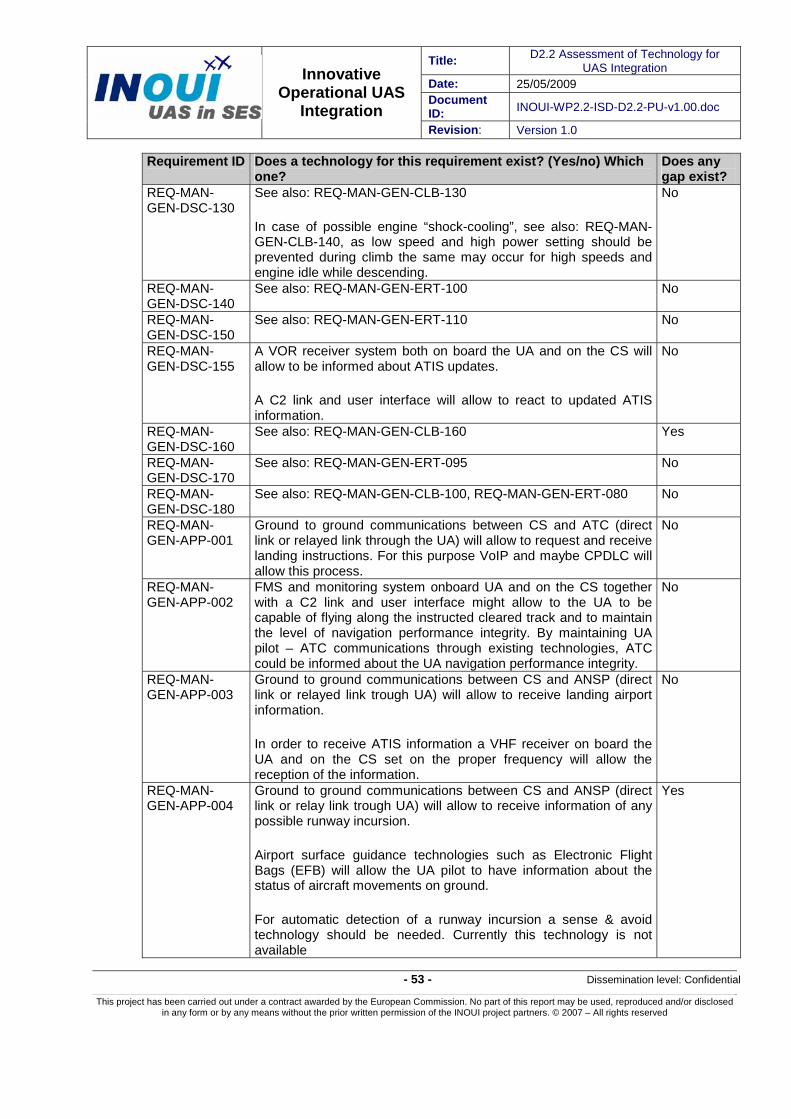
Title: D2.2 Assessment of Technology for UAS Integration
Date: 25/05/2009 Document ID: INOUI-WP2.2-ISD-D2.2-PU-v1.00.doc
Innovative Operational UAS
Integration Revision: Version 1.0
- 53 - Dissemination level: Confidential
This project has been carried out under a contract awarded by the European Commission. No part of this report may be used, reproduced and/or disclosed in any form or by any means without the prior written permission of the INOUI project partners. © 2007 – All rights reserved
Requirement ID Does a technology for this requirement exist? (Yes/no) Which one?
Does any gap exist?
REQ-MAN-GEN-DSC-130
See also: REQ-MAN-GEN-CLB-130
In case of possible engine “shock-cooling”, see also: REQ-MAN-GEN-CLB-140, as low speed and high power setting should be prevented during climb the same may occur for high speeds and engine idle while descending.
No
REQ-MAN-GEN-DSC-140
See also: REQ-MAN-GEN-ERT-100 No
REQ-MAN-GEN-DSC-150
See also: REQ-MAN-GEN-ERT-110 No
REQ-MAN-GEN-DSC-155
A VOR receiver system both on board the UA and on the CS will allow to be informed about ATIS updates.
A C2 link and user interface will allow to react to updated ATIS information.
No
REQ-MAN-GEN-DSC-160
See also: REQ-MAN-GEN-CLB-160 Yes
REQ-MAN-GEN-DSC-170
See also: REQ-MAN-GEN-ERT-095 No
REQ-MAN-GEN-DSC-180
See also: REQ-MAN-GEN-CLB-100, REQ-MAN-GEN-ERT-080 No
REQ-MAN-GEN-APP-001
Ground to ground communications between CS and ATC (direct link or relayed link through the UA) will allow to request and receive landing instructions. For this purpose VoIP and maybe CPDLC will allow this process.
No
REQ-MAN-GEN-APP-002
FMS and monitoring system onboard UA and on the CS together with a C2 link and user interface might allow to the UA to be capable of flying along the instructed cleared track and to maintain the level of navigation performance integrity. By maintaining UA pilot – ATC communications through existing technologies, ATC could be informed about the UA navigation performance integrity.
No
REQ-MAN-GEN-APP-003
Ground to ground communications between CS and ANSP (direct link or relayed link trough UA) will allow to receive landing airport information.
In order to receive ATIS information a VHF receiver on board the UA and on the CS set on the proper frequency will allow the reception of the information.
No
REQ-MAN-GEN-APP-004
Ground to ground communications between CS and ANSP (direct link or relay link trough UA) will allow to receive information of any possible runway incursion.
Airport surface guidance technologies such as Electronic Flight Bags (EFB) will allow the UA pilot to have information about the status of aircraft movements on ground.
For automatic detection of a runway incursion a sense & avoid technology should be needed. Currently this technology is not available
Yes
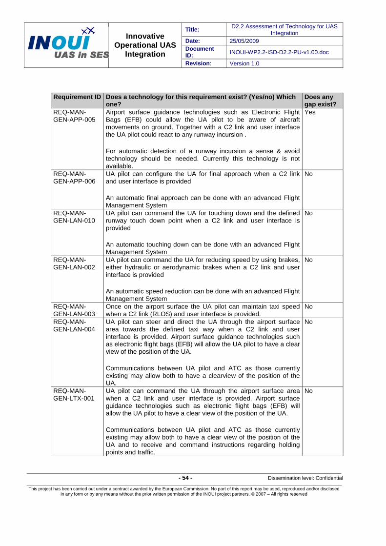
Title: D2.2 Assessment of Technology for UAS Integration
Date: 25/05/2009 Document ID: INOUI-WP2.2-ISD-D2.2-PU-v1.00.doc
Innovative Operational UAS
Integration Revision: Version 1.0
- 54 - Dissemination level: Confidential
This project has been carried out under a contract awarded by the European Commission. No part of this report may be used, reproduced and/or disclosed in any form or by any means without the prior written permission of the INOUI project partners. © 2007 – All rights reserved
Requirement ID Does a technology for this requirement exist? (Yes/no) Which one?
Does any gap exist?
REQ-MAN-GEN-APP-005
Airport surface guidance technologies such as Electronic Flight Bags (EFB) could allow the UA pilot to be aware of aircraft movements on ground. Together with a C2 link and user interface the UA pilot could react to any runway incursion .
For automatic detection of a runway incursion a sense & avoid technology should be needed. Currently this technology is not available.
Yes
REQ-MAN-GEN-APP-006
UA pilot can configure the UA for final approach when a C2 link and user interface is provided
An automatic final approach can be done with an advanced Flight Management System
No
REQ-MAN-GEN-LAN-010
UA pilot can command the UA for touching down and the defined runway touch down point when a C2 link and user interface is provided
An automatic touching down can be done with an advanced Flight Management System
No
REQ-MAN-GEN-LAN-002
UA pilot can command the UA for reducing speed by using brakes, either hydraulic or aerodynamic brakes when a C2 link and user interface is provided
An automatic speed reduction can be done with an advanced Flight Management System
No
REQ-MAN-GEN-LAN-003
Once on the airport surface the UA pilot can maintain taxi speed when a C2 link (RLOS) and user interface is provided.
No
REQ-MAN-GEN-LAN-004
UA pilot can steer and direct the UA through the airport surface area towards the defined taxi way when a C2 link and user interface is provided. Airport surface guidance technologies such as electronic flight bags (EFB) will allow the UA pilot to have a clear view of the position of the UA.
Communications between UA pilot and ATC as those currently existing may allow both to have a clearview of the position of the UA.
No
REQ-MAN-GEN-LTX-001
UA pilot can command the UA through the airport surface area when a C2 link and user interface is provided. Airport surface guidance technologies such as electronic flight bags (EFB) will allow the UA pilot to have a clear view of the position of the UA.
Communications between UA pilot and ATC as those currently existing may allow both to have a clear view of the position of the UA and to receive and command instructions regarding holding points and traffic.
No

Title: D2.2 Assessment of Technology for UAS Integration
Date: 25/05/2009 Document ID: INOUI-WP2.2-ISD-D2.2-PU-v1.00.doc
Innovative Operational UAS
Integration Revision: Version 1.0
- 55 - Dissemination level: Confidential
This project has been carried out under a contract awarded by the European Commission. No part of this report may be used, reproduced and/or disclosed in any form or by any means without the prior written permission of the INOUI project partners. © 2007 – All rights reserved
Requirement ID Does a technology for this requirement exist? (Yes/no) Which one?
Does any gap exist?
REQ-MAN-GEN-LTX-002
UA pilot can command the UA through the airport surface area performing a follow me procedure when a C2 link and user interface is provided. Airport surface guidance technologies such as electronic flight bags (EFB) will allow the UA pilot to have a clear view of the position of the UA.
Communications between UA pilot and ATC as those currently existing may allow both to have a clear view of the position of the UA.
No
REQ-MAN-GEN-LTX-003
UA pilot can command the UA through the airport surface area in order to complete the follow me procedure and to stop at the parking position assigned by ATC when a C2 link and user interface is provided. Airport surface guidance technologies such as electronic flight bags (EFB) will allow the UA pilot to have a clear view of the position of the UA.
Communications between UA pilot and ATC as those currently existing may allow both to have a clear view of the position of the UA.
No
REQ-MAN-GEN-LTX-004
UA pilot can command the UA to stop at the parking position assigned by ATC when a C2 link and user interface is provided. Airport surface guidance technologies such as electronic flight bags (EFB) will allow the UA pilot to have an accurate view of the position of the UA.
No
REQ-MAN-GEN-LTX-006
Every electronic system has always means to be powered down. No
REQ-MAN-GEN-LTX-007
Monitoring systems onboard UA as those used in manned aviation can check UA systems status and report to it the UA pilot on the CS. For any structural damage UAS crew can do it visually.
No
4.3 Surveillance/Observation and Cargo Flight Applications Particularities
In the following table the technologies and gaps are analysed for requirements generally applicable to rotary wing UAS, carrying out surveillance/observation or cargo flight applications. For a reference of the requirement ID please go to section 2.3 above in this document. The third column of the table shows whether a gap exists or not.
Table 4-2 UAS Technology Gaps – Surveillance/Observation and Cargo Flight Applications
Requirement ID
Does a technology for this requirement exist? (Yes/no) Which one?
Does any gap exist ? (yes/no)

Title: D2.2 Assessment of Technology for UAS Integration
Date: 25/05/2009 Document ID: INOUI-WP2.2-ISD-D2.2-PU-v1.00.doc
Innovative Operational UAS
Integration Revision: Version 1.0
- 56 - Dissemination level: Confidential
This project has been carried out under a contract awarded by the European Commission. No part of this report may be used, reproduced and/or disclosed in any form or by any means without the prior written permission of the INOUI project partners. © 2007 – All rights reserved
Requirement ID
Does a technology for this requirement exist? (Yes/no) Which one?
Does any gap exist ? (yes/no)
REQ-MAN-RWU-TAX-001
This requirement is likely to be met by means of appropriate ground handling commands instructed by the pilot from the Control Station via data link.
No
REQ-MAN-RWU-TAX-002
This requirement is likely to be met by means of appropriate ground handling commands instructed by the pilot from the Control Station via data link.
No
REQ-MAN-RWU-TAX-003
This requirement is likely to be met by means of appropriate ground handling commands instructed by the pilot from the Control Station via data link.
No
REQ-MAN-RWU-TAX-004
This requirement is likely to be met by means of appropriate ground handling commands instructed by the pilot from the Control Station via data link.
No
REQ-MAN-RWU-TO-005
This requirement is likely to be met by means of appropriate navigation and guidance commands instructed by the pilot from the Control Station via data link.
No
REQ-MAN-RWU-TO-006
This requirement is likely to be met by means of appropriate navigation and guidance commands instructed by the pilot from the Control Station via data link.
No
REQ-MAN-RWU-TO-007
This requirement is likely to be met by means of appropriate navigation and guidance commands instructed by the pilot from the Control Station via data link.
No
REQ-MAN-RWU-TO-008
This requirement is likely to be met by means of appropriate navigation and guidance commands instructed by the pilot from the Control Station via data link.
No
REQ-MAN-RWU-TO-009
This requirement is likely to be met by means of appropriate navigation and guidance commands instructed by the pilot from the Control Station via data link.
No
REQ-MAN-RWU-TO-010
This requirement is likely to be met by means of appropriate navigation and guidance commands instructed by the pilot from the Control Station via data link.
No
REQ-MAN-RWU-CLB-011
This requirement is likely to be met by means of appropriate navigation and guidance commands instructed by the pilot from the Control Station via data link.
No
REQ-MAN-RWU-CRF-012
This requirement is likely to be met by means of appropriate navigation and guidance commands instructed by the pilot from the Control Station via data link.
No
REQ-MAN-RWU-CRF-013
This requirement is likely to be met by means of appropriate navigation and guidance commands instructed by the pilot from the Control Station via data link.
No
REQ-MAN-RWU-CRF-014
This requirement is likely to be met by means of appropriate navigation and guidance commands instructed by the pilot from the Control Station via data link.
No
REQ-MAN-RWU-DSC-015
This requirement is likely to be met by means of appropriate navigation and guidance commands instructed by the pilot from the Control Station via data link.
No

Title: D2.2 Assessment of Technology for UAS Integration
Date: 25/05/2009 Document ID: INOUI-WP2.2-ISD-D2.2-PU-v1.00.doc
Innovative Operational UAS
Integration Revision: Version 1.0
- 57 - Dissemination level: Confidential
This project has been carried out under a contract awarded by the European Commission. No part of this report may be used, reproduced and/or disclosed in any form or by any means without the prior written permission of the INOUI project partners. © 2007 – All rights reserved
Requirement ID
Does a technology for this requirement exist? (Yes/no) Which one?
Does any gap exist ? (yes/no)
REQ-MAN-RWU-APP-016
This requirement is likely to be met by means of appropriate navigation and guidance commands instructed by the pilot from the Control Station via data link.
No
REQ-MAN-RWU-APP-017
This requirement is likely to be met by means of appropriate navigation and guidance commands instructed by the pilot from the Control Station via data link.
No
REQ-MAN-RWU-APP-018
This requirement is likely to be met by means of appropriate navigation and guidance commands instructed by the pilot from the Control Station via data link.
No
REQ-MAN-RWU-APP-019
This requirement is likely to be met by means of appropriate navigation and guidance commands instructed by the pilot from the Control Station via data link.
No

Title: D2.2 Assessment of Technology for UAS Integration
Date: 25/05/2009 Document ID: INOUI-WP2.2-ISD-D2.2-PU-v1.00.doc
Innovative Operational UAS
Integration Revision: Version 1.0
- 58 - Dissemination level: Confidential
This project has been carried out under a contract awarded by the European Commission. No part of this report may be used, reproduced and/or disclosed in any form or by any means without the prior written permission of the INOUI project partners. © 2007 – All rights reserved
5 ATM Technology Gaps 5.1 General
UAS operations are expected to cover a wide variety mission profiles. The most likely applications are identified for surveillance and observation missions, station keeping, e.g. for communication relays, and cargo operations.
The flight profiles of these missions are different from each other but generally they consist of take-off, not necessarily from a conventional runway, a climb and transit to a “target area”, a change in altitude from high to low to medium, a loitering requirement and possibly a return to base or onward transit to another destination. Recovery could utilise a runway or some unconventional landing system.
With the exception of transit flights, it is envisaged that UAS would be operated very rarely in the conventional point-to-point manner for which ATM infrastructure and its associated airspace has been designed to support. Therefore attention must be paid whether current and planned future ATM system components enable conducting these types of mission.
Given the complexity of the ATM environment with its vast number of systems, components and procedures that could be affected by the integration of UAS operations, there is a need to avoid or minimise any such changes. Any subsequent changes to existing systems, components and procedures will be costly, take time to implement and validate, and could have significant impact on ANSPs and the ATM Community.
Given the framework of SESAR and the ongoing initiatives to create a future European ATM system, it is rather unlikely that the different partners in the ATM environment are willing to initiate further R&D activities or invest in additional technologies, only to enable a new airspace user, yet little in numbers, the participation.
Therefore, it is desirable that UAS operations should take place without the need for special provisions such as additional infrastructure, further investment and new procedures.
5.2 Surveillance/Observation Applications
In section 3.1 the technology needs to enable the integration of UAS Surveillance/Observation applications have been described. An assessment of the capabilities of those technologies is shown hereafter in order to assess whether a technology gap exists or not.

Title: D2.2 Assessment of Technology for UAS Integration
Date: 25/05/2009 Document ID: INOUI-WP2.2-ISD-D2.2-PU-v1.00.doc
Innovative Operational UAS
Integration Revision: Version 1.0
- 59 - Dissemination level: Confidential
This project has been carried out under a contract awarded by the European Commission. No part of this report may be used, reproduced and/or disclosed in any form or by any means without the prior written permission of the INOUI project partners. © 2007 – All rights reserved
5.2.1 Communications
System Wide Information Management – SWIM
The proposed high level architecture for SWIM is based on the recommendations presented in SWIM-SUIT project.
Figure 5-1 SWIM Layered Architecture (Source: ATLANTIDA Project)
According to the information domains, the proposed layered architecture has two main groups of layers. The SWIM Infrastructure coloured in orange, which represents a common SWIM IT infrastructure, consisting in both turn-key solutions and toolkit/frameworks, on top of which the SWIM ATM functionality is built and the SWIM ATM functionality itself that corresponds to the blue layers, and represents the domain-specific functionality.
The aforementioned layers are themselves subdivided in two smaller layers splitting the whole system in four well defined logical layers.
- SWIM Physical Network layer represents the physical network which is the base to build other upper layers of the SWIM system. This layer corresponds to the Telecommunication Infrastructure that replaces the functionality currently provided by several owned and leased transport systems. This network provides the needed communications infrastructure to build the immediate upper layer: SWIM Technical Services (core).
- SWIM Technical Services (core) represents the core of technical services that SWIM will provide to all connected systems. The use of core capabilities depends on the business needs for each service. Every service will not necessarily require every core capability or the same capability level. Consequently, the core will be subject to incremental implementation as requirements and programming priorities dictate.
- SWIM ATM Data Access Services embodies the SWIM virtual information pool. It provides access to the SWIM ATM Data model through previously defined services. Following the recommendations suggested in SWIM-SUIT project, the data access services will typically be defined according to the specific domain of information involved in such service (e.g. Access to Trajectory Data, Access to Meteo Data).

Title: D2.2 Assessment of Technology for UAS Integration
Date: 25/05/2009 Document ID: INOUI-WP2.2-ISD-D2.2-PU-v1.00.doc
Innovative Operational UAS
Integration Revision: Version 1.0
- 60 - Dissemination level: Confidential
This project has been carried out under a contract awarded by the European Commission. No part of this report may be used, reproduced and/or disclosed in any form or by any means without the prior written permission of the INOUI project partners. © 2007 – All rights reserved
- SWIM Advanced ATM Services contains services that provide access to advance ATM functionality beyond that of the virtual information pool. This layer containsapplications and services that will support, among others, the CDM (Collaborative Decision Making) processes.
In the future context of SESAR there will be a SWIM infrastructure that will allow UAS to be integrated into a SWIM environment, therefore in the timeframe 2020+ this technology is not considered a gap. However at the moment of development of this deliverable this technology is in its definition phase therefore there is a small risk that this technology will not be ready and implemented in the mentioned timeframe.
5.2.2 Navigation
Advanced FMS
The Flight Management System is a powerful tool that supports the pilot in the management of the flight, currently permitting the following functions:
• to initialise flight plans (Active Flight Plan, Secondary Flight plans) and to modify them, • to enter or input data linked to the performances of the flight (weights, fuel, speeds,
winds …) • to compute optimised trajectory and vertical profile, respecting standard rules and
specific flight constraints, • to guide autonomously the Auto-Pilot along the computed trajectory and profile, • to perform predictions (speed, altitude, time, fuel) for the flight plan still to fly, • to provide output data to the cockpit display devices for trajectory, profile and guidance
mode display, • to help for A/C position management or computation • to automatically tune radio navaids, • to interface for communication with ground by AOC (Airline Operator Center
communications) or ATC (ATM communications.), • to display and interact with its FMS internal data through HMI (Human Machine
Interface), • to manage the printing of the flight plan
In order to make performance computations and trajectory predictions, the FMS needs the following data as input:
• Zero Fuel Weight (ZFW) and Zero Fuel Centre of Gravity (ZFCG) • Block fuel • Airline cost index (CI) • Flight conditions (cruise flight level, temperature, wind).
With these data, the FMS computes the following outputs

Title: D2.2 Assessment of Technology for UAS Integration
Date: 25/05/2009 Document ID: INOUI-WP2.2-ISD-D2.2-PU-v1.00.doc
Innovative Operational UAS
Integration Revision: Version 1.0
- 61 - Dissemination level: Confidential
This project has been carried out under a contract awarded by the European Commission. No part of this report may be used, reproduced and/or disclosed in any form or by any means without the prior written permission of the INOUI project partners. © 2007 – All rights reserved
• Wind and temperature • Speed changes • Pseudo waypoint computation: top of climb (T/C), top of descent (T/D), Level off (LVL
OFF),… • For each waypoint or pseudo waypoint:
o Distance o Estimated Time of Arrival (ETA) o Speed o Altitude o Estimated Fuel On Board (EFOB) o Wind for each waypoint or pseudo waypoint.
• For primary and alternate destination:
o ETA o Distance to destination o EFOB at destination.
These predictions are continually updated depending on:
• Business trajectory information • Current winds and temperature • Current guidance modes
The FMS can also process trajectories uplinked from the ground, by ATC for ATM uplinks. FMS can also communicate its trajectory intent to the ground or to other A/C by data link and ADS-B or ADS-C (Automatic Dependent Surveillance-Contract).
An FMS often embeds a position computation function, to be used for guidance purpose. This position is computed by integration of ADIR (Aircraft Data Insertion Retrieval) positions, GPS (Global Positioning System) positions and Radio navaids computed positions.
Flight Management System is a technology being constantly improved. Current FMS have capabilities that will allow UAS to fly into the current non-segregated airspace. It is expected that by the 2020+ timeframe, FMS will have even more capabilities than today, however the developments of these systems are mainly focused on manned aircraft, especially for big airliners, but in recent times also for general aviation aircraft. Therefore it is recommended that in developments of advanced FMS, UAS industry should be involved leading to a fulfilment of Advanced FMS gaps with regard to UAS in 2020+ .
Flight Reconfiguration Function
The FRF (Flight Reconfiguration Function) has three possible solutions for carrying out the trajectory replanning:
Title: D2.2 Assessment of Technology for UAS Integration
Date: 25/05/2009 Document ID: INOUI-WP2.2-ISD-D2.2-PU-v1.00.doc
Innovative Operational UAS
Integration Revision: Version 1.0
- 62 - Dissemination level: Confidential
This project has been carried out under a contract awarded by the European Commission. No part of this report may be used, reproduced and/or disclosed in any form or by any means without the prior written permission of the INOUI project partners. © 2007 – All rights reserved
• Solution 1 – without negotiation: This is the pure autonomous solution. The FRF based on the inputs from the systems on board (ACAS, ASAS, GPWS, Weather Radar) evaluates the best trajectory to be flown and executes it. The trajectory is commanded by the FMS. In the future ATM environment defined by SESAR, once the FRF has developed the trajectory to be flown, it will send it to ground and therefore to other aircraft via SWIM in order to participate in the Collaborative Decision Making Process (CDM) in which all the airspace users will participate in order to meet their business trajectory.
• Solution 2 – with negotiation with ground: In this solution, ground ATC or even the UA pilot itself will propose a trajectory free of conflicts based on the inputs transmitted from the systems on-board the air vehicle and it will be negotiated by the FRF. Once ATC or UA Pilot has created the new trajectory free of conflicts, it is transmitted via data link to the UA and distributed via SWIM in order to participate in the CDM Process. When the trajectory is accepted by the FMS, it will command the trajectory and the FRF will monitor it.
• Solution 3 – Aircraft relay: This solution will rely on another aircraft or even another UA, flying in the surroundings of the UA, which can relay via air-air communications a trajectory free of conflicts. The FRF is in charge of managing the transmission and acceptance of the new trajectory and then the FMS will command it while the FRF monitors the flight.
Due to the fact that the FRF is a safety critical system, it is necessary to make possible that the FRF is not active unless it is needed to create a new trajectory. Therefore, the FRF has four modes of operation:
• START: This mode is active only when the UA is started up. Its function is to perform a Power Up Built in Test and to upload all the necessary information in the databases in case during the flight a new trajectory is needed.
• IDLE: If the original trajectory is being flown and a new trajectory is not necessary, this mode will be active, in order to maintain a safe flight.
• ARMED: Once a conflict has been detected, this mode is in charge of managing the creation or negotiation of the new trajectory for avoiding the conflict with the inputs from the systems on-board the UA and the information transmitted from ground (e.g. weather)
• ACTIVE: Once the FMS makes active the new trajectory, then the FRF is set in ACTIVE Mode in order to monitor the flight and to be ready for another trajectory creation or negotiation until the UA has landed. This mode is also in charge of establishing the proper configuration of the UA for landing and managing it.
The Flight Reconfiguration Function System is currently being studied in research projects, and it is expected that this technology could be available for the 2025+ timeframe. Therefore at the moment of implementation of the SESAR concept, there will be a gap regarding this system. It is important as well to adapt or to develop for UAS, systems such as GPWS or weather radar allowing the FRF to receive the necessary inputs for its operation

Title: D2.2 Assessment of Technology for UAS Integration
Date: 25/05/2009 Document ID: INOUI-WP2.2-ISD-D2.2-PU-v1.00.doc
Innovative Operational UAS
Integration Revision: Version 1.0
- 63 - Dissemination level: Confidential
This project has been carried out under a contract awarded by the European Commission. No part of this report may be used, reproduced and/or disclosed in any form or by any means without the prior written permission of the INOUI project partners. © 2007 – All rights reserved
5.2.3 Surveillance
Air-Ground and Air-Air Data Link Communications and Surveillance Broadcast
The need for adequate future communication capability and ensure the efficient use of European airspace was discussed at the ICAO Eleventh Air Navigation Conference and the EUROCONTROL directorate of Civil-Military ATM coordination. Conclusions agreed that the aeronautical mobile communication infrastructure has to evolve in order to accommodate new functions and to provide the adequate capacity and quality of services required to support evolving ATM requirements within the framework of the global ATM operational concept. Interaction between military technical enablers and civil systems supporting ATM are foreseen to play a vital role in facilitating the military requirements within SESAR Master Plan.
In order to achieve these goals several guidelines have been established including global interoperability, investigation of future technology alternatives and standardisation of aeronautical communication systems. Some studies have proposed a new system which assures interoperability between civil and military aviation, and proposes a new set of messages especially designed for ADS-B, following Link 16 rules. The software to manage these new messages would be embedded in the military equipment. The set of ADS-B messages guarantees separate operation of the ATC and non-ATC functions on the military equipment, greatly reducing the possibilities of mutual interference with military equipment. State aircraft equipped with normal MIDS (Multifunctional Information Distribution System) flying as GAT (General Air Traffic) would be fully interoperable with all other GAT flights equipped with the new system. It is unlikely that there would be interference between GAT flights equipped with the new system and OAT (Operational Air Traffic) flights equipped with full MIDS, as the systems would operate in different frequencies or nets.
Figure 5-2 depicts an overview of the jointly agreed to approach for the implementation and evolution of aeronautical mobile communications to support the emerging and anticipated needs of air traffic management in both Europe and the U.S.

Title: D2.2 Assessment of Technology for UAS Integration
Date: 25/05/2009 Document ID: INOUI-WP2.2-ISD-D2.2-PU-v1.00.doc
Innovative Operational UAS
Integration Revision: Version 1.0
- 64 - Dissemination level: Confidential
This project has been carried out under a contract awarded by the European Commission. No part of this report may be used, reproduced and/or disclosed in any form or by any means without the prior written permission of the INOUI project partners. © 2007 – All rights reserved
Figure 5-2 Agreed approach for implementation of Datalink Technologies (Source: EUROCONTROL)
In the near term, ATC operations (as well as AOC) will continue to use the allocated VHF (Very High Frequency) spectrum. European VHF band is still expected to become saturated necessitating use of additional systems to share the load.
Once digital data communications are established, and the operational paradigm changes to be based on digital data exchange as the prime means for safe and efficient ATC operations, it is expected that the need for data communications will grow.
In parallel, because of regional limitations within the VHF band, Europe will deploy the jointly developed terrestrial L-Band digital link technology (L-DACS) to support its users.
Organisations and agencies are requested to monitor the implementation of this technology in Europe and evaluate the use of L-band digital link technology. For example, during this term, the FAA (Federal Aviation Administration) will study the integration of Mode S ES and UAT capabilities for ATC data applications, as well as study, the potential for using the jointly defined L-band digital link. It is foreseen that since Europe will also require an alternative ADS-B link in this time frame, this internationally standardized L-band digital link will be studied as a potential candidate.

Title: D2.2 Assessment of Technology for UAS Integration
Date: 25/05/2009 Document ID: INOUI-WP2.2-ISD-D2.2-PU-v1.00.doc
Innovative Operational UAS
Integration Revision: Version 1.0
- 65 - Dissemination level: Confidential
This project has been carried out under a contract awarded by the European Commission. No part of this report may be used, reproduced and/or disclosed in any form or by any means without the prior written permission of the INOUI project partners. © 2007 – All rights reserved
As can be seen in figure 5-2, Datalink technology for air-ground communications, satellite communications and airport communications will be available in 2020 for manned aircraft. However there are three gaps for these technologies:
- Air-Air communications via datalink will be not available - This technology is not being developed for UAS. - Mid-space collisions between satellites and/or “space-waste” may result in
unpredictable link losses.
Therefore it is recommended to focus the development of this technology for UAS, and specific technical requirements for its use in unmanned aircraft need to be given.
Advanced Ground Surveillance Support
As mentioned in section 3.1.3 Advanced Ground Surveillance Support aim is to cope with possible limitations of the direct air-air communications. Technologies either already existing or foreseen are:
• TIS-B
Traffic Information Service – Broadcast (TIS-B) is a function of ADS-B and is a surveillance service that derives traffic information from one or more ground surveillance sources and broadcasts this information to ADS-B equipped aircraft or surface vehicles, with the intention of supporting ASAS applications. The users of TIS-B include airborne aircraft, aircraft operating on an airport surface, and a select set of airport surface vehicles.
The TIS-B system architecture is expected to include both regional control facilities and ground broadcast stations. TIS-B Control Facilities are where surveillance processing and report generation and distribution are performed for the TIS-B system, such that all targets are registered relative to each other and identified uniquely. TIS-B Control Facilities may be networked together to facilitate data exchange and coordination. Each TIS-B Control Facility may have one or more TIS-B Ground Stations affiliated with it. The Ground Stations may be at remote locations and each will contain, at a minimum, a transmitter for broadcasting the TIS-B messages. The TIS-B Control Facilities and Ground Stations may be part of other surveillance systems, and need not be separate physical entities. TIS-B services will be available where there is both adequate surveillance coverage from ground sensors and adequate Radio Frequency (RF) broadcast coverage from TIS-B Ground Stations. Where there is continuous surveillance and RF coverage, seamless TIS-B services can be provided.
The level of quality of traffic information provided by TIS-B is dependent on the number and type of ground sensors available as sources for TIS-B and the timeliness of the reported data. Each ASA application will require a minimum level of quality for the TIS-B targets in the airspace where aircraft are performing the application. There are two ways that an aircraft can determine whether TIS-B targets meet the required level.
Firstly, a TIS-B service may have an implied minimum level of quality for a defined volume of airspace, thus assuring that all targets for that service volume meet the requirements for

Title: D2.2 Assessment of Technology for UAS Integration
Date: 25/05/2009 Document ID: INOUI-WP2.2-ISD-D2.2-PU-v1.00.doc
Innovative Operational UAS
Integration Revision: Version 1.0
- 66 - Dissemination level: Confidential
This project has been carried out under a contract awarded by the European Commission. No part of this report may be used, reproduced and/or disclosed in any form or by any means without the prior written permission of the INOUI project partners. © 2007 – All rights reserved
participation. Secondly, individual TIS-B reports may contain a quality measure from which the receiving aircraft may determine if each report meets the application requirements.
In summary:
• TIS-B is the service of broadcasting traffic information to all equipped aircraft. The source of this traffic information is derived from ground-based air traffic surveillance sensors, typically radar; ground stations perform the gathering, compilation and broadcast transmission of this information.
• ATC uses the same data for surveillance as that sent to the pilots, who use it to obtain a visualisation of the traffic around them. This leads to an important harmonisation in this matter.
• The TIS-B service is becoming available in selected locations where there are both adequate surveillance coverage from ground sensors and adequate broadcast coverage from GBTs.
• The quality level of traffic information provided by TIS-B is dependent upon the number and type of ground sensors available as TIS-B sources and the timeliness of the reported data.
The following figure shows the principle of TIS-B:
Figure 5-3 Principle of TIS-B Operation (Source: SOFIA Project)
Conceptually, TIS-B makes use of ground-based surveillance equipment, typically secondary radar, too, to track the position of aircraft. “ADS-B like” messages for those aircraft are then generated and broadcast by a TIS-B ground station on the 1090 MHz frequency. It is envisaged that, in NG-ISS timescales, aircraft equipped with a 1090 MHz receiver will be able to receive and decode TIS-B messages for display on a CDTI or for other purposes. While 1090 MHz ADS-B receivers are now being developed, it is expected that these

Title: D2.2 Assessment of Technology for UAS Integration
Date: 25/05/2009 Document ID: INOUI-WP2.2-ISD-D2.2-PU-v1.00.doc
Innovative Operational UAS
Integration Revision: Version 1.0
- 67 - Dissemination level: Confidential
This project has been carried out under a contract awarded by the European Commission. No part of this report may be used, reproduced and/or disclosed in any form or by any means without the prior written permission of the INOUI project partners. © 2007 – All rights reserved
receivers will also be capable of receiving TIS-B messages. TIS-B allows any aircraft equipped with a conventional transponder to be made visible on a cockpit display in another aircraft. The important point, however, is that the tracked aircraft needs to be in radar coverage, while the receiving aircraft has to be within the broadcast region of the TIS-B ground station. The following graphic shows the TIS-B concept:
Figure 5-4 TIS-B Concept (Source: SOFIA Project)
In TIS-B, there are two different air-spaces:
o The SV (Service Volume) is the area where TIS-B can be received. It must be covered by the radar ground station and the TIS-B ground station. The purpose of a SV is to give the pilot the certainty that he can rely on the displayed surveillance data. Beyond the SV, the surveillance data are not complete since TIS-B is missing there. Therefore, aircraft without ADS-B will continue staying “invisible”. There are different types of SV, a ground-side and an on-board. The main difference is that data of ground vehicles are not transmitted into a ground-side SV. A SV is defined by the shape of a polygon and a minimum and maximum height.
o The TIV (Traffic Information Volume) is the area where the TIS-B is providing data. All objects outside this zone are not detected, i.e. their data are not forwarded.
Each TIS-B ground station shall be capable to provide four SVs, but each SV should be provided only by one TIS-B ground station. SVs may overlap. It is planned that in each aircraft several SVs might be displayed.
A TIS-B ground station transmits surveillance data at regular intervals. There are two different kinds of messages that are transmitted: management and target messages. A management message contains information about the settings of the TIS-B service and the definition of the SV. A target message may be addressed to different types within the SV: an aircraft on the ground, an aircraft in flight or a ground vehicle. Each transmission starts with a management message, followed by a target message for each type in the SV.

Title: D2.2 Assessment of Technology for UAS Integration
Date: 25/05/2009 Document ID: INOUI-WP2.2-ISD-D2.2-PU-v1.00.doc
Innovative Operational UAS
Integration Revision: Version 1.0
- 68 - Dissemination level: Confidential
This project has been carried out under a contract awarded by the European Commission. No part of this report may be used, reproduced and/or disclosed in any form or by any means without the prior written permission of the INOUI project partners. © 2007 – All rights reserved
Currently, two different TIS-B modes are taken into consideration:
o TIS-B transmitting a complete picture of current traffic situation, i.e. a “full surveillance picture”.
o TIS-B transmitting the data to aircraft, equipped with ADS-B, only in the following cases, i.e. a “gap filter”:
o The position information, transmitted by means of ADS-B, seem to be incorrect. o There is a gap in the ADS-B coverage. o The ADS-B update rate is insufficient.
Recently, the TIS-B MASPS (Minimum Aviation System Performance Standards) were issued as RTCA DO-286(A) developed by the RTCA SC 186 WG 4 [DO-286(A)].
• ATCO Support Tools
The processed information in the several technical systems which constitute ATM, especially surveillance and navigation data, can be used by human operator, particularly the ATCO. Certain tools can utilise these information and display it accordingly to ATCO in order to alert the ATCOs where there is (or could be a conflict) and to allow them to react before the conflict takes place and to contact the aircraft involved in the conflict in advance.
Some of these tools are:
- Short Term Conflict Alert – STCA - Medium Term Conflict Detection – MTCD - Monitoring Aids – MONA - What-if Probe - Conflict Resolution Assistance – CORA
For a detailed description of these ATCO Support Tools refer to INOUI “D2.1 Report on Technology Systems Solutions”
In principle SESAR does not foresee the need of TIS-B for aircraft operations because of the mandate of ADS-B ES 1090 out. However it is needed to consider whether this technology will be useful for its use on UAS or not.
Regarding ATCO support tools, they are currently being developed and most of them will be available for its implementation in the short term. Moreover, if the statement that UAS will be transparent to ATC is maintained, these tools will not need of adaptation for UAS.
ACAS
TCAS system identifies the location and tracks the progress of aircraft equipped with Mode C or S transponders and can detect and track as many as 35 to 40 intruders simultaneously

Title: D2.2 Assessment of Technology for UAS Integration
Date: 25/05/2009 Document ID: INOUI-WP2.2-ISD-D2.2-PU-v1.00.doc
Innovative Operational UAS
Integration Revision: Version 1.0
- 69 - Dissemination level: Confidential
This project has been carried out under a contract awarded by the European Commission. No part of this report may be used, reproduced and/or disclosed in any form or by any means without the prior written permission of the INOUI project partners. © 2007 – All rights reserved
within an approximate 40 nautical mile range. Each of these intruders is filed and prioritized by level of threat and displayed on the traffic display for pilot and co-pilot viewing.
TCAS II is capable of interrogating Mode A, Mode C and Mode S transponders and also advises the pilot to execute or to avoid a vertical manoeuvre that will maintain vertical separation from the intruder (Resolution Advisory – RA).
Currently the TCAS II must meet the Minimum Operational Performance Specifications (MOPS) software version 6.04A and such requirements are explained and contained in an RTCA document DO-185. This (MOPS) 6.04A software has also been revised and upgraded to the newest (MOPS) 7.0 documented in DO-185A, recently approved by the FAA and the ICAO implementing improvements in the performance of the collision systems, avoiding the nuisance traffic alerts when flying in the new Reduced Vertical Separations Minimums (RVSM), and meeting the new requirements for future operations in the very busy European airspace and in the rest of the world.
Physically, an ACAS system on an aircraft consists of a directional antenna that interrogates other traffic’s transponders. The antenna is connected ACAS interrogator/receiver enabling the aircraft to track other traffic in the vicinity. The ACAS logic processor determines threats and computes data to be displayed on the cockpit. Being ACAS a cooperative system, an omni-directional antenna is connected to a transponder and a responds in the same manner to other aircraft interrogations.
Based on the replies of each aircraft, TCAS assesses the situations with regards to possible threats. Tri-dimensional protection volumes enclose each aircraft, and violations of those areas trigger an alarm. The volumes are calculated according to aircraft altitude and the warnings are issued on a fixed time anticipation basis, dictated by the closure rate.

Title: D2.2 Assessment of Technology for UAS Integration
Date: 25/05/2009 Document ID: INOUI-WP2.2-ISD-D2.2-PU-v1.00.doc
Innovative Operational UAS
Integration Revision: Version 1.0
- 70 - Dissemination level: Confidential
This project has been carried out under a contract awarded by the European Commission. No part of this report may be used, reproduced and/or disclosed in any form or by any means without the prior written permission of the INOUI project partners. © 2007 – All rights reserved
Figure 5-5 TCAS levels of protection (Source: SOFIA Project)
From the equipment maturity point of view, TCAS actually stands for a family of applications that, and several equipment, have been made standard over the years after intensive study by the FAA, other countries’ Civil Aviation Authorities (CAAs) and aircraft industry. At the moment TCAS I and TCAS II coexist in the aeronautical panorama in some parts of the world. Note that TCAS I is not permitted to be used in some European airspace.
According to an ICAO mandate, ACAS (and thus TCAS II) has to be used by bigger aircraft above 5.7 t weight. Besides offering traffic advisories like TCAS I, it is capable of issuing resolution advisories (RA) for conflict avoidance in the vertical direction, helping pilot to establish a safe vertical separation in time to avoid the collisions. In case both aircraft have TCAS systems, TCAS II will compute coordinated Resolution Advisories. This can be a limitation for its use in UAS, due to most of them will be to small and not compliant with the weight decided by ICAO.
For the pilot, the traffic situation is available in aural and graphical form. In the case of UAS this aural and graphical signals should be presented to the pilot on the Control Station, while the results of the computations made by TCAS should be transmitted in a proper way to the on-board equipment in charge of dealing with conflict detection and resolution.

Title: D2.2 Assessment of Technology for UAS Integration
Date: 25/05/2009 Document ID: INOUI-WP2.2-ISD-D2.2-PU-v1.00.doc
Innovative Operational UAS
Integration Revision: Version 1.0
- 71 - Dissemination level: Confidential
This project has been carried out under a contract awarded by the European Commission. No part of this report may be used, reproduced and/or disclosed in any form or by any means without the prior written permission of the INOUI project partners. © 2007 – All rights reserved
TCAS is a last ditch conflict detection mechanism. That implies also short time avoidance actions to be taken. To ensure the pilot becomes aware of any TA and RA in due time, consistent aural messaging is used.
Some characteristics:
Tracking capability: 30 to 100 targets
Surveillance range: 30-40 NM typical
Closing rate: 600 to 1200 knots
TCAS being connected to automatic flight control systems imply slow manoeuvre resolution because the autopilot is designed for maximum passenger comfort, limiting the vertical accelerations, in the case of UAS where no passenger are on-board this limitation is not a problem.
TCAS just brings TAs (Traffic Advisory) and RAs (Resolution Advisory) to the attention of the pilots, and it is the ultimate responsibility of the UA Pilot to avoid any threatening traffic when an RA is issued (Note that pilots are not allowed to manoeuvre based solely on the Traffic Advisory due to its limited accuracy. However, there is a clear recommendation to follow an RA, even if a different ATC clearance has been given).
A possibility would be to feed the RA information into a Flight Reconfiguration Function (FRF) and to let the FRF fly the manoeuvre. It should however be noted that the responsibility would then be completely with the system.
TCAS II Version 7 is the current evolution for ACAS. Even though no major innovations were added, algorithms were improved in some essential areas from the version 6.04. Effort was put into bug correction and reduction of non-dangerous alerts. Changes are not very noticeable unless a very deep knowledge of the system operation and design is held. They however addressed and corrected a vast number of details that make the whole system quite safer and credible. Overall:
• Minimum detection ranges were increased; • Radar altitude is relied upon for ground aircraft distinguishing; • “fake” TAs on approaches to parallel runways reduced; • Vertical separation volumes were re-dimensioned above flight level 300 to cope with
reduced vertical separation minima (RVSM) separation; • RA coordination between both aircraft was improved; • RAs issued in no danger situations as aircraft climbing to high level corridors beneath
other aircraft are delayed; • Much improved multi-aircraft conflicts resolution; • RA order reversals can be issued depending of the evolution of the conflict; • Aural alerts and displays more adequate for human reaction; • The way to integrate ACAS with ADS-B has been paved, with the inclusion of capability
for ACAS to receive ADS-B mode-S traffic reports from other aircraft.

Title: D2.2 Assessment of Technology for UAS Integration
Date: 25/05/2009 Document ID: INOUI-WP2.2-ISD-D2.2-PU-v1.00.doc
Innovative Operational UAS
Integration Revision: Version 1.0
- 72 - Dissemination level: Confidential
This project has been carried out under a contract awarded by the European Commission. No part of this report may be used, reproduced and/or disclosed in any form or by any means without the prior written permission of the INOUI project partners. © 2007 – All rights reserved
TCAS and Non Cooperative Traffic
VFR flights in non controlled airspace can represent great danger to TCAS equipped UAS when crossing one of the areas in which non-cooperative traffic flies. In this kind of areas there is no transponder code attributed to each aircraft, they fly with VFR squawk code 7000 but in different transponder modes, and general aviation aircraft usually do not have TCAS equipment onboard. VFR traffic can fly with different transponder modes, and own ship TCAS will react differently depending on the situation.
UAS have the risk of getting in conflict with non-controlled general aviation flight aircraft operating under VFR when descending to the airport. VFR aircraft typically use a special SSR transponder code “7000” for Mode A, with or without altitude reporting (Mode C). Furthermore general aviation aircraft usually do not have TCAS equipment onboard. So they operate on with different transponder modes, and own ship TCAS will react differently depending on the situation:
• Intruder has SSR transponder set to OFF or STAND-BY: own-ship TCAS II cannot detect the intruder and therefore there is no alert at all.
• Intruder has SSR transponder set to ON, without altitude reporting: TCAS II will only generate Traffic Advisory (TA) to help the pilot achieve visual contact. However, the TA is unable to show whether the aircrafts are at the same altitude or not.
• Intruder has SSR transponder set to ALT: TCAS II can trigger TAs and Resolution Advisories (RAs). An RA, if followed, protects the VFR traffic as well as the traffic equipped with TCAS II from collision.
For maximum safety VFR traffic must squawk altitude.
Although, even if they are detected by the own ship TCAS, they will not get an indication of a conflict and the resolution manoeuvre has to be done by the own ship only.
ACAS technologies are in used in manned aviation since several years ago and their use is widespread across the world. However this equipment is designed for manned aviation only and the size and weight make not possible to be introduced in UAS except for big ones. It is recommended to develop ACAS equipment according to UAS specifications in order to fulfill the gap that currently exists.
Terrain Detection
Ground Proximity Warning Systems
The aim of Ground Proximity Warning System is to give visual and audible alert warning signals to pilots when aircraft’s proximity to terrain poses a potential threat to its safety.
Inputs to the system come from radio altimeter, mach meter, air data computer, glide path deviation, undercarriage position, flaps position and navigation system. The system operates

Title: D2.2 Assessment of Technology for UAS Integration
Date: 25/05/2009 Document ID: INOUI-WP2.2-ISD-D2.2-PU-v1.00.doc
Innovative Operational UAS
Integration Revision: Version 1.0
- 73 - Dissemination level: Confidential
This project has been carried out under a contract awarded by the European Commission. No part of this report may be used, reproduced and/or disclosed in any form or by any means without the prior written permission of the INOUI project partners. © 2007 – All rights reserved
between 50 feet and 2450 feet actual height above the surface and automatically selects the correct mode of operation. Outputs are sent to the master indicator, visual warnings and audio warnings.
Mode 1 – Excessive barometric descent rate
Mode 1 has two boundaries and is independent of aircraft configuration. Penetration of the first boundary generates an aural alert of “Sink Rate” repeated each 1.5 seconds. Penetrating on the second boundary causes the repeated warning of “Whoop, Whoop Pull Up” until the rate of descent has been corrected.
Mode 2 – Excessive terrain closure rate
Mode 2 monitors Mach number, radio altitude rate of change, barometric altitude and aircraft configuration.
This mode has two boundaries. Penetrating the one triggers and aural alert of “terrain, terrain” followed by the repeated aural warning “whoop, whoop pull up”. After leaving the PULL UP area, the repeated TERRAIN message will again be heard while in the terrain portion of the envelope. If both boundaries are penetrated while in the landing configuration, only the repeating TERRAIN aural alert will occur. The terrain message is repeated each 1.5 seconds.
As Mach number increases from 0.35 to 0.45 with gear up, the highest radio altitude at which Mode 2 alert warning will occur is increased to 2450 feet. This higher portion of the envelope is inhibited with the flap override switch in the FLAP OVRD position.
Mode 3 – Altitude loss after take-off or go around procedure
Mode 3 provides an alert if a descent is detected during initial climb or go-around. The aural alert is a voice message of “Don’t Sink”, repeated each 1.5 seconds until the flight condition is corrected.
Mode 3 is effective between 50 and 700 feet radio altitude and generates the alert when the accumulated barometric loss equals approximately 10 percent of the existing radio altitude. This mode does not arm during the descent until below 200 feet radio altitude.
Mode 4A – Unsafe terrain clearance with landing gear not down
The terrain clearance mode with gear retracted is armed after take-off upon climbing through 700 feet radio altitude. When this envelope is penetrated at less than 0.35 Mach, the aural alert “Too Low Gear” is sounded.
When the envelope is entered at more than Mach 0.35, the aural alert “Too Low Terrain” is sounded and the upper boundary of the envelope is increased to 1000 feet radio altitude. The applicable voice message is repeated each 1.5 seconds until the flight condition has been corrected.

Title: D2.2 Assessment of Technology for UAS Integration
Date: 25/05/2009 Document ID: INOUI-WP2.2-ISD-D2.2-PU-v1.00.doc
Innovative Operational UAS
Integration Revision: Version 1.0
- 74 - Dissemination level: Confidential
This project has been carried out under a contract awarded by the European Commission. No part of this report may be used, reproduced and/or disclosed in any form or by any means without the prior written permission of the INOUI project partners. © 2007 – All rights reserved
Mode 4B – Unsafe terrain clearance with flaps not in landing configuration
This mode provides an alert when the gear is down and the flaps are not in the landing position. If the envelope is penetrated at less than 0.28 Mach with the flaps not in landing position, the aural alert of “Too Low Flaps” is sounded.
When the envelope in penetrated at more then 0.28 Mach, the aural alert of “Too Low Terrain” is sounded and the upper boundary of the envelope is increased to 1000 feet radio altitude. The applicable voice message is repeated each 1.5 seconds until the flight condition has been corrected. The “Too Low Gear” alert takes priority over the “Too Low Flaps”. The too low flaps alert and associated too low terrain alert are inhibited with the flap inhibit switch in the FLAP OVRD position.
Mode 5 – Below glide slope deviation alert
This mode alerts the flight crew of a descent of more then 1.3 dots below an ILS glide slope. The envelope has two areas of alerting, soft and loud. In both areas the alert is a repeated voice message of “Glide Slope”, and illumination of both pilots “Below G/S” lights. The voice message amplitude is increased when entering the loud area. In both areas, the voice message repetition rate is increased as the glide slope deviation increases and the radio altitude decreases.
The mode is armed when a valid signal is being received by the captain’s glide slope receiver and the radio altitude is 1000 feet or less.
Mode 1 to 4 aural alerts and warnings have priority over mode 5 aural alerts, however both Pull Up and Bellow G/S lights could be illuminated at the same time.
Mode 6A – Below selected minimum radio altitude
Mode 6A provides an aural alert if a descent is made below the minimum decision altitude cursor in the captain’s radio altimeter. This mode operates between 50 and 1000 feet of radio altitude.
This alert is aural only and consists of “Minimums, Minimums” sounded once.
Mode 6B – Altitude call-outs and bank angle alert
Call-outs of selected altitudes and minimums is available. “Bank Angle” can be used to alert crews of excessive roll angles. The bank angles are specific to each aircraft and the bank angle limit reduces with proximity to the ground due to the reduced wing tip clearance to prevent wing tip or engine damage during take off and landing.
Mode 7 – Wind shear alerting

Title: D2.2 Assessment of Technology for UAS Integration
Date: 25/05/2009 Document ID: INOUI-WP2.2-ISD-D2.2-PU-v1.00.doc
Innovative Operational UAS
Integration Revision: Version 1.0
- 75 - Dissemination level: Confidential
This project has been carried out under a contract awarded by the European Commission. No part of this report may be used, reproduced and/or disclosed in any form or by any means without the prior written permission of the INOUI project partners. © 2007 – All rights reserved
Visual and aural wind shear warnings are given when several parameters such ground speed, airspeed, barometric altitude and rate of descent and radio altitude indicate the initial conditions of entering an area of wind shear. There is no scanning beam looking ahead to avoid the condition entirely, but the benefit from the system is derived from the fact that it allows the pilot to initiate the wind shear go-around procedure earlier, giving the aircraft a greater probability of avoiding an accident.
Terrain Awareness Warning System
The objective of the Terrain Awareness and Warning System (TAWS) is to automatically provide the pilot on the control station (if properly adapted) with visual and aural alerts and a Terrain Awareness Display to aid in preventing inadvertent Controlled Flight Into Terrain (CFIT) events.
The TAWS system takes aircraft state information from onboard sensors along with flight path intent information from our Flight Management System and combines these with its own internal worldwide terrain database. The resulting unprecedented “look-ahead” capability can provide warnings and alerts well in advance of potential hazards, allowing time for the pilot to make the necessary manoeuvres or data corrections for terrain avoidance.
As a result, the TAWS system capabilities can be summarize as:
• Tactical capability to alert aircraft’s crew for immediate terrain threats • Strategic capability to display the terrain in order to improve the crew situational
awareness.
Figure 5-6 TAWS Look-Ahead Capability (Source: SOFIA Project)
According to TSO-C151b, the basic TAWS functions include:

Title: D2.2 Assessment of Technology for UAS Integration
Date: 25/05/2009 Document ID: INOUI-WP2.2-ISD-D2.2-PU-v1.00.doc
Innovative Operational UAS
Integration Revision: Version 1.0
- 76 - Dissemination level: Confidential
This project has been carried out under a contract awarded by the European Commission. No part of this report may be used, reproduced and/or disclosed in any form or by any means without the prior written permission of the INOUI project partners. © 2007 – All rights reserved
• A Forward Looking Terrain Avoidance (FLTA) function which looks ahead of the aircraft along and below the aircraft’s lateral and vertical flight path and provides suitable alerts if a potential CFIT threat exists;
• A Premature Descent Alert (PDA) function which uses the aircraft’s current position and flight path information as determined from a suitable navigation source and airport database to determine if the airplane is hazardously below the normal (typically 3 degree) approach path form the nearest runway as defined by the alerting algorithm; and
• An appropriate visual and aural discrete signal for both caution and warning alerts; and • Terrain information presented on a display system.
Class A TAWS equipment present terrains information on a display system and provides indications of imminent contact with the ground for the following conditions:
MODE 1: Excessive Rates of Descent;
MODE 2: Excessive Closure Rate to Terrain;
MODE 3: Negative Climb Rate or Altitude Loss after Take-off;
MODE 4: Insufficient Terrain Clearance;
MODE 5: Excessive Downward Deviation From an ILS Glide slope; and
MODE 6: Voice callouts compliant with the ones used on the A380.
Class B TAWS equipment does not require a display system and must provide indications of imminent contact with the ground only for excessive rates of descent and negative climb rates or altitude loss after takeoff. Class B equipment must also include a voice callout “Five Hundred” when the aircraft descends to 500 ft above the nearest runway elevation.
The alert generation is triggered when a conflict is detected between the TAWS design search area (including Caution and Warning envelopes) and the terrain and manmade structure environment. The alert generation triggers aural and visual caution alerts in the cockpit and in the flight crews’ primary field of view respectively.
The different aural and visual alert types are defined by the different TAWS functions and GPWS MODES according to the actual flight phase and aircraft configuration, representing the different possible states of the aircraft relative to the terrain (or the different risk/threat scenarios). The different TAWS functions and GWPS MODES are required by TSO C151b and described within DO-161a.
Such system can be breakdown into several components, which are:

Title: D2.2 Assessment of Technology for UAS Integration
Date: 25/05/2009 Document ID: INOUI-WP2.2-ISD-D2.2-PU-v1.00.doc
Innovative Operational UAS
Integration Revision: Version 1.0
- 77 - Dissemination level: Confidential
This project has been carried out under a contract awarded by the European Commission. No part of this report may be used, reproduced and/or disclosed in any form or by any means without the prior written permission of the INOUI project partners. © 2007 – All rights reserved
• A computer unit hosting the TAWS function • An internal terrain database allowing terrain identification given the aircraft localisation • A control unit for TAWS mode • One or several displays for Strategic TAWS output • Access to aircraft’s audio systems for tactical alerting • Access to aircraft’s systems for positioning, performance and trajectory inputs
Aeronautical Data Base Function:
Terrain and obstacle data can be shared with other systems that would use this data for functional enhancements. TAWS extended function include the ability to interface with a data base server, thus allowing the synchronisation with any function using Terrain and obstacle information.
Lateral Collision Prediction
In situations when the aircraft is facing steep terrain, a vertical pull-up manoeuvre may not be sufficient. The Terrain awareness function should contain a lateral collision prediction algorithm that annunciates to the flight deck crew that pull-up is not sufficient and provides lateral situational awareness to the crew, thus assisting it in determining the safest lateral direction to avoid the terrain.
Obstacle Collision Prediction
In low-level flight, some light aircraft, such as business jets or helicopters, may face obstacle on the flight path or even while landing/taxing. A fixed obstacle collision prediction function may be included, based on an accurate obstacle database. The Terrain Awareness Display (TAD) is colour coded on relative height of aircraft terrain. TAWS geometric altitude is used to determine colour of terrain:
Colour Description Solid high unit intensity red
Terrain more than 2000 ft above aircraft altitude
High intensity yellow Terrain between 1000 and 2000 ft above aircraft altitude
Low intensity yellow Terrain that is 500 ft (250 ft with gear down) below to 1000 ft above aircraft altitude
Low intensity green Terrain that is 500 ft (250 ft with gear down) to 1000 ft below aircraft altitude
Very low intensity green
Terrain that is 1000 ft below to 2000 ft below aircraft altitude
Table 5-1 Geometric altitude relation to colours of the Terrain Awareness Display in TAWS

Title: D2.2 Assessment of Technology for UAS Integration
Date: 25/05/2009 Document ID: INOUI-WP2.2-ISD-D2.2-PU-v1.00.doc
Innovative Operational UAS
Integration Revision: Version 1.0
- 78 - Dissemination level: Confidential
This project has been carried out under a contract awarded by the European Commission. No part of this report may be used, reproduced and/or disclosed in any form or by any means without the prior written permission of the INOUI project partners. © 2007 – All rights reserved
As well as ACAS equipment, Terrain detection equipment is being used in manned aviation for years. For the same reason as ACAS equipment, there is a need to reduce size and weight for its use on UAS to fullfil the gap that currently exist.
5.2.4 Other
Advanced HMI for ATCO and Pilot on the CS and Decision Support System
Tools should be designed and integrated into the CS environment in such a manner that:
o Their functionality and use can easily be comprehended. o They do not compete or conflict with other equipment. o They do not require too much attention, since this would result in increased head-down
time and less attention attributed to other tasks. o Tools shall be considered as an immediate means of communication, clearly
representing the planning without the need of additional verbal communication. o Information depicted on a display shall be well organized, clear, unambiguous and easy
to read. o New supporting tools should contain visual as well as aural alerts which shall not
conflict with existing CS equipment. o Future conflicts shall be indicated in an accurate, effective and timely manner. o New or redesigned tools shall have compatible formats.
To ensure a high level of traffic situational awareness:
o All traffic in the vicinity of the own-ship shall be displayed appropriately on a Cockpit Display of Traffic Information (CDTI).
o The solution advisories and possible new alerts shall not conflict with each other and shall not lead to confusing situations for the flight crew which could be critical to safety.
To perform separation tasks, the UA Pilot must have accurate information on the surrounding traffic. A CDTI shall assist the UA Pilot in performing this task. Information requirements for the HMI and CDTI concerning the following subtasks have to be defined:
o Traffic monitoring o Conflict prevention o Conflict detection o Conflict resolution o Replanning
Some of the information requirements needed in order to accomplish each of the subtasks are explained in the following points:
Traffic Monitoring (to assist Perception). The CDTI should include the following functions:

Title: D2.2 Assessment of Technology for UAS Integration
Date: 25/05/2009 Document ID: INOUI-WP2.2-ISD-D2.2-PU-v1.00.doc
Innovative Operational UAS
Integration Revision: Version 1.0
- 79 - Dissemination level: Confidential
This project has been carried out under a contract awarded by the European Commission. No part of this report may be used, reproduced and/or disclosed in any form or by any means without the prior written permission of the INOUI project partners. © 2007 – All rights reserved
o Indicate traffic position. o Indicate traffic speeds. o Indicate identification of traffic: call sign or SSR code. o Indicate aircraft future state: based on intent or state information. o Indicate direction and attitude: track, climb/descent rate. o Traffic information shall be in the same frame as the navigation information. o An indication shall be given concerning the level of accuracy of the data (state or intent
based information shall be indicated). o The UA Pilot should be able to de-clutter (deselect) the traffic information manually. o The capability of selecting of altitude bands should be provided for conflict de-clutter.
Conflict Prevention. Conflict Prevention tools should assist the crew in the decision making process. The system predicts which manoeuvres will lead to a conflict before these manoeuvres are executed. Several studies have shown the usability of presenting the information of such a system in the form of “no-go” bands on speed, heading and vertical speed tape. Indications of such “no-go” bands must not conflict with other alerts/information and must not lead to confusion which could have impact on safety. Other implementations include FMS integrated prevention systems that poll for conflicts on the modified route. Some of the information that might be displayed for the purpose of Conflict Prevention will:
o Show unsuitable headings, climb/descent sense and rates, speed ranges so as to avoid short term conflicts.
o Show conflict zones. o Show high density traffic areas. o Show hazardous areas. o Show: segregated areas, density of traffic in entry/exit points/areas. o Show projected information (e.g. separation requirements along route for aircraft,
objects and airspace; deviation between separation and prescribed limits; relative projected aircraft routes; relative timing across routes).
Conflict Detection (to assist Comprehension):
o In case of conflicts the flight crew shall be alerted in a way which will also be effective when the UA Pilot is not monitoring a specific display (e.g. aural alert).
o Information about the conflict shall be provided: when, where, who and nature of conflict.
o In case of multiple simultaneous conflicts a priority order should be indicated. o A clear indication as to which of the aircraft involved in the conflict has priority will be
provided (i.e. when using priority rules or due to an emergency). o It is necessary to provide transparency as to why the system predicts the conflict.
Conflict Resolution (to assist Projection):
o Provide the UA Pilot with the means to be informed about and choose among various conflict resolution options.
o Assist the UA Pilot in the execution of resolution manoeuvres, when autonomous conflict resolution is not possible.

Title: D2.2 Assessment of Technology for UAS Integration
Date: 25/05/2009 Document ID: INOUI-WP2.2-ISD-D2.2-PU-v1.00.doc
Innovative Operational UAS
Integration Revision: Version 1.0
- 80 - Dissemination level: Confidential
This project has been carried out under a contract awarded by the European Commission. No part of this report may be used, reproduced and/or disclosed in any form or by any means without the prior written permission of the INOUI project partners. © 2007 – All rights reserved
If required, the CDTI must show:
The resolution manoeuvres of other aircraft Back-up options (fail-safe), in order to increase safety The impact of potential route changes The time limit to perform a manoeuvre Replanning: the tools for replanning the trajectory after a conlfict resolution
situation will enable the UA Pilot to determine the best moment of recovery, i.e. when they can return to their original intended path, if this is required, taking into account that the recovery manoeuvre should be part of the conflict solution.
General requirements for the CDTI design:
• Minimize impact on cockpit (cockpit layout, new hardware, changes in existing equipment, etc).
• Minimize clutter; traffic symbols should present as much information as possible (necessary) without clutter.
• Provide UA Pilot with means to configure display with respect to:
o Displayed information; o selected range (e.g. long range can be used for conflict detection, and short range
could be used for conflict resolution).
• Minimize human misunderstanding and action errors by an ergonomic study of the display and the interfaces, e.g.:
o The CDTI might be located in the UA pilots’ primary scan zone. o The CDTI shall have an acceptable size, resolution, visibility… etc.
• Minimize crew actions. • Keep consistency in the display of information of different sources (e.g. Surveillance vs.
ACAS data) • Concerning collision alerts:
o Display Traffic Alerts (TA) with the relevant associated trajectories.
• Congested areas, weather development and conflict information has to be integrated in a way that UA pilots can collect all relevant data and make a proper decision.
• Supporting tools shall enable the comprehension of emergencies/equipment malfunctions and alerts from both, ownship and other traffic.
Effects of false alarms on the UA pilots and their decisions have to be kept in mind.

Title: D2.2 Assessment of Technology for UAS Integration
Date: 25/05/2009 Document ID: INOUI-WP2.2-ISD-D2.2-PU-v1.00.doc
Innovative Operational UAS
Integration Revision: Version 1.0
- 81 - Dissemination level: Confidential
This project has been carried out under a contract awarded by the European Commission. No part of this report may be used, reproduced and/or disclosed in any form or by any means without the prior written permission of the INOUI project partners. © 2007 – All rights reserved
At the moment there are CDTI equipment in the process of development or already working. However these systems are developed for its use on board manned aircraft. There is no specific development for its use on board UAS. Is is therefore recommended to industry to focus on the development of CDTI equipment for its use on UAS to fulfil the gap that currently exist.
5.3 Cargo Flight Applications
Cargo Flight Applications ATM technologies needed in order to enable the integration of UAS cargo flight applications are common to the surveillance / observation technologies defined in section 5.2 above.
UAS cargo applications are unique to other missions in the sense of cargo handling activities. However, and for the scope of this section, the technologies required are common to the ones under section 5.2. Further issues to be considered when looking at cargo applications are airport compatibility. It is essential that the cargo vehicle is compatible with its operational airport (field length, runway loading, space occupied while loading and unloading, and compatibility with other cargo applications, facilitation of cargo handling and distribution and environmental considerations on the airport and surroundings and this will be studied under INOUI Airport concepts for UAS.
5.4 Station Keeping Applications
As stated in section 3.4 above, no technological requirements for station keeping applications have been derived when they are carried out by using lighter than air UAS because the number of applications that will use this type of UAS will be very small compared to fixed wing or rotary wing UAS. Therefore no gaps will be derived for this type of applications in the case of fixed wing UAS. When these applications are carried out with fixed wing or rotary wing UAS, the technologies and found gaps identified in sections 5.2 and 5.3 above are still applicable.

Title: D2.2 Assessment of Technology for UAS Integration
Date: 25/05/2009 Document ID: INOUI-WP2.2-ISD-D2.2-PU-v1.00.doc
Innovative Operational UAS
Integration Revision: Version 1.0
- 82 - Dissemination level: Confidential
This project has been carried out under a contract awarded by the European Commission. No part of this report may be used, reproduced and/or disclosed in any form or by any means without the prior written permission of the INOUI project partners. © 2007 – All rights reserved
6 Summary and Conclusions
Within this document it has been described a set of technological descriptions based on the technical and operational requirements for Civil UAS Applications given in INOUI “D1.3 Proposal for the Integration of UAS into the Civil Airspace”. Descriptions have been made for two kinds of UAS, i.e. fixed wing and rotary wing. Once descriptions were made, based on the technological study made in INOUI “D2.1 Report on Technology Systems Solutions”, an assignment of these technologies has been made for each requirement in order to identify gaps in technologies that might jeopardise the integration of UAS into the non-segregated airspace.
It has to be noted that the technologies assigned to each requirement are not only UAS devoted technologies, but also manned aircraft technologies that might be susceptible of being adapted for their use in UAS within the SESAR framework, i.e. 2020+.
The rationale for focusing also in manned aircraft technologies is that during the development of this deliverable, besides the bibliography and sources used and mentioned in section 1.4, the First INOUI Stakeholder Workshop took place, in which there was a working session dealing with the field of technologies, more specifically with the UAS technologies for manned aircraft. Although the objective of this deliverable was to perform an assessment of technologies enabling UAS integration, it is important to mention that in the working session at the workshop it was concluded that technologies already in use (or foreseen to be in used in the 2020+ framework) in manned aircraft are subject to be adapted to the UAS world and vice versa. Therefore the approach followed in this deliverable was not only to focus on specific UAS technologies but also on those manned aircraft technologies enabling the integration of UAS into the non-segregated airspace.
With the view explained above in mind, it has been found that there will be no technological problems for integrating UAS into the non-segregated airspace from the point of view of navigation and communications for the UAS side (sections 2 and 4). However, since the integration has to be safe, both for the UAS and for the rest of aircraft surrounding the skies, it has been found an important problem in the field of surveillance, which is dealing with the Detect and Avoid concept and technology. There is not any technology currently available for civil and governmental UAS and current initiatives are only dealing with concept developments and in certain cases with the development of a very initial prototype, thus there is a medium/high risk that a seamless integration of UAS in the Single European Sky cannot be achieved by the 2020+ timeframe.
In the military area the development of a set of requirements for military UAS as established in the document “Sense and Avoid Requirements for Unmanned Aerial Vehicle Systems Operating in Non segretated Airspace” issued by NATO and currently under assessment by the NATO Indurstrial Advisory Group (NIAG), sets the basis for a certification framework for Sense and Avoid technology. However in the civil area there is not any certification framework for the development of this technology yet. It is important to mention that first analyses for technical requirements for Sense and Avoid were performed in INOUI D4.2

Title: D2.2 Assessment of Technology for UAS Integration
Date: 25/05/2009 Document ID: INOUI-WP2.2-ISD-D2.2-PU-v1.00.doc
Innovative Operational UAS
Integration Revision: Version 1.0
- 83 - Dissemination level: Confidential
This project has been carried out under a contract awarded by the European Commission. No part of this report may be used, reproduced and/or disclosed in any form or by any means without the prior written permission of the INOUI project partners. © 2007 – All rights reserved
“New UAS-related COP actors”. Therefore one of the next steps should be to develop a certification framework for Sense and Avoid technology for civil and governmental UAS in order to provide the industry with a set of requirements allowing them to develop this technology. The responsible authorities either at a European level (EASA) or at a national level (Civil Aviation Authorities) should put effort in developing such certification framework.
On the other hand a set of technologies that could allow the integration of UAS also from the ATM integration point of view has been assessed for each of the applications within the scope of the INOUI project (see Sections 3 and 5). This assessment has lead to the conclusion that in order to achieve a safe and efficient integration, several systems have to be adapted from the field of manned aviation. These systems are:
- System Wide Information Management - Advanced Flight Management Systems - Flight Reconfiguration Systems - Air-Ground and Air-Air Data Link Communications and Surveillance Broadcast - TIS-B - ACAS - Terrain Detection - Advanced HMI for ATCO and Pilot on the CS
There is a group of technologies in the list above, which are in an advanced state of development, such as advanced flight management systems, air-ground and air-air data link communications and surveillance broadcast, ACAS, terrain detection and advanced HMI for ATCO and Pilot. These technologies have been developed and improved for years for manned aviation, however they are not adapted to UAS yet. UAS requirements such as power or size make the above described technologies impossible to be used immediately without adaptations to and the required validation and certification processes for UAS. Thus it is needed to push industry in order to have the required technologies ready for their use whith UAS.
In the case of TIS-B technology, in principle SESAR does not foresee the need of this technology for aircraft operations because of the mandate of ADS-B ES 1090 out. However, it is recommended to consider and assess in detail whether this technology will be useful for its use on UAS or not.
Particular attention should be paid to the fact that some systems, e.g. Flight Reconfiguration Function System and SWIM, are currently still in a Research & Development status and they will need several improvements, validation tests and finally their certification in order to be allowed to be used - not only in UAS but also in manned aviation. Therefore the lack of readiness of the mentioned systems is leading to a risk that the integration of UAS into the non-segregated airspace is jeopardised.
It is also important to point out that technologies are not the only means to integrate UAS into the non-segregated airspace but also regulations and procedures, either for ATC, UAS or other airspace users, including operational and training procedures.