Embed Size (px)
Citation preview
Issue-2
July, 1999
HYBRID TELEPHONE SYSTEM
GROUPHONE
INSTRUCTIONAND
INSTALLATION MANUAL
Model 308/824/1232/2464

RECORD OF REVISION
Issue No. Date Remarks
1
2
December, 1998
July, 1999
1st release for following ROM version:
TX-Z 308: 3.0
TX-Z 824: 5.0
TX-Z 1232/2464: 3.0 (CPU-B1)
2nd release
Nothing contained in this manual shall be deemed to be, and this manual does not constitute,a warranty of, or representation with respect to, any of the equipment covered. This manual issubject to change without notice and Nitsuko has no obligation to provide any updates orcorrections to this manual. Further, Nitsuko also reserves the right, without prior notice, tomake changes in equipment design or components as it deems appropriate. Norepresentation is made that this manual is complete or accurate in all respects and Nitsukoshall not be liable for any errors or omissions. In no event shall Nitsuko be liable for anyincidental or consequential damages in connection with the use of this manual. No part of thisdocument may be photocopied or reproduced without prior written consent of Nitsuko.
(C) 1999 by Nitsuko Corporation. All Rights Reserved.
Printed in Japan
This manual consists of eight parts:
PART 1: INTRODUCTION
PART 2: SPECIFICATIONS
PART 3: SYSTEM INSTALLATION
PART 4: FEATURE DESCRIPTION AND OPERATION
PART 5: SYSTEM PROGRAMMING
PART 6: PROGRAM RECORD FORM
PART 7: OPTIONAL ITEMS (Caller-ID, FAXU, VAU)
PART 8: HOW TO USE FOR SINGLE LINE TELEPHONE
PART 1
INTRODUCTION
The TX-Z 308/824/1232/2464 system is a microprocessor-based, state-of-the-art communicationssystem which offers you superb service, and the flexibility and features which are usually only foundon larger, more expensive systems.
The TX-Z 308/824/1232/2464 system is designed to give you the best custom-designed servicesavailable, making it as easy to use as it is to install. The system can operate by itself or behind aPrivate Branch Exchange (PBX). The TX-Z 308 system is ideal choice for small or home office. Itstarts with three lines and eight extensions. TX-Z 824 system can grow in size from the basic fouroutside lines and eight extensions to eight outside lines and twenty-four extensions. MainEquipment for TX-Z 1232/2464 system is slot type expansion cabinet and expandable using onecabinet. This system can grow in size from twelve outside lines and thirty-two extensions to twenty-four outside lines and sixty-four extensions only adding expansion mother board and power supplyunit.
With the touch of a few keys, you will have such sophisticated features as Abbreviated Dialing,Repeat Dialing, Conference Call, and Paging etc. at your fingertips. You can also have textmessage with display phone!
The possibilities are almost limitless. The system offers you the flexible assignment of outside lines,and a toll restriction package that can be tailored to suit your needs. Optional equipments(Doorphone, BGM/External MOH input, External Paging output, SMDR I/F, Fax Machine, VoiceMail) can be installed if you desire. Such options are guaranteed to expand and enrich the alreadywide horizons of your system.
One of the excellent points about TX-Z 308/824/1232/2464 system are powerful features providedfor single line telephone. Most of features provided for key telephone can be used on single linetelephone. Also, you do not need exclusive interface unit to connect single line telephones to TX-Z308/824/1232/2464 system. It means that you can use the same interface unit as key telephone.
This manual will provide you with step-by-step instructions for the installation of the basicequipment, the procedure for customizing your system so that it serves your office or company'sparticular needs, and the easy, almost effortless instructions for using your telephones.
NOTE: Please read through this entire manual at least once before ordering any additionalequipment or attempting any installation.
PART 2
SPECIFICATIONS
General Description
System Configuration
Visual Indication
Audible Indication
2-1
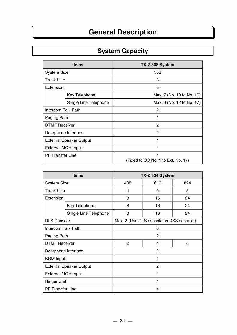
General Description
System Capacity
Items TX-Z 308 System
System Size 308
Trunk Line 3
Extension 8
Key Telephone Max. 7 (No. 10 to No. 16)
Single Line Telephone Max. 6 (No. 12 to No. 17)
Intercom Talk Path 2
Paging Path 1
DTMF Receiver 2
Doorphone Interface 2
External Speaker Output 1
External MOH Input 1
PF Transfer Line 1(Fixed to CO No. 1 to Ext. No. 17)
Items TX-Z 824 System
System Size 408 616 824
Trunk Line 4 6 8
Extension 8 16 24
Key Telephone 8 16 24
Single Line Telephone 8 16 24
DLS Console Max. 3 (Use DLS console as DSS console.)
Intercom Talk Path 6
Paging Path 2
DTMF Receiver 2 4 6
Doorphone Interface 2
BGM Input 1
External Speaker Output 2
External MOH Input 1
Ringer Unit 1
PF Transfer Line 4
2-2
General Description
System Capacity
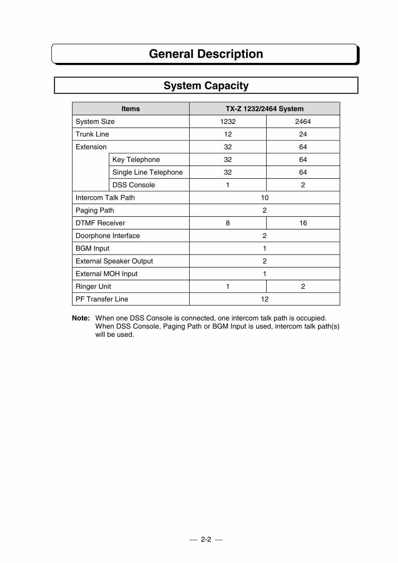
Items TX-Z 1232/2464 System
System Size 1232 2464
Trunk Line 12 24
Extension 32 64
Key Telephone 32 64
Single Line Telephone 32 64
DSS Console 1 2
Intercom Talk Path 10
Paging Path 2
DTMF Receiver 8 16
Doorphone Interface 2
BGM Input 1
External Speaker Output 2
External MOH Input 1
Ringer Unit 1 2
PF Transfer Line 12
Note: When one DSS Console is connected, one intercom talk path is occupied.When DSS Console, Paging Path or BGM Input is used, intercom talk path(s)will be used.
2-3
General Description
Electrical Specifications
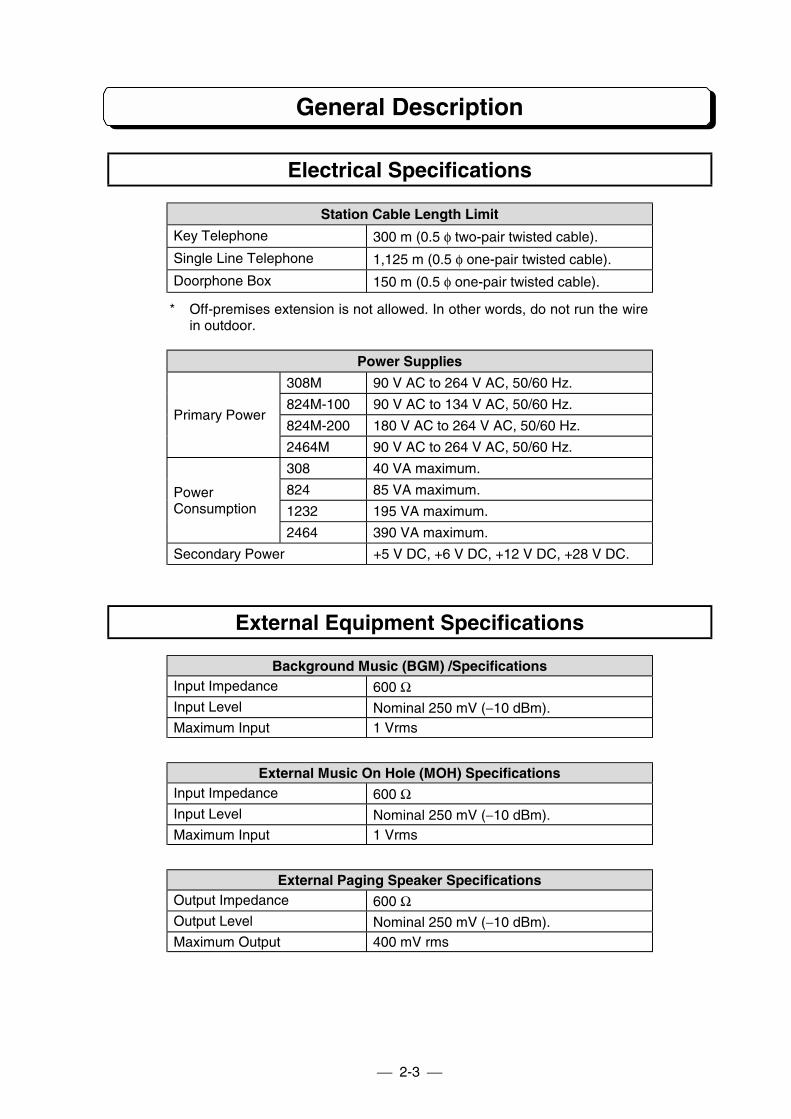
Station Cable Length Limit
Key Telephone 300 m (0.5 φ two-pair twisted cable).
Single Line Telephone 1,125 m (0.5 φ one-pair twisted cable).
Doorphone Box 150 m (0.5 φ one-pair twisted cable).
* Off-premises extension is not allowed. In other words, do not run the wirein outdoor.
Power Supplies
308M 90 V AC to 264 V AC, 50/60 Hz.
824M-100 90 V AC to 134 V AC, 50/60 Hz.
824M-200 180 V AC to 264 V AC, 50/60 Hz.Primary Power
2464M 90 V AC to 264 V AC, 50/60 Hz.
308 40 VA maximum.
824 85 VA maximum.
1232 195 VA maximum.PowerConsumption
2464 390 VA maximum.
Secondary Power +5 V DC, +6 V DC, +12 V DC, +28 V DC.
External Equipment Specifications
Background Music (BGM) /SpecificationsInput Impedance 600 ΩInput Level Nominal 250 mV (−10 dBm).Maximum Input 1 Vrms
External Music On Hole (MOH) SpecificationsInput Impedance 600 ΩInput Level Nominal 250 mV (−10 dBm).Maximum Input 1 Vrms
External Paging Speaker SpecificationsOutput Impedance 600 ΩOutput Level Nominal 250 mV (−10 dBm).Maximum Output 400 mV rms
2-4
General Description
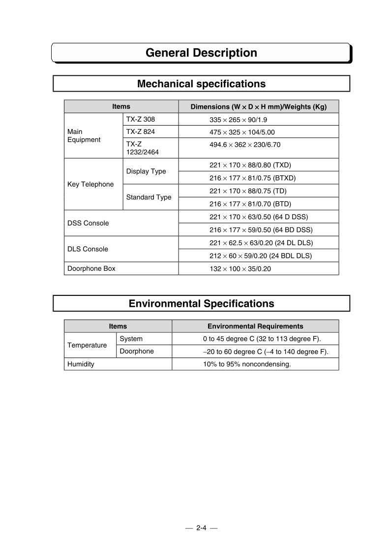
Mechanical specifications
Items Dimensions (W ×××× D ×××× H mm)/Weights (Kg)
TX-Z 308 335 × 265 × 90/1.9
TX-Z 824 475 × 325 × 104/5.00MainEquipment
TX-Z1232/2464
494.6 × 362 × 230/6.70
221 × 170 × 88/0.80 (TXD)Display Type
216 × 177 × 81/0.75 (BTXD)
221 × 170 × 88/0.75 (TD)Key Telephone
Standard Type216 × 177 × 81/0.70 (BTD)
221 × 170 × 63/0.50 (64 D DSS)DSS Console
216 × 177 × 59/0.50 (64 BD DSS)
221 × 62.5 × 63/0.20 (24 DL DLS)DLS Console
212 × 60 × 59/0.20 (24 BDL DLS)
Doorphone Box 132 × 100 × 35/0.20
Environmental Specifications
Items Environmental Requirements
System 0 to 45 degree C (32 to 113 degree F).Temperature
Doorphone −20 to 60 degree C (−4 to 140 degree F).
Humidity 10% to 95% noncondensing.
2-5
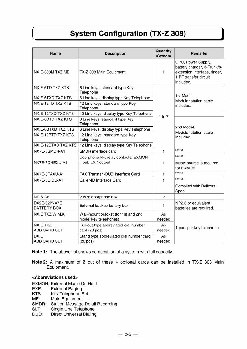
System Configuration (TX-Z 308)
Name DescriptionQuantity/System
Remarks
NX.E-308M TXZ ME TX-Z 308 Main Equipment 1
CPU, Power Supply,battery charger, 3-Trunk/8-extension interface, ringer,1 PF transfer circuitincluded.
NX.E-6TD TXZ KTS 6 Line keys, standard type KeyTelephone
NX.E-6TXD TXZ KTS 6 Line keys, display type Key TelephoneNX.E-12TD TXZ KTS 12 Line keys, standard type Key
TelephoneNX.E-12TXD TXZ KTS 12 Line keys, display type Key Telephone
1st Model.Modular station cableincluded.
NX.E-6BTD TXZ KTS 6 Line keys, standard type KeyTelephone
NX.E-6BTXD TXZ KTS 6 Line keys, display type Key TelephoneNX.E-12BTD TXZ KTS 12 Line keys, standard type Key
TelephoneNX.E-12BTXD TXZ KTS 12 Line keys, display type Key Telephone
1 to 7
2nd Model.Modular station cableincluded.
NX7E-3SMDR-A1 SMDR interface card 1 Note 2
NX7E-3DHEXU-A1Doorphone I/F, relay contacts, EXMOHinput, EXP output 1
Note 2
Music source is requiredfor EXMOH.
NX7E-3FAXU-A1 FAX Transfer /DUD Interface Card 1 Note 2
NX7E-3CIDU-A1 Caller-ID Interface Card 1 Note 2
Complied with BellcoreSpec.
NT-S-D6 2-wire doorphone box 2
DX2E-32i/NX7EBATTERY BOX
External backup battery box 1NP2.6 or equivalentbatteries are required.
NX.E TXZ W.M.K Wall-mount bracket (for 1st and 2ndmodel key telephones)
Asneeded
NX.E TXZABB.CARD SET
Pull-out type abbreviated dial numbercard (20 pcs)
Asneeded
DX.EABB.CARD SET
Stand type abbreviated dial number card(20 pcs)
Asneeded
1 pce. per key telephone.
Note 1: The above list shows composition of a system with full capacity.
Note 2: A maximum of 2 out of these 4 optional cards can be installed in TX-Z 308 MainEquipment.
<Abbreviations used>EXMOH: External Music On HoldEXP: External PagingKTS: Key Telephone SetME: Main EquipmentSMDR: Station Message Detail RecordingSLT: Single Line TelephoneDUD: Direct Universal Dialing
2-6
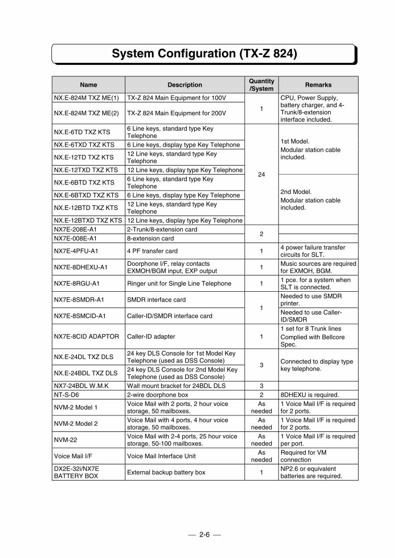
System Configuration (TX-Z 824)
Name Description Quantity/System
Remarks
NX.E-824M TXZ ME(1) TX-Z 824 Main Equipment for 100V
NX.E-824M TXZ ME(2) TX-Z 824 Main Equipment for 200V1
CPU, Power Supply,battery charger, and 4-Trunk/8-extensioninterface included.
NX.E-6TD TXZ KTS 6 Line keys, standard type KeyTelephone
NX.E-6TXD TXZ KTS 6 Line keys, display type Key Telephone
NX.E-12TD TXZ KTS 12 Line keys, standard type KeyTelephone
NX.E-12TXD TXZ KTS 12 Line keys, display type Key Telephone
1st Model.Modular station cableincluded.
NX.E-6BTD TXZ KTS 6 Line keys, standard type KeyTelephone
NX.E-6BTXD TXZ KTS 6 Line keys, display type Key Telephone
NX.E-12BTD TXZ KTS 12 Line keys, standard type KeyTelephone
NX.E-12BTXD TXZ KTS 12 Line keys, display type Key Telephone
24
2nd Model.Modular station cableincluded.
NX7E-208E-A1 2-Trunk/8-extension cardNX7E-008E-A1 8-extension card
2
NX7E-4PFU-A1 4 PF transfer card 1 4 power failure transfercircuits for SLT.
NX7E-8DHEXU-A1 Doorphone I/F, relay contactsEXMOH/BGM input, EXP output
1 Music sources are requiredfor EXMOH, BGM.
NX7E-8RGU-A1 Ringer unit for Single Line Telephone 1 1 pce. for a system whenSLT is connected.
NX7E-8SMDR-A1 SMDR interface card Needed to use SMDRprinter.
NX7E-8SMCID-A1 Caller-ID/SMDR interface card1
Needed to use Caller-ID/SMDR
NX7E-8CID ADAPTOR Caller-ID adapter 11 set for 8 Trunk linesComplied with BellcoreSpec.
NX.E-24DL TXZ DLS 24 key DLS Console for 1st Model KeyTelephone (used as DSS Console)
NX.E-24BDL TXZ DLS 24 key DLS Console for 2nd Model KeyTelephone (used as DSS Console)
3 Connected to display typekey telephone.
NX7-24BDL W.M.K Wall mount bracket for 24BDL DLS 3NT-S-D6 2-wire doorphone box 2 8DHEXU is required.
NVM-2 Model 1 Voice Mail with 2 ports, 2 hour voicestorage, 50 mailboxes.
Asneeded
1 Voice Mail I/F is requiredfor 2 ports.
NVM-2 Model 2 Voice Mail with 4 ports, 4 hour voicestorage, 50 mailboxes.
Asneeded
1 Voice Mail I/F is requiredfor 2 ports.
NVM-22 Voice Mail with 2-4 ports, 25 hour voicestorage, 50-100 mailboxes.
Asneeded
1 Voice Mail I/F is requiredper port.
Voice Mail I/F Voice Mail Interface Unit Asneeded
Required for VMconnection
DX2E-32i/NX7EBATTERY BOX
External backup battery box 1 NP2.6 or equivalentbatteries are required.
2-7
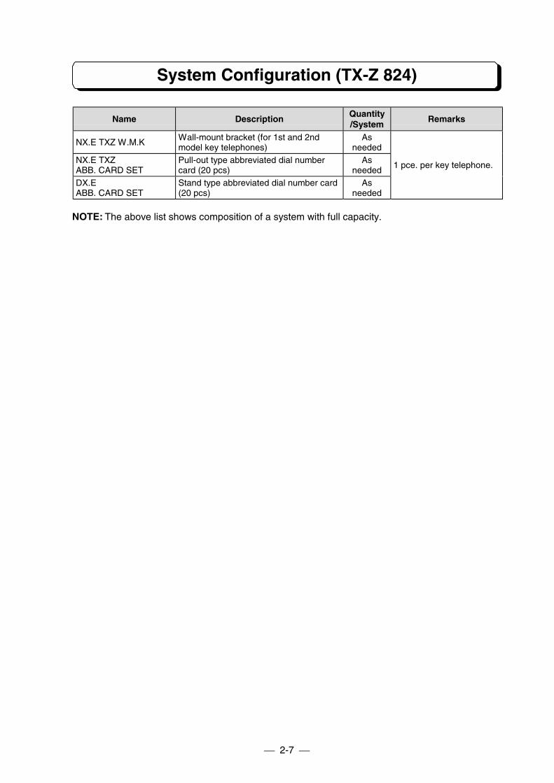
System Configuration (TX-Z 824)
Name Description Quantity/System
Remarks
NX.E TXZ W.M.K Wall-mount bracket (for 1st and 2ndmodel key telephones)
Asneeded
NX.E TXZABB. CARD SET
Pull-out type abbreviated dial numbercard (20 pcs)
Asneeded
DX.EABB. CARD SET
Stand type abbreviated dial number card(20 pcs)
Asneeded
1 pce. per key telephone.
NOTE: The above list shows composition of a system with full capacity.
2-8
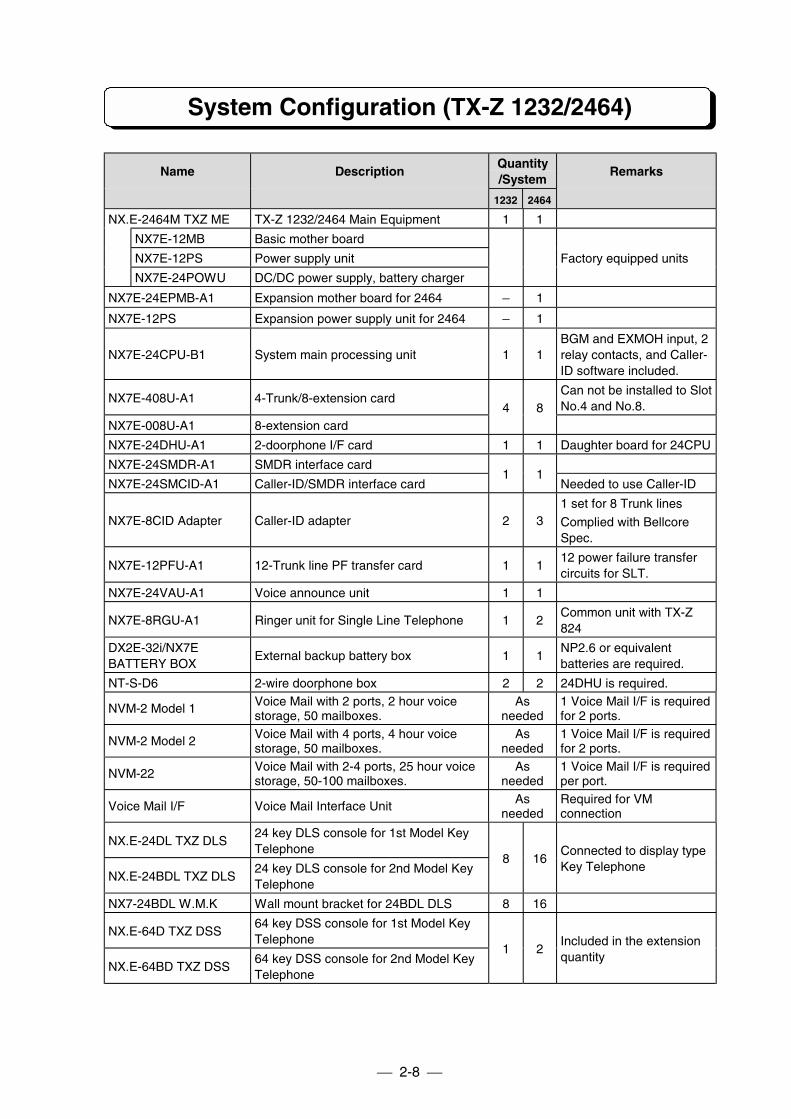
System Configuration (TX-Z 1232/2464)
Name DescriptionQuantity/System
Remarks
1232 2464
NX.E-2464M TXZ ME TX-Z 1232/2464 Main Equipment 1 1
NX7E-12MB Basic mother board
NX7E-12PS Power supply unit
NX7E-24POWU DC/DC power supply, battery charger
Factory equipped units
NX7E-24EPMB-A1 Expansion mother board for 2464 − 1
NX7E-12PS Expansion power supply unit for 2464 − 1
NX7E-24CPU-B1 System main processing unit 1 1BGM and EXMOH input, 2relay contacts, and Caller-ID software included.
NX7E-408U-A1 4-Trunk/8-extension cardCan not be installed to SlotNo.4 and No.8.
NX7E-008U-A1 8-extension card4 8
NX7E-24DHU-A1 2-doorphone I/F card 1 1 Daughter board for 24CPU
NX7E-24SMDR-A1 SMDR interface card
NX7E-24SMCID-A1 Caller-ID/SMDR interface card1 1
Needed to use Caller-ID
NX7E-8CID Adapter Caller-ID adapter 2 31 set for 8 Trunk lines
Complied with BellcoreSpec.
NX7E-12PFU-A1 12-Trunk line PF transfer card 1 112 power failure transfercircuits for SLT.
NX7E-24VAU-A1 Voice announce unit 1 1
NX7E-8RGU-A1 Ringer unit for Single Line Telephone 1 2Common unit with TX-Z824
DX2E-32i/NX7EBATTERY BOX
External backup battery box 1 1NP2.6 or equivalentbatteries are required.
NT-S-D6 2-wire doorphone box 2 2 24DHU is required.
NVM-2 Model 1 Voice Mail with 2 ports, 2 hour voicestorage, 50 mailboxes.
Asneeded
1 Voice Mail I/F is requiredfor 2 ports.
NVM-2 Model 2 Voice Mail with 4 ports, 4 hour voicestorage, 50 mailboxes.
Asneeded
1 Voice Mail I/F is requiredfor 2 ports.
NVM-22 Voice Mail with 2-4 ports, 25 hour voicestorage, 50-100 mailboxes.
Asneeded
1 Voice Mail I/F is requiredper port.
Voice Mail I/F Voice Mail Interface Unit Asneeded
Required for VMconnection
NX.E-24DL TXZ DLS24 key DLS console for 1st Model KeyTelephone
NX.E-24BDL TXZ DLS24 key DLS console for 2nd Model KeyTelephone
8 16Connected to display typeKey Telephone
NX7-24BDL W.M.K Wall mount bracket for 24BDL DLS 8 16
NX.E-64D TXZ DSS64 key DSS console for 1st Model KeyTelephone
NX.E-64BD TXZ DSS64 key DSS console for 2nd Model KeyTelephone
1 2Included in the extensionquantity
2-9
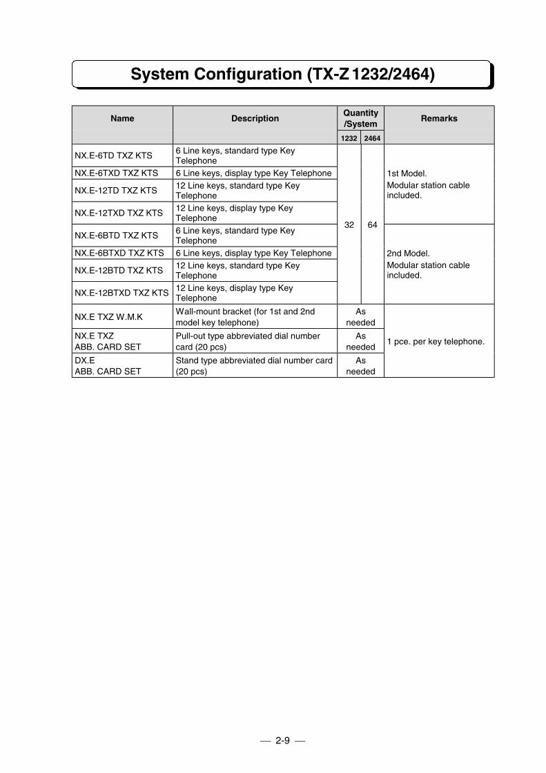
System Configuration (TX-Z 1232/2464)
Name DescriptionQuantity/System
Remarks
1232 2464
NX.E-6TD TXZ KTS 6 Line keys, standard type KeyTelephone
NX.E-6TXD TXZ KTS 6 Line keys, display type Key Telephone
NX.E-12TD TXZ KTS 12 Line keys, standard type KeyTelephone
NX.E-12TXD TXZ KTS 12 Line keys, display type KeyTelephone
1st Model.Modular station cableincluded.
NX.E-6BTD TXZ KTS 6 Line keys, standard type KeyTelephone
NX.E-6BTXD TXZ KTS 6 Line keys, display type Key Telephone
NX.E-12BTD TXZ KTS 12 Line keys, standard type KeyTelephone
NX.E-12BTXD TXZ KTS 12 Line keys, display type KeyTelephone
32 64
2nd Model.Modular station cableincluded.
NX.E TXZ W.M.KWall-mount bracket (for 1st and 2ndmodel key telephone)
Asneeded
NX.E TXZABB. CARD SET
Pull-out type abbreviated dial numbercard (20 pcs)
Asneeded
DX.EABB. CARD SET
Stand type abbreviated dial number card(20 pcs)
Asneeded
1 pce. per key telephone.
2-10
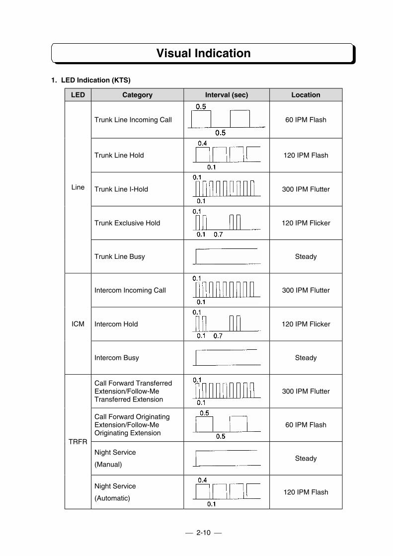
Visual Indication
1. LED Indication (KTS)
LED Category Interval (sec) Location
Trunk Line Incoming Call 60 IPM Flash
Trunk Line Hold 120 IPM Flash
Trunk Line I-Hold 300 IPM Flutter
Trunk Exclusive Hold 120 IPM Flicker
Line
Trunk Line Busy Steady
Intercom Incoming Call 300 IPM Flutter
Intercom Hold 120 IPM FlickerICM
Intercom Busy Steady
Call Forward TransferredExtension/Follow-MeTransferred Extension
300 IPM Flutter
Call Forward OriginatingExtension/Follow-MeOriginating Extension
60 IPM Flash
Night Service
(Manual)Steady
TRFR
Night Service
(Automatic)120 IPM Flash
2-11
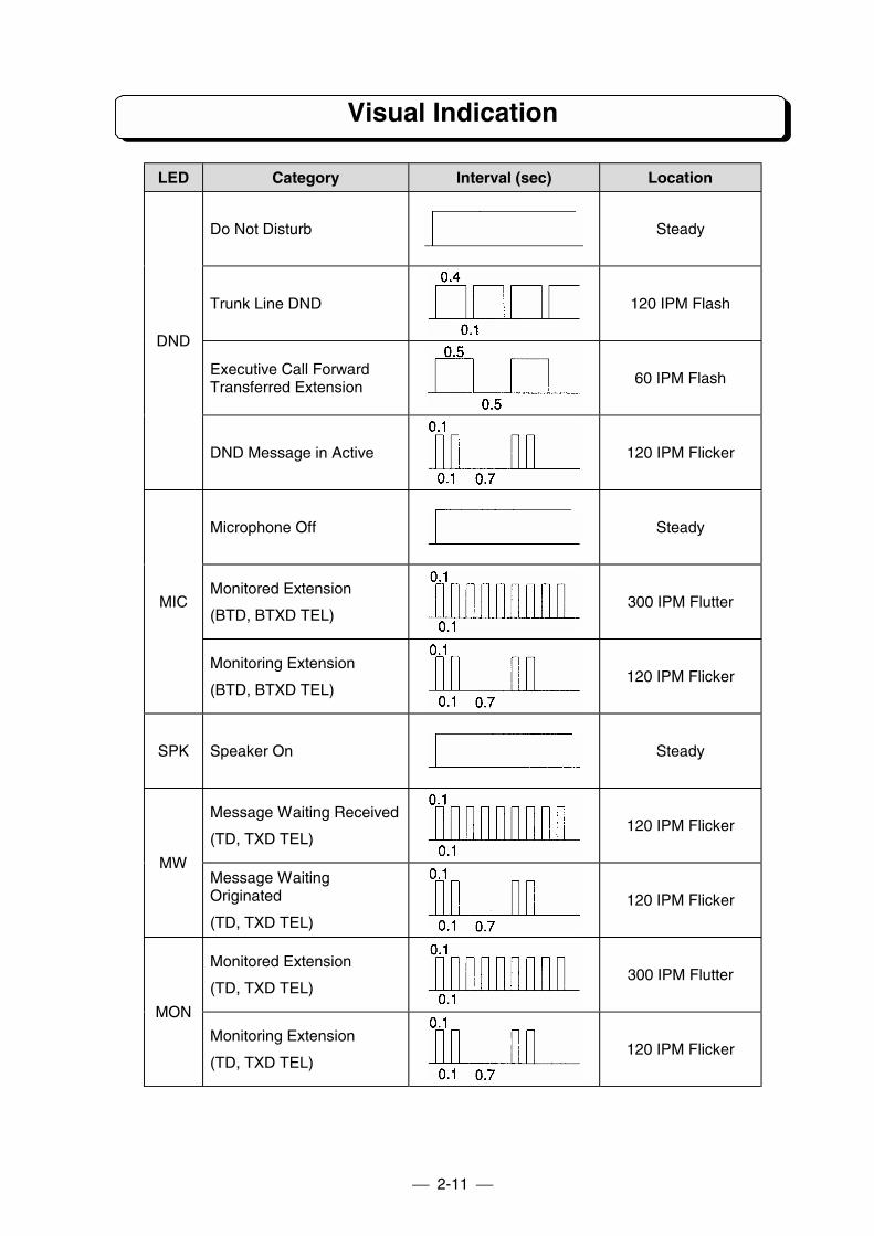
Visual Indication
LED Category Interval (sec) Location
Do Not Disturb Steady
Trunk Line DND 120 IPM Flash
Executive Call ForwardTransferred Extension
60 IPM Flash
DND
DND Message in Active 120 IPM Flicker
Microphone Off Steady
Monitored Extension
(BTD, BTXD TEL)300 IPM FlutterMIC
Monitoring Extension
(BTD, BTXD TEL)120 IPM Flicker
SPK Speaker On Steady
Message Waiting Received
(TD, TXD TEL)120 IPM Flicker
MWMessage WaitingOriginated
(TD, TXD TEL)120 IPM Flicker
Monitored Extension
(TD, TXD TEL)300 IPM Flutter
MON
Monitoring Extension
(TD, TXD TEL)120 IPM Flicker
2-12
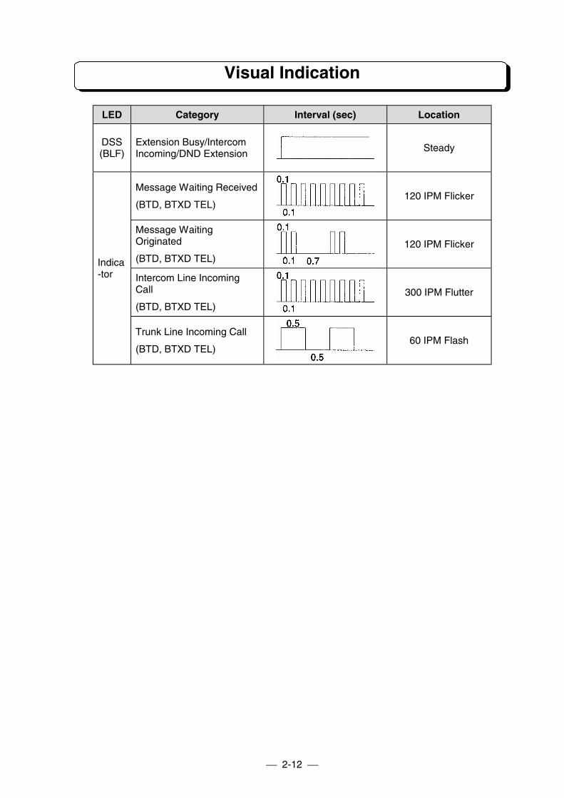
Visual Indication
LED Category Interval (sec) Location
DSS(BLF)
Extension Busy/IntercomIncoming/DND Extension
Steady
Message Waiting Received
(BTD, BTXD TEL)120 IPM Flicker
Message WaitingOriginated
(BTD, BTXD TEL)120 IPM Flicker
Intercom Line IncomingCall
(BTD, BTXD TEL)300 IPM Flutter
Indica-tor
Trunk Line Incoming Call
(BTD, BTXD TEL)60 IPM Flash
2-13
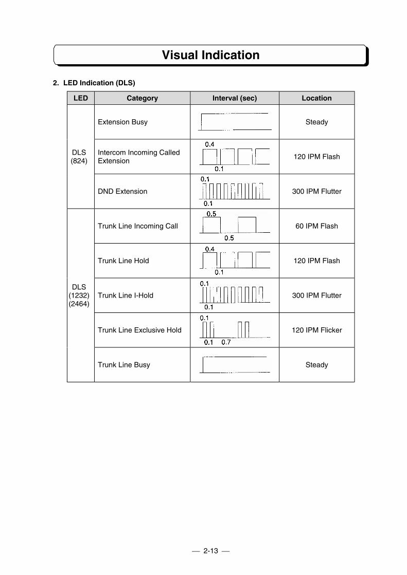
Visual Indication
2. LED Indication (DLS)
LED Category Interval (sec) Location
Extension Busy Steady
Intercom Incoming CalledExtension
120 IPM FlashDLS(824)
DND Extension 300 IPM Flutter
Trunk Line Incoming Call 60 IPM Flash
Trunk Line Hold 120 IPM Flash
Trunk Line I-Hold 300 IPM Flutter
Trunk Line Exclusive Hold 120 IPM Flicker
DLS(1232)(2464)
Trunk Line Busy Steady
2-14
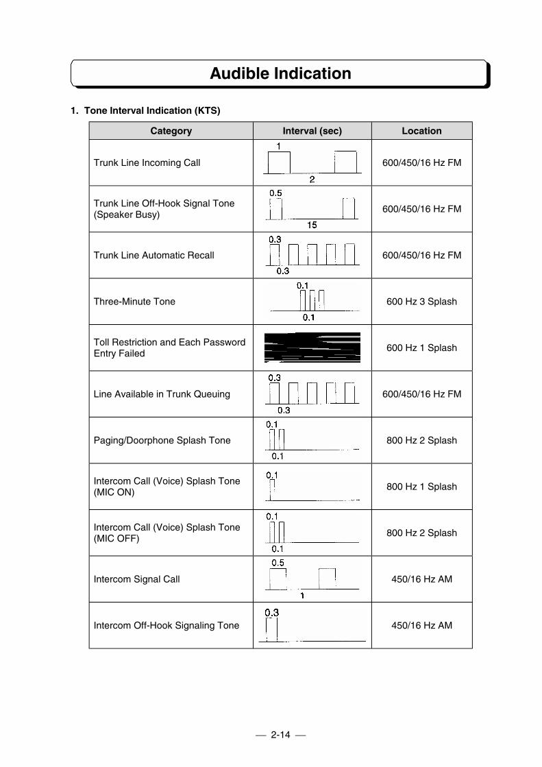
Audible Indication
1. Tone Interval Indication (KTS)
Category Interval (sec) Location
Trunk Line Incoming Call 600/450/16 Hz FM
Trunk Line Off-Hook Signal Tone(Speaker Busy)
600/450/16 Hz FM
Trunk Line Automatic Recall 600/450/16 Hz FM
Three-Minute Tone 600 Hz 3 Splash
Toll Restriction and Each PasswordEntry Failed
600 Hz 1 Splash
Line Available in Trunk Queuing 600/450/16 Hz FM
Paging/Doorphone Splash Tone 800 Hz 2 Splash
Intercom Call (Voice) Splash Tone(MIC ON)
800 Hz 1 Splash
Intercom Call (Voice) Splash Tone(MIC OFF)
800 Hz 2 Splash
Intercom Signal Call 450/16 Hz AM
Intercom Off-Hook Signaling Tone 450/16 Hz AM
2-15
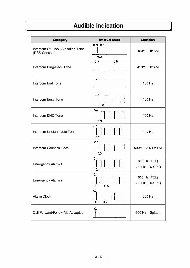
Audible Indication
Category Interval (sec) Location
Intercom Off-Hook Signaling Tone(DSS Console)
450/16 Hz AM
Intercom Ring-Back Tone 450/16 Hz AM
Intercom Dial Tone 400 Hz
Intercom Busy Tone 400 Hz
Intercom DND Tone 400 Hz
Intercom Unobtainable Tone 400 Hz
Intercom Callback Recall 600/450/16 Hz FM
Emergency Alarm 1600 Hz (TEL)
800 Hz (EX-SPK)
Emergency Alarm 2600 Hz (TEL)
800 Hz (EX-SPK)
Alarm Clock 600 Hz
Call Forward/Follow-Me Accepted 600 Hz 1 Splash
2-16
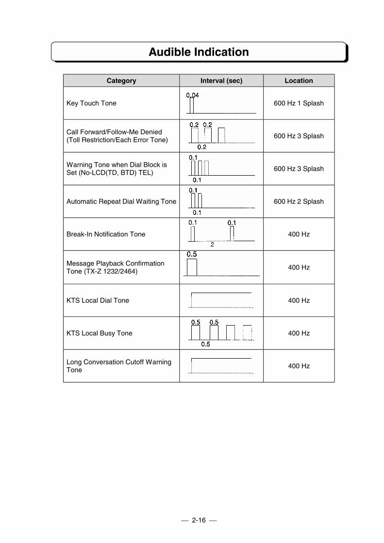
Audible Indication
Category Interval (sec) Location
Key Touch Tone 600 Hz 1 Splash
Call Forward/Follow-Me Denied(Toll Restriction/Each Error Tone)
600 Hz 3 Splash
Warning Tone when Dial Block isSet (No-LCD(TD, BTD) TEL)
600 Hz 3 Splash
Automatic Repeat Dial Waiting Tone 600 Hz 2 Splash
Break-In Notification Tone 400 Hz
Message Playback ConfirmationTone (TX-Z 1232/2464)
400 Hz
KTS Local Dial Tone 400 Hz
KTS Local Busy Tone 400 Hz
Long Conversation Cutoff WarningTone
400 Hz
2-17
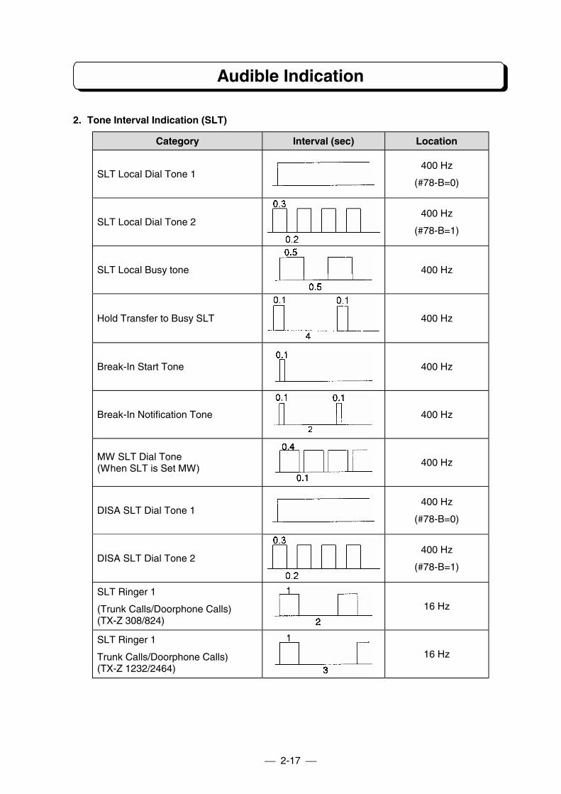
Audible Indication
2. Tone Interval Indication (SLT)
Category Interval (sec) Location
SLT Local Dial Tone 1400 Hz
(#78-B=0)
SLT Local Dial Tone 2400 Hz
(#78-B=1)
SLT Local Busy tone 400 Hz
Hold Transfer to Busy SLT 400 Hz
Break-In Start Tone 400 Hz
Break-In Notification Tone 400 Hz
MW SLT Dial Tone(When SLT is Set MW)
400 Hz
DISA SLT Dial Tone 1400 Hz
(#78-B=0)
DISA SLT Dial Tone 2400 Hz
(#78-B=1)
SLT Ringer 1
(Trunk Calls/Doorphone Calls)(TX-Z 308/824)
16 Hz
SLT Ringer 1
Trunk Calls/Doorphone Calls)(TX-Z 1232/2464)
16 Hz
2-18
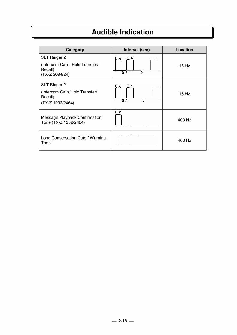
Audible Indication
Category Interval (sec) Location
SLT Ringer 2
(Intercom Calls/ Hold Transfer/Recall)(TX-Z 308/824)
16 Hz
SLT Ringer 2
(Intercom Calls/Hold Transfer/Recall)(TX-Z 1232/2464)
16 Hz
Message Playback ConfirmationTone (TX-Z 1232/2464)
400 Hz
Long Conversation Cutoff WarningTone
400 Hz
PART 3
SYSTEM INSTALLATION
Precaution
3-1 Installation of TX-Z 308 System
3-2 Installation of TX-Z 824 System
3-3 Installation of TX-Z 1232/2464 System
Precaution
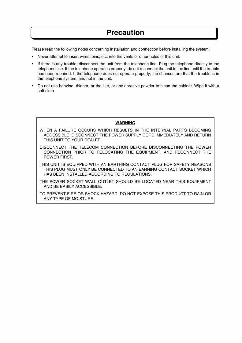
Please read the following notes concerning installation and connection before installing the system.
! Never attempt to insert wires, pins, etc. into the vents or other holes of this unit.
! If there is any trouble, disconnect the unit from the telephone line. Plug the telephone directly to thetelephone line. If the telephone operates properly, do not reconnect the unit to the line until the troublehas been repaired. If the telephone does not operate properly, the chances are that the trouble is inthe telephone system, and not in the unit.
! Do not use benzine, thinner, or the like, or any abrasive powder to clean the cabinet. Wipe it with asoft cloth.
WARNING
WHEN A FAILURE OCCURS WHICH RESULTS IN THE INTERNAL PARTS BECOMINGACCESSIBLE, DISCONNECT THE POWER SUPPLY CORD IMMEDIATELY AND RETURNTHIS UNIT TO YOUR DEALER.
DISCONNECT THE TELECOM CONNECTION BEFORE DISCONNECTING THE POWERCONNECTION PRIOR TO RELOCATING THE EQUIPMENT, AND RECONNECT THEPOWER FIRST.
THIS UNIT IS EQUIPPED WITH AN EARTHING CONTACT PLUG FOR SAFETY REASONSTHIS PLUG MUST ONLY BE CONNECTED TO AN EARNING CONTACT SOCKET WHICHHAS BEEN INSTALLED ACCORDING TO REGULATIONS.
THE POWER SOCKET WALL OUTLET SHOULD BE LOCATED NEAR THIS EQUIPMENTAND BE EASILY ACCESSIBLE.
TO PREVENT FIRE OR SHOCK HAZARD, DO NOT EXPOSE THIS PRODUCT TO RAIN ORANY TYPE OF MOISTURE.
Precaution
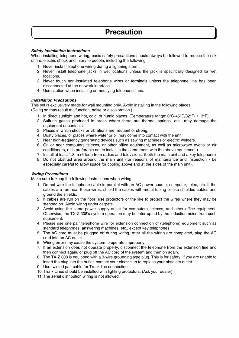
Safety Installation InstructionsWhen installing telephone wiring, basic safety precautions should always be followed to reduce the riskof fire, electric shock and injury to people, including the following:
1. Never install telephone wiring during a lightning storm.2. Never install telephone jacks in wet locations unless the jack is specifically designed for wet
locations.3. Never touch non-insulated telephone wires or terminals unless the telephone line has been
disconnected at the network interface.4. Use caution when installing or modifying telephone lines.
Installation PrecautionsThis set is exclusively made for wall mounting only. Avoid installing in the following places.(Doing so may result malfunction, noise or discoloration.)
1. In direct sunlight and hot, cold, or humid places. (Temperature range: 0°C-45°C/32°F- 113°F)2. Sulfuric gases produced in areas where there are thermal springs, etc., may damage the
equipment or contacts.3. Places in which shocks or vibrations are frequent or strong.4. Dusty places, or places where water or oil may come into contact with the unit.5. Near high-frequency generating devices such as sewing machines or electric welders.6. On or near computers telexes, or other office equipment, as well as microwave ovens or air
conditioners, (It is preferable not to install in the same room with the above equipment.)7. Install at least 1.8 m (6 feet) from radios and televisions. (both the main unit and a key telephone)8. Do not obstruct area around the main unit (for reasons of maintenance and inspection - be
especially careful to allow space for cooling above and at the sides of the main unit).
Wiring PrecautionsMake sure to keep the following instructions when wiring.
1. Do not wire the telephone cable in parallel with an AC power source, computer, telex, etc. If thecables are run near those wires, shield the cables with metal tubing or use shielded cables andground the shields.
2. If cables are run on the floor, use protectors or the like to protect the wires where they may bestepped on. Avoid wiring under carpets.
3. Avoid using the same power supply outlet for computers, telexes, and other office equipment.Otherwise, the TX-Z 308's system operation may be interrupted by the induction noise from suchequipment.
4. Please use one pair telephone wire for extension connection of (telephone) equipment such asstandard telephones, answering machines, etc., except key telephones.
5. The AC cord must be plugged off during wiring. After all the wiring are completed, plug the ACcord into an AC outlet.
6. Wiring error may cause the system to operate improperly.7. If an extension does not operate properly, disconnect the telephone from the extension line and
then connect again, or plug off the AC cord of the system and then on again.8. The TX-Z 308 is equipped with a 3-wire grounding type plug. This is for safety. If you are unable to
insert the plug into the outlet, contact your electrician to replace your obsolete outlet.9. Use twisted pair cable for Trunk line connection.10.Trunk Lines should be installed with lighting protectors. (Ask your dealer)11.The aerial distribution wiring is not allowed.
PART3-1
INSTALLATION OFTX-Z 308 SYSTEM
Table of Contents
Name and Location....................................................................................... 3-1-1Wall Mounting ............................................................................................... 3-1-1Opening Front Cover..................................................................................... 3-1-2Frame Ground Connection ........................................................................... 3-1-2Extension Connection ................................................................................... 3-1-2Trunk Line Connection.................................................................................. 3-1-4Installation of 3SMDR and Printer/PC .......................................................... 3-1-5Installation of 3DHEXU ................................................................................. 3-1-8After Wiring.................................................................................................. 3-1-1124 V DC Battery Supply .............................................................................. 3-1-11
Note: Refer to PART 7 for installation of 3CIDU-A1 and 3FAXU-A1.
3-1-1
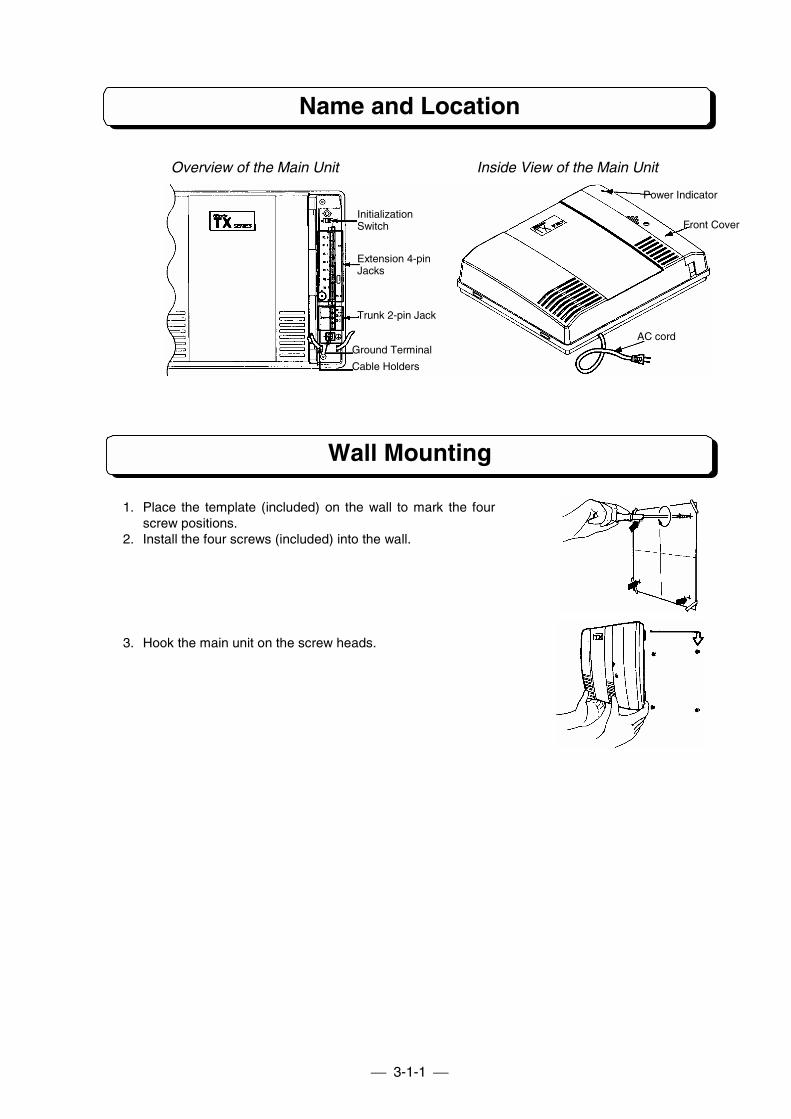
Name and Location
Wall Mounting
1. Place the template (included) on the wall to mark the fourscrew positions.
2. Install the four screws (included) into the wall.
3. Hook the main unit on the screw heads.
Overview of the Main Unit Inside View of the Main Unit
AC cord
Front Cover
Power Indicator
Ground Terminal
Cable Holders
Trunk 2-pin Jack
Extension 4-pinJacks
InitializationSwitch
3-1-2
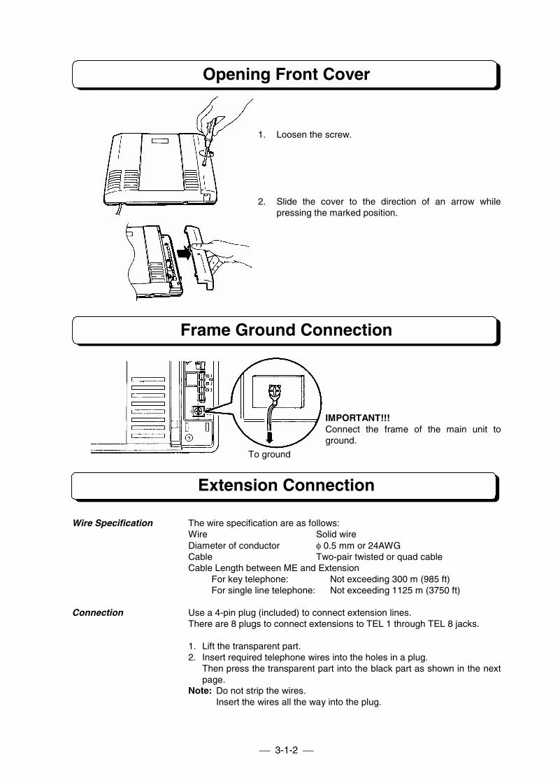
Opening Front Cover
1. Loosen the screw.
2. Slide the cover to the direction of an arrow whilepressing the marked position.
Frame Ground Connection
IMPORTANT!!!Connect the frame of the main unit toground.
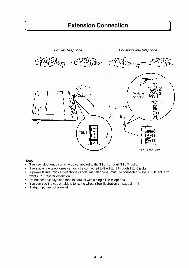
Extension Connection
Wire Specification The wire specification are as follows:Wire Solid wireDiameter of conductor φ 0.5 mm or 24AWGCable Two-pair twisted or quad cableCable Length between ME and Extension
For key telephone: Not exceeding 300 m (985 ft)For single line telephone: Not exceeding 1125 m (3750 ft)
Connection Use a 4-pin plug (included) to connect extension lines.There are 8 plugs to connect extensions to TEL 1 through TEL 8 jacks.
1. Lift the transparent part.2. Insert required telephone wires into the holes in a plug.
Then press the transparent part into the black part as shown in the nextpage.
Note: Do not strip the wires.Insert the wires all the way into the plug.
To ground
3-1-3
Extension Connection
Notes:! The key telephones can only be connected to the TEL 1 through TEL 7 jacks.! The single line telephones can only be connected to the TEL 3 through TEL 8 jacks.! A power failure transfer telephone (single line telephone) must be connected to the TEL 8 jack if you
want a PF transfer extension.! Do not connect key telephone in parallel with a single line telephone.! You can use the cable holders to fix the wires. (See illustration on page 3-1-11)! Bridge taps are not allowed.
TEL 1
Key Telephone
ModularAdapter
For key telephone For single line telephone
3-1-4
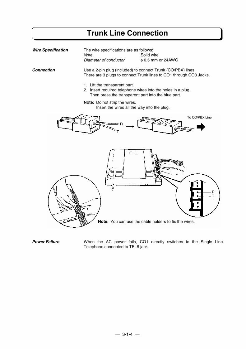
Trunk Line Connection
Wire Specification The wire specifications are as follows:Wire Solid wireDiameter of conductor φ 0.5 mm or 24AWG
Connection Use a 2-pin plug (included) to connect Trunk (CO/PBX) lines.There are 3 plugs to connect Trunk lines to CO1 through CO3 Jacks.
1. Lift the transparent part.2. Insert required telephone wires into the holes in a plug.
Then press the transparent part into the blue part.
Note: Do not strip the wires.Insert the wires all the way into the plug.
Power Failure When the AC power fails, CO1 directly switches to the Single LineTelephone connected to TEL8 jack.
Note: You can use the cable holders to fix the wires.
To CO/PBX Line
3-1-5
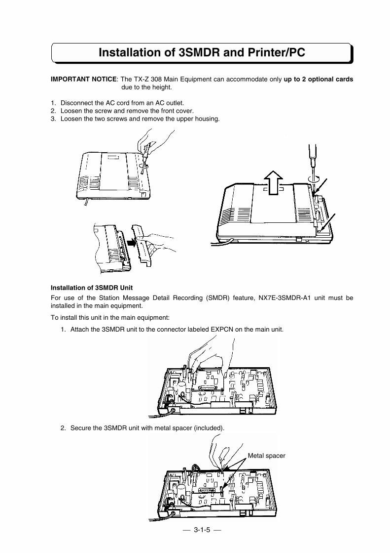
Installation of 3SMDR and Printer/PC
IMPORTANT NOTICE: The TX-Z 308 Main Equipment can accommodate only up to 2 optional cardsdue to the height.
1. Disconnect the AC cord from an AC outlet.2. Loosen the screw and remove the front cover.3. Loosen the two screws and remove the upper housing.
Installation of 3SMDR Unit
For use of the Station Message Detail Recording (SMDR) feature, NX7E-3SMDR-A1 unit must beinstalled in the main equipment.
To install this unit in the main equipment:
1. Attach the 3SMDR unit to the connector labeled EXPCN on the main unit.
2. Secure the 3SMDR unit with metal spacer (included).
Metal spacer
3-1-6
Installation of 3SMDR and Printer/PC
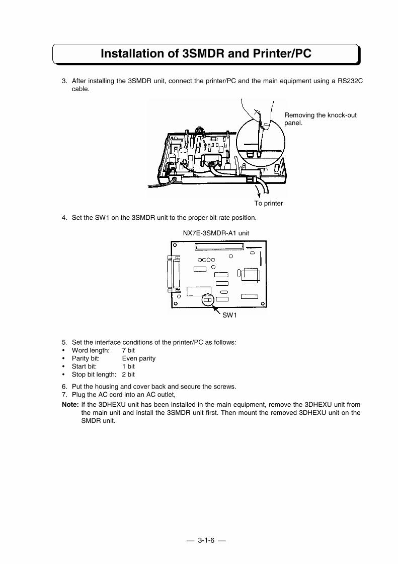
3. After installing the 3SMDR unit, connect the printer/PC and the main equipment using a RS232Ccable.
4. Set the SW1 on the 3SMDR unit to the proper bit rate position.
5. Set the interface conditions of the printer/PC as follows:! Word length: 7 bit! Parity bit: Even parity! Start bit: 1 bit! Stop bit length: 2 bit
6. Put the housing and cover back and secure the screws.7. Plug the AC cord into an AC outlet,
Note: If the 3DHEXU unit has been installed in the main equipment, remove the 3DHEXU unit fromthe main unit and install the 3SMDR unit first. Then mount the removed 3DHEXU unit on theSMDR unit.
Removing the knock-outpanel.
To printer
NX7E-3SMDR-A1 unit
SW1
3-1-7
Installation of 3SMDR and Printer/PC
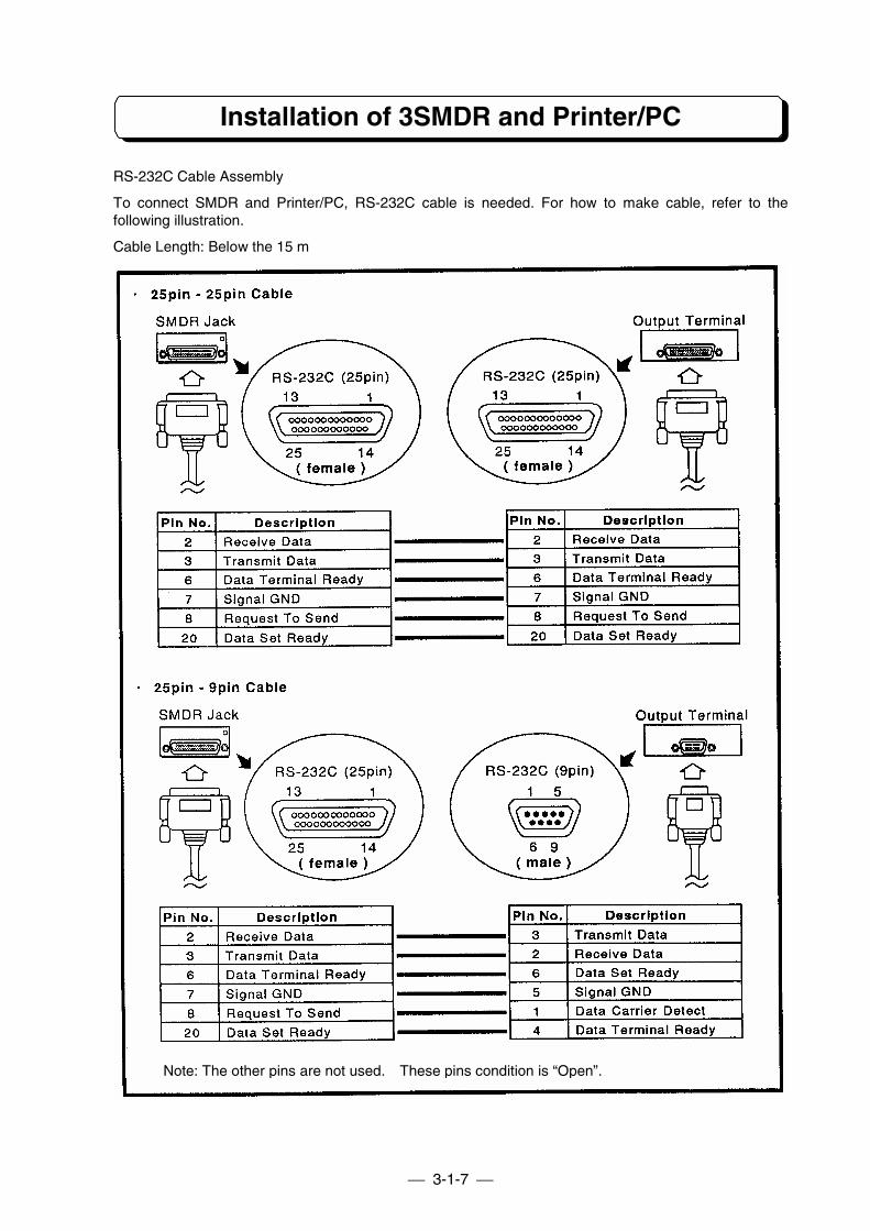
RS-232C Cable Assembly
To connect SMDR and Printer/PC, RS-232C cable is needed. For how to make cable, refer to thefollowing illustration.
Cable Length: Below the 15 m
Note: The other pins are not used. These pins condition is “Open”.
3-1-8
Installation of 3DHEXU
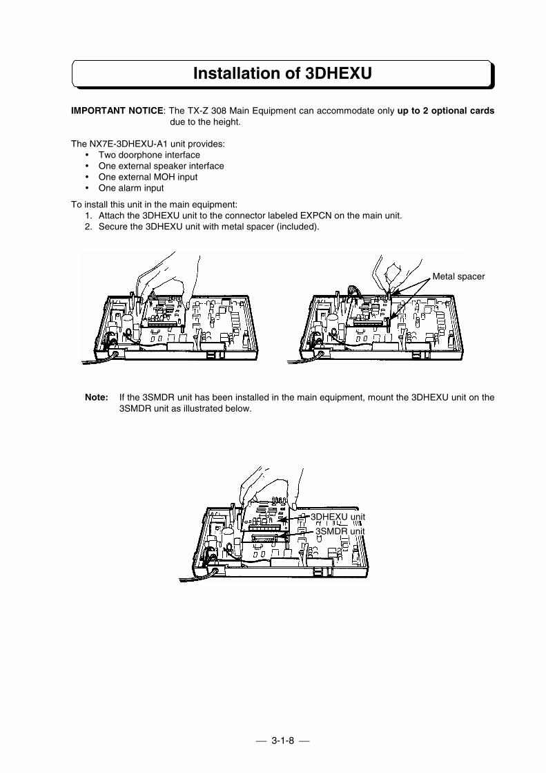
IMPORTANT NOTICE: The TX-Z 308 Main Equipment can accommodate only up to 2 optional cardsdue to the height.
The NX7E-3DHEXU-A1 unit provides:! Two doorphone interface! One external speaker interface! One external MOH input! One alarm input
To install this unit in the main equipment:1. Attach the 3DHEXU unit to the connector labeled EXPCN on the main unit.2. Secure the 3DHEXU unit with metal spacer (included).
Note: If the 3SMDR unit has been installed in the main equipment, mount the 3DHEXU unit on the3SMDR unit as illustrated below.
Metal spacer
3DHEXU unit
3SMDR unit
3-1-9
Installation of 3DHEXU
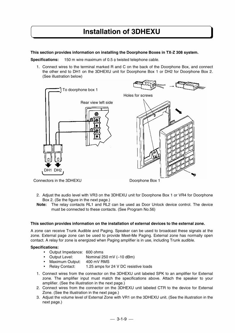
This section provides information on installing the Doorphone Boxes in TX-Z 308 system.
Specifications: 150 m wire maximum of 0.5 φ twisted telephone cable.
1. Connect wires to the terminal marked R and C on the back of the Doorphone Box, and connectthe other end to DH1 on the 3DHEXU unit for Doorphone Box 1 or DH2 for Doorphone Box 2.(See illustration below)
2. Adjust the audio level with VR3 on the 3DHEXU unit for Doorphone Box 1 or VR4 for DoorphoneBox 2. (Se the figure in the next page.)
Note: The relay contacts RL1 and RL2 can be used as Door Unlock device control. The devicemust be connected to these contacts. (See Program No.56)
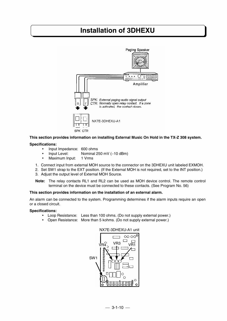
This section provides information on the installation of external devices to the external zone.
A zone can receive Trunk Audible and Paging. Speaker can be used to broadcast these signals at thezone. External page zone can be used to provide Meet-Me Paging. External zone has normally opencontact. A relay for zone is energized when Paging amplifier is in use, including Trunk audible.
Specifications:! Output Impedance: 600 ohms! Output Level: Nominal 250 mV (−10 dBm)! Maximum Output: 400 mV RMS! Relay Contact: 1.25 amps for 24 V DC resistive loads
1. Connect wires from the connector on the 3DHEXU unit labeled SPK to an amplifier for Externalzone. The amplifier input must match the specifications above. Attach the speaker to youramplifier. (See the illustration in the next page.)
2. Connect wires from the connector on the 3DHEXU unit labeled CTR to the device for ExternalZone. (See the illustration in the next page.)
3. Adjust the volume level of External Zone with VR1 on the 3DHEXU unit. (See the illustration in thenext page.)
Holes for screws
Rear view left side
To doorphone box 1
DH1 DH2
Connectors in the 3DHEXU Doorphone Box 1
3-1-10
Installation of 3DHEXU
This section provides information on installing External Music On Hold in the TX-Z 308 system.
Specifications:! Input Impedance: 600 ohms! Input Level: Nominal 250 mV (−10 dBm)! Maximum Input: 1 Vrms
1. Connect input from external MOH source to the connector on the 3DHEXU unit labeled EXMOH.2. Set SW1 strap to the EXT position. (If the External MOH is not required, set to the INT position.)3. Adjust the output level of External MOH Source.
Note: The relay contacts RL1 and RL2 can be used as MOH device control. The remote controlterminal on the device must be connected to these contacts. (See Program No. 56)
This section provides information on the installation of an external alarm.
An alarm can be connected to the system. Programming determines if the alarm inputs require an openor a closed circuit.
Specifications:! Loop Resistance: Less than 100 ohms. (Do not supply external power.)! Open Resistance: More than 5 kohms. (Do not supply external power.)
NX7E-3DHEXU-A1 unit
SW1
VR4 VR3 VR1
3-1-11
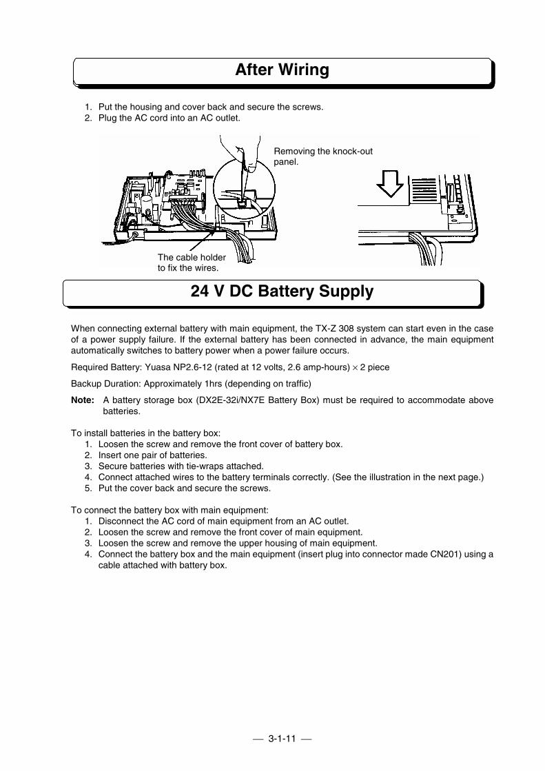
After Wiring
1. Put the housing and cover back and secure the screws.2. Plug the AC cord into an AC outlet.
24 V DC Battery Supply
When connecting external battery with main equipment, the TX-Z 308 system can start even in the caseof a power supply failure. If the external battery has been connected in advance, the main equipmentautomatically switches to battery power when a power failure occurs.
Required Battery: Yuasa NP2.6-12 (rated at 12 volts, 2.6 amp-hours) × 2 piece
Backup Duration: Approximately 1hrs (depending on traffic)
Note: A battery storage box (DX2E-32i/NX7E Battery Box) must be required to accommodate abovebatteries.
To install batteries in the battery box:1. Loosen the screw and remove the front cover of battery box.2. Insert one pair of batteries.3. Secure batteries with tie-wraps attached.4. Connect attached wires to the battery terminals correctly. (See the illustration in the next page.)5. Put the cover back and secure the screws.
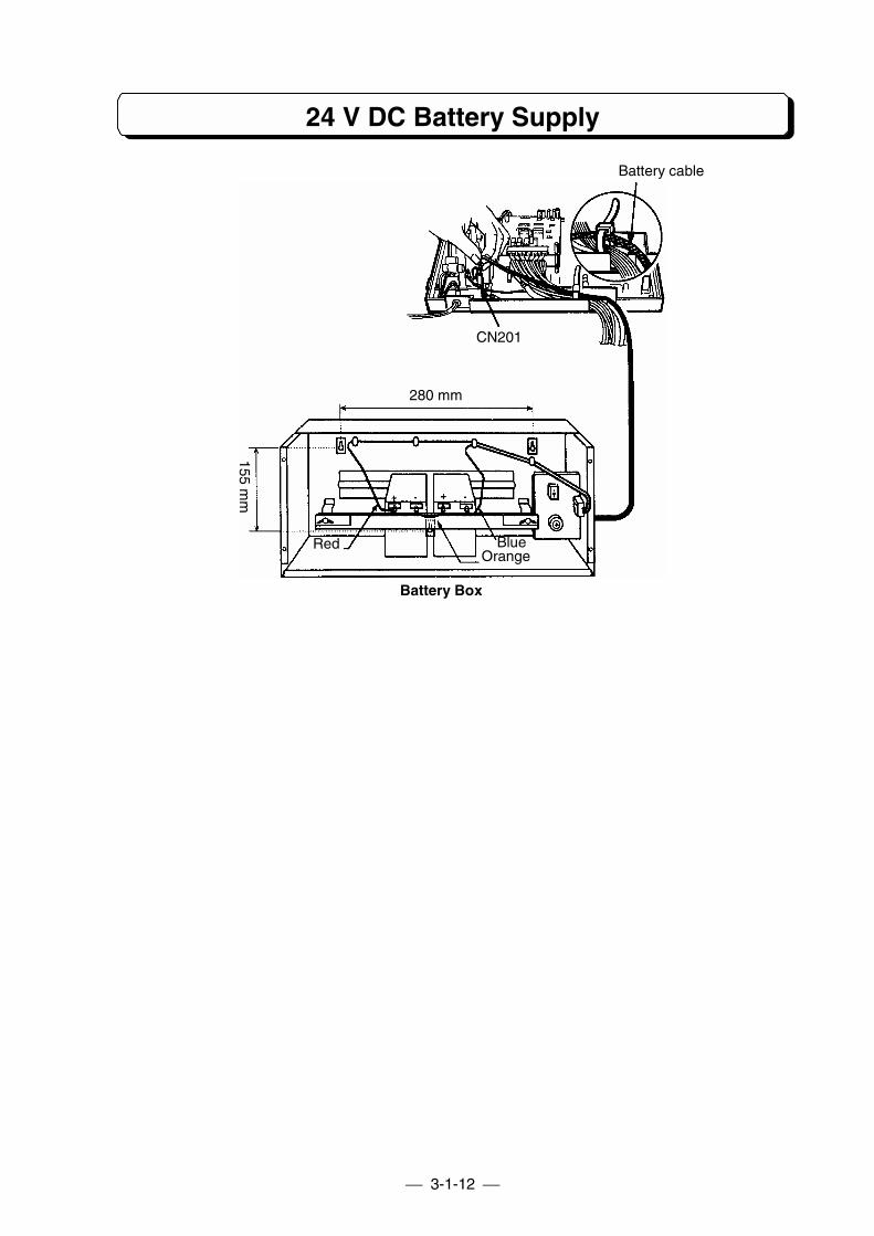
To connect the battery box with main equipment:1. Disconnect the AC cord of main equipment from an AC outlet.2. Loosen the screw and remove the front cover of main equipment.3. Loosen the screw and remove the upper housing of main equipment.4. Connect the battery box and the main equipment (insert plug into connector made CN201) using a
cable attached with battery box.
The cable holderto fix the wires.
Removing the knock-outpanel.
3-1-12
24 V DC Battery Supply
Battery Box
BlueOrange
Red
155 mm
280 mm
CN201
Battery cable

PART3-2
INSTALLATION OFTX-Z 824 SYSTEM

Table of Contents
Installing the Main Equipment....................................................................... 3-2-1The Card Locations....................................................................................... 3-2-2Grounding Requirements.............................................................................. 3-2-2Connector Assembly ..................................................................................... 3-2-3Trunk Line Connection.................................................................................. 3-2-3Extension Connection ................................................................................... 3-2-4Cable Routing and Cramping........................................................................ 3-2-5Installing Expansion PCBs............................................................................ 3-2-5Installing DLS Console.................................................................................. 3-2-5Installing the Ringer Unit............................................................................... 3-2-6Installing the SMDR and Printer/PC ............................................................. 3-2-6Installing 4PFU-A1 PCB................................................................................ 3-2-7Installing 8DHEXU-A1 PCB .......................................................................... 3-2-7Installing the Doorphone Box........................................................................ 3-2-8Installing External Paging Output ................................................................. 3-2-9Installing External MOH and BGM.............................................................. 3-2-10Installing External Alarm Sensor................................................................. 3-2-11Lithium Battery Installation.......................................................................... 3-2-11Backup Battery Connection ........................................................................ 3-2-12
Note: Refer to PART 7-1 for installation of 8SMCID-A1
3-2-1
Installing the Main Equipment
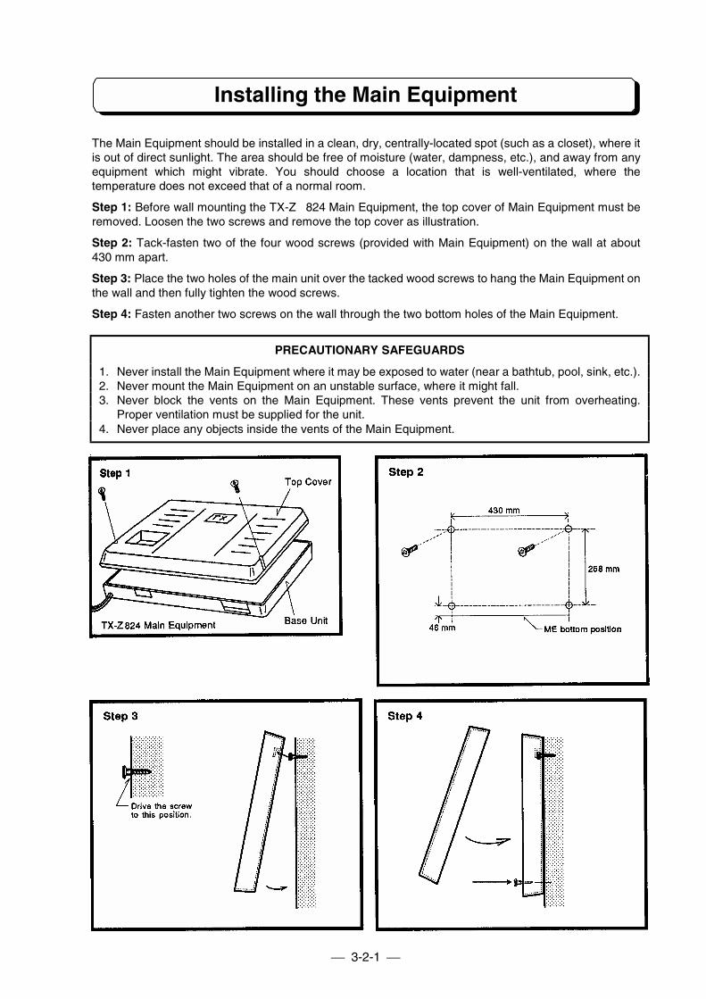
The Main Equipment should be installed in a clean, dry, centrally-located spot (such as a closet), where itis out of direct sunlight. The area should be free of moisture (water, dampness, etc.), and away from anyequipment which might vibrate. You should choose a location that is well-ventilated, where thetemperature does not exceed that of a normal room.
Step 1: Before wall mounting the TX-Z 824 Main Equipment, the top cover of Main Equipment must beremoved. Loosen the two screws and remove the top cover as illustration.
Step 2: Tack-fasten two of the four wood screws (provided with Main Equipment) on the wall at about430 mm apart.
Step 3: Place the two holes of the main unit over the tacked wood screws to hang the Main Equipment onthe wall and then fully tighten the wood screws.
Step 4: Fasten another two screws on the wall through the two bottom holes of the Main Equipment.
PRECAUTIONARY SAFEGUARDS
1. Never install the Main Equipment where it may be exposed to water (near a bathtub, pool, sink, etc.).2. Never mount the Main Equipment on an unstable surface, where it might fall.3. Never block the vents on the Main Equipment. These vents prevent the unit from overheating.
Proper ventilation must be supplied for the unit.4. Never place any objects inside the vents of the Main Equipment.
3-2-2
The Card Locations
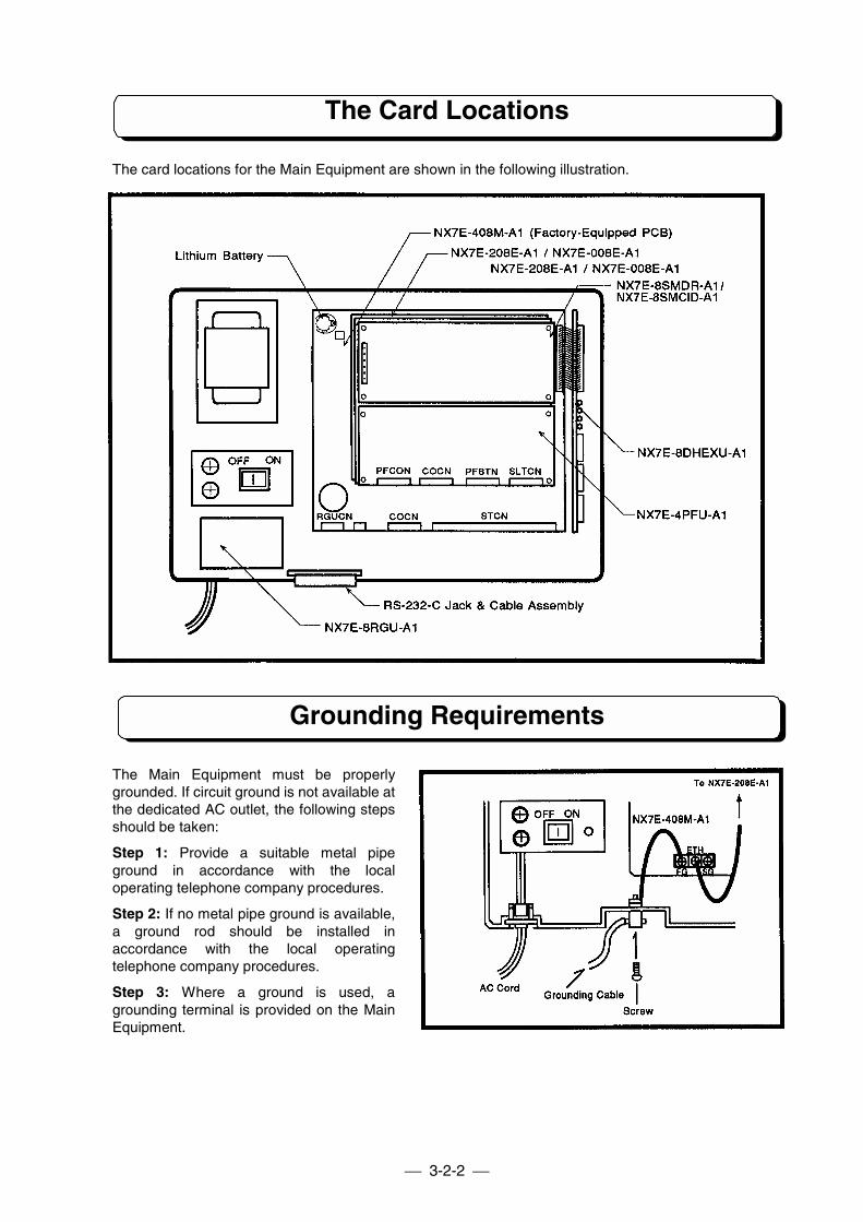
The card locations for the Main Equipment are shown in the following illustration.
Grounding Requirements
The Main Equipment must be properlygrounded. If circuit ground is not available atthe dedicated AC outlet, the following stepsshould be taken:
Step 1: Provide a suitable metal pipeground in accordance with the localoperating telephone company procedures.
Step 2: If no metal pipe ground is available,a ground rod should be installed inaccordance with the local operatingtelephone company procedures.
Step 3: Where a ground is used, agrounding terminal is provided on the MainEquipment.
3-2-3
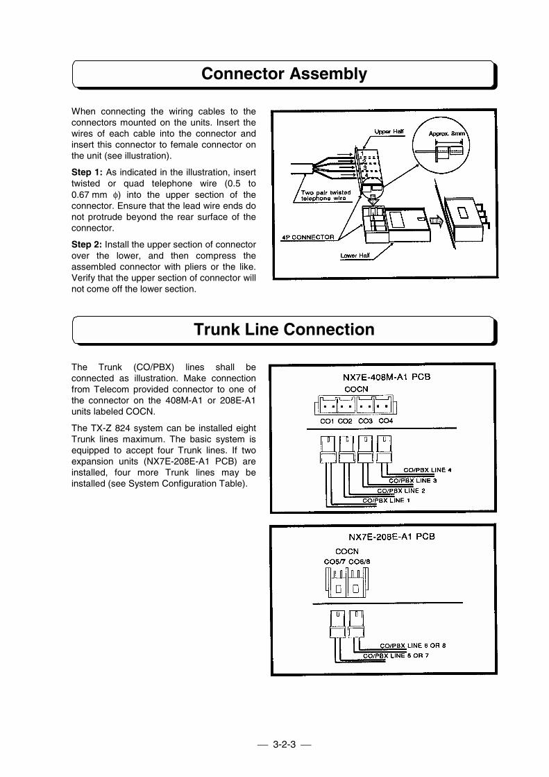
Connector Assembly
When connecting the wiring cables to theconnectors mounted on the units. Insert thewires of each cable into the connector andinsert this connector to female connector onthe unit (see illustration).
Step 1: As indicated in the illustration, inserttwisted or quad telephone wire (0.5 to0.67 mm φ) into the upper section of theconnector. Ensure that the lead wire ends donot protrude beyond the rear surface of theconnector.
Step 2: Install the upper section of connectorover the lower, and then compress theassembled connector with pliers or the like.Verify that the upper section of connector willnot come off the lower section.
Trunk Line Connection
The Trunk (CO/PBX) lines shall beconnected as illustration. Make connectionfrom Telecom provided connector to one ofthe connector on the 408M-A1 or 208E-A1units labeled COCN.
The TX-Z 824 system can be installed eightTrunk lines maximum. The basic system isequipped to accept four Trunk lines. If twoexpansion units (NX7E-208E-A1 PCB) areinstalled, four more Trunk lines may beinstalled (see System Configuration Table).
3-2-4
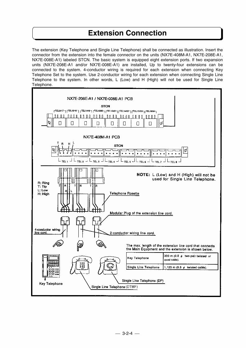
Extension Connection
The extension (Key Telephone and Single Line Telephone) shall be connected as illustration. Insert theconnector from the extension into the female connector on the units (NX7E-408M-A1, NX7E-208E-A1,NX7E-008E-A1) labeled STCN. The basic system is equipped eight extension ports. If two expansionunits (NX7E-208E-A1 and/or NX7E-008E-A1) are installed, Up to twenty-four extensions can beconnected to the system. 4-conductor wiring is required for each extension when connecting KeyTelephone Set to the system. Use 2-conductor wiring for each extension when connecting Single LineTelephone to the system. In other words, L (Low) and H (High) will not be used for Single LineTelephone.
3-2-5
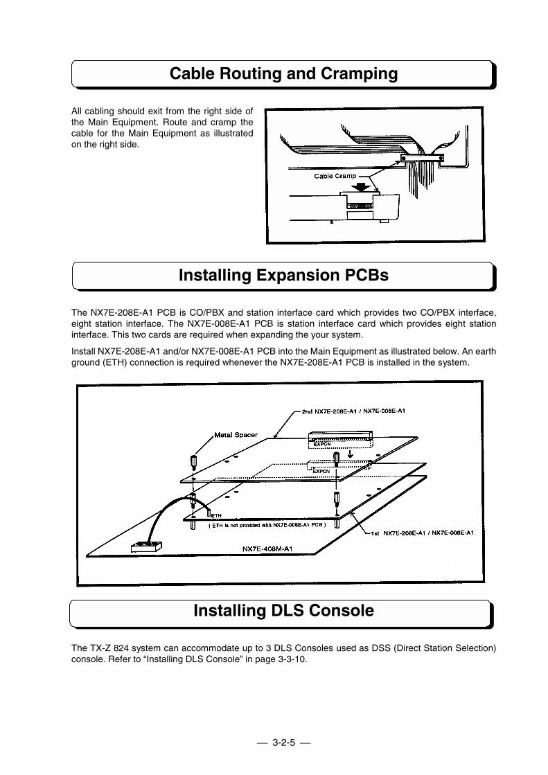
Cable Routing and Cramping
All cabling should exit from the right side ofthe Main Equipment. Route and cramp thecable for the Main Equipment as illustratedon the right side.
Installing Expansion PCBs
The NX7E-208E-A1 PCB is CO/PBX and station interface card which provides two CO/PBX interface,eight station interface. The NX7E-008E-A1 PCB is station interface card which provides eight stationinterface. This two cards are required when expanding the your system.
Install NX7E-208E-A1 and/or NX7E-008E-A1 PCB into the Main Equipment as illustrated below. An earthground (ETH) connection is required whenever the NX7E-208E-A1 PCB is installed in the system.
Installing DLS Console
The TX-Z 824 system can accommodate up to 3 DLS Consoles used as DSS (Direct Station Selection)console. Refer to “Installing DLS Console” in page 3-3-10.
3-2-6
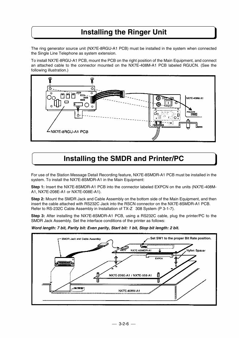
Installing the Ringer Unit
The ring generator source unit (NX7E-8RGU-A1 PCB) must be installed in the system when connectedthe Single Line Telephone as system extension.
To install NX7E-8RGU-A1 PCB, mount the PCB on the right position of the Main Equipment, and connectan attached cable to the connector mounted on the NX7E-408M-A1 PCB labeled RGUCN. (See thefollowing illustration.)
Installing the SMDR and Printer/PC
For use of the Station Message Detail Recording feature, NX7E-8SMDR-A1 PCB must be installed in thesystem. To install the NX7E-8SMDR-A1 in the Main Equipment:
Step 1: Insert the NX7E-8SMDR-A1 PCB into the connector labeled EXPCN on the units (NX7E-408M-A1, NX7E-208E-A1 or NX7E-008E-A1).
Step 2: Mount the SMDR Jack and Cable Assembly on the bottom side of the Main Equipment, and theninsert the cable attached with RS232C Jack into the RSCN connector on the NX7E-8SMDR-A1 PCB.Refer to RS-232C Cable Assembly in Installation of TX-Z 308 System (P 3-1-7).
Step 3: After installing the NX7E-8SMDR-A1 PCB, using a RS232C cable, plug the printer/PC to theSMDR Jack Assembly. Set the interface conditions of the printer as follows:
Word length: 7 bit, Parity bit: Even parity, Start bit: 1 bit, Stop bit length: 2 bit.
Set SW1 to the proper Bit Rate position.
3-2-7
Installing 4PFU-A1 PCB
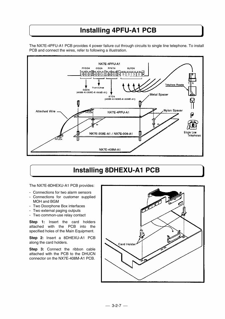
The NX7E-4PFU-A1 PCB provides 4 power failure cut through circuits to single line telephone. To installPCB and connect the wires, refer to following a illustration.
Installing 8DHEXU-A1 PCB
The NX7E-8DHEXU-A1 PCB provides:
- Connections for two alarm sensors- Connections for customer supplied
MOH and BGM- Two Doorphone Box interfaces- Two external paging outputs- Two common-use relay contact
Step 1: Insert the card holdersattached with the PCB into thespecified holes of the Main Equipment.
Step 2: Insert a 8DHEXU-A1 PCBalong the card holders.
Step 3: Connect the ribbon cableattached with the PCB to the DHUCNconnector on the NX7E-408M-A1 PCB.
3-2-8
Installing the Doorphone Box
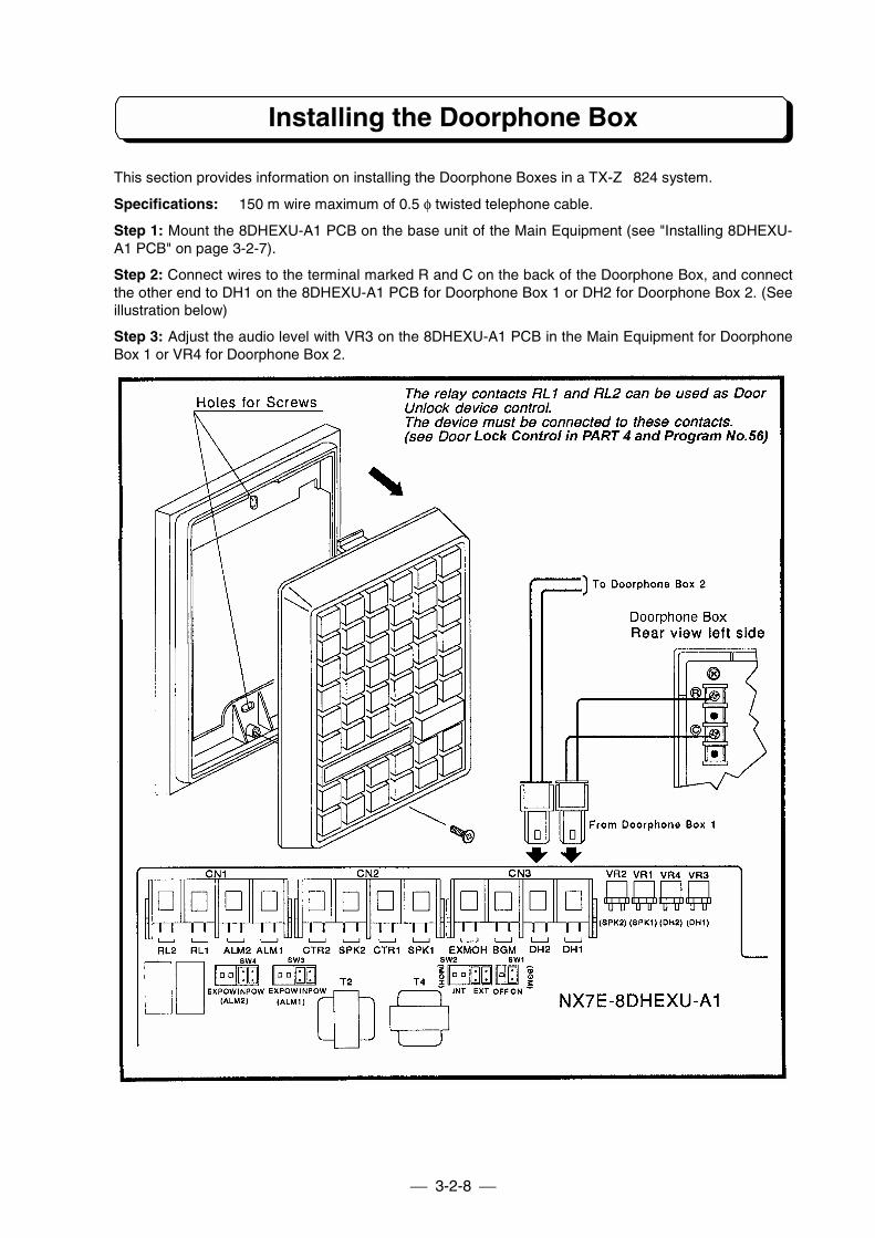
This section provides information on installing the Doorphone Boxes in a TX-Z 824 system.
Specifications: 150 m wire maximum of 0.5 φ twisted telephone cable.
Step 1: Mount the 8DHEXU-A1 PCB on the base unit of the Main Equipment (see "Installing 8DHEXU-A1 PCB" on page 3-2-7).
Step 2: Connect wires to the terminal marked R and C on the back of the Doorphone Box, and connectthe other end to DH1 on the 8DHEXU-A1 PCB for Doorphone Box 1 or DH2 for Doorphone Box 2. (Seeillustration below)
Step 3: Adjust the audio level with VR3 on the 8DHEXU-A1 PCB in the Main Equipment for DoorphoneBox 1 or VR4 for Doorphone Box 2.
3-2-9
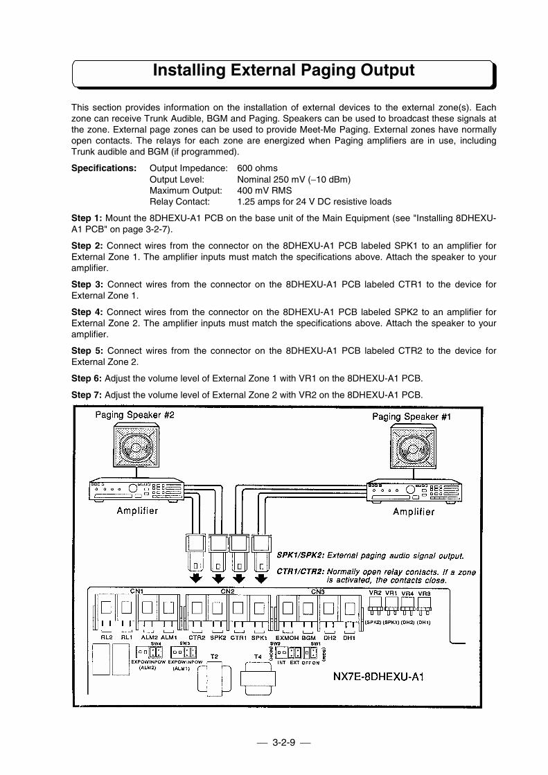
Installing External Paging Output
This section provides information on the installation of external devices to the external zone(s). Eachzone can receive Trunk Audible, BGM and Paging. Speakers can be used to broadcast these signals atthe zone. External page zones can be used to provide Meet-Me Paging. External zones have normallyopen contacts. The relays for each zone are energized when Paging amplifiers are in use, includingTrunk audible and BGM (if programmed).
Specifications: Output Impedance: 600 ohmsOutput Level: Nominal 250 mV (−10 dBm)Maximum Output: 400 mV RMSRelay Contact: 1.25 amps for 24 V DC resistive loads
Step 1: Mount the 8DHEXU-A1 PCB on the base unit of the Main Equipment (see "Installing 8DHEXU-A1 PCB" on page 3-2-7).
Step 2: Connect wires from the connector on the 8DHEXU-A1 PCB labeled SPK1 to an amplifier forExternal Zone 1. The amplifier inputs must match the specifications above. Attach the speaker to youramplifier.
Step 3: Connect wires from the connector on the 8DHEXU-A1 PCB labeled CTR1 to the device forExternal Zone 1.
Step 4: Connect wires from the connector on the 8DHEXU-A1 PCB labeled SPK2 to an amplifier forExternal Zone 2. The amplifier inputs must match the specifications above. Attach the speaker to youramplifier.
Step 5: Connect wires from the connector on the 8DHEXU-A1 PCB labeled CTR2 to the device forExternal Zone 2.
Step 6: Adjust the volume level of External Zone 1 with VR1 on the 8DHEXU-A1 PCB.
Step 7: Adjust the volume level of External Zone 2 with VR2 on the 8DHEXU-A1 PCB.
3-2-10
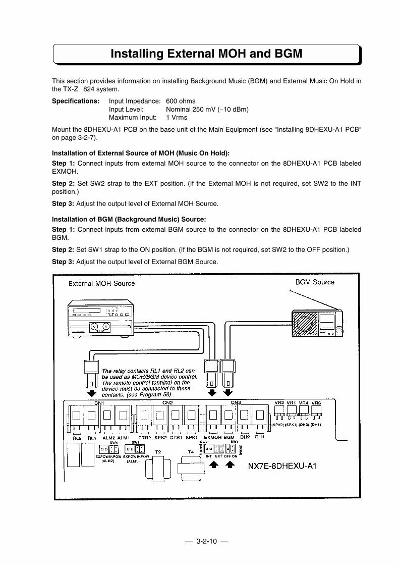
Installing External MOH and BGM
This section provides information on installing Background Music (BGM) and External Music On Hold inthe TX-Z 824 system.
Specifications: Input Impedance: 600 ohmsInput Level: Nominal 250 mV (−10 dBm)Maximum Input: 1 Vrms
Mount the 8DHEXU-A1 PCB on the base unit of the Main Equipment (see "Installing 8DHEXU-A1 PCB"on page 3-2-7).
Installation of External Source of MOH (Music On Hold):
Step 1: Connect inputs from external MOH source to the connector on the 8DHEXU-A1 PCB labeledEXMOH.
Step 2: Set SW2 strap to the EXT position. (If the External MOH is not required, set SW2 to the INTposition.)
Step 3: Adjust the output level of External MOH Source.
Installation of BGM (Background Music) Source:
Step 1: Connect inputs from external BGM source to the connector on the 8DHEXU-A1 PCB labeledBGM.
Step 2: Set SW1 strap to the ON position. (If the BGM is not required, set SW2 to the OFF position.)
Step 3: Adjust the output level of External BGM Source.
3-2-11
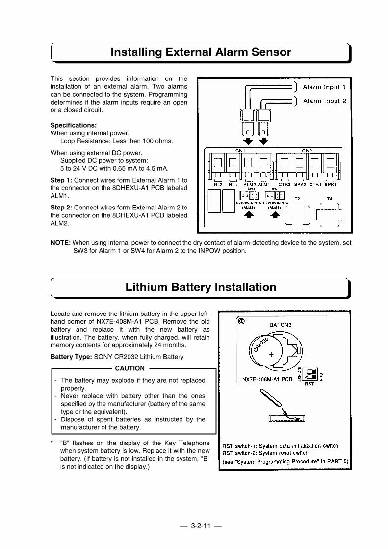
Installing External Alarm Sensor
This section provides information on theinstallation of an external alarm. Two alarmscan be connected to the system. Programmingdetermines if the alarm inputs require an openor a closed circuit.
Specifications:When using internal power.
Loop Resistance: Less then 100 ohms.
When using external DC power.Supplied DC power to system:5 to 24 V DC with 0.65 mA to 4.5 mA.
Step 1: Connect wires form External Alarm 1 tothe connector on the 8DHEXU-A1 PCB labeledALM1.
Step 2: Connect wires form External Alarm 2 tothe connector on the 8DHEXU-A1 PCB labeledALM2.
NOTE: When using internal power to connect the dry contact of alarm-detecting device to the system, setSW3 for Alarm 1 or SW4 for Alarm 2 to the INPOW position.
Lithium Battery Installation
Locate and remove the lithium battery in the upper left-hand corner of NX7E-408M-A1 PCB. Remove the oldbattery and replace it with the new battery asillustration. The battery, when fully charged, will retainmemory contents for approximately 24 months.
Battery Type: SONY CR2032 Lithium Battery
CAUTION
- The battery may explode if they are not replacedproperly.
- Never replace with battery other than the onesspecified by the manufacturer (battery of the sametype or the equivalent).
- Dispose of spent batteries as instructed by themanufacturer of the battery.
* "B" flashes on the display of the Key Telephonewhen system battery is low. Replace it with the newbattery. (If battery is not installed in the system, "B"is not indicated on the display.)
3-2-12
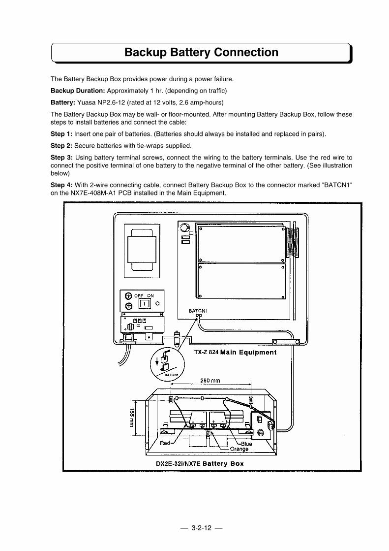
Backup Battery Connection
The Battery Backup Box provides power during a power failure.
Backup Duration: Approximately 1 hr. (depending on traffic)
Battery: Yuasa NP2.6-12 (rated at 12 volts, 2.6 amp-hours)
The Battery Backup Box may be wall- or floor-mounted. After mounting Battery Backup Box, follow thesesteps to install batteries and connect the cable:
Step 1: Insert one pair of batteries. (Batteries should always be installed and replaced in pairs).
Step 2: Secure batteries with tie-wraps supplied.
Step 3: Using battery terminal screws, connect the wiring to the battery terminals. Use the red wire toconnect the positive terminal of one battery to the negative terminal of the other battery. (See illustrationbelow)
Step 4: With 2-wire connecting cable, connect Battery Backup Box to the connector marked "BATCN1"on the NX7E-408M-A1 PCB installed in the Main Equipment.
PART3-3
INSTALLATION OFTX-Z 1232/2464 SYSTEM
Table of Contents
Installing the TX-Z 2464 Main Equipment.....................................................3-3-1The Card Locations of TX-Z 2464 ME ..........................................................3-3-2TX-Z 2464 ME Grounding Requirements .....................................................3-3-3Trunk Line Connection ..................................................................................3-3-3Extension Connection ...................................................................................3-3-4Cable Routing and Cramping........................................................................3-3-6Installing the Expansion Mother Board .........................................................3-3-6Installing the Expansion Power Supply Unit .................................................3-3-7Installing the Ringer Unit ...............................................................................3-3-7Installing 24DHU-A1 PCB .............................................................................3-3-8Installing NX7E-12PFU-A1 PCB ...................................................................3-3-9Installing NX7E-24SMDR-A1 PCB and Printer/PC.......................................3-3-9Installing DLS Console ................................................................................3-3-10Installing Optional Equipment .....................................................................3-3-12TX-Z 1232/2464 Backup Battery Connection .............................................3-3-16
Note: Refer to PART 7 for installation of 24SMCID-A1, 8CID Adaptor, and 24VAU-A1.
3-3-1
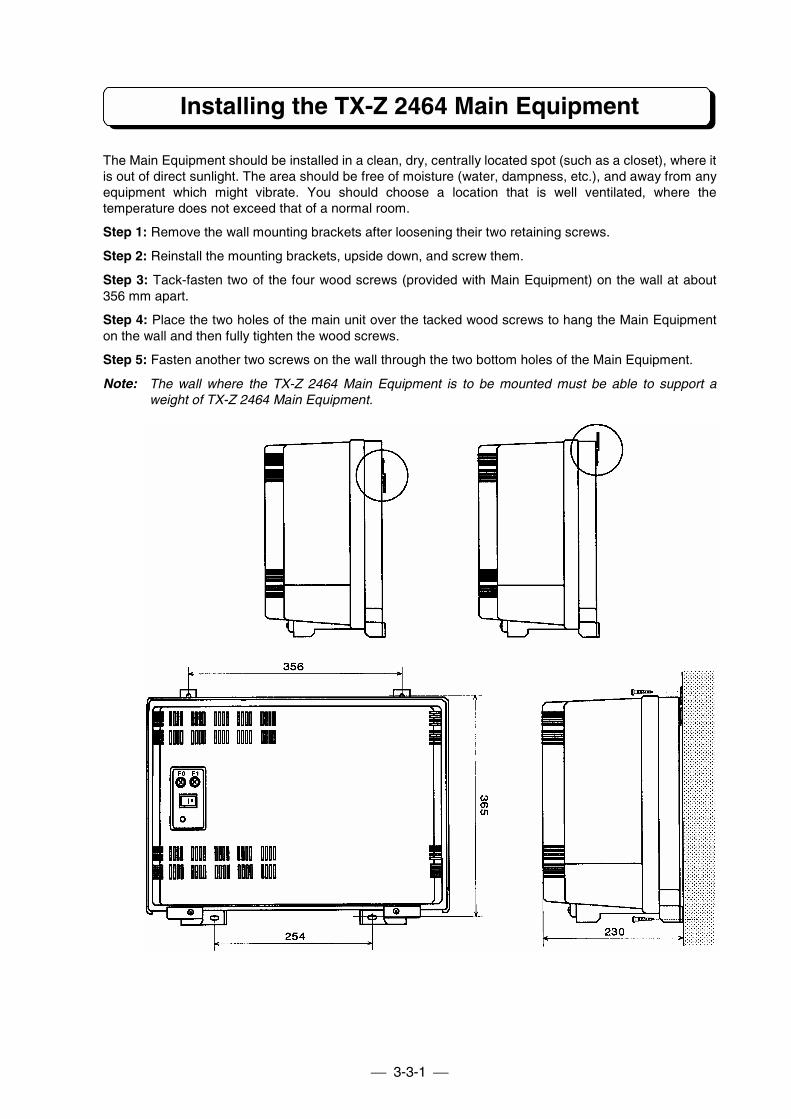
Installing the TX-Z 2464 Main Equipment
The Main Equipment should be installed in a clean, dry, centrally located spot (such as a closet), where itis out of direct sunlight. The area should be free of moisture (water, dampness, etc.), and away from anyequipment which might vibrate. You should choose a location that is well ventilated, where thetemperature does not exceed that of a normal room.
Step 1: Remove the wall mounting brackets after loosening their two retaining screws.
Step 2: Reinstall the mounting brackets, upside down, and screw them.
Step 3: Tack-fasten two of the four wood screws (provided with Main Equipment) on the wall at about356 mm apart.
Step 4: Place the two holes of the main unit over the tacked wood screws to hang the Main Equipmenton the wall and then fully tighten the wood screws.
Step 5: Fasten another two screws on the wall through the two bottom holes of the Main Equipment.
Note: The wall where the TX-Z 2464 Main Equipment is to be mounted must be able to support aweight of TX-Z 2464 Main Equipment.
3-3-2
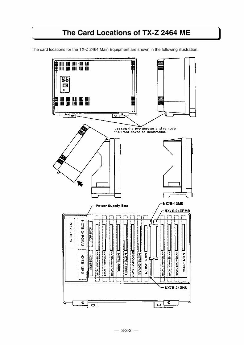
The Card Locations of TX-Z 2464 ME
The card locations for the TX-Z 2464 Main Equipment are shown in the following illustration.
3-3-3
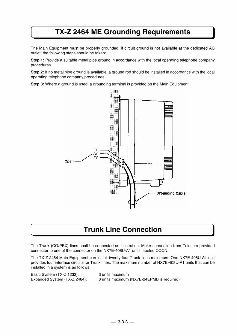
TX-Z 2464 ME Grounding Requirements
The Main Equipment must be properly grounded. If circuit ground is not available at the dedicated ACoutlet, the following steps should be taken:
Step 1: Provide a suitable metal pipe ground in accordance with the local operating telephone companyprocedures.
Step 2: If no metal pipe ground is available, a ground rod should be installed in accordance with the localoperating telephone company procedures.
Step 3: Where a ground is used, a grounding terminal is provided on the Main Equipment.
Trunk Line Connection
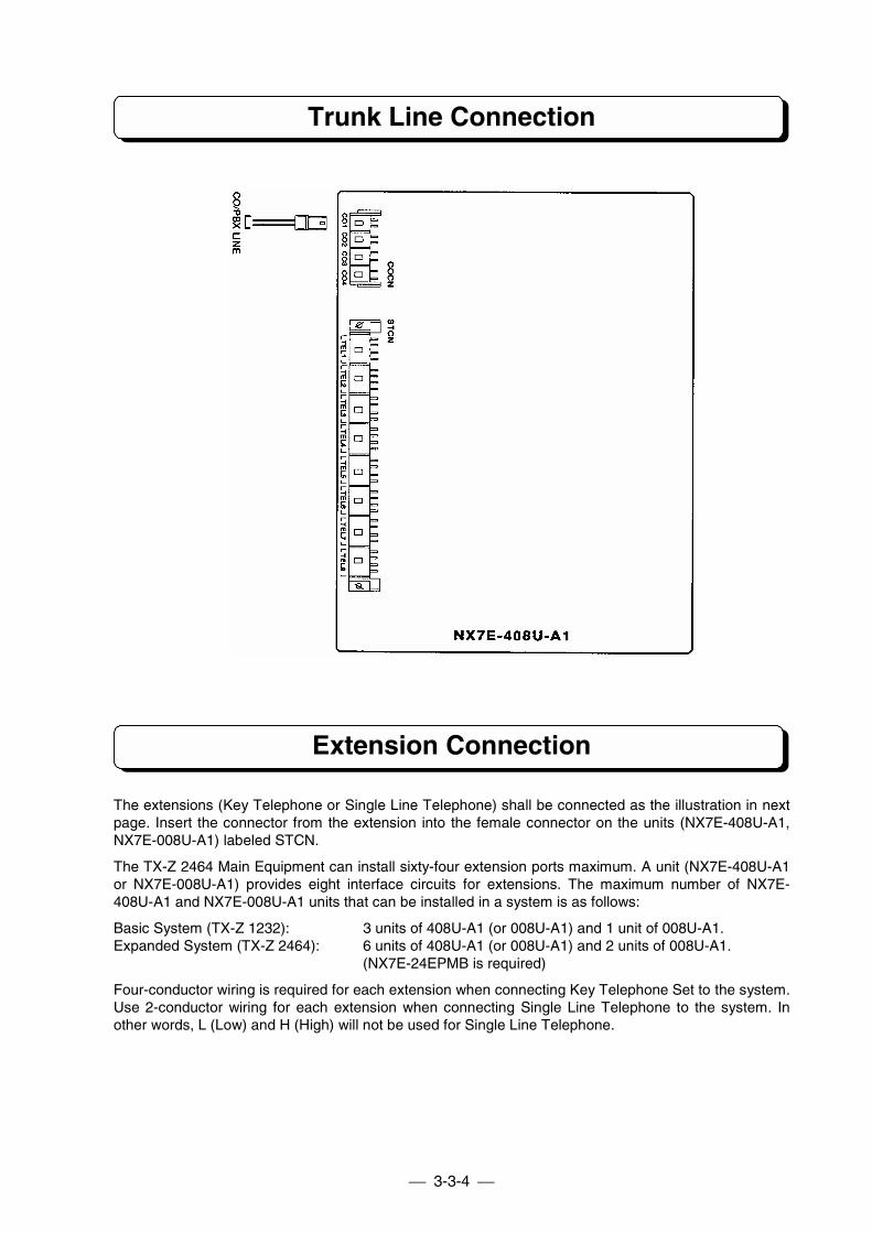
The Trunk (CO/PBX) lines shall be connected as illustration. Make connection from Telecom providedconnector to one of the connector on the NX7E-408U-A1 units labeled COCN.
The TX-Z 2464 Main Equipment can install twenty-four Trunk lines maximum. One NX7E-408U-A1 unitprovides four interface circuits for Trunk lines. The maximum number of NX7E-408U-A1 units that can beinstalled in a system is as follows:
Basic System (TX-Z 1232): 3 units maximumExpanded System (TX-Z 2464): 6 units maximum (NX7E-24EPMB is required)
3-3-4
Trunk Line Connection
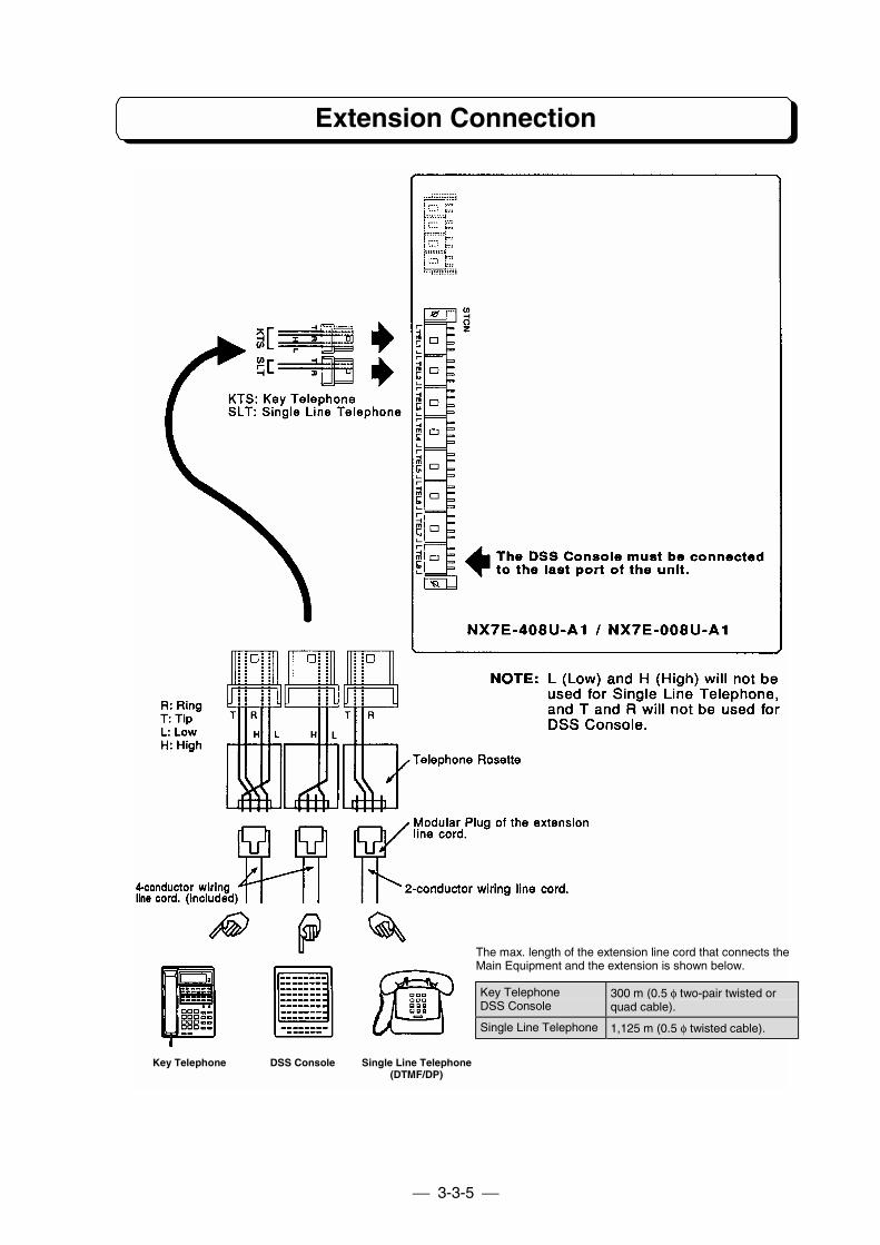
Extension Connection
The extensions (Key Telephone or Single Line Telephone) shall be connected as the illustration in nextpage. Insert the connector from the extension into the female connector on the units (NX7E-408U-A1,NX7E-008U-A1) labeled STCN.
The TX-Z 2464 Main Equipment can install sixty-four extension ports maximum. A unit (NX7E-408U-A1or NX7E-008U-A1) provides eight interface circuits for extensions. The maximum number of NX7E-408U-A1 and NX7E-008U-A1 units that can be installed in a system is as follows:
Basic System (TX-Z 1232): 3 units of 408U-A1 (or 008U-A1) and 1 unit of 008U-A1.Expanded System (TX-Z 2464): 6 units of 408U-A1 (or 008U-A1) and 2 units of 008U-A1.
(NX7E-24EPMB is required)
Four-conductor wiring is required for each extension when connecting Key Telephone Set to the system.Use 2-conductor wiring for each extension when connecting Single Line Telephone to the system. Inother words, L (Low) and H (High) will not be used for Single Line Telephone.
3-3-5
Extension Connection
The max. length of the extension line cord that connects theMain Equipment and the extension is shown below.
Key TelephoneDSS Console
300 m (0.5 φ two-pair twisted orquad cable).
Single Line Telephone 1,125 m (0.5 φ twisted cable).
Key Telephone DSS Console Single Line Telephone(DTMF/DP)
3-3-6
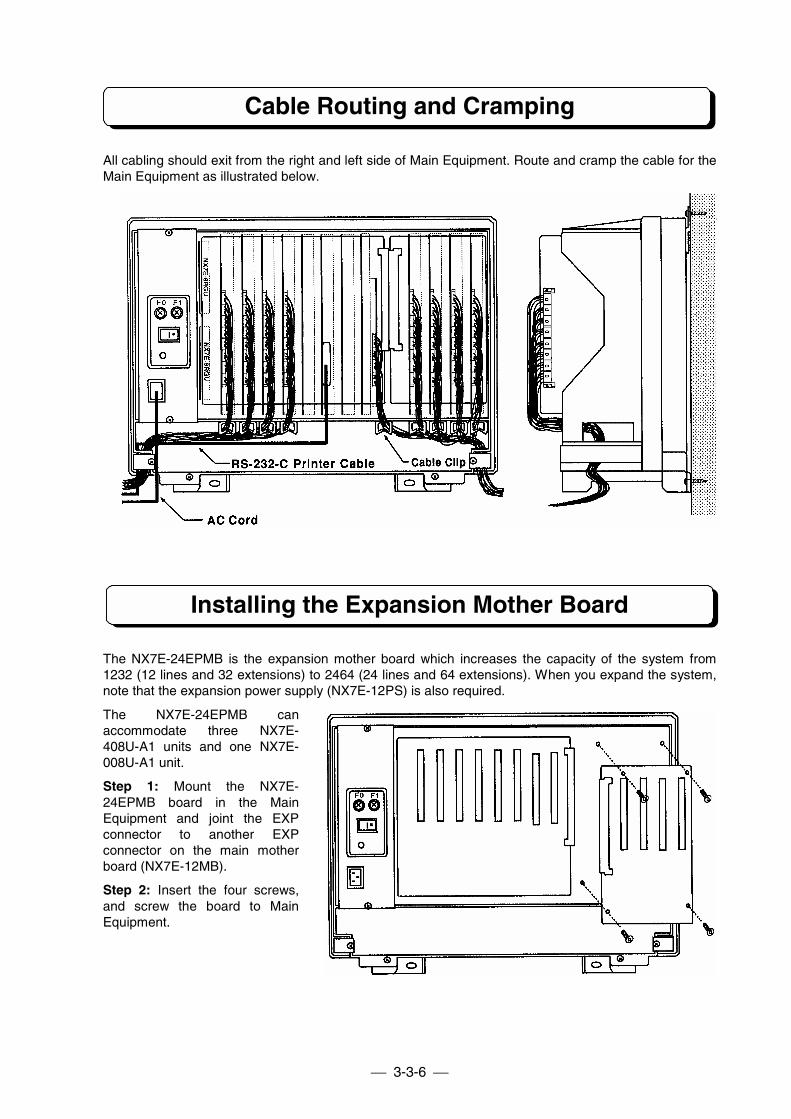
Cable Routing and Cramping
All cabling should exit from the right and left side of Main Equipment. Route and cramp the cable for theMain Equipment as illustrated below.
Installing the Expansion Mother Board
The NX7E-24EPMB is the expansion mother board which increases the capacity of the system from1232 (12 lines and 32 extensions) to 2464 (24 lines and 64 extensions). When you expand the system,note that the expansion power supply (NX7E-12PS) is also required.
The NX7E-24EPMB canaccommodate three NX7E-408U-A1 units and one NX7E-008U-A1 unit.
Step 1: Mount the NX7E-24EPMB board in the MainEquipment and joint the EXPconnector to another EXPconnector on the main motherboard (NX7E-12MB).
Step 2: Insert the four screws,and screw the board to MainEquipment.

3-3-7
Installing the Expansion Power Supply Unit
The NX7E-12PS (Expansion power supply unit) is required when the expansion mother board (NX7E-24EPMB) is installed in the system.
Step 1: Loosen the two screws and pull the Power Supply Box out of the Main Equipment.
Step 2: Loosen the six screws and remove the left side panel.
Step 3: Mount the NX7E-12PS unit on the removed panel, and screw the unit as illustrated below.
Step 4: Connect the cables as illustrated below.
Installing the Ringer Unit
The ring generator source unit (NX7E-8RGU-A1 PCB) must be installed in thesystem when connected the Single LineTelephone as system extension.
The unit connected with RGU1connector is needed for Basic System.When expansion mother board isinstalled, 2nd unit connected with RGU2is required for single line telephone.
To install NX7E-8RGU-A1 PCB, loosenthe two screws and pull the PowerSupply Box out of the Main Equipment,then mount the PCB on the PowerSupply Box, and connect an attachedcable to the connector mounted on theNX7E-24POWU PCB labeled RGU1 orRGU2. (See the following illustration.)
Back side view
To Backup Battery Box
3-3-8
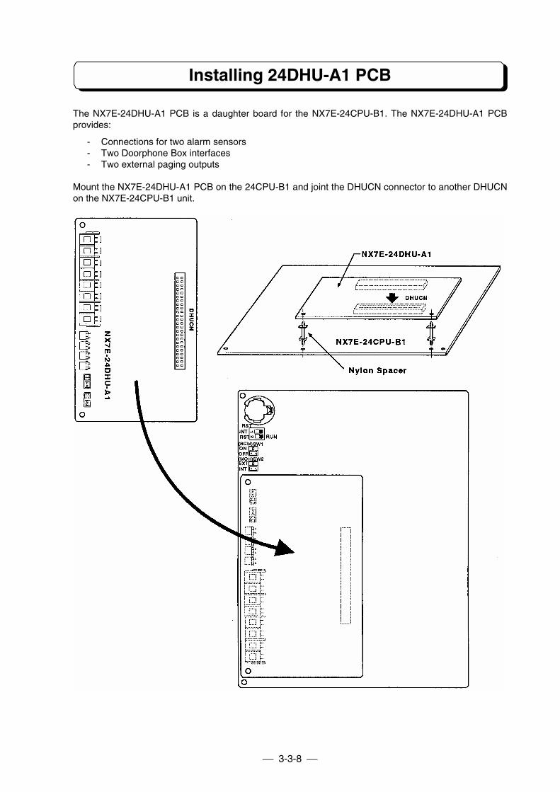
Installing 24DHU-A1 PCB
The NX7E-24DHU-A1 PCB is a daughter board for the NX7E-24CPU-B1. The NX7E-24DHU-A1 PCBprovides:
- Connections for two alarm sensors- Two Doorphone Box interfaces- Two external paging outputs
Mount the NX7E-24DHU-A1 PCB on the 24CPU-B1 and joint the DHUCN connector to another DHUCNon the NX7E-24CPU-B1 unit.
3-3-9
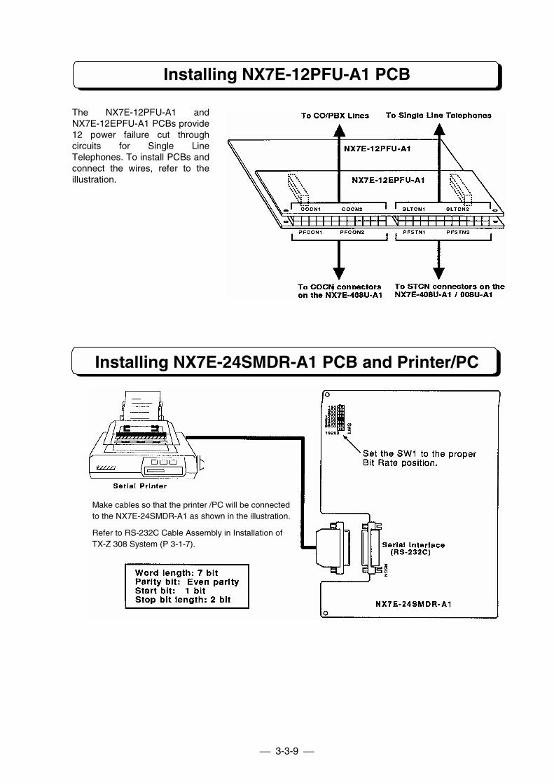
Installing NX7E-12PFU-A1 PCB
The NX7E-12PFU-A1 andNX7E-12EPFU-A1 PCBs provide12 power failure cut throughcircuits for Single LineTelephones. To install PCBs andconnect the wires, refer to theillustration.
Installing NX7E-24SMDR-A1 PCB and Printer/PC
Make cables so that the printer /PC will be connectedto the NX7E-24SMDR-A1 as shown in the illustration.
Refer to RS-232C Cable Assembly in Installation ofTX-Z 308 System (P 3-1-7).
3-3-10
Installing DLS Console
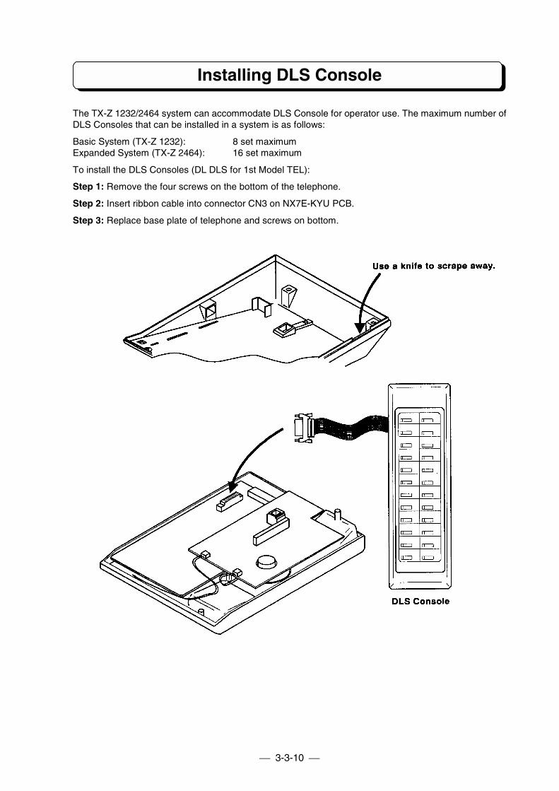
The TX-Z 1232/2464 system can accommodate DLS Console for operator use. The maximum number ofDLS Consoles that can be installed in a system is as follows:
Basic System (TX-Z 1232): 8 set maximumExpanded System (TX-Z 2464): 16 set maximum
To install the DLS Consoles (DL DLS for 1st Model TEL):
Step 1: Remove the four screws on the bottom of the telephone.
Step 2: Insert ribbon cable into connector CN3 on NX7E-KYU PCB.
Step 3: Replace base plate of telephone and screws on bottom.
3-3-11
Installing DLS Console
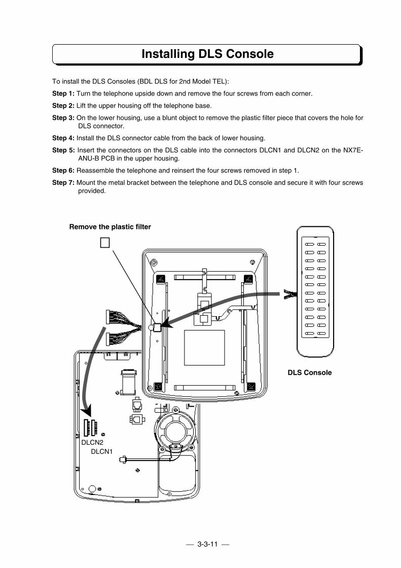
To install the DLS Consoles (BDL DLS for 2nd Model TEL):
Step 1: Turn the telephone upside down and remove the four screws from each corner.
Step 2: Lift the upper housing off the telephone base.
Step 3: On the lower housing, use a blunt object to remove the plastic filter piece that covers the hole forDLS connector.
Step 4: Install the DLS connector cable from the back of lower housing.
Step 5: Insert the connectors on the DLS cable into the connectors DLCN1 and DLCN2 on the NX7E-ANU-B PCB in the upper housing.
Step 6: Reassemble the telephone and reinsert the four screws removed in step 1.
Step 7: Mount the metal bracket between the telephone and DLS console and secure it with four screwsprovided.
DLS Console
DLCN1DLCN2
Remove the plastic filter
3-3-12
Installing Optional Equipment
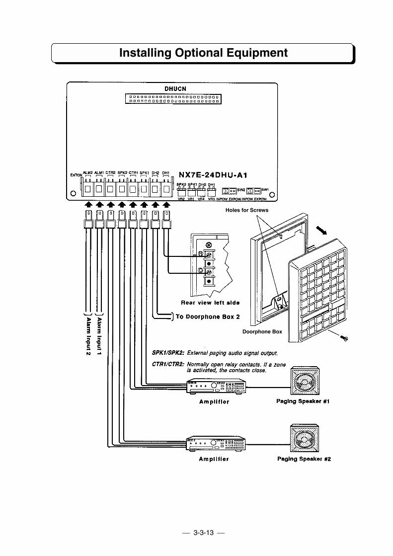
Installing the Doorphone Box:
This section provides information on installing the Doorphone Boxes in TX-Z 1232/2464 system.
Specifications: 150 m wire maximum of 0.5 φ twisted telephone cable.
Step 1: Connect wires to the terminal marked R and C on the back of the Doorphone Box, and connectthe other end to DH1 on the 24DHU-A1 PCB for Doorphone Box 1 or DH2 for Doorphone Box 2.
Step 2: Adjust the audio level with VR3 on the 24DHU-A1 PCB for Doorphone Box 1 or VR4 forDoorphone Box 2.
Installing External Paging Output:
This section provides information for the installation of external devices to the external zone(s). Eachzone can receive Trunk Audible, BGM and Paging. Speakers can be used to broadcast these signals atthe zone. External page zones can be used to provide Meet-Me Paging. External zones have normallyopen contacts. The relays for each zone are energized when Paging amplifiers are in use, includingTrunk audible and BGM (if programmed).
Specifications: Output impedance: 600 ohmsOutput Level: Nominal 250 mV (−10 dBm)Maximum Output: 400 mV RMSRelay Contact: 1.25 amps for 24 V DC resistive loads
Step 1: Connect wires from the connector on the 24DHU-A1 PCB labeled SPK1 to an amplifier forExternal Zone 1, or connector labeled SPK2 to an amplifier for External Zone 2. The amplifier inputs mustmatch the specifications above. Attach the speaker to your amplifier.
Step 2: Connect wires from the connector an the 24DHU-AI PCB labeled CTR 1 to the device forExternal Zone 1, or connector labeled CTR2 to the device for External Zone 2.
Step 3: Adjust the volume level of External Zone 1 with VR1, or adjust the volume level of External Zone2 with VR2 on the 24DHU-AI PCB.
Installing External Alarm Sensor:
This section provides information on the installation of an external alarm. Two alarms can be connectedto the system. Programming determines if the alarm inputs require an open or a closed circuit.
Specifications:When using internal power.
Loop Resistance: Less then 100 ohms.
When using external DC power.Supplied DC power to system:5 to 24 V DC with 0.65 mA to 4.5 mA.
Step 1: Connect wires form External Alarm 1 to the connector on the 24DHU-A1 PCB labeled ALM1.
Step 2: Connect wires form External Alarm 2 to the connector on the 24DHU-AI PCB labeled ALM2.
NOTE: When using internal power to connect the dry contact of alarm-detecting device to the system,set SW1 for Alarm 1 or SW2 for Alarm 2 to the INPOW position.
3-3-13
Installing Optional Equipment
Holes for Screws
Doorphone Box
3-3-14
Installing Optional Equipment
Installing External MOH and BGM:
This section provides information on installing Background Music (BGM) and External Music On Hold inthe TX-Z 1232/2464 system.
Specifications: Input Impedance: 600 ohmsInput Level: Nominal 250 mV (−10 dBm)Maximum Input: 1 Vrms
Installation of External Source of MOH (Music On Hold):
Step 1: Connect inputs from external MOH source to the connector on the 24CPU-B1 PCB labeledEXMOH.
Step 2: Set SW2 strap to the EXT position. (if the External MOH is not required, set SW2 to the INTposition.)
Step 3: Adjust the output level of External MOH Source as the illustration in the next page.
Installation of BGM (Background Music) Source:
Step 1: Connect inputs from external BGM source to the connector on the 24CPU-B1 PCB labeled BGM.
Step 2: Set SW1 strap to the ON position. (If the BGM is not required, set SW2 to the OFF position.)
Step 3: Adjust the output level of External BGM Source as the illustration in the next page.
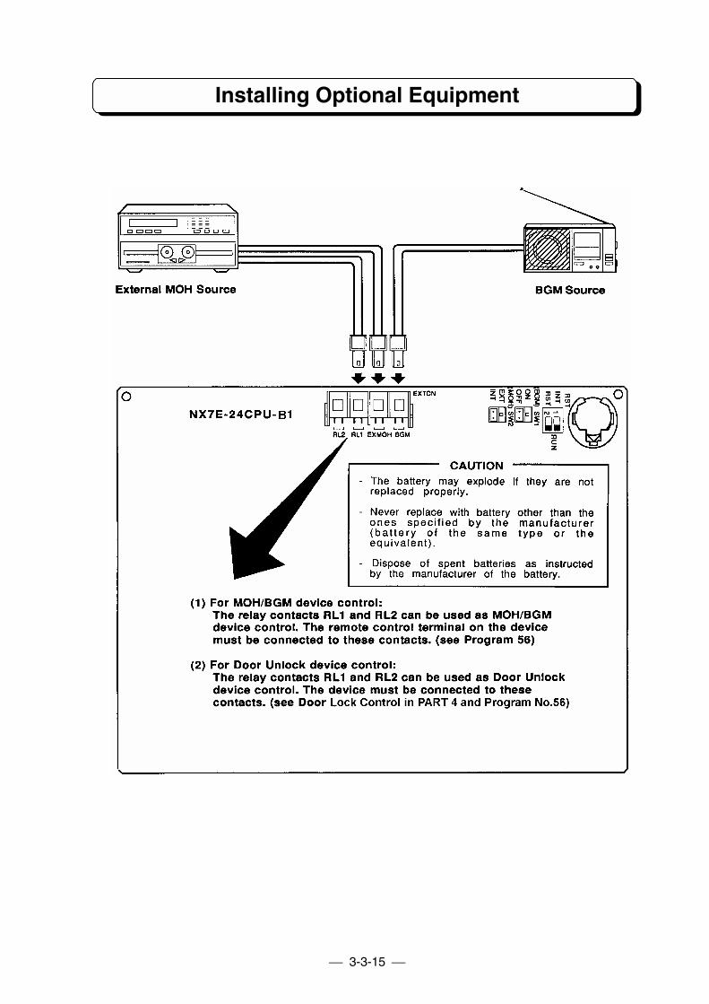
3-3-15
Installing Optional Equipment
3-3-16
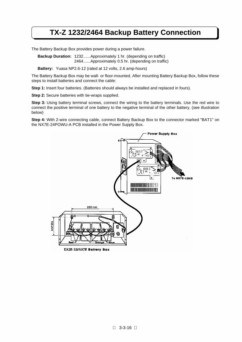
TX-Z 1232/2464 Backup Battery Connection
The Battery Backup Box provides power during a power failure.
Backup Duration: 1232......Approximately 1 hr. (depending on traffic)2464......Approximately 0.5 hr. (depending on traffic)
Battery: Yuasa NP2.6-12 (rated at 12 volts, 2.6 amp-hours)
The Battery Backup Box may be wall- or floor-mounted. After mounting Battery Backup Box, follow thesesteps to install batteries and connect the cable:
Step 1: Insert four batteries. (Batteries should always be installed and replaced in fours).
Step 2: Secure batteries with tie-wraps supplied.
Step 3: Using battery terminal screws, connect the wiring to the battery terminals. Use the red wire toconnect the positive terminal of one battery to the negative terminal of the other battery. (see illustrationbelow)
Step 4: With 2-wire connecting cable, connect Battery Backup Box to the connector marked "BAT1" onthe NX7E-24POWU-A PCB installed in the Power Supply Box.
PART 4
FEATURE DESCRIPTIONAND OPERATION
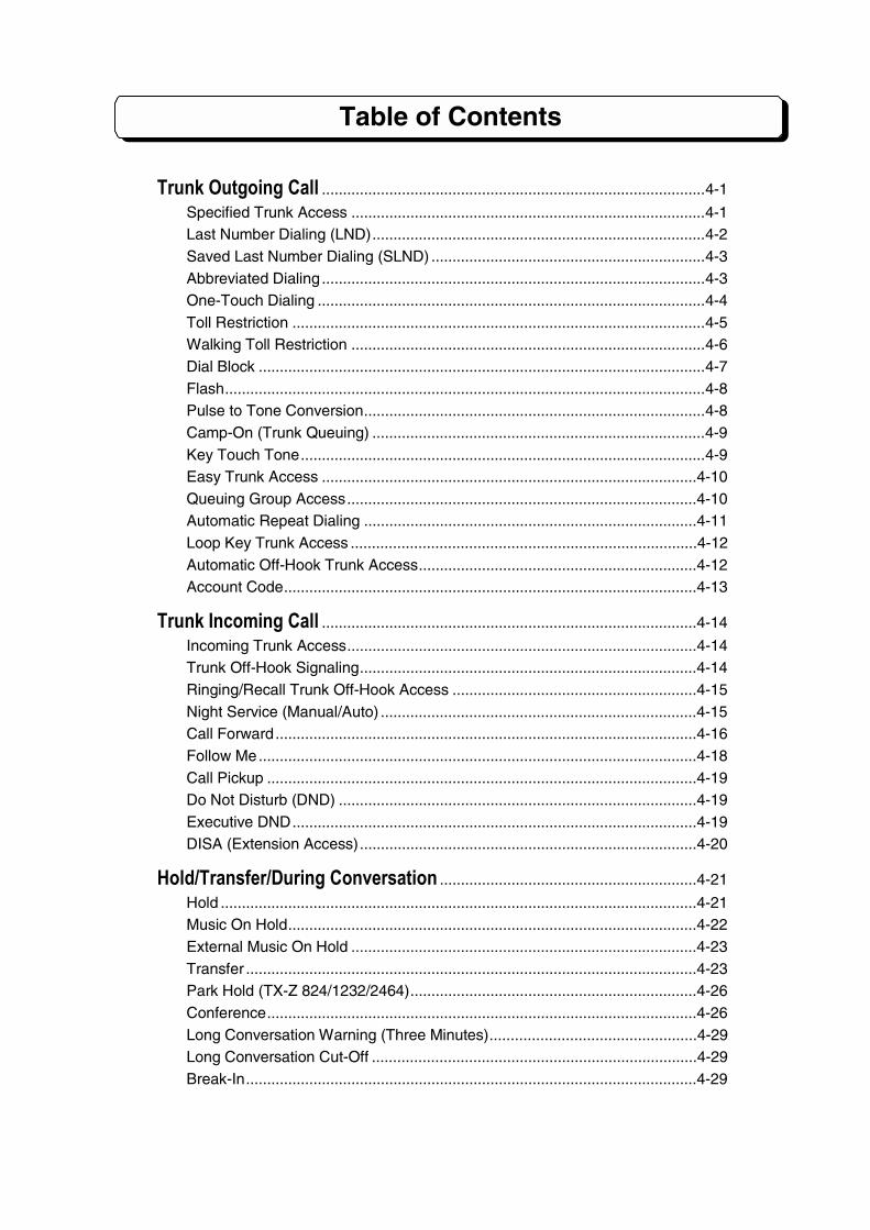
Table of Contents
Trunk Outgoing Call ...........................................................................................4-1
Specified Trunk Access ....................................................................................4-1Last Number Dialing (LND)...............................................................................4-2Saved Last Number Dialing (SLND) .................................................................4-3Abbreviated Dialing...........................................................................................4-3One-Touch Dialing ............................................................................................4-4Toll Restriction ..................................................................................................4-5Walking Toll Restriction ....................................................................................4-6Dial Block ..........................................................................................................4-7Flash..................................................................................................................4-8Pulse to Tone Conversion.................................................................................4-8Camp-On (Trunk Queuing) ...............................................................................4-9Key Touch Tone................................................................................................4-9Easy Trunk Access .........................................................................................4-10Queuing Group Access...................................................................................4-10Automatic Repeat Dialing ...............................................................................4-11Loop Key Trunk Access ..................................................................................4-12Automatic Off-Hook Trunk Access..................................................................4-12Account Code..................................................................................................4-13
Trunk Incoming Call .........................................................................................4-14
Incoming Trunk Access...................................................................................4-14Trunk Off-Hook Signaling................................................................................4-14Ringing/Recall Trunk Off-Hook Access ..........................................................4-15Night Service (Manual/Auto) ...........................................................................4-15Call Forward....................................................................................................4-16Follow Me........................................................................................................4-18Call Pickup ......................................................................................................4-19Do Not Disturb (DND) .....................................................................................4-19Executive DND................................................................................................4-19DISA (Extension Access)................................................................................4-20
Hold/Transfer/During Conversation .............................................................4-21
Hold .................................................................................................................4-21Music On Hold.................................................................................................4-22External Music On Hold ..................................................................................4-23Transfer ...........................................................................................................4-23Park Hold (TX-Z 824/1232/2464)....................................................................4-26Conference......................................................................................................4-26Long Conversation Warning (Three Minutes).................................................4-29Long Conversation Cut-Off .............................................................................4-29Break-In...........................................................................................................4-29
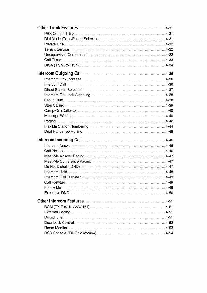
Other Trunk Features .......................................................................................4-31
PBX Compatibility ...........................................................................................4-31Dial Mode (Tone/Pulse) Selection ..................................................................4-31Private Line .....................................................................................................4-32Tenant Service ................................................................................................4-32Unsupervised Conference ..............................................................................4-33Call Timer ........................................................................................................4-33DISA (Trunk-to-Trunk).....................................................................................4-34
Intercom Outgoing Call ...................................................................................4-36
Intercom Link Increase....................................................................................4-36Intercom Call ...................................................................................................4-36Direct Station Selection...................................................................................4-37Intercom Off-Hook Signaling...........................................................................4-38Group Hunt......................................................................................................4-38Step Calling.....................................................................................................4-39Camp-On (Callback) .......................................................................................4-40Message Waiting.............................................................................................4-40Paging .............................................................................................................4-42Flexible Station Numbering.............................................................................4-44Dual Handsfree Hotline...................................................................................4-45
Intercom Incoming Call ...................................................................................4-46
Intercom Answer .............................................................................................4-46Call Pickup ......................................................................................................4-46Meet-Me Answer Paging.................................................................................4-47Meet-Me Conference Paging..........................................................................4-47Do Not Disturb (DND) .....................................................................................4-47Intercom Hold..................................................................................................4-48Intercom Call Transfer.....................................................................................4-49Call Forward....................................................................................................4-49Follow Me........................................................................................................4-49Executive DND................................................................................................4-50
Other Intercom Features .................................................................................4-51
BGM (TX-Z 824/1232/2464) ...........................................................................4-51External Paging...............................................................................................4-51Doorphone.......................................................................................................4-51Door Lock Control ...........................................................................................4-52Room Monitor..................................................................................................4-53DSS Console (TX-Z 1232/2464).....................................................................4-54
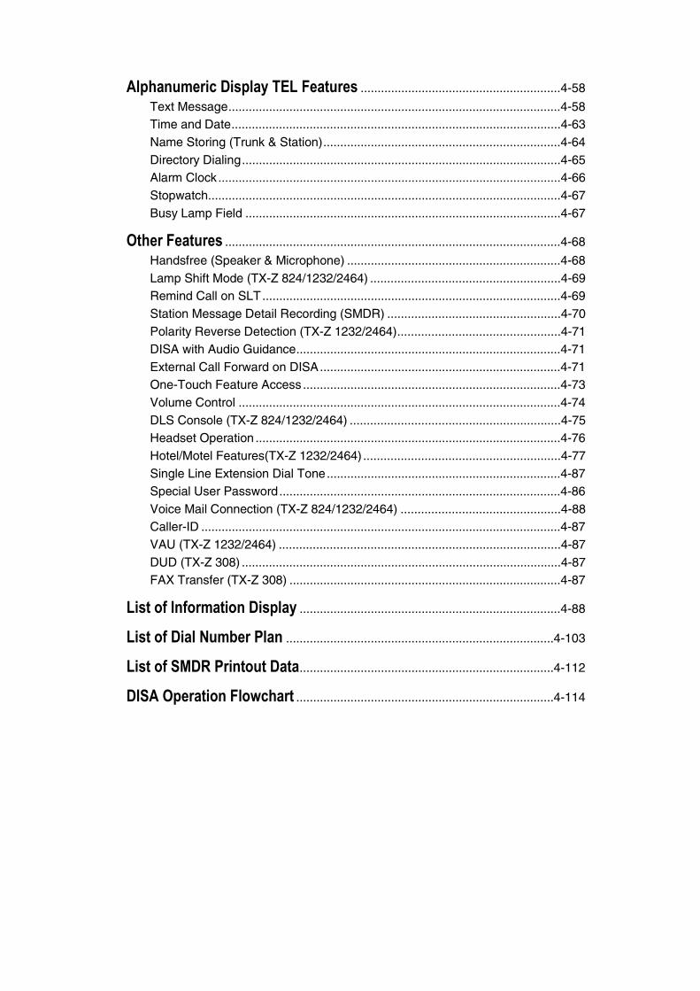
Alphanumeric Display TEL Features ...........................................................4-58
Text Message..................................................................................................4-58Time and Date.................................................................................................4-63Name Storing (Trunk & Station)......................................................................4-64Directory Dialing..............................................................................................4-65Alarm Clock.....................................................................................................4-66Stopwatch........................................................................................................4-67Busy Lamp Field .............................................................................................4-67
Other Features ...................................................................................................4-68
Handsfree (Speaker & Microphone) ...............................................................4-68Lamp Shift Mode (TX-Z 824/1232/2464) ........................................................4-69Remind Call on SLT........................................................................................4-69Station Message Detail Recording (SMDR) ...................................................4-70Polarity Reverse Detection (TX-Z 1232/2464)................................................4-71DISA with Audio Guidance..............................................................................4-71External Call Forward on DISA.......................................................................4-71One-Touch Feature Access ............................................................................4-73Volume Control ...............................................................................................4-74DLS Console (TX-Z 824/1232/2464) ..............................................................4-75Headset Operation ..........................................................................................4-76Hotel/Motel Features(TX-Z 1232/2464) ..........................................................4-77Single Line Extension Dial Tone.....................................................................4-87Special User Password...................................................................................4-86Voice Mail Connection (TX-Z 824/1232/2464) ...............................................4-88Caller-ID ..........................................................................................................4-87VAU (TX-Z 1232/2464) ...................................................................................4-87DUD (TX-Z 308) ..............................................................................................4-87FAX Transfer (TX-Z 308) ................................................................................4-87
List of Information Display .............................................................................4-88
List of Dial Number Plan ...............................................................................4-103
List of SMDR Printout Data...........................................................................4-112
DISA Operation Flowchart ............................................................................4-114
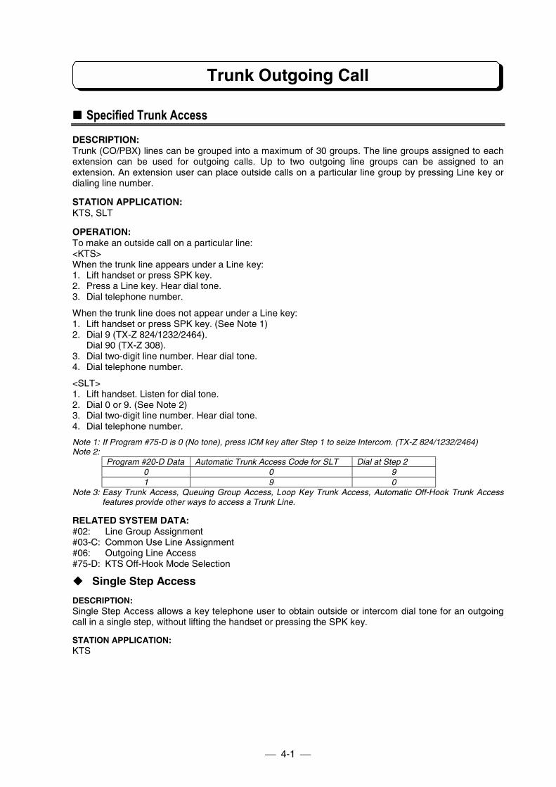
Trunk Outgoing Call
4-1
!!!! Specified Trunk Access
DESCRIPTION:Trunk (CO/PBX) lines can be grouped into a maximum of 30 groups. The line groups assigned to eachextension can be used for outgoing calls. Up to two outgoing line groups can be assigned to anextension. An extension user can place outside calls on a particular line group by pressing Line key ordialing line number.
STATION APPLICATION:KTS, SLT
OPERATION:To make an outside call on a particular line:<KTS>When the trunk line appears under a Line key:1. Lift handset or press SPK key.2. Press a Line key. Hear dial tone.3. Dial telephone number.
When the trunk line does not appear under a Line key:1. Lift handset or press SPK key. (See Note 1)2. Dial 9 (TX-Z 824/1232/2464).
Dial 90 (TX-Z 308).3. Dial two-digit line number. Hear dial tone.4. Dial telephone number.
<SLT>1. Lift handset. Listen for dial tone.2. Dial 0 or 9. (See Note 2)3. Dial two-digit line number. Hear dial tone.4. Dial telephone number.
Note 1: If Program #75-D is 0 (No tone), press ICM key after Step 1 to seize Intercom. (TX-Z 824/1232/2464)Note 2:
Program #20-D Data Automatic Trunk Access Code for SLT Dial at Step 20 0 91 9 0
Note 3: Easy Trunk Access, Queuing Group Access, Loop Key Trunk Access, Automatic Off-Hook Trunk Accessfeatures provide other ways to access a Trunk Line.
RELATED SYSTEM DATA:#02: Line Group Assignment#03-C: Common Use Line Assignment#06: Outgoing Line Access#75-D: KTS Off-Hook Mode Selection
" Single Step Access
DESCRIPTION:Single Step Access allows a key telephone user to obtain outside or intercom dial tone for an outgoingcall in a single step, without lifting the handset or pressing the SPK key.
STATION APPLICATION:KTS
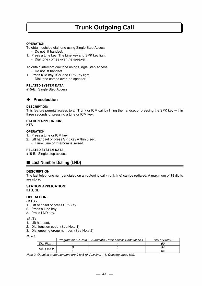
Trunk Outgoing Call
4-2
OPERATION:To obtain outside dial tone using Single Step Access:
- Do not lift handset.1. Press a Line key. The Line key and SPK key light.
- Dial tone comes over the speaker.
To obtain intercom dial tone using Single Step Access:- Do not lift handset.
1. Press ICM key. ICM and SPK key light.- Dial tone comes over the speaker.
RELATED SYSTEM DATA:#15-E: Single Step Access
" Preselection
DESCRIPTION:This feature permits access to an Trunk or ICM call by lifting the handset or pressing the SPK key withinthree seconds of pressing a Line or ICM key.
STATION APPLICATION:KTS
OPERATION:1. Press a Line or ICM key.2. Lift handset or press SPK key within 3 sec.
- Trunk Line or Intercom is seized.
RELATED SYSTEM DATA:#15-E: Single step access
!!!! Last Number Dialing (LND)
DESCRIPTION:The last telephone number dialed on an outgoing call (trunk line) can be redialed. A maximum of 18 digitsare stored.
STATION APPLICATION:KTS, SLT
OPERATION:<KTS>1. Lift handset or press SPK key.2. Press a Line key.3. Press LND key.
<SLT>1. Lift handset.2. Dial function code. (See Note 1)3. Dial queuing group number. (See Note 2)
Note 1:Program #20-D Data Automatic Trunk Access Code for SLT Dial at Step 2
Dial Plan 1 - - 600 0 94
Dial Plan 21 9 04
Note 2: Queuing group numbers are 0 to 6 (0: Any line, 1-6: Queuing group No).
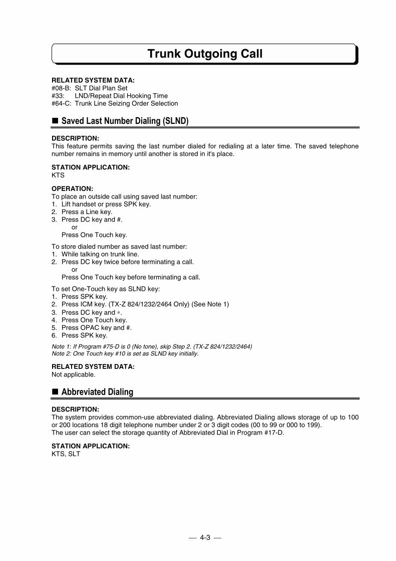
Trunk Outgoing Call
4-3
RELATED SYSTEM DATA:#08-B: SLT Dial Plan Set#33: LND/Repeat Dial Hooking Time#64-C: Trunk Line Seizing Order Selection
!!!! Saved Last Number Dialing (SLND)
DESCRIPTION:This feature permits saving the last number dialed for redialing at a later time. The saved telephonenumber remains in memory until another is stored in it's place.
STATION APPLICATION:KTS
OPERATION:To place an outside call using saved last number:1. Lift handset or press SPK key.2. Press a Line key.3. Press DC key and #.
orPress One Touch key.
To store dialed number as saved last number:1. While talking on trunk line.2. Press DC key twice before terminating a call.
orPress One Touch key before terminating a call.
To set One-Touch key as SLND key:1. Press SPK key.2. Press ICM key. (TX-Z 824/1232/2464 Only) (See Note 1)3. Press DC key and ∗.4. Press One Touch key.5. Press OPAC key and #.6. Press SPK key.
Note 1: If Program #75-D is 0 (No tone), skip Step 2. (TX-Z 824/1232/2464)Note 2: One Touch key #10 is set as SLND key initially.
RELATED SYSTEM DATA:Not applicable.
!!!! Abbreviated Dialing
DESCRIPTION:The system provides common-use abbreviated dialing. Abbreviated Dialing allows storage of up to 100or 200 locations 18 digit telephone number under 2 or 3 digit codes (00 to 99 or 000 to 199).The user can select the storage quantity of Abbreviated Dial in Program #17-D.
STATION APPLICATION:KTS, SLT
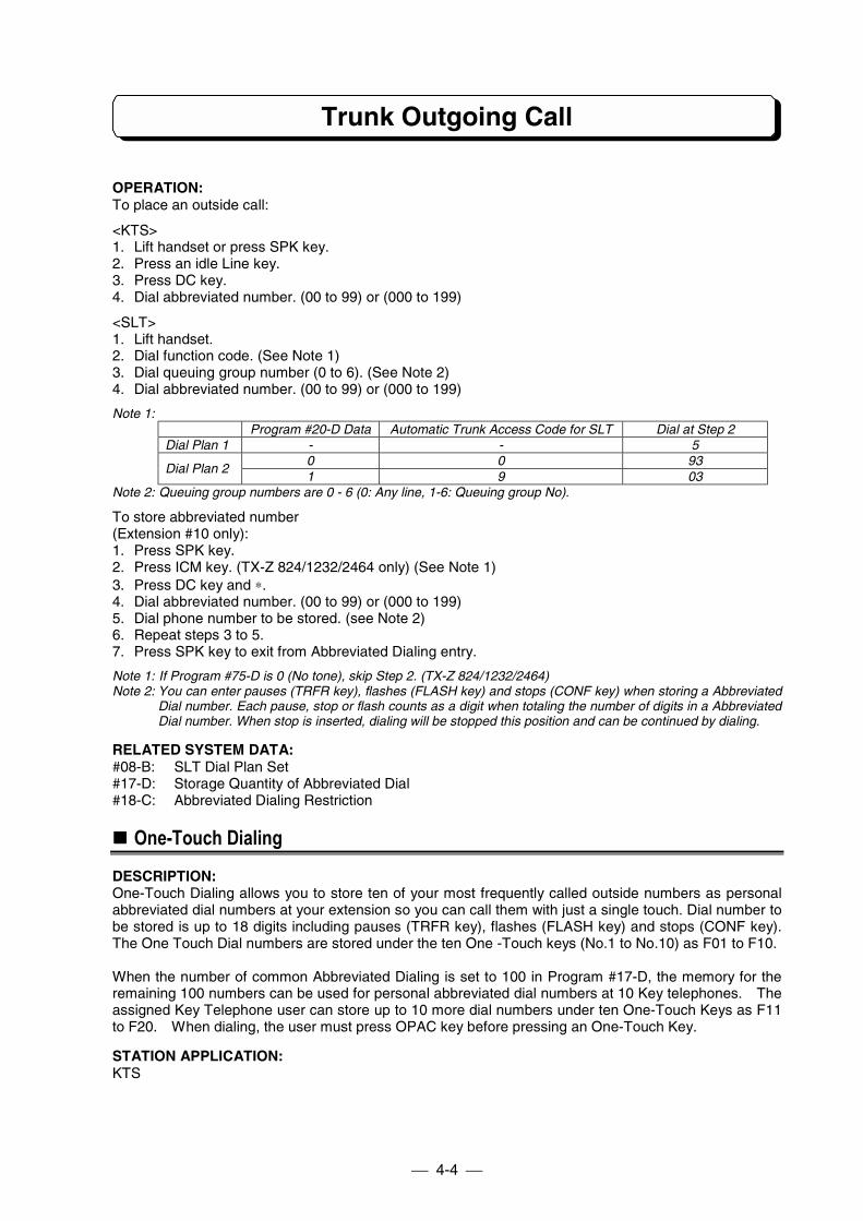
Trunk Outgoing Call
4-4
OPERATION:To place an outside call:
<KTS>1. Lift handset or press SPK key.2. Press an idle Line key.3. Press DC key.4. Dial abbreviated number. (00 to 99) or (000 to 199)
<SLT>1. Lift handset.2. Dial function code. (See Note 1)3. Dial queuing group number (0 to 6). (See Note 2)4. Dial abbreviated number. (00 to 99) or (000 to 199)
Note 1:Program #20-D Data Automatic Trunk Access Code for SLT Dial at Step 2
Dial Plan 1 - - 50 0 93
Dial Plan 21 9 03
Note 2: Queuing group numbers are 0 - 6 (0: Any line, 1-6: Queuing group No).
To store abbreviated number(Extension #10 only):1. Press SPK key.2. Press ICM key. (TX-Z 824/1232/2464 only) (See Note 1)3. Press DC key and ∗.4. Dial abbreviated number. (00 to 99) or (000 to 199)5. Dial phone number to be stored. (see Note 2)6. Repeat steps 3 to 5.7. Press SPK key to exit from Abbreviated Dialing entry.
Note 1: If Program #75-D is 0 (No tone), skip Step 2. (TX-Z 824/1232/2464)Note 2: You can enter pauses (TRFR key), flashes (FLASH key) and stops (CONF key) when storing a Abbreviated
Dial number. Each pause, stop or flash counts as a digit when totaling the number of digits in a AbbreviatedDial number. When stop is inserted, dialing will be stopped this position and can be continued by dialing.
RELATED SYSTEM DATA:#08-B: SLT Dial Plan Set#17-D: Storage Quantity of Abbreviated Dial#18-C: Abbreviated Dialing Restriction
!!!! One-Touch Dialing
DESCRIPTION:One-Touch Dialing allows you to store ten of your most frequently called outside numbers as personalabbreviated dial numbers at your extension so you can call them with just a single touch. Dial number tobe stored is up to 18 digits including pauses (TRFR key), flashes (FLASH key) and stops (CONF key).The One Touch Dial numbers are stored under the ten One -Touch keys (No.1 to No.10) as F01 to F10.
When the number of common Abbreviated Dialing is set to 100 in Program #17-D, the memory for theremaining 100 numbers can be used for personal abbreviated dial numbers at 10 Key telephones. Theassigned Key Telephone user can store up to 10 more dial numbers under ten One-Touch Keys as F11to F20. When dialing, the user must press OPAC key before pressing an One-Touch Key.
STATION APPLICATION:KTS
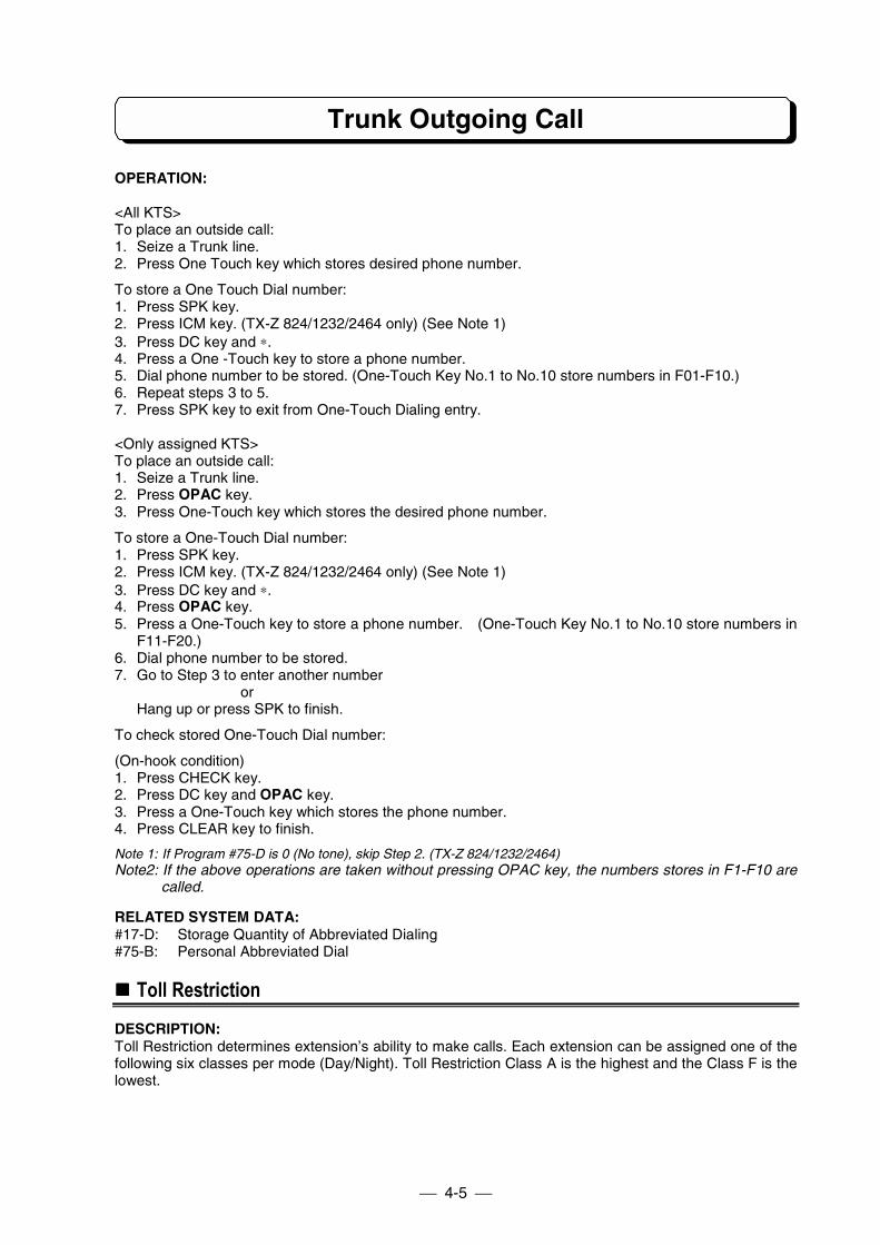
Trunk Outgoing Call
4-5
OPERATION:
<All KTS>To place an outside call:1. Seize a Trunk line.2. Press One Touch key which stores desired phone number.
To store a One Touch Dial number:1. Press SPK key.2. Press ICM key. (TX-Z 824/1232/2464 only) (See Note 1)3. Press DC key and ∗.4. Press a One -Touch key to store a phone number.5. Dial phone number to be stored. (One-Touch Key No.1 to No.10 store numbers in F01-F10.)6. Repeat steps 3 to 5.7. Press SPK key to exit from One-Touch Dialing entry.
<Only assigned KTS>To place an outside call:1. Seize a Trunk line.2. Press OPAC key.3. Press One-Touch key which stores the desired phone number.
To store a One-Touch Dial number:1. Press SPK key.2. Press ICM key. (TX-Z 824/1232/2464 only) (See Note 1)3. Press DC key and ∗.4. Press OPAC key.5. Press a One-Touch key to store a phone number. (One-Touch Key No.1 to No.10 store numbers in
F11-F20.)6. Dial phone number to be stored.7. Go to Step 3 to enter another number
orHang up or press SPK to finish.
To check stored One-Touch Dial number:
(On-hook condition)1. Press CHECK key.2. Press DC key and OPAC key.3. Press a One-Touch key which stores the phone number.4. Press CLEAR key to finish.
Note 1: If Program #75-D is 0 (No tone), skip Step 2. (TX-Z 824/1232/2464)Note2: If the above operations are taken without pressing OPAC key, the numbers stores in F1-F10 are
called.
RELATED SYSTEM DATA:#17-D: Storage Quantity of Abbreviated Dialing#75-B: Personal Abbreviated Dial
!!!! Toll Restriction
DESCRIPTION:Toll Restriction determines extension’s ability to make calls. Each extension can be assigned one of thefollowing six classes per mode (Day/Night). Toll Restriction Class A is the highest and the Class F is thelowest.
Trunk Outgoing Call
4-6
Class-A: No dialing restrictions.Class-B: Dials are restricted by DATA-B except dials matching PBX extension call or DATA-F.Class-C: Dials are restricted by DATA-D2 except dials matching PBX extension call, DATA-C, or DATA-
F.Class-D: Dials are restricted by DATA-D2 or DATA-D1 except dials matching PBX extension call or
DATA-F.Class-E: Dials are restricted all outgoing Trunk calls except dials matching PBX extension call or DATA-
F.Class-F: Intercom calls only.
The DATA (restricted/permitted codes and number length limit) within the Classes must be entered inprogramming.
If there are PBX lines, PBX access code must be assigned in programming in order for Toll Restriction tobe properly applied.
Toll restrictions are not applied to lines programmed as Unrestricted Lines.
When the system is placed in night mode by Night Service feature, the Toll Restriction class assignmentfor night mode is activated.
STATION APPLICATION:KTS, SLT
OPERATION:When an extension user dials a call that is not allowed by the assigned Class, the system automaticallydisconnects the line.
RELATED SYSTEM DATA:#03-D: Unrestricted Lines#18-C: Abbreviated Dialing Restriction#35-A: Toll Restriction Class (Day)#35-B: Toll Restriction Class (Night)#36: Permitted Codes (DATA-C)#37: Number Length Limit (DATA-D1)#38: PBX CO Access Codes (DATA-E)#39: Common Unrestricted Codes (DATA-F)#40: Class-B Restricted Codes (DATA-B)#41: Class-C/D Restricted Codes (DATA-D2)
!!!! Walking Toll Restriction
DESCRIPTION:Walking Toll Restriction lets you temporarily override an extension's dialing restrictions by dialingprogrammed security code at that extension. Dialing the code overrides the restrictions set up in TollRestriction.
STATION APPLICATION:KTS, SLT
OPERATION:<KTS>1. Lift handset.2. Press an idle Line key.3. Press OPAC key.4. Press DC key.5. Dial security code.6. Dial phone number.
Trunk Outgoing Call
4-7
<SLT>1. Lift handset.2. Dial 07 (or 97). => (See Note)3. Dial security code.4. Dial 9 (or 0). => (See Note)5. Dial phone number.
Note:Program #20-D Data Automatic Trunk Access Code for SLT Dial at Step 2 Dial at Step 4
0 0 97 01 9 07 9
RELATED SYSTEM DATA:#42: Walking Toll Restriction Security Code#43: Toll Restriction Class Assignment on Security Code
!!!! Dial Block
DESCRIPTION:Dial Block allows you to temporally lock your extension by entering 4 digit personal code so that otherusers can not make outside calls from your extension. To have this facility each extension has to beassigned by system programming.At No Display Key Telephones, 3-Splash tone is emitted from built-in speaker if somebody tries to makean outside call while Dial Block is set.
STATION APPLICATION:KTS, SLT
OPERATION:To set Dial Block:<KTS>1. Press SPK key.2. Press ICM key. (TX-Z 824/1232/2464 only) (See Note 1)3. Dial ∗, # (TX-Z 824/1232/2464)
Dial 95 (TX-Z 308)4. Dial 4-digit personal code. (See Note 3)5. Dial ∗.
- Confirmation tone when effective.- Error tone when not effective.
6. Press SPK key.
<SLT>1. Lift handset.2. Dial function code. (See Note 2)3. Dial 4-digit personal code. (See Note 3)4. Replace handset.
Note 1: If Program #75-D is 0 (No tone), skip Step 2. (TX-Z 824/1232/2464)Note 2:
Program #20-D Data Automatic Trunk Access Code for SLT Dial at Step 2Dial Plan 1 - - 65
0 0 955Dial Plan 2
1 9 055Note 3: You can dial any number as a personal code.
Trunk Outgoing Call
4-8
To cancel Dial Block:<KTS>1. Press SPK key.2. Press ICM key. (TX-Z 824/1232/2464 only) (See Note 1)3. Dial ∗, # (TX-Z 824/1232/2464).
Dial 95 (TX-Z 308).4. Dial 4-digit code which is entered when setting Dial Block.5. Dial #.
- Confirmation tone when effective.- Error tone when not effective.
6. Press SPK key.
<SLT>1. Lift handset.2. Dial function code. (See Note 2)3. Dial 4-digit personal code which is entered when setting Dial Block.4. Replace handset.
Note 1: If Program #75-D is 0 (No tone), skip Step 2. (TX-Z 824/1232/2464)Note 2:
Program #20-D Data Automatic Trunk Access Code for SLT Dial at Step 2Dial Plan 1 - - 66
0 0 956Dial Plan 2
1 9 056
RELATED SYSTEM DATA:35-C: Toll Restriction Class (Dial Block)
!!!! Flash
DESCRIPTION:The flashing time can be set by system program (#26) to two different timings for CO lines and PBX lines.To send a flashing signal, just depress the FLASH key after seizing a CO/PBX line.
STATION APPLICATION:KTS, SLT
OPERATION:<KTS>1. On the CO/PBX line2. Press FLASH key.
<SLT>(On the CO/PBX line)1. Flash Hookswitch.2. Dial 90.
RELATED SYSTEM DATA:#26: Flash Timer
!!!! Pulse to Tone Conversion
DESCRIPTION:Pulse to Tone Conversion allows you to change from Pulse to Tone dialing mode to access servicessuch as computer-accessed long distance service.
STATION APPLICATION:KTS
Trunk Outgoing Call
4-9
OPERATION:1. Dial phone number. (Pulse mode).2. Dial #.3. Dial phone number. (Tone mode).
RELATED SYSTEM DATA:#01-B: Dial Mode
!!!! Camp-On (Trunk Queuing)
DESCRIPTION:When all trunk lines in a particular Queue Group are busy, Camp-On puts an extension user on a"waiting list" for an available line in the group. As soon as a line becomes free, the user's phone rings anda Line key flashes. Up to eight extension users can activate Camp-On in the same Queue Group. Whensignaled, the user must answer within 20 sec, otherwise the line rings the next extension on the "waitinglist".
STATION APPLICATION:KTS, SLT
OPERATION:To use Camp-On:<KTS>1. Lift handset.2. Press ICM key. (TX-Z 824/1232/2464 only) (See Note)3. Press HOLD key.4. Dial Queuing Group number (0-6) (0: Same group, 1- 6: Group No.).
- If you hear busy tone, the extension can not use Camp-On for that group.5. Replace handset.
<SLT>1. Place an outside call. Hear busy tone.2. Dial Queuing Group number (0-6) (0: Same group, 1- 6: Group No.).3. Replace handset.
Note : If Program #75-D is 0 (No tone), skip Step 2. (TX-Z 824/1232/2464)
When Camp-On rings an extension:<KTS>1. Lift handset.2. Press flashing Line key.
<SLT>1. Lift handset.
RELATED SYSTEM DATA:#01-C: Queuing Group - Line Assignment#16-B: Recall Trunk Off-Hook Access
!!!! Key Touch Tone
DESCRIPTION:The Key Touch Tone feature allows a tone to be emitted from the built-in speaker each time a Line,One-Touch or dial pad key is pressed. The tone confirms the key was fully pressed.
STATION APPLICATION:KTS
Trunk Outgoing Call
4-10
OPERATION:To activate Key Touch Tone:
- Do not lift handset.1. Dial ∗.
To cancel Key Touch Tone:- Do not lift handset.
1. Dial ∗. Final Key Touch Tone is heard.
RELATED SYSTEM DATA:#13-A: Key Touch Tone
!!!! Easy Trunk Access
DESCRIPTION:Easy Trunk Access lets an extension user access an outgoing line without pressing a Line key or dialinga two-digit line number. A single-digit code automatically accesses an outgoing outside line from smallernumber, large number, or rotated number.
STATION APPLICATION:KTS, SLT
OPERATION:To access the first available outgoing line:<KTS>1. (On-Hook and Speaker off condition)2. Dial 0. A line is seized and dial tone comes over the speaker.
<SLT>1. Lift handset.2. Dial 9 or 0. (refer to Program #20-D)
RELATED SYSTEM DATA:#15-C: Automatic Trunk Access#20-D: Automatic Trunk Access Code for SLT#64-C: Trunk Line Seizing Order Selection
!!!! Queuing Group Access
DESCRIPTION:Queuing Group Access lets an extension user access the first available outgoing line in a Queuing Groupwithout pressing a Line key or dialing a two-digit line number. A single-digit code automatically accessesan outgoing outside line from small number, large number, or rotated number.
STATION APPLICATION:KTS, SLT
OPERATION:
To access the first available line in a Queuing Group:<KTS>1. Press SPK key.2. Press ICM key. (TX-Z 824/1232/2464) (See Note)
Dial 91. (TX-Z 308)3. Dial Queuing Group number (1-6). A line is seized and dial tone comes over the speaker.
Trunk Outgoing Call
4-11
<SLT on Dial Plan 1>1. Lift handset.2. Dial Queuing Group number (1-4).
<SLT on Dial Plan 2>1. Lift handset.2. Dial 06 or 96 (refer to #20-D)3. Dial Queuing Group number (1-6)
Note 1: If Program #75-D is 0 (No tone), skip Step 2. (TX-Z 824/1232/2464)
RELATED SYSTEM DATA:#01-C: Queuing Group - Line Assignment#15-C: Automatic Trunk Access#20-D: Automatic Trunk Access Code for SLT#64-C: Trunk Line Seizing Order Selection
!!!! Automatic Repeat Dialing
DESCRIPTION:If an extension user places a trunk call that is busy or unanswered, they can have Automatic RepeatDialing try it again later on. The user doesn't continually have to try the number again -- hoping it will gothrough. Automatic Repeat Dialing automatically retries it until the called party answers. Moreover, whileAutomatic Repeat Dialing is set (waiting, busy or no-answer), Hurry-Up operation can be taken place forimmediate redial.While Automatic Repeat Dialing is set (waiting condition), 2-Splash tone (Mute-tone) is emitted frombuilt-in speaker in 5 sec cycle.
STATION APPLICATION:KTS
OPERATION:To use Automatic Repeat Dialing:1. Place outside call.
- Listen for busy tone or ring-no-answer.2. Press OPAC key.3. Dial 1.4. Replace handset or press SPK key.
- The system periodically redials the call.
To cancel Automatic Repeat Dialing:1. Lifting the handset cancels Automatic Repeat Dialing.
To use Hurry-Up operation1. Press OPAC key.2. Dial 2.
Repeat Dialing and Hurry-Up Operation can be stored under One-touch key.
On TX-Z 308 system, One-Touch Key No.09 is initially set as Automatic Repeat Dial key.
RELATED SYSTEM DATA:#01-C: Queuing Group - Line Assignment#33: LND/Repeat Dial Hooking Time#34: Repeat Dial Timers
Trunk Outgoing Call
4-12
!!!! Loop Key Trunk Access
DESCRIPTION:User can assign only one Loop Key to one of undefined Line keys. The Loop Key should be assigned onan unused Line key in advance by using "One-Touch Feature Access". This feature permits access to anoutgoing line by pressing a Loop Key. The trunk line is seized from small number, large number, orrotated number. This key provides user advantage as follows;
- When the number of Trunk lines connected to the system is larger than the number of Line keys atuser's KTS, user can seize all the Trunk line by pressing the Loop key.
- User can use the Park Hold effectively.
There are 6 types of LED indication.- System Hold: 0.1 sec ON / 0.1 sec OFF (BLF: Green)- Exclusive Hold: 0.1 sec ON / 0.1 sec OFF / 0.1 sec ON / 0.7 sec OFF (BLF: Green)- I-Use: Light (BLF: Green)- Conference standby: 0.1 sec ON / 0.1 sec OFF / 0.1 sec ON / 0.7 sec OFF (BLF: Green)- Idle: Extinguish- All lines are Busy: Light (BLF: Red)
STATION APPLICATION:KTS
OPERATION:To seize a Trunk line:1. Press Loop Key. (Dial Tone is heard.)* Refer to One-Touch Feature Access for how to assign Loop Key.
To answer the incoming call:(This feature is available for KTS which is allowed Ringing Trunk Off-hook Access feature.)1. Incoming call to a Trunk line. (Ringing)
(Loop key is still extinguished.)2. Lift handset. (Loop key lights Green.)
RELATED SYSTEM DATA:#64-C: Trunk Line Seizing Order Selection
!!!! Automatic Off-Hook Trunk Access
DESCRIPTION:The assigned extension users can seize an idle Trunk Line by only lifting handset. The operations suchas pressing Line key or dialing Trunk Access Code become unnecessary. This feature is useful for KeyTelephone users who mainly makes outside calls, or to connect Fax Machines (Modems) instead ofSingle Line Telephones.
STATION APPLICATION:KTS on TX-Z 824/1232/2464, SLT
OPERATION:<KTS>1. Lift handset or press SPK key. (An idle Trunk Line will automatically be seized.)Note 1: If all Trunk Lines are busy, no tone will be heard.Note 2: This disables the user to seize Intercom after lifting handset. Press ICM key before lifting handset to seize
Intercom.Note 3: Lifting handset when the extension is ringing answers Trunk Line or Intercom call.
<SLT>1. Lift handset. (An idle Trunk Line will automatically be seized.)Note : If all Trunk Lines are busy, Busy Tone will be heard.
Trunk Outgoing Call
4-13
Note 2: Assigned SLT user can not place Intercom Calls. However, they can receive incoming Intercom Call andtransferred Trunk Line Call. Transferring Trunk Line calls to another extension is possible.
RELATED SYSTEM DATA:#64-C: Trunk Line Seizing Order Selection#75-C: SLT Automatic Trunk Access#75-D: KTS Off-Hook Mode Selection
!!!! Account Code
DESCRIPTION:Account Code is useful to keep track of expenditures. Extension user dials Account Code before makingoutside call. This code is shown on the SMDR print out.
STATION APPLICATION:KTS, SLT
OPERATION:To enter the Account Code:<KTS>1. Seize an idle Trunk Line. (Hear Dial Tone.)2. Dial ∗.3. Dial Account Code. (Max. 8 digits)4. Dial ∗.5. Dial Telephone Number.
<SLT>1. Seize an idle Trunk Line. (Hear Dial Tone.)2. Flash Hookswitch.3. Dial 99.4. Dial Account Code. (Max. 8 digits)5. Flash Hookswitch.6. Dial Telephone Number.
RELATED SYSTEM DATA:#57-D: KTS Account Code#58-B: SLT Account Code
Trunk Incoming Call
4-14
!!!! Incoming Trunk Access
DESCRIPTION:Trunk lines can be grouped into a maximum of 30 groups. The line groups assigned to each extensioncan access for incoming calls and the audible assignments (day and/or night mode ringing) for theextensions. Up to two incoming line groups can be assigned to an extension. An extension user cananswer an incoming call on a particular line group only if the extension has Incoming Trunk Access tothat group. When an extension is assigned incoming access to a line group, the lines in the group appearunder the Line keys (KTS).
STATION APPLICATION:KTS, SLT
OPERATION:<KTS>To answer an outside call by Direct Pickup:1. Lift handset or press SPK key.2. Press flashing Line key.
To answer an outside call by Dial Pickup:1. Lift handset or press SPK key. (See Note)2. Dial 96 (TX-Z 824/1232/2464).
Dial 92 (TX-Z 308)Note: If Program #75-D is 0 (No tone), press ICM key after Step 1 to seize Intercom. (TX-Z 824/1232/2464)
<SLT on Dial Plan 1>1. Lift handset.2. Dial 06 (or 96). (Refer to #20-D)
<SLT on Dial Plan 2>1. Lift handset.2. Dial 06 or 96. (Refer to #20-D)3. Dial 0.
RELATED SYSTEM DATA:#02: Line Group Assignment#03-C: Common Use Line Assignment#07: Incoming Trunk Access/Audible#16-A: Ringing Trunk Off-Hook Access
!!!! Trunk Off-Hook Signaling
DESCRIPTION:Trunk Off-Hook Signaling provides an extension user with an audible indication of an incoming Trunk callwhile already on a call: the busy extension user hears muted ringing if on a handset call or one shortburst tones (0.5s ON/15s OFF) if on a Handsfree call.
STATION APPLICATION:KTS
OPERATION:To answer a Trunk Off-Hook signal:1. Press HOLD to put an outside call in progress on hold or hang up the call in progress. Intercom calls
must be hung up since they cannot be put on hold.2. Press the flashing Line key.
RELATED SYSTEM DATA:#04-B: Trunk Off-Hook Signaling
Trunk Incoming Call
4-15
!!!! Ringing/Recall Trunk Off-Hook Access
DESCRIPTION:Ringing Trunk Off-Hook Access allows a ringing outside call to be answered by just lifting the handset; aLine key does not have to be pressed. Recall Trunk Off-Hook Access lets a recalling (re-ringing) line beanswered by just lifting the handset.
STATION APPLICATION:KTS, SLT
OPERATION:1. Lift handset.
RELATED SYSTEM DATA:#16-A: Ringing Trunk Off-Hook Access#16-B: Recall Trunk Off-Hook Access
!!!! Night Service (Manual/Auto)
DESCRIPTION:Night Service puts the night audible (ringing) assignment (Program #7) into effect manually orautomatically. Incoming calls on a specific line group will ring at extensions that are assigned nightaudible for that line group. Night Service remains set even if the system power is turned off.
Night Service is available on a system basis or incoming line group basis according to Program #15-B.1. Night audible assignments go into effect at all extensions in the system. Day audible assignments are
ignored. The extension #10 can activate this Night Service (NT) mode unless DSS Console isconnected.On the TX-Z 1232/2464 System, Night Service assignment can be activated by the DSS Console. IfDSS Console is not connected, the extension #10 can activate this mode assignment.
2. Night audible assignments go into effect for the extensions that have the same primary incoming linegroup as the extension that activates this NT mode. Extensions with a different primary incoming linegroup receive ringing according to their day audible assignments. Any extension can activate thismode.This NT mode can be activated by any extension in each same primary incoming line group.
Automatic Mode SwitchingAutomatic Mode Switching (Program #79) allows to switch Day/Night mode according to preprogrammedtime routine for the system. When Automatic Mode Switching places the system in Night Mode, TRFRblinks red at all key telephones. If the system mode is switched manually at No.10 telephone or DSS, itoverrides Automatic Mode Switching assignment.
STATION APPLICATION:KTS, SLT, External speaker, Doorphone
OPERATION:To activate Night Service:<KTS>1. Press SPK key.2. Press ICM key. (TX-Z 824/1232/2464 only) (See Note)3. Press TRFR key.4. Dial #. TRFR lights red.5. Hang up.
Trunk Incoming Call
4-16
To activate Night Service:
<DSS>1. Press NT key. (LED lights red)
To cancel Night Service:
<KTS>1. Press SPK key.2. Press ICM key. (TX-Z 824/1232/2464 only) (See Note)3 Press TRFR key.4. Dial #. TRFR extinguishes.5. Hang up.
To cancel Night Service:
<DSS>1. Press NT key. (LED extinguishes)
This feature can be stored under the One-touch key.
When NT mode 1 is enabled, the TRFR key lights steadily at all KTSs. When NT mode 2 is enabled, the TRFR keylights steadily at the activating extension and at all other KTSs with the same primary incoming line group.
Note: If Program #75-D is 0 (No tone), skip Step 2. (TX-Z 824/1232/2464)
RELATED SYSTEM DATA:#07: Incoming Trunk Access/Audible#15-B: Night Service#79: Automatic Mode Switching Time
!!!! Call Forward
DESCRIPTION:Call Forward reroutes an extension user's incoming outside calls so they ring at a different extension. Anextension user who activates Call Forward does not lose access to incoming calls. Incoming access isshared with the receiving (destination) extension, but only the destination extension rings. There is nolimit in number of extensions which set Call Forward to a same destination. Calls cannot be rerouted toan extension in Do Not Disturb. There are four types of Call Forward:
- Call Forward ImmediateAll calls transferred immediately to the destination.
- Call Forward when BusyCalls are transferred only when the extension is busy.
- Call Forward when UnansweredCalls are transferred only if they are unanswered, and both the destination and the transferringextension ring.
- Call Forward when Busy/UnansweredCalls are transferred only when the extension is busy or unanswered, and both the destination and thetransferring extension ring.
STATION APPLICATION:KTS, SLT
Trunk Incoming Call
4-17
OPERATION:To activate Call Forward:<KTS>1. Press SPK key.2. Press ICM key. (TX-Z 824/1232/2464 only) (See Note 1)3. Press TRFR key.4. Dial destination extension number.5. Dial option code (0-3). (see Note 3)
- One short beep sounds as confirmation.- 3 splash tone means calls cannot be rerouted to that extension. (TX-Z 824/1232/2464)
6. Press SPK key.
<SLT>1. Lift handset.2. Dial function code. (see Note 2)3. Dial destination extension number.4. Dial option code (0-3). (see Note 3)5. Hang up.
Note 1: If Program #75-D is 0 (No tone), skip Step 2. (TX-Z 824/1232/2464)Note 2:
Program #20-D Data Automatic Trunk Access Code for SLT Dial at Step 2Dial Plan 1 - - 63
0 0 953Dial Plan 2
1 9 053Note 3: Option codes are as follows:
0 => Call Forward Immediate1 => Call Forward when Busy2 => Call Forward when Unanswered3 => Call Forward when Busy/Unanswered
To cancel Call Forward (at originating and destination extension):<KTS>1. Press SPK key.2. Press ICM key. (TX-Z 824/1232/2464 only) (See Note 1)3. Press TRFR key twice.4. Press SPK key.
<SLT>1. Lift handset.2. Dial function code. (see Note 2)3. Hang up.
Note 1: If Program #75-D is 0 (No tone), skip Step 2. (TX-Z 824/1232/2464)Note 2:
Program #20-D Data Automatic Trunk Access Code for SLT Dial at Step 2Dial Plan 1 - - 69
0 0 959Dial Plan 2
1 9 059
RELATED SYSTEM DATA:#28: Unanswered Time
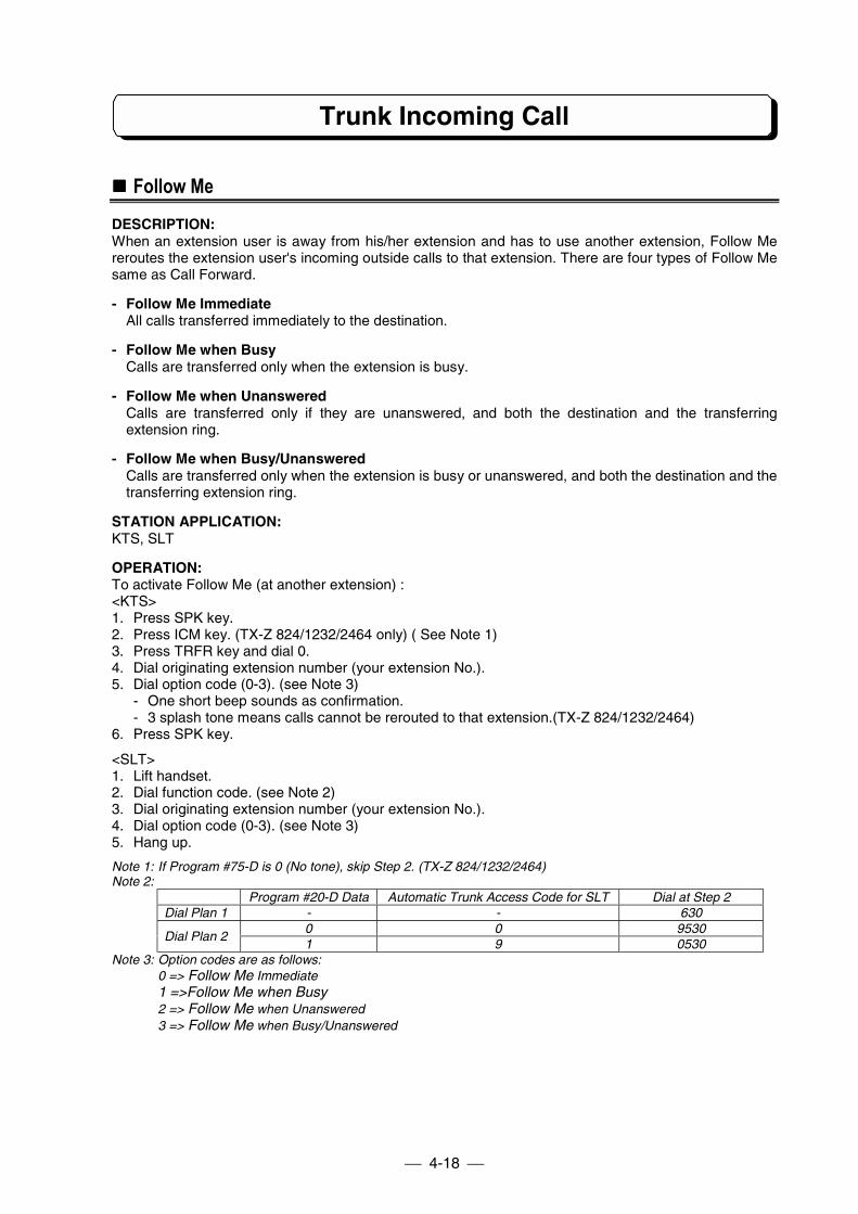
Trunk Incoming Call
4-18
!!!! Follow Me
DESCRIPTION:When an extension user is away from his/her extension and has to use another extension, Follow Mereroutes the extension user's incoming outside calls to that extension. There are four types of Follow Mesame as Call Forward.
- Follow Me ImmediateAll calls transferred immediately to the destination.
- Follow Me when BusyCalls are transferred only when the extension is busy.
- Follow Me when UnansweredCalls are transferred only if they are unanswered, and both the destination and the transferringextension ring.
- Follow Me when Busy/UnansweredCalls are transferred only when the extension is busy or unanswered, and both the destination and thetransferring extension ring.
STATION APPLICATION:KTS, SLT
OPERATION:To activate Follow Me (at another extension) :<KTS>1. Press SPK key.2. Press ICM key. (TX-Z 824/1232/2464 only) ( See Note 1)3. Press TRFR key and dial 0.4. Dial originating extension number (your extension No.).5. Dial option code (0-3). (see Note 3)
- One short beep sounds as confirmation.- 3 splash tone means calls cannot be rerouted to that extension.(TX-Z 824/1232/2464)
6. Press SPK key.
<SLT>1. Lift handset.2. Dial function code. (see Note 2)3. Dial originating extension number (your extension No.).4. Dial option code (0-3). (see Note 3)5. Hang up.
Note 1: If Program #75-D is 0 (No tone), skip Step 2. (TX-Z 824/1232/2464)Note 2:
Program #20-D Data Automatic Trunk Access Code for SLT Dial at Step 2Dial Plan 1 - - 630
0 0 9530Dial Plan 2
1 9 0530Note 3: Option codes are as follows:
0 => Follow Me Immediate1 =>Follow Me when Busy2 => Follow Me when Unanswered3 => Follow Me when Busy/Unanswered
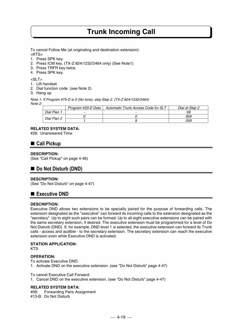
Trunk Incoming Call
4-19
To cancel Follow Me (at originating and destination extension):<KTS>1. Press SPK key.2. Press ICM key. (TX-Z 824/1232/2464 only) (See Note1)3. Press TRFR key twice.4. Press SPK key.
<SLT>1. Lift handset.2. Dial function code. (see Note 2)3. Hang up.
Note 1: If Program #75-D is 0 (No tone), skip Step 2. (TX-Z 824/1232/2464)Note 2:
Program #20-D Data Automatic Trunk Access Code for SLT Dial at Step 2Dial Plan 1 - - 69
0 0 959Dial Plan 2
1 9 059
RELATED SYSTEM DATA:#28: Unanswered Time
!!!! Call Pickup
DESCRIPTION:(See "Call Pickup" on page 4-46)
!!!! Do Not Disturb (DND)
DESCRIPTION:(See "Do Not Disturb" on page 4-47)
!!!! Executive DND
DESCRIPTION:Executive DND allows two extensions to be specially paired for the purpose of forwarding calls. Theextension designated as the "executive" can forward its incoming calls to the extension designated as the"secretary". Up to eight such pairs can be formed. Up to all eight executive extensions can be paired withthe same secretary extension, if desired. The executive extension must be programmed for a level of DoNot Disturb (DND). If, for example, DND level 1 is selected, the executive extension can forward its Trunkcalls - access and audible - to the secretary extension. The secretary extension can reach the executiveextension even while Executive DND is activated.
STATION APPLICATION:KTS
OPERATION:To activate Executive DND:1. Activate DND on the executive extension. (see "Do Not Disturb" page 4-47)
To cancel Executive Call Forward:1. Cancel DND on the executive extension. (see "Do Not Disturb" page 4-47)
RELATED SYSTEM DATA:#09: Forwarding Pairs Assignment#13-B: Do Not Disturb
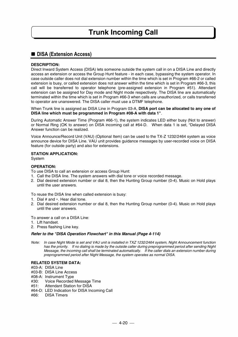
Trunk Incoming Call
4-20
!!!! DISA (Extension Access)
DESCRIPTION:Direct Inward System Access (DISA) lets someone outside the system call in on a DISA Line and directlyaccess an extension or access the Group Hunt feature - in each case, bypassing the system operator. Incase outside caller does not dial extension number within the time which is set in Program #66-2 or calledextension is busy, or called extension does not answer within the time which is set in Program #66-3, thiscall will be transferred to operator telephone (pre-assigned extension in Program #51). Attendantextension can be assigned for Day mode and Night mode respectively. The DISA line are automaticallyterminated within the time which is set in Program #66-3 when calls are unauthorized, or calls transferredto operator are unanswered. The DISA caller must use a DTMF telephone.
When Trunk line is assigned as DISA Line in Program 03-A, DISA port can be allocated to any one ofDISA line which must be programmed in Program #08-A with data 1".
During Automatic Answer Time (Program #66-1), the system indicates LED either busy (Not to answer)or Normal Ring (OK to answer) on DISA incoming call at #64-D. When data 1 is set, “Delayed DISAAnswer function can be realized.
Voice Announce/Record Unit (VAU) (Optional Item) can be used to the TX-Z 1232/2464 system as voiceannounce device for DISA Line. VAU unit provides guidance messages by user-recorded voice on DISAfeature (for outside party) and also for extensions.
STATION APPLICATION:System
OPERATION:To use DISA to call an extension or access Group Hunt:1. Call the DISA line. The system answers with dial tone or voice recorded message.2. Dial desired extension number or dial 8, then the Hunting Group number (0-4). Music on Hold plays
until the user answers.
To reuse the DISA line when called extension is busy:1. Dial # and ∗. Hear dial tone.2. Dial desired extension number or dial 8, then the Hunting Group number (0-4). Music on Hold plays
until the user answers.
To answer a call on a DISA Line:1. Lift handset.2. Press flashing Line key.
Refer to the "DISA Operation Flowchart" in this Manual (Page 4-114)
Note: In case Night Mode is set and VAU unit is installed in TXZ 1232/2464 system, Night Announcement functionhas the priority. If no dialing is made by the outside caller during preprogrammed period after sending NightMessage, the incoming call shall be terminated automatically. If the caller dials an extension number duringpreprogrammed period after Night Message, the system operates as normal DISA.
RELATED SYSTEM DATA:#03-A: DISA Line#03-B: DISA Line Access#08-A: Instrument Type#30: Voice Recorded Message Time#51: Attendant Station for DISA#64-D: LED Indication for DISA Incoming Call#66: DISA Timers
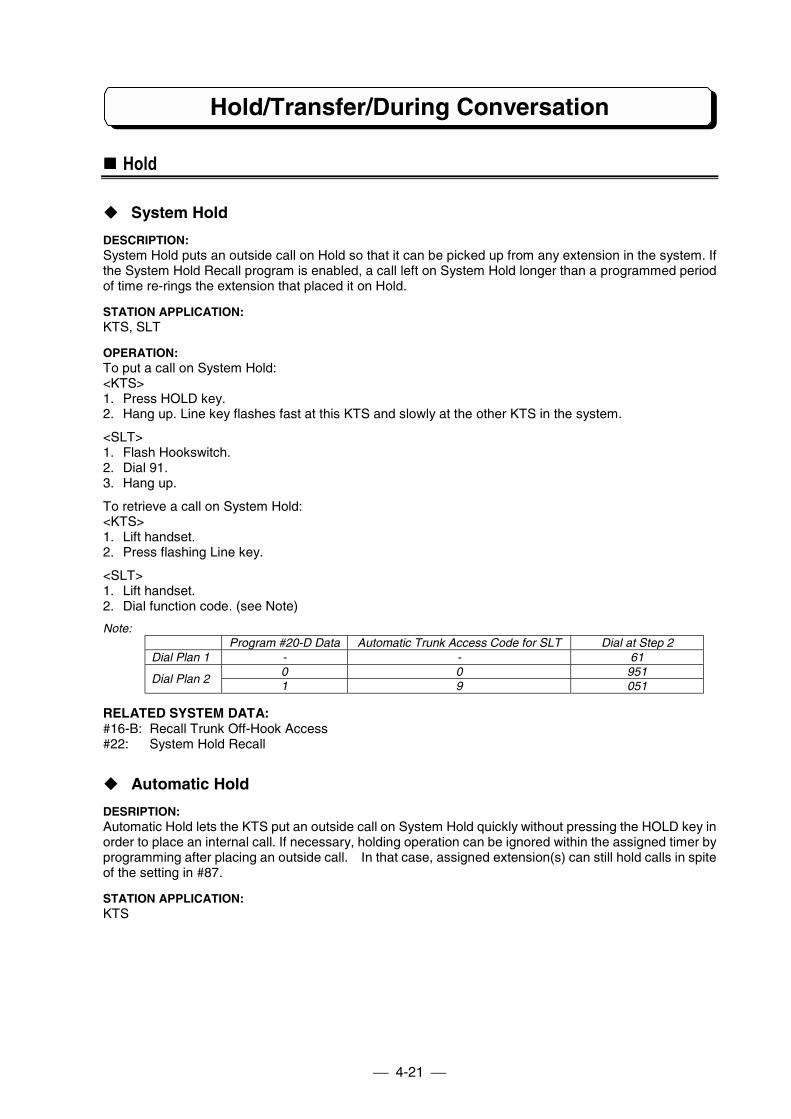
Hold/Transfer/During Conversation
4-21
!!!! Hold
" System Hold
DESCRIPTION:System Hold puts an outside call on Hold so that it can be picked up from any extension in the system. Ifthe System Hold Recall program is enabled, a call left on System Hold longer than a programmed periodof time re-rings the extension that placed it on Hold.
STATION APPLICATION:KTS, SLT
OPERATION:To put a call on System Hold:<KTS>1. Press HOLD key.2. Hang up. Line key flashes fast at this KTS and slowly at the other KTS in the system.
<SLT>1. Flash Hookswitch.2. Dial 91.3. Hang up.
To retrieve a call on System Hold:<KTS>1. Lift handset.2. Press flashing Line key.
<SLT>1. Lift handset.2. Dial function code. (see Note)
Note:Program #20-D Data Automatic Trunk Access Code for SLT Dial at Step 2
Dial Plan 1 - - 610 0 951
Dial Plan 21 9 051
RELATED SYSTEM DATA:#16-B: Recall Trunk Off-Hook Access#22: System Hold Recall
" Automatic Hold
DESRIPTION:Automatic Hold lets the KTS put an outside call on System Hold quickly without pressing the HOLD key inorder to place an internal call. If necessary, holding operation can be ignored within the assigned timer byprogramming after placing an outside call. In that case, assigned extension(s) can still hold calls in spiteof the setting in #87.
STATION APPLICATION:KTS
Hold/Transfer/During Conversation
4-22
OPERATION:To put an outside call on System Hold using Automatic Hold:1. Press the ICM key to place an extension call. The call in progress is automatically put on Hold.
RELATED SYSTEM DATA:#77: Extension Assignment 6#87: Hold Disable Timer
" Exclusive Hold
DESCRIPTION:Exclusive Hold puts an outside call on Hold at an extension so that it can only be picked up from thatextension. If not picked up within a programmed interval of time, a call on Exclusive Hold recall (re-rings)the extension that placed it on Hold. On KTS, if the recall is not answered, the call reverts to System Holdand can be picked up from any extension. On SLT, if the recall is not answered, the call reverts toextension No.10 (or attendant extension of each tenant), or cut-off.
STATION APPLICATION:KTS, SLT
OPERATION:To put an outside call on Exclusive Hold:<KTS>1. Press HOLD key twice.2. Hang up. Line key flashes fast. At all other KTS, the Line key is steadily lit (busy).
<SLT>1. Flash Hookswitch.2. Dial 92.3. Hang up.
To retrieve a call on Exclusive Hold:<KTS>1. Lift handset.2. Press flashing Line key.
<SLT>1. Lift handset.2. Dial function code. (see Note)
Note:Program #20-D Data Automatic Trunk Access Code for SLT Dial at Step 2
Dial Plan 1 - - 610 0 951
Dial Plan 21 9 051
RELATED SYSTEM DATA:#15-D: Exclusive Hold#19-E: SLT Exclusive Hold Release#21: Exclusive Hold Recall
!!!! Music On Hold
DESCRIPTION:Music On Hold sends synthesized music to an outside party on System or Exclusive Hold. The systemprovides a synthesized melody “Home sweet home”.
STATION APPLICATION:KTS, SLT
Hold/Transfer/During Conversation
4-23
OPERATION:Not applicable.
RELATED SYSTEM DATA:Not applicable.
!!!! External Music On Hold
DESCRIPTION:An external MOH music source (e.g., radio, tape player) can be used for MOH instead of internalsynthesized melody.An optional unit for External Music On Hold is required for TX-Z 308/824 system.
STATION APPLICATION:KTS, SLT
OPERATION:Not applicable.
RELATED SYSTEM DATA:#56: Relay Contact Assignment
!!!! Transfer
" Unannounced Transfer
DESCRIPTION:Unannounced Transfer lets an extension user transfer (send) a call directly to another extension - that is,without first notifying the receiving extension of the call. An Unannounced Transfer rings the receivingextension. If the receiving extension does not answer within the Unannounced Transfer Recall interval,the call recalls (re-rings) the transferring extension.
STATION APPLICATION:KTS, SLT
OPERATION:To make an Unannounced Transfer:<KTS>1. Press ICM key, then dial extension number.2. Press TRFR key or hang up. (according to #80-01-E)
<SLT>1. Flash Hookswitch.2. Dial extension number.3. Hang up.
To receive an Unannounced Transfer:<KTS>1. Lift handset. If Recall Trunk Off-Hook Access is programmed, this single step answers the call.2. Press flashing Line key (key flashes green).
<SLT>1. Lift handset.
Hold/Transfer/During Conversation
4-24
RELATED SYSTEM DATA:#16-B: Recall Trunk Off-Hook Access#23: Unannounced Transfer Recall#80-01-E: On-Hook Transfer
" Announced Transfer
DESCRIPTION:Announced Transfer automatically puts the call on System Hold so that the transferring extension cannotify the receiving extension before actually sending the call. To receive an Announced Transfer,receiving extension just wait on the line to be automatically connected to the transferred caller. Both thetransferring and receiving extensions receive a "fast flash" Hold indication, making the call easy toidentify, while all other KTSs see a "slow flash." If the call is not sent within the Announced TransferRecall interval, the call then shows a "slow flash" at the receiving extension, and re-rings the transferringextension.
STATION APPLICATION:KTS, SLT
OPERATION:To make an Announced Transfer:<KTS>1. Press ICM key, then dial extension number.2. Announce the call.3. Press TRFR key or hang up. (according to #80-01-E)
<SLT>1. Flash Hookswitch.2. Dial extension number.3. Announce the call.4. Hang up.
To receive an Announced Transfer:<KTS>1. Lift handset when notified of the call.2. Just wait on the line to be automatically connected to the transferred caller.
<SLT>1. Lift handset to answer a call.2. Just wait on the line to be automatically connected to the transferred caller.
RELATED SYSTEM DATA:#24: Announced Transfer Recall#80-01-E: On-Hook Transfer
Hold/Transfer/During Conversation
4-25
" Attendant Reverting
DESCRIPTION:When hold transfer is failed because the destination telephone did not answer and returned back tooriginating telephone, then the originating telephone did not answer, the next action is selected bysystem data (Program #19-E) as follows:1) The call will be cut off by pre-set timer (Program #29) is over.2) The call will be transferred to the Attendant Telephone.
Attendant Telephone: TX-Z 1232/2464 The pair extension of DSS console, extension No.10 oroperator station of each tenant
TX-Z 824 Extension No.10 or operator extension of each tenantTX-Z 308 Extension No.10
This timer (Program #29) will be activated as below condition.1. Put an outside call on System Hold.2. Announced Transfer Recall timer is released.3. Unannounced Transfer Recall timer is released.4. Exclusive Hold Recall timer is released.
STATION APPLICATION:KTS, SLT
OPERATION:Not applicable.
RELATED SYSTEM DATA:#08-D: Tenant Group#19-E: SLT Exclusive Hold Release/Attendant Revert Timeout#29: Attendant Reverting#52: Tenant Feature#54: Tenant Attendant#62: DSS Console Port Assignment
" Recall Trunk Display
DESCRIPTION:Executive telephone can be set to the Recall Trunk Display Mode. When Hold Recall tone is heard, thetelephone will display the held Trunk line and the telephone number.
STATION APPLICATION:KTS with LCD
OPERATION:To set/reset:1. Press SPK key.2. Press ICM key. (TX-Z 824/1232/2464 only) (See Note)3. Press OPAC key.4. Press CHECK key.
Note : If Program #75-D is 0 (No tone), skip Step 2. (TX-Z 824/1232/2464)
RELATED SYSTEM DATA:Not applicable.
Hold/Transfer/During Conversation
4-26
!!!! Park Hold (TX-Z 824/1232/2464)
DESCRIPTION:This feature permits transferring of a call placed on temporary hold on a Park Hold key. It is used totransfer an outside call to KTSs that do not appear under a key in order to answer a call on that line. ParkHold key can be assigned on Line keys. The system has four Park Hold groups. An extension can beassigned to only one Park Hold group. A line group can contain any number of lines. An extension usercan answer a call placed on Park Hold only if the extension is in the same Park Hold group. If the lineseized by Loop key is put on Park Hold, the Loop key’s LED goes off, and an idle Trunk line can beseized by pressing the Loop key.
STATION APPLICATION:KTS
OPERATION:To place a call on Park Hold:
- While on an outside call.1. Press Park Hold key.
To answer a call on Park Hold:1. Lift handset.2. Press Park Hold key.
To answer a call on I-Hold (the call placed on System Hold or Exclusive Hold by the extension user itself)in case the line which does not appear under Line key is held:1. Lift handset.2. Press ICM key. (TX-Z 824/1232/2464 only) (See Note)3. Press OPAC key.4. Dial 3.
Note : If Program #75-D is 0 (No tone), skip Step 2. (TX-Z 824/1232/2464)
RELATED SYSTEM DATA:#08-E: Park Hold Group#55: Park Hold Key Assignment
!!!! Conference
" Add-On Conference
DESCRIPTION:Add-On Conference lets an extension user establish an outside call and then add up to five other insideparties to the conversation. If Multi-Line Conference is enabled in programming, a second outside callcan be added to the conversation.
STATION APPLICATION:KTS, SLT
Hold/Transfer/During Conversation
4-27
OPERATION:
<Method 1>To establish an outside call:<KTS>1. Establish an outside call.2. Press CONF key.3. Press ICM key.4. Dial extension number of invited inside party. This party must answer using the handset.5. Press CONF. Conference established. To add more inside parties, repeat steps 2-5.
<SLT>1. Establish an outside call.2. Flash Hookswitch.3. Dial 93.4. Dial extension number of invited inside party.5. Flash Hookswitch.
Conference established. To add more inside parties, repeat steps 2-5.
<KTS/SLT>To join an Add-On Conference when invited:1. Lift handset.
<Method 2>To establish an Add-On Conference:<KTS only>1. Establish outside call.2. Press CONF key.3. Press ICM key and call the other telephones by paging and tell the Line key number. The called
parties must press the Line key to join.4. Press CONF key.
To join an Add-On Conference when invited:1. Lift handset.2. Press Line key.
RELATED SYSTEM DATA:#16-D: Add-On Conference Setup Mode
" Multi-Line Conference
DESCRIPTION:Multi-Line Conference allows an extension user to establish an outside call and then add another outsideparty to the conversation.- If desired, the user can add five more inside parties to the conversation (for a total of six inside and two
outside parties).- Another extension user can join (break into) the Conference using Break-In as long as the total number
of inside parties does not exceed six.
STATION APPLICATION:KTS, SLT
OPERATION:To establish a Multi-Line Conference:<KTS>1. Establish first outside call.2. Press CONF key. Call is put on Hold.3. Establish second outside call.4. Press CONF key. Conference is established.
Hold/Transfer/During Conversation
4-28
<SLT>1. Establish first outside call.2. Flash Hookswitch.3. Dial 94 and press 2-digit line No.4. Establish second outside call.5. Flash Hookswitch. Conference established.
To add inside parties to a Multi-Line Conference:<KTS>1. Press CONF key. Conference is put on Hold.2. Press ICM key. Hear dial tone.3. Dial extension number. Called party must lift the handset to answer.4. Press CONF key. Conference is re-established. To add more inside parties, repeat steps 1-4.
<SLT>1. Establish outside call.2. Flash Hookswitch.3. Dial 93.4. Dial extension number of invited inside party. Called party must lift the handset to answer.5. Flash Hookswitch. Conference established. To add more inside parties, repeat steps 2-5.
RELATED SYSTEM DATA:#16-E: Multi-Line Conference
" Internal Conference
DESCRIPTION:Internal Conference allows a multiple-party Intercom conversation. An extension user can establish anInternal Conference with up to five other extension users (i.e., for a total of six internal parties).
STATION APPLICATION:KTS, SLT
OPERATION:To establish an Internal Conference:<KTS>1. Establish Intercom call. The called party must answer using the handset.2. Press CONF key. Hear dial tone.3. Dial extension number of another internal party. The called party must answer using the handset.4. Once the called party answers, Conference is established. To add more internal parties, repeat steps
2-4.
Note : If Manual Mode (Program #80-01-D = 0) is assigned, Conference initiator must press CONFkey after the called party answers to establish an internal conference.
<SLT>1. Establish Intercom call. The called party must answer using the handset.2. Flash Hookswitch. Hear dial tone.3. Dial extension No. of another internal party. The called party must answer using the handset.4. Once the called party answers, Conference is established. To add more internal parties, repeat steps
2-4.
Note : If Manual Mode (Program #80-01-D = 0) is assigned, Conference initiator must flashHookswitch after the called party answers to establish an internal conference.
To join an Internal Conference when invited:<KTS, SLT>1. Lift handset and wait.
RELATED SYSTEM DATA:#80-01-D: Internal Conference Mode
Hold/Transfer/During Conversation
4-29
!!!! Long Conversation Warning (Three Minutes)
DESCRIPTION:Long Conversation Warning is a signal reminder that sounds every three minutes while an extension ison an outgoing outside call. The signal reminder is a series of three short tones that sound over thespeaker of the phone.
STATION APPLICATION:KTS
OPERATION:Not applicable.
RELATED SYSTEM DATA:#18-A: Three Minutes Warning Tone
!!!! Long Conversation Cut-Off
DESCRIPTION:A conversation on an external call (only Outgoing Call) can be forcibly terminated by the system after apre-programmed period has lapsed. Before terminating the call, a warning tone (400 Hz continuous tone)will be sent to the caller within a pre-programmed period. This feature is enabled or disabled on anextension basis.This feature permits the restriction of long conversations on certain extensions.
STATION APPLICATION:KTS, SLT
OPERATION:Not applicable.Note 1: “Conversation Timer” (Program #82-1) will be activated even if the assigned extension places an outgoing
call then transfers that Trunk line to another extension. (Conversation Timer will also be activated even iftransferred extension is set to 0 by Program #75-E.
Note 2: In the event of Multi-line Conference being established by the assigned extension, only outgoing Trunk linewill be forcibly terminated after the pre-programmed period has lapsed. The conversation betweenIncoming Trunk line and the assigned extension will still be maintained.
RELATED SYSTEM DATA:#75-E: Long Conversation Cutoff#82: Long Conversation Cutoff Timer
!!!! Break-In
DESCRIPTION:Break-In lets an extension user override the system's privacy feature - a key telephone user can breakinto an outside call at another extension, including a call on a Private Line. The intrusion may or may notbe preceded by a warning tone, depending on programming (Program #-04-A), and the warning tonecomes over the speaker of both extensions. A warning intrusion tone can be sent in every 2 seconds byprogramming (Program #78-C).
STATION APPLICATION:KTS
OPERATION:1. Lift handset or press SPK key.2. Press steadily lit Line key. This breaks into the telephone conversation on that line.
Hold/Transfer/During Conversation
4-30
RELATED SYSTEM DATA:#04-A: Break-In#78-C: Break In Warning Tone
Other Trunk Features
4-31
!!!! PBX Compatibility
DESCRIPTION:The system can accommodate Central Office (CO) lines or lines from a Private Branch Exchange (PBX)already installed at the customer site. The lines are similar in the way incoming calls are answered, butdifferent in the way outgoing calls are placed - an outgoing call on a PBX line requires an access codebefore dialing, while an outgoing call on a CO line does not. System/telephone features are available toboth types of lines, and PBX features are available to the PBX lines via the Flash feature (see Flash).
PBX Night ModeIf any of lines are from a PBX, and when the PBX is set in night mode, the lines connected to PBX areswitched to real CO lines, provision is made for such things as abbreviated dialing. If you have a PBX COAccess Code programmed with a dialed number for abbreviated dialing, such as "9 pause81448111111", when your System is in the night mode the 9 and the pause will be omitted when usingthe abbreviated dialing in night mode.
STATION APPLICATION:KTS, SLT
OPERATION:Not applicable.
RELATED SYSTEM DATA:#01-A: Line Type#26: Flash Timer#38: PBX CO Access Codes#01-D: PBX Night Mode#15-B: Night Service
!!!! Dial Mode (Tone/Pulse) Selection
DESCRIPTION:Allows the user to select the dialing mode (tone or pulse) of each CO/PBX line.- TONE(DTMF)Dial Mode
The dial signal from the extension (with tone or pulse dial mode) will be converted to TONE. TONEwill then be transmitted to the CO/PBX.
- PULSE Dial ModeThe dial signal from the extension (with tone or pulse dial mode) will be converted to PULSE. PULSEwill then be transmitted to the CO/PBX.
The assigned Dial Mode must conform to the Dial Mode of the CO lines ordered from the TELECOM orthe Dial Mode of the PBX.
STATION APPLICATION:KTS, SLT
OPERATION:Not applicable.
RELATED SYSTEM DATA:#01-B: Dial Mode#17-A: Dial Pulse Sender Speed#17-B: Make/Break Ratio#17-C: DTMF Minimum Pause Time
Other Trunk Features
4-32
!!!! Private Line
DESCRIPTION:The Private Line feature allows an incoming and/or outgoing outside line to be assigned to only oneextension for exclusive use by that extension. Any outside line can be designated as a Private Line. Allfeatures involving outside lines apply to Private Lines as well - for example, calls are placed andanswered on a Private Line as they are on any other line.1) Private Line is assigned to an extension as follows:
- A line group must be formed that contains only the Private Line. For example, if line 3 is to be usedas a Private Line, line group XX must have the following entry in Program #02: 02-XX-03-03 (i.e.,line 03 is the lowest and highest numbered line in the group).
- The line group must be assigned to only one extension in Program #06 and/or Program #07 foroutgoing and/or incoming access, respectively.
2) An extension programmed for the Break-In feature can break into a call on a Private Line.
STATION APPLICATION:KTS, SLT
OPERATION:Not applicable.
RELATED SYSTEM DATA:#02: Line Group#06: Outgoing Trunk Access#07: Incoming Trunk Access/Audible
!!!! Tenant Service
DESCRIPTION:Tenant Service allows two or more independent businesses to share the system. Each tenant can beassigned incoming and/or outgoing outside lines dedicated for its own use. Some features (Extensioncalls, Paging calls, Abbreviated Dialing, Attendant Reverting) can be partitioned among the tenants.Night Transfer can be independently used by each tenant if a "1" is entered in Program #15-B.
STATION APPLICATION:KTS, SLT
OPERATION:Not applicable.
RELATED SYSTEM DATA:#02: Line Group Assignment#06: Outgoing Trunk Access#07: Incoming Trunk Access/Audible#08-D: Tenant Group#15-B: Night Service#52: Tenant Feature#53: Tenant Abbreviated Dial#54: Tenant Attendant
Other Trunk Features
4-33
!!!! Unsupervised Conference
DESCRIPTION:Unsupervised Conference allows an extension user to establish a Conference with two outside parties,then hang up, leaving the outside parties connected. The extension user can later join the UnsupervisedConference if desired. The system can accommodate up to four Unsupervised Conference at a time, andeach Unsupervised Conference must be assigned an unused extension port in UnsupervisedConference Port Assignment (program #05), and Multi-Line Conference must be enabled inprogramming.
STATION APPLICATION:KTS
OPERATION:To establish an Unsupervised Conference:1. Establish first outside call.2. Press CONF key. The call is put on Hold.3. Establish second outside call.4. Press CONF key.
- Three-party Conference is established.5. Press CONF key.
- Both outside parties are put on Hold.6. Hang up.
- Unsupervised Conference is established.
To later join an Unsupervised Conference:1. Lift handset.2. Press either Line key of the Conference.
To terminate:1. Establish Three-party Conference.2. Hang up.
- Both outside lines become idle
Note: When both outside parties finish the call, unsupervised conference must be manually terminated bythe telephone which sets up the call.
RELATED SYSTEM DATA:#05: Unsupervised Conference Port Assignment#16-E: Multi-Line Conference
!!!! Call Timer
DESCRIPTION:Call Timer is an automatic stopwatch feature that timer outgoing outside calls on Display phones. Thedisplay changes to a stopwatch at the programmed Call Duration Start Time and the timing stops whenthe extension user hangs up. The display shows the duration of the call for approximately eight seconds,then changes to the date and time.
STATION APPLICATION:KTS with LCD
OPERATION:Not applicable.
RELATED SYSTEM DATA:#25: Call Duration Start Time
Other Trunk Features
4-34
!!!! DISA (Trunk-to-Trunk)
DESCRIPTION:Direct Inward System Access (DISA) lets someone outside the system call in on a DISA line andplace a call on a system line, bypassing the system operator. A security code is required to place anoutside call (Trunk-to-Trunk), and the Toll Restriction Class assigned to a security code determinesthe type of calls that can be placed. The DISA caller must use a DTMF telephone. The lines can bedisconnected automatically when the assigned Trunk-to-Trunk Cut-Off Timer elapses and a userdoes not dial “1” within 10 seconds.
When Trunk Line is assigned as DISA Line in Program 03-A, DISA port can be allocated to any one ofDISA line which must be programmed in Program #08-A with data 1".
Voice Announce/Record Unit (VAU) (Optional Item) can be used to the TX-Z 1232/2464 system as voiceannounce device for DISA Line. VAU unit provides guidance messages by user-recorded voice on DISAfeature (for outside party) and also for extensions.
STATION APPLICATION:System
OPERATION:
To use DISA to place a call on a system line (Trunk-to-Trunk):1. Call the DISA line. The system answers with dial tone or voice recorded message.2. Dial #.3. Dial DISA security code. Receive confirmation tone.4. Dial Queue Group number (1-6) for desired line or dial 9, then two-digit line number. If busy tone is
heard, use either procedure below to disconnect.5. Dial telephone number including PBX Access Code if required.6. Dial #. The call rings through.
To hang up the outside call and reuse the DISA line:1. Dial # and ∗. Hear dial tone.2. Dial #.3. Dial DISA security code. Receive confirmation tone.4. Dial Queue Group number (1-6) for desired line or dial 9, then two-digit line number. If busy tone is
heard, use either procedure below to disconnect.5. Dial telephone number including PBX Access Code if required.6. Dial #. The call rings through.
To disconnect both the DISA line and the system line:(When Polarity Reverse Detection is not available)1. Dial #, #.Note: This procedure must be used before hanging up. If not, the Trunk-to-Trunk condition continues until the
assigned Trunk-to-Trunk Cut-Off Timer elapses.
To disconnect both the DISA line and the system line:(When Polarity Reverse Detection is available)1. Hang up.
To continue conversation when Trunk-to-Trunk cut-off warning tone is heard:1. Dial 1.
Refer to the "DISA Operation Flowchart" in this Manual (P. 4-114)
RELATED SYSTEM DATA:#03-A: DISA Line#03-B: DISA Line Access#08-A: Instrument Type#30: Voice Recorded Message Time
Other Trunk Features
4-35
#31: Trunk-to-Trunk Cut-Off Timer Assignment#46: DISA Security Codes#47: DISA Security Code Extension Assignment#48: DISA Toll Restriction Class#64-D: LED Indication for DISA Incoming Call#66: DISA Timers
Intercom Outgoing Call
4-36
!!!! Intercom Link Increase
DESCRIPTION:There are 2 intercom links provided in the TX-Z 308, 6 intercom links in the TX-Z 824 System, and 10intercom links in the TX-Z 1232/2464 System. One link is reserved if Background Music is used in TX-Z824/1232/2464 system. If a DSS console is connected to TX-Z 1232/2464, it also occupies a link.Intercom Link Increase allows unused Trunk line circuits to be used as Intercom links, providingincreased Intercom calling capabilities. The Intercom Hold/Conference feature is disabled when Intercomlinks are increased. Nitsuko Voice Mail System (NVM Series) can not be used if intercom link isincreased.
STATION APPLICATION:System
OPERATION:Not applicable.
RELATED SYSTEM DATA:#45: Intercom Link Increase
!!!! Intercom Call
DESCRIPTION:Intercom Call allows extension-to-extension conversation. The system can be programmed for one oftwo Intercom Signaling modes: ringing or voice announce. When voice announce is programmed, anIntercom call signals the called extension with a beep (not ringing). After the beep sounds, the caller canmake a voice announcement over the speaker of the called extension.Regardless of the signaling mode programmed, an extension user can change it on a per call basis. Forexample, a ringing Intercom call can be changed to a voice announced call by dialing a code.
STATION APPLICATION:KTS, SLT
OPERATION:To place an Intercom call:<KTS>1. Lift handset or press SPK key. (See Note 1)2. Dial extension number.To convert a ringing call into a voice announced call, or vice versa, dial 1.
<SLT on Dial Plan 1>1. Lift handset.2. Dial 7, wait for dial tone.3. Dial extension number.To convert a ringing call into a voice announced call, or vice versa, dial 1.
<SLT on Dial Plan 2>1. Lift handset.2. Dial extension number.To convert a ringing call into a voice announced call, or vice versa, dial 1.
Note 1: If Program #75-D is 0 (No tone), press ICM key after Step 1 to seize Intercom. (TX-Z 824/1232/2464)Note 2: Call Monitor, Speakerphone and Single Step Access provide ways to place Intercom Calls without lifting the
handset.
RELATED SYSTEM DATA:#19-B: Intercom Call Type#75-D: Key Telephone Off-Hook Mode Selection
Intercom Outgoing Call
4-37
!!!! Direct Station Selection
DESCRIPTION:Direct Station Selection (DSS) provides an extension user with one-button access to other extensions inthe system. Each of the ten One-Touch keys on a key telephone can be programmed to call a particularextension. The One-Touch keys can also be programmed to access any Page Zone (see Paging) orDoorphone using the steps below.
STATION APPLICATION:KTS
OPERATION:To program a One-Touch key for DSS:1. Lift handset.2. Press ICM key. (TX-Z 824/1232/2464 only) (See Note)3. Press DC.4. Dial #.5. Press One-Touch key.6. Dial extension number.
orto program a Page Zone, dial 80-87. (80 - 85 for TX-Z 308)to program a Doorphone, dial 88 or 89.
7. To program more keys, repeat steps 3-6.8. Hang up.
Note : If Program #75-D is 0 (No tone), skip Step 2. (TX-Z 824/1232/2464)
To use a DSS key:1. Lift handset. If Single Step Access is programmed and the phone is equipped with a Speakerphone,
this step can be skipped.2. Press One-Touch key set as DSS key.
To hold and transfer a Trunk call using a DSS key:- Make conversation with an outside party.
1. Press a desired One-Touch key set as DSS key.- The Trunk line will automatically be held, then intercom call will be established.
2. Make announcement (if desired).3. Press TRFR key or hang up to transfer.
To display the number programmed under a DSS/One-Touch key:- Do not lift handset.
1. Press CHECK key.2. Press ICM key.3. Press One-Touch key.
- Key number displays, then stored number.4. Press CLEAR to return to normal display.
On TX-Z 308 System, One-Touch Key No.1 to No.8 are initially programmed as DSS keys for ExtensionNo.10 to No.17, One-Touch Key No.10 for All Call Paging (80).On TX-Z 824/1232/2464 System, One-Touch Key No.1 to No.9 are initially programmed as DSS forExtension No.10 to No.18, One-Touch Key No.10 for All Call Paging (80).
RELATED SYSTEM DATA:Not applicable.
Intercom Outgoing Call
4-38
!!!! Intercom Off-Hook Signaling
DESCRIPTION:Intercom Off-Hook Signaling lets an extension user send a signal to a busy extension, then wait for areplay. The signal is one short burst of tones, which comes over the speaker of the busy extension. Inaddition, the ICM key at the busy extension flashes. The busy extension user can choose not to reply tothe signal if it is inconvenient to do so.An extension can be programmed to send Intercom Off-Hook Signaling in one of two ways: manually orautomatically. The manual-type requires the user to dial a code to send the signal, while the automatic-type sends the signal automatically any time a user calls a busy extension. Intercom Off-Hook signalingcannot be sent to a busy extension when it is using Handsfree Answerback. Single Line Telephones(SLT) can send and receive the signals. Extensions programmed for Automatic Intercom Off-HookSignaling cannot use the Camp-On or Callback features.
STATION APPLICATION:KTS, SLT
OPERATION:To manually send Intercom Off-Hook Signaling:<KTS/SLT>1. Place Intercom call. Hear busy tone.2. Dial 1. Hear one short burst of tones.3. Wait for a reply. To send more tones, dial 1 again.
To use automatic Intercom Off-Hook Signaling:<KTS/SLT>1. Place Intercom call. When the called extension is busy, one short burst of tones is heard instead of
busy tone.2. Wait for a reply. To manually send more tones, dial 1.
To answer an Intercom Off-Hook Signaling:<KTS>1. Press flashing ICM. This answers the waiting call and puts an outside call in progress on Hold. This
step will, however, terminate an Intercom call in progress; Intercom calls cannot be put on Hold.<SLT>1. Flash Hookswitch (On-hook → Off-Hook). This answers the waiting call and terminates an Intercom
call in progress.
RELATED SYSTEM DATA:#04-C: Intercom Off-Hook Signaling
!!!! Group Hunt
DESCRIPTION:Group Hunt searches for an idle extension among all the extensions in a particular Hunting Group.Extensions are assigned to Hunting Groups in programming - for example, all the extensions in a salesdepartment might be assigned to Hunting Group 4. When an extension user dial a Hunting Groupnumber, the Group Hunt feature automatically calls the first idle one it finds. When all extensions in aHunting Group are busy, a user receives busy tone and can activate Callback or Camp-On. Thesefeatures automatically connect the user to the first extension programmed into that group as soon as itbecomes available. When the called extension does not answer in the preprogrammed time, the systemautomatically calls the next idle extension in the same Hunting Group according to the order in theHunting Group. The caller can also call the next idle extension by manual operation. The extension tobe searched first in the Hunting Group can be fixed or circulated (Program #80-2-A). When all extensionsin the same Hunting Group are searched and no extension answers, Group Hunt is canceled.
Intercom Outgoing Call
4-39
STATION APPLICATION:KTS, SLT
OPERATION:<KTS>1. Lift handset. (See Note 1)2. Dial # (TX-Z 824/1232/2464).
Dial 86 (TX-Z 308).3. Dial Hunting Group No. (0 - 4)
- The first idle extension is called. If the extension does not answer in the preprogrammed time, the system calls the next idle extension, or the caller can dial # to call next idle extension.
<SLT on Dial Plan 1>1. Lift handset.2. Dial 7, and wait for dial tone.3. Dial #.4. Dial Hunting Group No. (0 - 4)
- The first idle extension is called. If the extension does not answer in the preprogrammed time, the system calls the next idle extension, or the caller can dial # to call next idle extension.
Note 1 :If Program #75-D is 0 (No tone), press ICM key after Step 1 to seize Intercom (TX-Z 824/1232/2464).Note 2: SLT on Dial Plan 2 can not use this feature.Note 3: When Program #80-2-A = 1, the extension of the first order no. is called after the extension of the last order
no. is called first. If the Hunting Group calling timer expires, Group Hunt is used again, or Step Call (pressing#) is used.
RELATED SYSTEM DATA:#11: Hunting Groups#84: Hunting Group Calling Timer#80-2-A: Group Hunt Mode
!!!! Step Calling
DESCRIPTION:When an extension user makes an Intercom call and receives a busy signal or no answer, Step Callinglets the user call the other extensions, in ascending order, by just dialing a code. For example, ifextension 12 is busy, Step Calling tries extension 13. If there is no answer at extension 13, Step Callingtries extension 14, and so on. Step Calling is canceled if it reaches an extension that is not installed.
STATION APPLICATION:KTS, SLT
OPERATION:1. Place Intercom call.
- Receive busy tone or no answer.2. Dial #.
- Next extension is automatically called. To call the next extension, dial # again.
RELATED SYSTEM DATA:Not applicable.
Intercom Outgoing Call
4-40
!!!! Camp-On (Callback)
DESCRIPTION:Instead of hanging up after calling a busy extension, Camp-On lets an extension user dial a code andwait off-hook until the extension becomes available. As soon as the extension becomes free, the callautomatically goes through. Or, if the extension user hangs up after dialing the code, Callbackautomatically redials a busy extension. When the busy extension becomes free, Callback signals (rings)the extension that activated it. When the Callback signal is answered, an Intercom call is automaticallyplaced to the previously busy extension. Calls can be placed while waiting for the Callback signal, andCallback can be activated for more than one busy extension at a time. Camp-On/Callback cannot beactivated by an extension that is programmed for Automatic Intercom Off-Hook Signaling (Program #04-C). Camp-On/Callback can also be activated when a user calls a busy Hunting Group (see Group Hunt).
STATION APPLICATION:KTS, SLT
OPERATION:To activate Camp-On:1. Place Intercom call. Hear busy tone.2. Dial ∗. Busy tone stops.3. Do not hang up.4. Wait for the call to go through. Ringing is heard as soon as the extension becomes free.
To activate Callback:1. Place Intercom call. Hear busy tone.2. Dial ∗. Busy tone stops.3. Hang up.
To answer the Callback signal:- The signal sounds like an Intercom ring, but the ICM key does not flash.
1. Lift handset. Extension is called.
To cancel Callback:1. Lift handset to cancel Callback before receiving the Callback signal.2. Hang up.
RELATED SYSTEM DATA:Not applicable.
!!!! Message Waiting
DESCRIPTION:When an extension user makes an Intercom call and receives a busy signal or no answer, MessageWaiting lets this user leave a visual indication (flashing MW/Indicator light) at the busy/unattended phonerequesting a return call. An extension user can leave Message Waiting indications at several differentextensions.
STATION APPLICATION:KTS, SLT
OPERATION:To leave a Message Waiting:<KTS/SLT>1. Place Intercom call. Busy or no answer.2. Dial 0. MW/Indicator flashes intermittently as confirmation (KTS).3. Hang up.
Intercom Outgoing Call
4-41
To call the extension that left a Message Waiting indication:<KTS>1. Seize Intercom.2. Dial ∗ (TX-Z 824/1232/2464).
Dial 87 (TX-Z 308). The extension is called.3. To call the next extension that left a Message Waiting indication, dial ∗ again.
<SLT on Dial Plan 1>1. Lift handset. (Hear Message Waiting dial tone)2. Dial 7, wait dial tone. (see Note 1)3. Dial ∗.
<SLT on Dial Plan 2>1. Lift handset. (Hear Message Waiting dial tone)2. Dial ∗.
To cancel all Message Waiting indications:<KTS>1. Lift handset.2. Press ICM key. (TX-Z 824/1232/2464 only) (See Note 2)3. Dial ∗, 0, ∗ (TX-Z 824/1232/2464).
Dial 94, 0, ∗ (TX-Z 308).4. Hang up.
<SLT>1. Lift handset.2. Dial function code. (see Note 3)
To cancel an individual Message Waiting:<KTS only>1. Lift handset.2. Press ICM key. (TX-Z 824/1232/2464 only) (See Note 2)3. Dial ∗, destination extension number, ∗ (TX-Z 824/1232/2464).
Dial 94, destination extension number, ∗ (TX-Z 308).4. Hang up.
<KTS with LCD only>- Do not lift handset -
1. Press OPAC key2. Press CLEAR key. (see Note 4)
To display the extension number that left a Message Waiting:<KTS with LCD>
- Do not lift handset.1. Press CHECK key.2. Dial ∗. Extension number is displayed.3. Press Hold key to clear the Message Waiting Indication.4. Press ICM key to call back Message Waiting originating extension.5. To display the next extension number that left a Message Waiting indication, dial ∗ again.6. Press CLEAR to return to normal display.
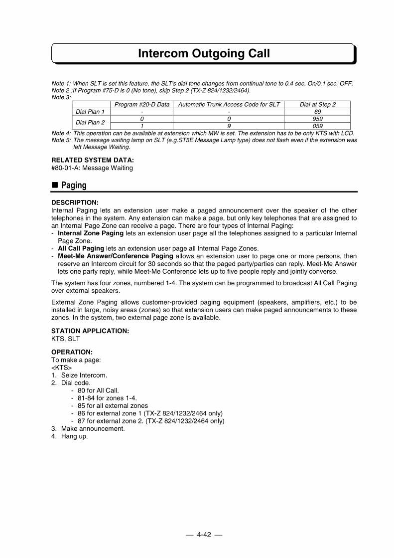
Intercom Outgoing Call
4-42
Note 1: When SLT is set this feature, the SLT's dial tone changes from continual tone to 0.4 sec. On/0.1 sec. OFF.Note 2 :If Program #75-D is 0 (No tone), skip Step 2 (TX-Z 824/1232/2464).Note 3:
Program #20-D Data Automatic Trunk Access Code for SLT Dial at Step 2Dial Plan 1 - - 69
0 0 959Dial Plan 2
1 9 059Note 4: This operation can be available at extension which MW is set. The extension has to be only KTS with LCD.Note 5: The message waiting lamp on SLT (e.g.ST5E Message Lamp type) does not flash even if the extension was
left Message Waiting.
RELATED SYSTEM DATA:#80-01-A: Message Waiting
!!!! Paging
DESCRIPTION:Internal Paging lets an extension user make a paged announcement over the speaker of the othertelephones in the system. Any extension can make a page, but only key telephones that are assigned toan Internal Page Zone can receive a page. There are four types of Internal Paging:- Internal Zone Paging lets an extension user page all the telephones assigned to a particular Internal
Page Zone.- All Call Paging lets an extension user page all Internal Page Zones.- Meet-Me Answer/Conference Paging allows an extension user to page one or more persons, then
reserve an Intercom circuit for 30 seconds so that the paged party/parties can reply. Meet-Me Answerlets one party reply, while Meet-Me Conference lets up to five people reply and jointly converse.
The system has four zones, numbered 1-4. The system can be programmed to broadcast All Call Pagingover external speakers.
External Zone Paging allows customer-provided paging equipment (speakers, amplifiers, etc.) to beinstalled in large, noisy areas (zones) so that extension users can make paged announcements to thesezones. In the system, two external page zone is available.
STATION APPLICATION:KTS, SLT
OPERATION:To make a page:<KTS>1. Seize Intercom.2. Dial code.
- 80 for All Call.- 81-84 for zones 1-4.- 85 for all external zones- 86 for external zone 1 (TX-Z 824/1232/2464 only)- 87 for external zone 2. (TX-Z 824/1232/2464 only)
3. Make announcement.4. Hang up.
Intercom Outgoing Call
4-43
<SLT>1. Lift handset2. Dial 7, wait for dial tone. (see Note)3. Dial code.
- 80 for All Call.- 81-84 for zones 1-4.- 85 for all external zones- 86 for external zone 1 (TX-Z 824/1232/2464 only)- 87 for external zone 2. (TX-Z 824/1232/2464 only)
4. Make announcement.5. Hang up.
Note: If SLT set on Dial Plan 2, skip step 2.
To initiate Meet-Me Answer:<KTS>1. Seize Intercom.2. Dial code.
- 80 for All Call.- 81-84 for zones 1-4.- 85 for all external zones- 86 for external zone 1 (TX-Z 824/1232/2464 only)- 87 for external zone 2. (TX-Z 824/1232/2464 only)
3. Page person, announce code.- 80-87: TX-Z 824/1232/2464- 930-935: TX-Z 308
4. Dial # for Meet-Me Answer5. Do not hang up. Wait for a reply.
<SLT>1. Lift handset2. Dial 7, wait for dial tone. (see Note)3. Dial code.
- 80 for All Call.- 81-84 for zones 1-4.- 85 for all external zones- 86 for external zone 1 (TX-Z 824/1232/2464 only)- 87 for external zone 2. (TX-Z 824/1232/2464 only)
4. Page person, announce code.- 80-87: TX-Z 824/1232/2464- 80-85: TX-Z 308
5. Dial # for Meet-Me Answer.6. Do not hang up. Wait for a reply.
Note: If SLT set on Dial Plan 2, skip step 2.
To reply to Meet-Me Answer:<KTS>1. Lift handset or press SPK at a phone that received the page.2. Press ICM key. (TX-Z 824/1232/2464 only) (See Note 1)3. Dial announced code.
- 80-87, or 88(same zone) : TX-Z 824/1232/2464- 930-935, or 938(same zone) : TX-Z 308
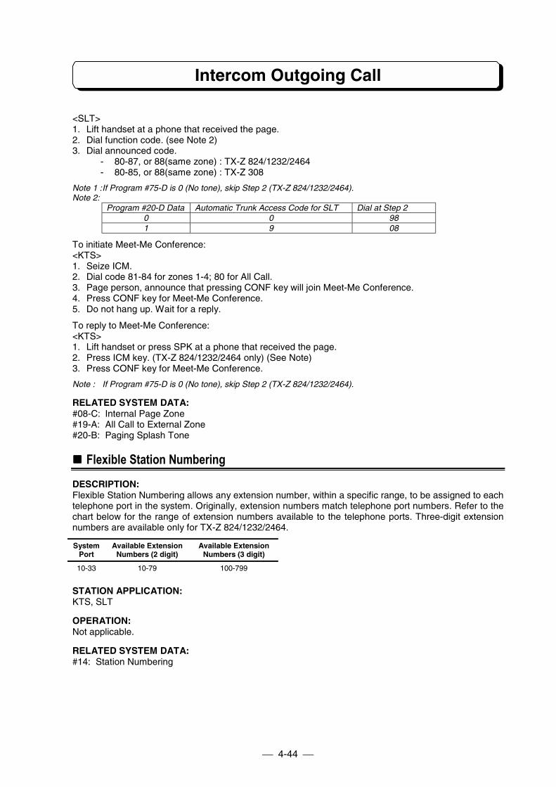
Intercom Outgoing Call
4-44
<SLT>1. Lift handset at a phone that received the page.2. Dial function code. (see Note 2)3. Dial announced code.
- 80-87, or 88(same zone) : TX-Z 824/1232/2464- 80-85, or 88(same zone) : TX-Z 308
Note 1 :If Program #75-D is 0 (No tone), skip Step 2 (TX-Z 824/1232/2464).Note 2:
Program #20-D Data Automatic Trunk Access Code for SLT Dial at Step 20 0 981 9 08
To initiate Meet-Me Conference:<KTS>1. Seize ICM.2. Dial code 81-84 for zones 1-4; 80 for All Call.3. Page person, announce that pressing CONF key will join Meet-Me Conference.4. Press CONF key for Meet-Me Conference.5. Do not hang up. Wait for a reply.
To reply to Meet-Me Conference:<KTS>1. Lift handset or press SPK at a phone that received the page.2. Press ICM key. (TX-Z 824/1232/2464 only) (See Note)3. Press CONF key for Meet-Me Conference.
Note : If Program #75-D is 0 (No tone), skip Step 2 (TX-Z 824/1232/2464).
RELATED SYSTEM DATA:#08-C: Internal Page Zone#19-A: All Call to External Zone#20-B: Paging Splash Tone
!!!! Flexible Station Numbering
DESCRIPTION:Flexible Station Numbering allows any extension number, within a specific range, to be assigned to eachtelephone port in the system. Originally, extension numbers match telephone port numbers. Refer to thechart below for the range of extension numbers available to the telephone ports. Three-digit extensionnumbers are available only for TX-Z 824/1232/2464.
SystemPort
Available ExtensionNumbers (2 digit)
Available ExtensionNumbers (3 digit)
10-33 10-79 100-799
STATION APPLICATION:KTS, SLT
OPERATION:Not applicable.
RELATED SYSTEM DATA:#14: Station Numbering
Intercom Outgoing Call
4-45
!!!! Dual Handsfree Hotline
DESCRIPTION:Dual Handsfree Hotline allows one extension to simultaneously call two other extensions. The"secretary" extension can make a voice announced Intercom call over the speaker of both "executive"extensions. The users at the executive extensions can reply Handsfree (i.e., by just speaking toward thephone) and all three parties can converse. The simultaneous call goes through only if both executiveextensions are idle and an executive extension has not forwarded Intercom calls. In order to replyHandsfree, the microphone at an executive extension must be on. When an executive replies by liftingthe handset, the other executive is disconnected. The secretary can make a ringing Intercom call to bothexecutives; however, an executive must lift the handset to reply, which disconnects the other executive.
STATION APPLICATION:KTS
OPERATION:1. Seize Intercom at secretary extension.2. Dial either executive extension number. Both are called. If ringing is heard, the secretary can dial 1 to
convert the call into a voice announced call. If busy tone is heard, the secretary can still contact theother executive by dialing the other executive extension number after pressing ICM.
RELATED SYSTEM DATA:#10: Dual Handsfree Hotline
Intercom Incoming Call
4-46
!!!! Intercom Answer
DESCRIPTION:Intercom Answer (just lifting the handset) lets an extension user answer either signal intercom call orvoice announced intercom call in a single step.Handsfree Answerback lets a key telephone extension user answer a voice announced Intercom callwithout touching the phone.
STATION APPLICATION:KTS, SLT
OPERATION:
To answer an Intercom call:<KTS/SLT>1. Lift handset.
To answer a voice announced call using Handsfree Answerback:<KTS only>1. Speak toward the phone. The microphone must be on.
RELATED SYSTEM DATA:Not Applicable
!!!! Call Pickup
DESCRIPTION:Call Pickup provides two distinct functions: one function applies to Intercom calls and the other to outsidecalls.- Call Pickup allows the extension users to answer Intercom calls and Doorphone call. An Intercom call
that is ringing (or voice-announced) at a particular extension can be answered from any otherextension in the system.
- Call Pickup also allows the extension users to answer a Trunk incoming call, incoming call on a DISAline, and Unannounced Transfer.
In order to pick up someone else's Intercom call, an extension user must know the number of theextension that is ringing. If the ringing and answering extensions are in the same Internal Page Zone(Program #08-C), the # key can be used to pick up the Internal call.
STATION APPLICATION:KTS, SLT
OPERATION:To use Call Pickup to answer an Intercom call, incoming call on a DISA line Unannounced Transfer, andTrunk incoming call on a extension in own pick-up group:<KTS>1. Lift handset or press SPK key.2. Press ICM key. (TX-Z 824/1232/2464 only) (See Note1)3. Dial #. If more than one extension is ringing, this code answer intercom call, unannounced transfer,
incoming call on a DISA line, and Trunk incoming call.
<SLT on Dial Plan1/2>1. Lift handset.2. Dial #.
<SLT on Dial Plan 1 only>1. Lift handset.2. Dial 8.
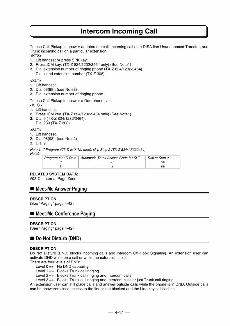
Intercom Incoming Call
4-47
To use Call Pickup to answer an Intercom call, incoming call on a DISA line Unannounced Transfer, andTrunk incoming call on a particular extension:<KTS>1. Lift handset or press SPK key.2. Press ICM key. (TX-Z 824/1232/2464 only) (See Note1)3. Dial extension number of ringing phone (TX-Z 824/1232/2464).
Dial ∗ and extension number (TX-Z 308).
<SLT>1. Lift handset.2. Dial 08(98). (see Note2)3. Dial extension number of ringing phone.
To use Call Pickup to answer a Doorphone call:<KTS>1. Lift handset.2. Press ICM key. (TX-Z 824/1232/2464 only) (See Note1)3. Dial 9 (TX-Z 824/1232/2464).
Dial 939 (TX-Z 308).
<SLT>1. Lift handset.2. Dial 08(98). (see Note2)3. Dial 9.
Note 1: If Program #75-D is 0 (No tone), skip Step 2 (TX-Z 824/1232/2464).Note2:
Program #20-D Data Automatic Trunk Access Code for SLT Dial at Step 20 0 981 9 08
RELATED SYSTEM DATA:#08-C: Internal Page Zone
!!!! Meet-Me Answer Paging
DESCRIPTION:(See "Paging" page 4-42)
!!!! Meet-Me Conference Paging
DESCRIPTION:(See "Paging" page 4-42)
!!!! Do Not Disturb (DND)
DESCRIPTION:Do Not Disturb (DND) blocks incoming calls and Intercom Off-Hook Signaling. An extension user canactivate DND while on a call or while the extension is idle.There are four levels of DND:
Level 0 => No DND capabilityLevel 1 => Blocks Trunk call ringingLevel 2 => Blocks Trunk call ringing and Intercom callsLevel 3 => Blocks Trunk call ringing and Intercom calls or just Trunk call ringing
An extension user can still place calls and answer outside calls while the phone is in DND. Outside callscan be answered since access to the line is not blocked and the Line key still flashes.
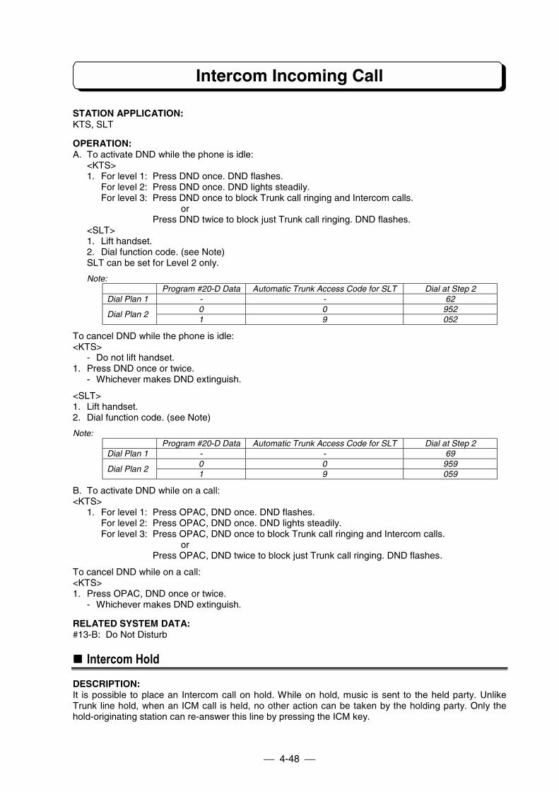
Intercom Incoming Call
4-48
STATION APPLICATION:KTS, SLT
OPERATION:A. To activate DND while the phone is idle:
<KTS>1. For level 1: Press DND once. DND flashes.
For level 2: Press DND once. DND lights steadily.For level 3: Press DND once to block Trunk call ringing and Intercom calls.
orPress DND twice to block just Trunk call ringing. DND flashes.
<SLT>1. Lift handset.2. Dial function code. (see Note)SLT can be set for Level 2 only.
Note:Program #20-D Data Automatic Trunk Access Code for SLT Dial at Step 2
Dial Plan 1 - - 620 0 952
Dial Plan 21 9 052
To cancel DND while the phone is idle:<KTS>
- Do not lift handset.1. Press DND once or twice.
- Whichever makes DND extinguish.
<SLT>1. Lift handset.2. Dial function code. (see Note)
Note:Program #20-D Data Automatic Trunk Access Code for SLT Dial at Step 2
Dial Plan 1 - - 690 0 959
Dial Plan 21 9 059
B. To activate DND while on a call:<KTS>
1. For level 1: Press OPAC, DND once. DND flashes.For level 2: Press OPAC, DND once. DND lights steadily.For level 3: Press OPAC, DND once to block Trunk call ringing and Intercom calls.
orPress OPAC, DND twice to block just Trunk call ringing. DND flashes.
To cancel DND while on a call:<KTS>1. Press OPAC, DND once or twice.
- Whichever makes DND extinguish.
RELATED SYSTEM DATA:#13-B: Do Not Disturb
!!!! Intercom Hold
DESCRIPTION:It is possible to place an Intercom call on hold. While on hold, music is sent to the held party. UnlikeTrunk line hold, when an ICM call is held, no other action can be taken by the holding party. Only thehold-originating station can re-answer this line by pressing the ICM key.
Intercom Incoming Call
4-49
STATION APPLICATION:KTS
OPERATION:To put an Intercom call on Hold:1. Press Hold. (see note)
Note: Do not hang up while an intercom call is on Hold. If you hang up the handset, your intercom call is terminated.
To retrieve an Intercom call on Hold:1. Press ICM key.
RELATED SYSTEM DATA:Not applicable.
!!!! Intercom Call Transfer
DESCRIPTION:Intercom calls may be transferred to any extension manually.There are two methods of transferring Intercom calls.
STATION APPLICATION:KTS, SLT
OPERATION:<KTS>A. To make an Intercom Call Transfer using Intercom Hold:
1. Intercom call between A and B.2. Press HOLD key to put B on Hold.3. Extension C dials extension number of A (TX-Z 824/1232/2464).
Extension C dials ∗ and extension number of A (TX-Z 308).- If extension C is SLT, dial access code 08 or 98 then dial extension number of A. (See Note)
4. Intercom call between B and C is established.
Note:Program #20-D Data Automatic Trunk Access Code for SLT Dial at Step 3
0 0 981 9 08
<KTS, SLT>B. To make an Intercom Call Transfer using Internal Conference (See Conference on Page 4-26 )
1. Intercom call between A and B.2. Establish an Internal Conference with C.3. Extension A hang up.
RELATED SYSTEM DATA:Not applicable.
!!!! Call Forward
DESCRIPTION:(See "Call Forward" page 4-16)
!!!! Follow Me
DESCRIPTION:(See "Follow Me" page 4-18)
Intercom Incoming Call
4-50
!!!! Executive DND
DESCRIPTION:(See "Executive DND" page 4-19)
Other Intercom Features
4-51
!!!! BGM (TX-Z 824/1232/2464)
DESCRIPTION:Background Music (BGM), from a customer-provided music source such as radio, can be broadcast overthe speakers of the KTS. BGM plays while an extension is not in use. When Program #49 is enabled,BGM can also be broadcast over speakers in the external page zones. If BGM is enabled, one intercomlink is used exclusively for BGM.
STATION APPLICATION:KTS
OPERATION:To turn BGM on or off while an extension is not in use:
- Do not lift handset.1. Press #.
RELATED SYSTEM DATA:#49: External Zone BGM/Alarm#56: Relay Contact Assignment
!!!! External Paging
DESCRIPTION:External Page Output allows incoming Trunk audible, BGM from an external source, and/or alarm signalsto be broadcast over speakers that are installed in the external page zone(s).
STATION APPLICATION:External Speaker
OPERATION:Not applicable.
RELATED SYSTEM DATA:#02: Line Group Assignment#49: External Zone BGM/Alarm#50: External Zone Trunk Audible
!!!! Doorphone
DESCRIPTION:A Doorphone, usually placed next to an entrance door, is a combination of doorbell and Intercom. Whensomeone presses the CALL button on the Doorphone, chime tones are sent to the designatedextensions. When an extension user answers the chimes, a two-way conversation is possible with theperson at the door. An extension user can also call a Doorphone. The system can accommodate up totwo Doorphones; both boxes can be used at the same time. Doorphone 1 sends different types of chimetones than Doorphone 2. When the chime is ringing or answered, an Intercom link is used.The extension(s) assigned in #61-E shall be out of service for Doorphone facilities (not call/notanswer/not pickup Doorphone).
STATION APPLICATION:KTS, SLT
Other Intercom Features
4-52
OPERATION:To answer the chime tones from a phone that receives them:<KTS/SLT>1. Lift handset. Connection established.
To answer the chime tones from a phone that does not receive them (Call Pickup):<KTS>1. Lift handset.2. Press ICM key. (TX-Z 824/1232/2464 only) (See Note1)3. Dial 9 (TX-Z 824/1232/2464).
Dial 939 (TX-Z 308).4. Connection established.
<SLT>1. Lift handset.2. Dial access code 08 or 98. (see Note2)3. Dial 9.
Note 1: If Program #75-D is 0 (No tone), skip Step 2 (TX-Z 824/1232/2464).Note 2:
Program #20-D Data Automatic Trunk Access Code for SLT Dial at Step 20 0 981 9 08
To call a Doorphone:<KTS>1. Seize Intercom.2. Dial 88 for box 1, 89 for box 2.
<SLT>1. Lift handset.2. Dial 7.3. Dial 88 for box 1, 89 for box 2.
Note: If SLT set on Dial Plan 2, skip step 2.
RELATED SYSTEM DATA:#12: Doorphone Call#20-A: Door Chime Tone Duration#20-C: Door Alert Tone#20-E: Existance of Doorphone Box#61-E: Doorphone Call/Answer
!!!! Door Lock Control
DESCRIPTION:A customer-provided Door Lock Control device can be installed with one of the Doorphones so that theextension users can lock/unlock that door using their phones. The door can be locked/unlocked while anextension user is talking to the door box. Relay Contact Assignment must be programmed for the device.Door relay can be changed to lock/unlock manually, or once the door is unlocked, automatic-lock isprovided according to the assigned timer.
STATION APPLICATION:KTS, SLT
Other Intercom Features
4-53
OPERATION:To unlock/lock the door after contacting the Doorphone:<KTS>1. Press FLASH key to unlock the door.2. Press FLASH key again to lock the door.
<SLT>1. Flash Hookswitch to unlock the door.2. Flash Hookswitch again to lock the door.
The door can be locked automatically when doorphone call is terminated. When using the automaticlock feature, skip step 2.
Note: If you use Recall key on the SLT, you must enter the system data(#95-1) for the Flash time of SLT.
RELATED SYSTEM DATA:#56: Relay Contact Assignment#88: Door Relay Timer#95-1: SLT Hook Detection Time
!!!! Room Monitor
DESCRIPTION:Room Monitor lets one extension monitor (listen to) the environmental sounds in an area or roomcontaining another extension. Several extensions can monitor the same extension; however, only onemonitored extension can be assigned in a system.
STATION APPLICATION:KTS
OPERATION:To activate or cancel Room Monitor at the extension to be monitored:1. Lift handset.2. Press ICM key. (TX-Z 824/1232/2464 only) (Note)3. Press OPAC.4. Press FLASH.
- MON flashes fast on TD/TXD type telephone while Room Monitor is activated.- MIC flashes fast on BTD/BTXD type telephone while Room Monitor is activated.
5. Hang up.
Note: If Program #75-D is 0 (No tone), skip Step 2 (TX-Z 824/1232/2464).
To activate or cancel Room Monitor at the monitoring extension:- Do not lift handset.
1. Press OPAC.2. Press FLASH.
- MON flashes intermittently on TD/TXD type telephone while Room Monitor is activated.- MIC flashes intermittently on BTD/BTXD type telephone while Room Monitor is activated.
This feature can be stored under the One-touch key.
RELATED SYSTEM DATA:#19-D: Room Monitor
Other Intercom Features
4-54
!!!! DSS Console (TX-Z 1232/2464)
DESCRIPTION:DSS Console gives an extension user a Busy Lamp Field (Idle/Busy/DND/MW) and one-button access toextension, Doorphone or Paging. This saves time for users that do a lot of processing (e.g., Operator).TX-Z 1232 System can connect one DSS Console. TX-Z 2464 System can connect Maximum 2 DSSConsoles. Pair extension of each DSS Console is assigned in Program. When a DSS Console isconnected, an intercom link is used exclusively for DSS Console. The Pair extension must be KTS. (It isrecommended to be KTS with LCD.) Each DSS Console must be connected to the LAST PORT of eachunit.DSS Console features and operations are as follows;
1. DSS Call (One-Touch Extension Access)DESCRIPTIONUser can make intercom conversation by only pressing the DSS key. Each DSS key is assignedfollowing extension number (which is set the in Program 14) accordingly. (Not by physical port) Pairextension operated DSS Call can not use CONF, TRFR, HOLD keys within intercom conversation.
OPERATION1. Lift handset or press SPK.2. Press one of DSS key.
RELATED FEATURESIntercom CallsFlexible Station Numbering
2. Automatic Hold of Trunk LineDESCRIPTIONWhen DSS Console user make conversation with Outside Caller, user can transfer this line for theother extension. When user is transferring the Trunk Line, the Trunk Line is held automatically.
OPERATION1. On the Trunk Line call.2. Press one of DSS key.
RELATED FEATURESHold - Automatic Hold
3. PagingDESCRIPTIONExternal and Internal Paging is possible by the single button operation. The following keys are usedfor Paging from a DSS position. When this feature is activated, Meet-me Answer and Meet-meConference are disabled.
AC: All CallIZ1: Internal Paging (For Zone 1)IZ2: Internal Paging (For Zone 2)IZ3: Internal Paging (For Zone 3)IZ4: Internal Paging (For Zone 4)EAZ: External All PagingEZ1: External Paging (For Zone 1)EZ2: External Paging (For Zone 2)
Other Intercom Features
4-55
OPERATION1. Lift handset or press SPK.2. Press one of Paging key.
(Refer to previous table)
RELATED FEATURESPaging
4. Doorphone CallDESCRIPTIONUser can make Doorphone Call only pressing the DOOR key. DSS Console has 2 DOOR keys(DOOR1 and DOOR 2). These keys are assigned to each Doorphone. DSS Console can also haveDoor Lock Control feature.
OPERATION1. Lift handset or press SPK.2. Press one of DOOR key.
RELATED FEATURESDoorphoneDoor Lock Control
5. Message WaitingDESCRIPTIONDSS Console has a MW Lamp same as the other extension. When the MW Lamp is flashing, it meansa Message is waiting for you to call back.
OPERATIONTo set the Message Waiting:1. Dial extension No. or press one of DSS key.
(This extension is Busy or No-answer.)2. Press MW key on the DSS Console.
(The MW Lamp and the message waiting extension LED on the console flash slowly.)(The MW Lamp/Indicator on the message waiting extension flashes quickly.)
To clear the message waiting:1. On-Hook condition.2. Press MW key and DSS key which is set the MW.
RELATED FEATURESMessage Waiting
6. Unannounced TransferDESCRIPTIONWhen transferring a Trunk Line call, pressing the TRFR key sends a calling tone to the transferredextension until the held line is picked up by the transferred party.
Other Intercom Features
4-56
OPERATIONTo transfer the call:1. On the Trunk Line call.2. Press one of DSS key.
(Trunk Line is held and calls the other extension.)3. Press TRFR key on DSS Console (or hang up).
(Called extension is ringing.)
At the called extension:1. Lift handset.
RELATED FEATURESUnannounced Transfer
7. Announced TransferDESCRIPTIONWhen transferring a Trunk Line call, user can transfer automatically after Intercom call.
OPERATIONTo transfer the call:1. On the Trunk Line call.2. Press one of DSS key.
(Trunk Line is held and calls the other extension.)3. Make announcement.4. Press TRFR key on DSS Console (or hang up ).
(Trunk Line call is transferred.)
RELATED FEATURESAnnounced Transfer
8. Night ServiceDESCRIPTIONThis feature is available only at #10 station. But if DSS Console is connected to the System, thisfeature is available only at DSS Console. Refer to the "Night Service” on page 4-15.
OPERATIONTo activate Night Service:1. Press NT key. (LED lights)
To cancel Night Service:1. Press NT key. (LED extinguishes)
RELATED FEATURESNight Service
9. Changing Voice/Signal CallDESCRIPTIONDSS Console can change the Intercom calling mode simply by depressing the SG/VC keyalternatively. For example, when call mode is Signal Call mode, user can change to Voice Call modeby pressing this key.
OPERATION1. Call to the other extension.2. Press SG/VC key.
RELATED FEATURESIntercom Call
Other Intercom Features
4-57
10. Intercom Off-Hook SignalingDESCRIPTIONDSS Console can activate the Off-Hook Signaling mode by pressing the SG/VC key after getting abusy tone.OPERATION1. Call to the other extension.
(This extension is Busy or No-answer.)2. Press SG/VC key.
RELATED FEATURESIntercom Off-Hook Signaling
11. DND OverrideDESCRIPTIONDSS Console can call to intercom even if the extension is set DND.
OPERATION1. Press one of DSS key.
RELATED FEATURESDo Not Disturb
12. Mode SwitchingDESCRIPTIONIn Hotel/Motel environment, DSS can indicate extension status in three mode (Business, RoomStatus, and Wakeup). See “Hotel/Motel Features - DSS Mode Switching” in Page 4-77.
13.Dial Block/Wakeup Call Status ConfirmationDESCRIPTIONIn Hotel/Motel environment, DSS console can indicate the setting status of Dial Block and WakeupCall on the display of paired extension. See “Hotel/Motel Features - Dial Block/Wakeup Call StatusConfirmation” in Page 4-83.
RELATED SYSTEM DATA:#52: Tenant Feature#62: DSS Console Port Assignment#63-A: Automatic Hold of Line#63-B: DND Override
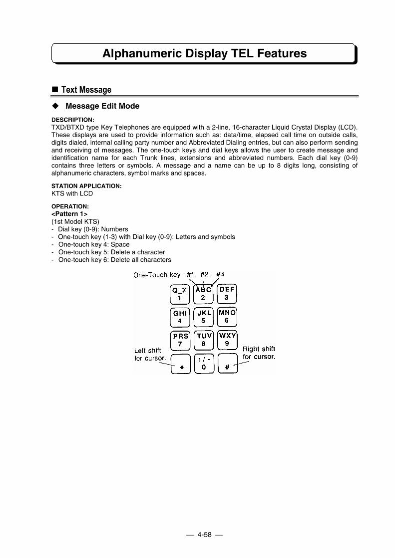
Alphanumeric Display TEL Features
4-58
!!!! Text Message" Message Edit Mode
DESCRIPTION:TXD/BTXD type Key Telephones are equipped with a 2-line, 16-character Liquid Crystal Display (LCD).These displays are used to provide information such as: data/time, elapsed call time on outside calls,digits dialed, internal calling party number and Abbreviated Dialing entries, but can also perform sendingand receiving of messages. The one-touch keys and dial keys allows the user to create message andidentification name for each Trunk lines, extensions and abbreviated numbers. Each dial key (0-9)contains three letters or symbols. A message and a name can be up to 8 digits long, consisting ofalphanumeric characters, symbol marks and spaces.
STATION APPLICATION:KTS with LCD
OPERATION:<Pattern 1>(1st Model KTS)- Dial key (0-9): Numbers- One-touch key (1-3) with Dial key (0-9): Letters and symbols- One-touch key 4: Space- One-touch key 5: Delete a character- One-touch key 6: Delete all characters
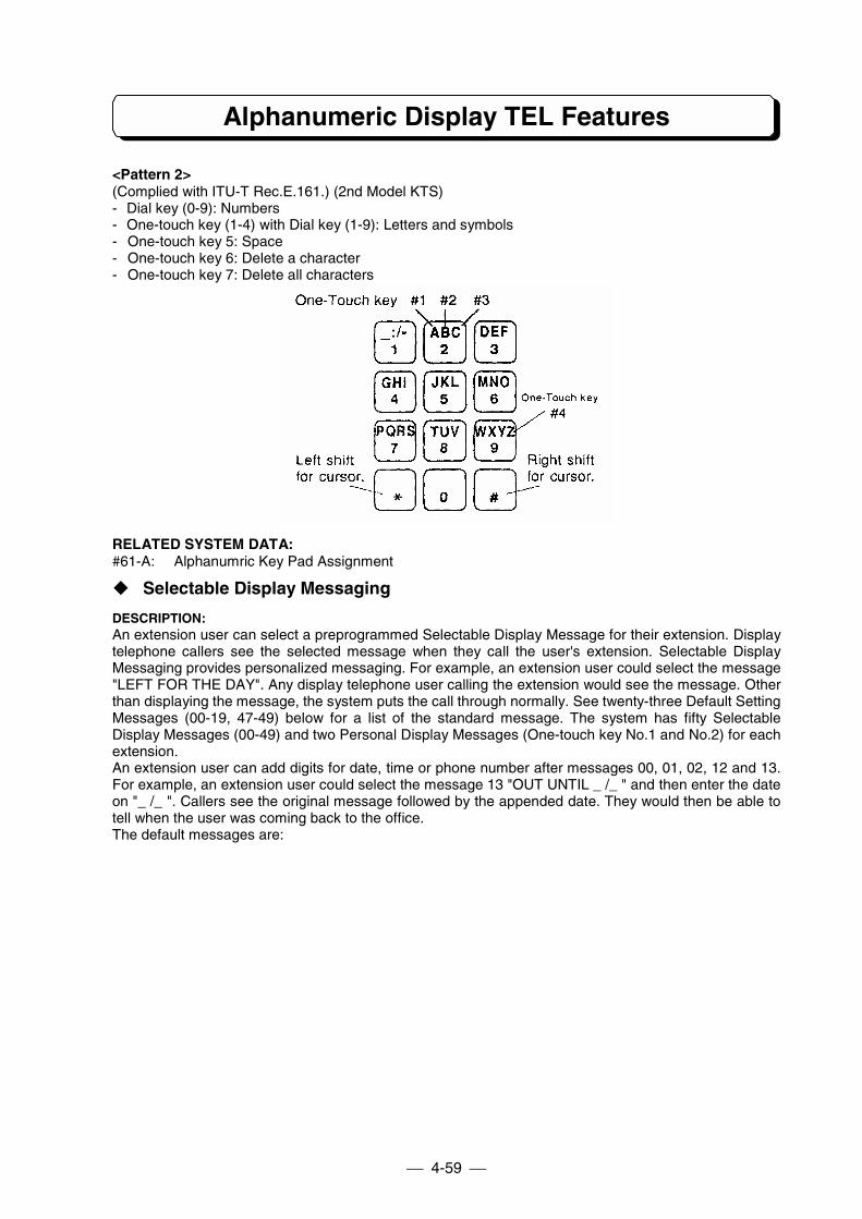
Alphanumeric Display TEL Features
4-59
<Pattern 2>(Complied with ITU-T Rec.E.161.) (2nd Model KTS)- Dial key (0-9): Numbers- One-touch key (1-4) with Dial key (1-9): Letters and symbols- One-touch key 5: Space- One-touch key 6: Delete a character- One-touch key 7: Delete all characters
RELATED SYSTEM DATA:#61-A: Alphanumric Key Pad Assignment
" Selectable Display Messaging
DESCRIPTION:An extension user can select a preprogrammed Selectable Display Message for their extension. Displaytelephone callers see the selected message when they call the user's extension. Selectable DisplayMessaging provides personalized messaging. For example, an extension user could select the message"LEFT FOR THE DAY". Any display telephone user calling the extension would see the message. Otherthan displaying the message, the system puts the call through normally. See twenty-three Default SettingMessages (00-19, 47-49) below for a list of the standard message. The system has fifty SelectableDisplay Messages (00-49) and two Personal Display Messages (One-touch key No.1 and No.2) for eachextension.An extension user can add digits for date, time or phone number after messages 00, 01, 02, 12 and 13.For example, an extension user could select the message 13 "OUT UNTIL _ /_ " and then enter the dateon "_ /_ ". Callers see the original message followed by the appended date. They would then be able totell when the user was coming back to the office.The default messages are:
Alphanumeric Display TEL Features
4-60
00: CALL _ _ _ _ _ _ _01: CALL AFTER _ _:_ _02: CALL EXT. _ _03: CALL ME ASAP04: DO NOT DISTURB05: IN CONFERENCE06: IN MEETING07: LEFT FOR THE DAY08: ON BREAK09: ON VACATION10: OUT OF OFFICE11: OUT TO LUNCH12: OUT UNTIL _ _ : _ _13: OUT UNTIL _ _ / _ _14: PAGE ME15: PLEASE SEE ME16: SEE ME ASAP17: WITH A CLIENT18: WITH A PATIENT19: WITH A VISITOR47: TAKE MESSAGE48: PLEASE HOLD49: CALL BACK LATER.
STATION APPLICATION:KTS with LCD
OPERATION:To store text in One-touch key No.1 and No.2:1. Press CHECK and OPAC.2. Dial message number (00-49).3. Dial ∗.4. Edit your own message by Message Edit Mode.5. Press CHECK.6. Press One-touch key No.1 or No.2 to store.7. Dial ∗.8. Enter message number for next storing.
orPress CLEAR to finish.
To store system message (No.10 telephone only):1. Press CHECK and OPAC.2. Dial message number (00-49).3. Dial ∗.4. Edit message by Message Edit Mode.5. Press CHECK.6. Dial message number to store.7. Dial ∗.8. Dial message number for next storing.
orPress CLEAR to finish.
RELATED SYSTEM DATA:Not applicable.
Alphanumeric Display TEL Features
4-61
" Broadcasting the Message at Later Time
DESCRIPTION:Text message can be set to indicate on display telephones in hunt group at programmed time. If it is set,and time comes, the message will appear on display in 1 minute with alarm tone.
STATION APPLICATION:KTS with LCD
OPERATION:To set send-later message:1. Press CHECK and OPAC.2. Dial message number (00-49), dial ∗.
orPress One-touch key No.1 or No.2 for personal message, then dial ∗.
3. Edit message if required.4. Press ICM.5. Dial an extension number or hunt group number (00-04).6. Press ICM key to set more extension if required. (This step is only available when extension number
is dialed at step 5.)7. Dial ∗.8. Enter the time of indication with 4 digits
(e.g. PM3:00 => 1500)9. Dial ∗.
To cancel send-later message:1. Press CHECK key.2. Press TRFR key.
To stop the alarm tone and clear the display:1. Press CLEAR key.
RELATED SYSTEM DATA:Not applicable.
" DND Message
DESCRIPTION:DND Message send a message to a calling extension when your telephone have activated DND forIntercom calls.
STATION APPLICATION:KTS with LCD
OPERATION:To set DND message using preset messages:1. Press TRFR.2. Dial message number (00-49), dial ∗.
orPress One-touch key No.1 or No.2 for personal message, then dial ∗.- DND flashes intermittently as confirmation.
To set DND message that edited by Message Edit Mode.1. Press TRFR and FLASH.2. Edit message by Message Edit Mode.3. Press FLASH and ∗. DND flashes intermittently as confirmation.
To cancel message on the telephone:1. Press CLEAR.
Alphanumeric Display TEL Features
4-62
To activate/cancel previous message (last time you set message for DND):1. Press TRFR and ∗.
- When DND message is activated, DND flashes intermittently.
RELATED SYSTEM DATA:Not applicable.
" Leave Message with MW
DESCRIPTION:When an extension user makes an Intercom call to display phone and receives a busy signal or noanswer, this user leave a text message with Message Waiting (MW).
STATION APPLICATION:KTS with LCD
OPERATION:To leave a Message:1. Place Intercom call. Busy or no answer.2. Dial 0. MW/Indicator flashes intermittently as confirmation.
- Display shows "LEAVE MESSAGE ?", then you can enter a message. If you replace handset afterthis step operation, it is simple message waiting procedure.
3. Dial ∗.4. Dial message number (00-49), dial ∗.
orPress One-touch key No.1 or No.2 for personal message, then dial ∗.
orPress FLASH, edit a message by Message Edit Mode, then press FLASH again and dial ∗.- A text message is left on called display phone.
To cancel message at message-originated telephone:1. Press CHECK and #.
- First message appears on the display.2. Use ∗ to advance and use # to backward.3. Press HOLD to cancel message.
orPress CLEAR to return to idle condition.
To call back or delete message at message-received telephone:1. Press CHECK and ∗.
- First message appears on the display.2. Use ∗ to advance and use # to backward.3. Press ICM to call back.
orPress HOLD to delete message.
orPress CLEAR to return to idle condition.
RELATED SYSTEM DATA:Not applicable.
" Camp-On Message
DESCRIPTION:When an extension user makes an Intercom call to display phone and receives a busy signal, call can notbe connected. This user can send a text message. Intercom Off-hook Signaling (#04-C) must be enabledat the called extension.
STATION APPLICATION:KTS with LCD
Alphanumeric Display TEL Features
4-63
OPERATION:To set Camp-On message:1. Place Intercom call. Hear busy tone.2. Activate Intercom Off-hook Signaling (see Intercom Off-hook Signaling on page 4-38).3. Press ∗.4. Dial message number (00-49) and ∗.
orPress One-touch key No.1 or No.2 for personal message, then dial ∗.
orPress FLASH, edit a message by Message Edit Mode, then press FLASH again and dial ∗.- Confirmation tone is heard when message is sent.
RELATED SYSTEM DATA:#04-C: Intercom Off-hook Signaling
" Reverse Message
DESCRIPTION:The extension received "Intercom Off-Hook Signaling" can send a text message to calling extension ifthis extension user is inconvenient to reply to the signal. For example, an extension user could select themessage 49 "CALL BACK LATER ".
STATION APPLICATION:KTS with LCD
OPERATION:- On conversation, "Intercom Off-Hook Signal" received.
1. Press TRFR.2. Dial message number (1-3).
Dial 1: System common message No.47Dial 2: System common message No.48Dial 3: System common message No.49
The default value of 47, 48 and 49 are:No.47: TAKE MESSAGENo.48: PLEASE HOLDNo.49: CALL BACK LATER
RELATED SYSTEM DATA:#04-C: Intercom Off-hook Signaling
!!!! Time and Date
DESCRIPTION:A Display phone connected to port 10 can be used to set the date and time for all Display phones in thesystem and for SMDR.
STATION APPLICATION:KTS with LCD
Alphanumeric Display TEL Features
4-64
OPERATION:To set the date and time (the entire procedure must be performed):1. Press SPK.2. Press ICM key. (TXZ 824/1232/2464 only) (See Note)3. Press OPAC.4. Press CLEAR
---------------The Year
---------------5. Dial four digits for the year. For example, 1998.6. Dial ∗.
---------------The Date
---------------7. Dial two digits (01-12) for the month. Jan.=01, Feb.=02, etc.8. Dial two digits (01-31) for the date.9. Dial ∗.
---------------The Day
---------------10.Dial a single digit (0-6) for the day. Sun. = 0, Mon. = 1, etc.11.Dial ∗.
---------------The Time
---------------12.Dial four digits for the time (24 hour clock). For example, dial 1305 for 1:05PM.13.Dial ∗.14.Press SPK. The display shows the new date and time.
Note : If Program #75-D is 0 (No tone), skip Step 2 (TX-Z 824/1232/2464).
RELATED SYSTEM DATA:#18-E: Time Indication
!!!! Name Storing (Trunk & Station)
DESCRIPTION:Each Trunk line has an alphanumeric field for easy identification such as LOCAL, SERVICE, SALES, etc.On the TX-Z 1232/2464 System, when System has DLS Console, each DLS key can store the characterssame as each Trunk line.Extensions can also have names instead of just station numbers. These names show on an extension'sdisplay when the user places or answers calls. Station Names make it easier to identify callers. The userdoes not have to refer to a directory when processing calls.The storing operation (Trunk and Station) is possible only from #10 extension.
STATION APPLICATION:KTS with LCD, DLS (TX-Z 1232/2464)
Alphanumeric Display TEL Features
4-65
OPERATION:To store names for each Trunk line:1. Press DC key twice.2. Press relative Line key.3. Dial ∗.4. Input the letters of the name by Message Edit Mode5. Press next Line key and dial ∗ for next storing.
orPress Line key and CLEAR key to finish.
To store names for each extension:1. Press DC key twice.2. Press ICM.3. Dial extension number to store.4. Dial ∗.5. Input the letters of the name by Message Edit Mode6. Press ICM.7. Dial next extension number to store.
orPress CLEAR key to finish.
RELATED SYSTEM DATA:Not applicable.
!!!! Directory Dialing
DESCRIPTION:Directory Dialing allows display telephone to place extension or Abbreviated Dialing call using thedirectory (list of name). Select a station or Abbreviated Dialing name from the directory on the displaytelephone and then press a Line key or ICM key to place a call.
STATION APPLICATION:KTS with LCD
OPERATION:To store name for each abbreviated number:1. Press DC twice.2. Press HOLD3. Dial abbreviated number (00-99 or 000-199).4. Dial ∗.5. Input the letters of the name by Message Edit Mode.6. Press HOLD.7. Dial next abbreviated number to store.
orPress CLEAR key to finish.
Note: The storing operation is possible only from the #10 extension.
To use Directory Dialing to place Abbreviated Dialing call:1. Press DC, dial 6.2. Enter the first letter of the name by Message Edit Mode or Press ∗ (referring to all names).3. Find the name using # or ∗.
#: Scroll backward. ∗: Scroll forward.4. Press idle Line key.
Alphanumeric Display TEL Features
4-66
To use Directory Dialing to place Intercom call:1. Press DC, dial 4.2. Enter the first letter of the name by Message Edit Mode or press ∗ (referring to all names).3. Find the name using # or ∗.
#: Scroll backward. ∗: Scroll forward.4. Press ICM key.
RELATED SYSTEM DATA:Not applicable
!!!! Alarm Clock
DESCRIPTION:The Alarm Clock feature lets Display phone user set two alarms at their phones as a reminder forappointments, meeting, etc. The alarms sound every day at the set time unless they are canceled.
STATION APPLICATION:KTS with LCD
OPERATION:To set an alarm:1. Press SPK.2. Press ICM key. (TX-Z 824/1232/2464 only) (See Note)3. Press OPAC, dial 50.4. Dial 1 to set first alarm or dial 2 to set second alarm.5. Dial time in terms of 24 hour clock. For example, dial 1545 for 3:45 PM.6. Dial ∗.7. Press SPK.
To check an alarm setting:1. Press SPK.2. Press ICM key. (TX-Z 824/1232/2464 only) (See Note)3. Press OPAC, dial 50.4. Dial 1 to check first alarm or dial 2 to check second alarm.5. Press SPK.
To stop the alarm tone:1. Press CLEAR.
To cancel an alarm:1. Press SPK.2. Press ICM key. (TX-Z 824/1232/2464 only) (See Note)3. Press OPAC, dial 50.4. Dial 1 to cancel first alarm or dial 2 to cancel second alarm.5. Dial ∗.6. Press SPK.
This feature can be stored under the One-touch key.
Note : If Program #75-D is 0 (No tone), skip Step 2 (TX-Z 824/1232/2464).
RELATED SYSTEM DATA:Not applicable.
Alphanumeric Display TEL Features
4-67
!!!! Stopwatch
DESCRIPTION:The clock on a Display phone can be used as a Stopwatch to time events. For example, the Stopwatchcan be used to time the duration of a phone call.
STATION APPLICATION:KTS with LCD
OPERATION:To activate the Stopwatch:1. Press OPAC, dial 51 to start timing.2. Press OPAC, dial 51 again to stop timing.3. Press CLEAR to return to the date and time.
This feature can be stored under the One-touch key.
RELATED SYSTEM DATA:Not applicable.
!!!! Busy Lamp Field
DESCRIPTION:The Busy Lamp Field (BLF) feature provides a light (LED) indication under a One-touch key used asDirect Station Selection (DSS) key to indicate the status (mode) of the associated extension.This feature applies to the One-touch key on a Display phone.
STATION APPLICATION:KTS with LCD
OPERATION:Not applicable.
RELATED SYSTEM DATA:Not applicable.
Other Features
4-68
!!!! Handsfree (Speaker & Microphone)" Speakerphone
DESCRIPTION:Speakerphone, a feature of Display phones, allows a user to place calls and answer ringing calls withoutlifting the handset - a key is pressed instead. To converse on a Speakerphone call, an extension user justspeaks toward the phone; the phone's microphone picks up the extension user's voice (also seeMicrophone On/Off). A user can also change to the Speakerphone during a handset call.
STATION APPLICATION:KTS
OPERATION:To place a call using Speakerphone:1. Press SPK key. SPK lights. If Single Step Access is programmed, this step can be skipped.2. Obtain outside or Intercom dial tone in usual way. Dial tone is heard over the speaker.3. Dial number.4. Speak toward phone when call is established.
To answer an outside call using Speakerphone:1. Press SPK key. SPK lights. If Ringing Trunk Off-Hook Access is programmed, this single step
answers the call.2. Press flashing Line key.3. Speak toward the phone.
To change to Speakerphone during a handset call:1. Press SPK key. SPK lights.2. Replace handset.
To hang up a Speakerphone call:1. Press SPK key.
To change to the handset during a Speakerphone call:1. Lift handset. SPK extinguishes.
Note: For almost all feature instruction that says, "Lift handset," the SPK key can be pressed instead. SPK must bepressed again to hang up.
RELATED SYSTEM DATA:Not applicable.
Other Features
4-69
" Microphone On/Off
DESCRIPTION:Microphone On/Off lets an extension user turn the phone's microphone on or off. The microphone can beturned on or off while an extension is idle or during a Speakerphone/Handsfree call.- When the microphone is on, a user can conduct a Speakerphone/Handsfree conversation as usual -
by just speaking toward the phone - and the microphone picks up the user's voice.- When a user turns the microphone off during a Speakerphone/Handsfree call, the microphone will not
pick up the user's voice. This prevents the party on the line from hearing the user, but does not preventthe user from hearing the party on the line.
- When a user turns the microphone off while the extension is idle, this prevents an Intercom caller,whose voice comes over the speaker, from being able to hear a conversation taking place in thevicinity of the extension at the moment the call comes through.
The Microphone On/Off program determines whether the microphone is "normally on" or "normally off" atall extensions in the system.
STATION APPLICATION:KTS
OPERATION:Not applicable.
RELATED SYSTEM DATA:#19-C: Microphone On/Off
!!!! Lamp Shift Mode (TX-Z 824/1232/2464)
DESCRIPTION:Lamp Shift Mode allows a Incoming line group (assigned to Program #07) to shift appearance so that thelowest numbered line in the group (regardless of the number) appears under Line key 1, and the restfollow on keys 2, 3, 4, etc. For example, a incoming line group containing lines 4-8 can appear under Linekeys 1-4. Lamp Shift Mode shifts exactly one incoming line group at every extension an automaticallyprovides each extension with both incoming and outgoing access to that line group.
STATION APPLICATION:KTS
OPERATION:Not applicable.
RELATED SYSTEM DATA:#02: Line Group Assignment#07: Incoming Trunk Access/Audible#15-A: Lamp Shift Mode
!!!! Remind Call on SLT
DESCRIPTION:Remind Call feature lets single line telephone users set time reminder at their phones. If a BGM source isinstalled, BGM play at an SLT extension when pick up a Remind Call.
STATION APPLICATION:SLT
OPERATION:To set Remind Call on SLT:1. Lift handset.2. Dial function code. (see Note 1)
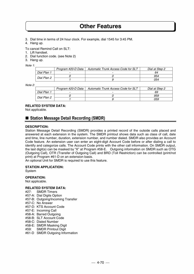
Other Features
4-70
3. Dial time in terms of 24 hour clock. For example, dial 1545 for 3:45 PM.4. Hang up.
To cancel Remind Call on SLT:1. Lift handset.2. Dial function code. (see Note 2)3. Hang up.
Note 1:Program #20-D Data Automatic Trunk Access Code for SLT Dial at Step 2
Dial Plan 1 - - 640 0 954
Dial Plan 21 9 054
Note 2:Program #20-D Data Automatic Trunk Access Code for SLT Dial at Step 2
Dial Plan 1 - - 690 0 959
Dial Plan 21 9 059
RELATED SYSTEM DATA:Not applicable.
!!!! Station Message Detail Recording (SMDR)
DESCRIPTION:Station Message Detail Recording (SMDR) provides a printed record of the outside calls placed andanswered at each extension in the system. The SMDR printout shows data such as class of call, dateand time, line number, duration, extension number, and number dialed. SMDR also provides an AccountCode feature. An extension user can enter an eight-digit Account Code before or after dialing a call toidentify and categorize calls. The Account Code prints with the other call information. On SMDR output,the last digit(s) can be masked by “X” at Program #58-E. Outgoing information on SMDR such as OTG(Outgoing Call), OTR (Transfer of Outgoing Call) and BRD (Toll Restriction) can be controlled (print/notprint) at Program #61-D on an extension basis.An optional Unit for SMDR is required to use this feature.
STATION APPLICATION:System
OPERATION:Not applicable.
RELATED SYSTEM DATA:#27: SMDR Timers#57-A: Dial Digits Option#57-B: Outgoing/Incoming Transfer#57-C: No Answer#57-D: KTS Account Code#57-E: Incoming Call#58-A: Barred Outgoing#58-B: SLT Account Code#58-C: Dialed Number#58-E: SMDR Masking Digit#59: SMDR Printout Digit#61-D SMDR Outgoing Information
Other Features
4-71
!!!! Polarity Reverse Detection (TX-Z 1232/2464)
DESCRIPTION:The system can detect the Polarity Reverse signals sent from public exchange lines. By this feature,following features are controlled.
- Time indication of Trunk line conversation: Start/End- Outgoing call duration time count by SMDR: Start/End- Open the DTMF Receiver- Finish the Conversation on the Trunk-to-Trunk.
STATION APPLICATION:KTS, SLT
OPERATION:Not applicable
RELATED SYSTEM DATA:#01-E: Polarity Reverse Detection#60: Polarity Reverse Detect Time#83-A: Trunk Disconnection when detected polarity reverse
!!!! DISA with Audio Guidance
DESCRIPTION:
The automatic answering machine (customer-provided) can be connected to the system as voiceannounce device for DISA line.Also Endless Tape (customer-provided) can be connected to the system as voice announce device forDISA line. This feature allows incoming calls on DISA lines to be automatically answered by a voicerecorded message.
STATION APPLICATION:System
OPERATION:Refer to DISA (Extension Access) on Page 4-20 and DISA (Trunk-to-Trunk) on Page 4-34.
RELATED SYSTEM DATA:#08-A: Instrument Type#13-D: Voice Announce Device Port
!!!! External Call Forward on DISA
DESCRIPTION:External Call Forward (Trunk to Trunk) allows outside parties calling on the DISA Line to transfer the callto other outside parties automatically when system is set to the External Call Forward Mode. Thedestination of the telephone number must be set on the abbreviated dial No. 99.
STATION APPLICATION:System
OPERATION:To set the External Call Forward Mode (#10 KTS only):1. Press SPK.2. Press ICM key. (TX-Z 824/1232/2464 only) (See Note)3. Press OPAC, dial 70.4. Press SPK.
Other Features
4-72
To cancel the External Call Forward Mode (#10 KTS only):1. Press SPK.2. Press ICM key. (TX-Z 824/1232/2464 only) (See Note)3. Press OPAC, dial 70.4. Press SPK.
Note : If Program #75-D is 0 (No tone), skip Step 2 (TX-Z 824/1232/2464).Refer to DISA (Extension Access) on Page 4-20 and DISA (Trunk-to-Trunk) on Page 4-34 .
Other Features
4-73
RELATED SYSTEM DATA:#03-A: DISA Line#03-B: DISA Line Access#08-A: Instrument Type#31: Trunk-to-Trunk Cut-off Timer Assignment
!!!! One-Touch Feature Access
DESCRIPTION:This feature permits to store the features under the One-Touch, Line or DLS keys so they can be used toaccess the following features instead of dialing/pressing function code in [ ]. See descriptions andoperations of each features for detailed procedure. Loop Key (No. 14) can be assigned only to Linekey which is not defined.
01: Alarm <= [OPAC-50]02: Timer <= [OPAC-51]03: Day/Night Mode <= [SPK-ICM(TX-Z 824/1232/2464 only)-TRFR-#] (See Note)04: Monitor <= [OPAC-FLASH]05: Monitored <= [SPK- ICM(TX-Z 824/1232/2464 only)-OPAC-FLASH] (See Note)06: Recall Trunk Display <= [SPK- ICM(TX-Z 824/1232/2464 only)-OPAC-CHECK] (See Note)07: Repeat Dial key <= [OPAC-1]08: Repeat Dialing (Hurry up) <= [OPAC-2]09: Directory Dialing (Line) <= [DC-6]10: Directory Dialing (ICM) <= [DC-4]11: I-Hold Release <= [SPK- ICM(TX-Z 824/1232/2464 only)-OPAC-3] (See Note)12: Restriction Release <= [OPAC-DC]13: External Call Forward Mode (DISA) <= [OPAC-70]14: Loop Key <= [None]22: Conversation Record (TX-Z 824) <= [CONF-95]23: Conversation Record (TX-Z 1232/2464) <= [CONF-95]24: DSS Console Business Mode (TX-Z 1232/2464) <= [SPK-ICM-OPAC-73]25: DSS Console Room Status Mode (TX-Z 1232/2464) <= [SPK-ICM-OPAC-74]26: DSS Console Wakeup Mode (TX-Z 1232/2464) <= [SPK-ICM-OPAC-75]
Note : If Program #75-D is 0 (No tone), skip pressing ICM (TX-Z 824/1232/2464).
STATION APPLICATION:KTS
Other Features
4-74
OPERATION:To store a feature under a One-Touch or Line key:1. Press SPK.2. Press ICM key. (TX-Z 8241232/2464 only) (See Note 1)3. Press OPAC, dial 4.4. Press a desired One-Touch or Line key.5. Dial feature number (01-26) shown in the previous page..6. Dial ∗.7. Press SPK.
To clear a feature stored on a One-touch or Line key:1. Press SPK.2. Press ICM key. (TX-Z 824/1232/2464 only) (See Note 1)3. Press OPAC, dial 4.4. Press a One-Touch or Line key stored feature.5. Dial 00 to delete a feature stored.6. Dial ∗.7. Press SPK.
To check an feature stored under a One-Touch or Line key:- Do not press SPK key.
1. Press CHECK.2. Press a One-Touch or Line key stored feature.3. The number set feature display.
Note 1: If Program #75-D is 0 (No tone), skip pressing ICM (TX-Z 824/1232/2464).Note 2: One-Touch key No.9 (TX-Z 308) is set as Repeat Dial key initially. To store another feature, clear the feature
first.
RELATED SYSTEM DATA:Not applicable.
!!!! Volume Control
DESCRIPTION:The Volume Control, which is provided with all KTSs, allows easy changes to the following: LCD contraston KTS with LCD, station ringing volume, handset receiver volume, and station speaker volume control.
STATION APPLICATION:KTS
Other Features
4-75
OPERATION:To adjust LCD contrast for KTS with LCD:
- Do not lift handset.1. Press the Vol (up) or Vol (down) to increase/decrease LCD contrast while the phone is idle.
To adjust Speaker Volume:1. Press the Vol (up) or Vol (down) to increase/decrease speaker volume while the phone is handsfree
mode.
To adjust Handset Receiver Volume:1. Press the Vol (up) or Vol (down) to increase/decrease handset receiver volume.
To adjust Ringing Volume:1. Press the Vol (up) or Vol (down) to increase/decrease ringing volume while the phone is ringing or
idle mode.
RELATED SYSTEM DATA:#18-D: Handset Receiver Volume
!!!! DLS Console (TX-Z 824/1232/2464)
DESCRIPTION:DLS(Direct Line Selection) Console has 24 DLS keys. Each DLS key is assigned as Trunk Line orFeature Access key. DLS Console should be connected to KTS with LCD extension.On the TX-Z 824 System, this DLS Console is used as DSS(Direct Station Selection) Console. Each DLSkey is assigned to physical port number accordingly. (Not by extension number which is set inProgram 14.) DLS Console user can call the other extension only pressing DLS key. TX-Z 824 Systemcan connect Maximum 3 DLS Consoles.On the TX-Z 1232/2464 System, Each DLS Console key can be used as Trunk Line or Feature Accesskey. Each DLS key is assigned from Trunk Line number 1 to Trunk Line number 24 on the initialcondition. DLS Console user can assign the unused DLS keys as Feature Access Key. TX-Z 1232System can connect Maximum 8 DLS Consoles. TX-Z 2464 System can connect Maximum 16 DLSConsoles.
STATION APPLICATION:KTS with LCD
OPERATION:
– TX-Z 824 –
1. DSS Call (One-Touch Extension Access)1. Do not Lift Handset.
orLift Handset or Press SPK.
2. Press one of DLS key.
2. Automatic Hold of Trunk Line1. On the Trunk line call.2. Press one of DLS key.
3. Unannounced Transfer1. On the Trunk line call.2. Press one of DLS key.
(Trunk Line is held and the other extension is called.)3. Hang up or press TRFR key.
(Called extension is ringing.)
Other Features
4-76
4. Announced Transfer1. On the Trunk Line call.2. Press one of DLS key.
(Trunk Line is held and the other extension is called.)3. Make announcement.4. Hang up or press TRFR key.
(Trunk Line is transferred.)
– TX-Z 1232/2464 –
To seize the Trunk line:1. Press an idle DLS key.
RELATED SYSTEM DATA:Not applicable.
!!!! Headset Operation
DESCRIPTION:A KTS user can utilize a customer-provided headset in place of the handset. Like using Handsfree, usingthe handset frees up the user's hands for other work. However, Headset Operation provides privacy notavailable from Handsfree. While in the headset mode, the hook switch should be On-Hook condition.To use this facility, system requires optional item as follows;
- Recommended Headset set -- Multi-Purpose-Amplifier (8833-81-00)- Profile (1861-00, 1862-00 or 1863-00)- Cable (8800-01-01 or 8800-00-01)
(All Items are Made by GN Netcom)
STATION APPLICATION:KTS
Other Features
4-77
OPERATION:To answer the Trunk Incoming Call:
1. Press SPK.
To place the Trunk Line outgoing call:1. Press SPK.2. Press an idle Line key.3. Dial telephone number.
To transfer the Trunk line:Refer to "Unannounced Transfer" and "Announced Transfer" operations. But Headset usersubstitutes "Press SPK" for "Hang up" in these operations.
RELATED SYSTEM DATA:#04-E: Headset
!!!! Hotel/Motel Features(TX-Z 1232/2464)" SLT Hold Cancel
DESCRIPTION:The system provides the mode that Single Line Telephones can not use flashing operation. Once thedata “1” is input at Program #64-E, flashing function from Single Line Telephones connected to thesystem is ignored. This feature is useful for prohibiting guest phones’ putting calls on hold.
STATION APPLICATION:SLT
OPERATION:None
RELATED SYSTEM DATA:#64-E: SLT Hooking Operation
" DSS Mode Switching
DESCRIPTION:The extension paired with a DSS console allows the DSS console to indicate extension status in threemodes. Business, Room Status, and Wakeup modes are available.
STATION APPLICATION:KTS
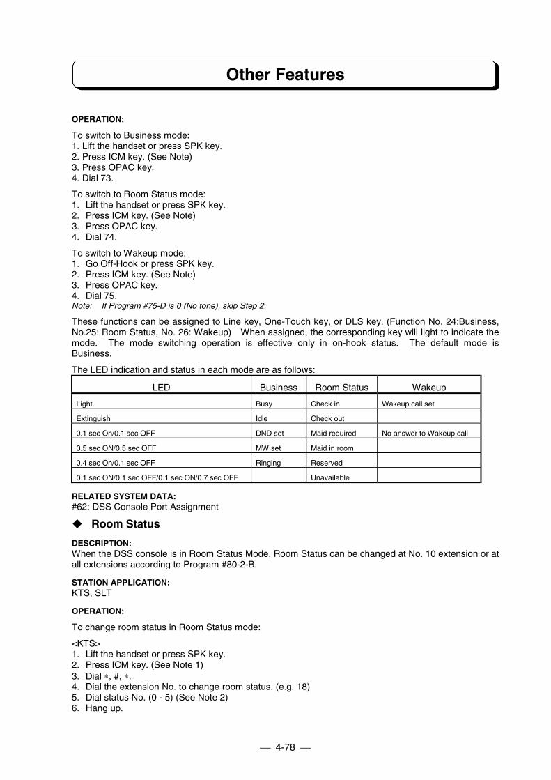
Other Features
4-78
OPERATION:
To switch to Business mode:1. Lift the handset or press SPK key.2. Press ICM key. (See Note)3. Press OPAC key.4. Dial 73.
To switch to Room Status mode:1. Lift the handset or press SPK key.2. Press ICM key. (See Note)3. Press OPAC key.4. Dial 74.
To switch to Wakeup mode:1. Go Off-Hook or press SPK key.2. Press ICM key. (See Note)3. Press OPAC key.4. Dial 75.Note: If Program #75-D is 0 (No tone), skip Step 2.
These functions can be assigned to Line key, One-Touch key, or DLS key. (Function No. 24:Business,No.25: Room Status, No. 26: Wakeup) When assigned, the corresponding key will light to indicate themode. The mode switching operation is effective only in on-hook status. The default mode isBusiness.
The LED indication and status in each mode are as follows:
LED Business Room Status Wakeup
Light Busy Check in Wakeup call set
Extinguish Idle Check out
0.1 sec On/0.1 sec OFF DND set Maid required No answer to Wakeup call
0.5 sec ON/0.5 sec OFF MW set Maid in room
0.4 sec On/0.1 sec OFF Ringing Reserved
0.1 sec ON/0.1 sec OFF/0.1 sec ON/0.7 sec OFF Unavailable
RELATED SYSTEM DATA:#62: DSS Console Port Assignment
" Room Status
DESCRIPTION:When the DSS console is in Room Status Mode, Room Status can be changed at No. 10 extension or atall extensions according to Program #80-2-B.
STATION APPLICATION:KTS, SLT
OPERATION:
To change room status in Room Status mode:
<KTS>1. Lift the handset or press SPK key.2. Press ICM key. (See Note 1)3. Dial ∗, #, ∗.4. Dial the extension No. to change room status. (e.g. 18)5. Dial status No. (0 - 5) (See Note 2)6. Hang up.
Other Features
4-79
<SLT on Dial Plan 1>1. Lift handset.2. Dial 67.3. Dial the extension No. to change room status. (e.g. 18)4. Dial status No. (0 - 5) (See Note 2)5. Hang up.
<SLT on Dial Plan 2>1. Lift handset.2. Dial 067 (967) (See Note 3)3. Dial the extension No. to change room status. (e.g. 18)4. Dial status No. (0 - 5) (See Note 2)5. Hang up.
Note 1: If Program #75-D is 0 (No tone), skip Step 2 (TX-Z 824/1232/2464).Note 2: Status Numbers are as follows:
No. Indication Meaning0 Check In Guest is in the room.1 Maid Required Guest left the room and cleaning is required for Maid.2 Maid In Room Guest left the room and Maid is cleaning the room.3 Check Out The room is vacant, and ready for Check In.4 Reserve The room is reserved5 Unavailable The room is out of order.
Note 3:Program #20-D Data Automatic Trunk Access Code for SLT Dial at Step 2
0 0 9671 9 067
Note 4: “Check In” operation is invalid if the Room Status is “Unavailable”. Change the status to “Check Out “before“Check In” operation.
RELATED SYSTEM DATA:#80-2-B: Room Status
Other Features
4-80
" Call Charge Output to SMDR
DESCRIPTION:When the room status is changed to Maid Required, the system automatically outputs the call charge(total charge) of the associated extension to SMDR (Station Message Detail Recording) reports. Theoutside calls made after Room Status of the extension is set to Check In and until set to Maid Requiredare charged. The call charge after Room Status of the extension is set to Check In and up to the presentcan be output to SMDR manually. The Call Charge data remains and can be output until next Check Inoperation. The dials which match the code stored in Charge Code Table are charged according to thecorresponding charge rate. A maximum of 50 codes (1- 4 digits) can be entered in the Call Charge Table.Optional (charge in one minute increment) or fixed (charge per call) rate is applied on a Trunk line basis.If the total charge exceeds the maximum call charge assigned in Program #98, the system sets DialBlock to prohibit outside calls from that extension.24SMDR-A1 or 24SMCID-A1 is required for SMDR feature.
SMDR Output Example
CLS DATE TIME LINE DURATION ST# DIALED# RING ACCT NO.OTG 30/07/98 14:06:50 01 00:04:09 11 0312344568TOTAL CALL CHARGE TEL NO.: 011 CALL COUNT: 001 TOTAL 00100
Note: The total charge is output with or without a decimal point (for auxiliary currency unit). The possible maximumvalue of total charge is 999999, or 9999.99. If the total charge exceeds the maximum value, the maximumvalue is output.
STATION APPLICATION:KTS, SLT (Depending on Program 80-2-B)
OPERATION:
To output Total Call Charge of an extension manually:
<KTS>1. Lift the handset or press SPK key.2. Press ICM key. (See Note1)3. Dial ∗, #, ∗.4. Dial the extension No. to output the call charge. (e.g. 18)5. Dial 6.6. Hang up.
<SLT on Dial Plan 1>1. Lift handset.2. Dial 67.3. Dial the extension No. to output the call charge. (e.g. 18)4. Dial 6.5. Hang up.
Other Features
4-81
<SLT on Dial Plan 2>1. Lift handset.2. Dial 067 (967) (See Note 2)3. Dial the extension No. to output Call Charge. (e.g. 18)4. Dial 6.5. Hang up.
Note 1: If Program #75-D is 0 (No tone), skip Step 2.Note 2:
Program #20-D Data Automatic Trunk Access Code for SLT Dial at Step 20 0 9671 9 067
RELATED SYSTEM DATA:#80-2-C: Call Charge Format#80-2-B: Room Status#83-B: Optional/Fixed Rate Table Selection#96: Charge Code Table#97: Charge Rate Table#98: Maximum Call Charge
" Dial Block
DESCRIPTION:Dial Block can be set or canceled at Attendant extension (No.10 extension). This feature allows theuser to restrict the guests’ outside calls.
STATION APPLICATION:KTS (No.10 Extension)
OPERATION:To set Dial Block at Attendant extension (No.10 extension):(On-Hook condition)1. Press OPAC key.2. Dial 9 and ∗.3. Dial Password (738).4. Press HOLD key.5. Dial the desired extension No. to set Dial Block (e.g. 12)6. Dial ∗ to accept. (1 short beep tone shall be heard.)7. Dial #.8. Repeat step 5 -7 to set Dial Block to another extension.
orPress HOLD key to exit.
Other Features
4-82
To cancel Dial Block at Attendant extension (No.10 extension):(On-Hook condition)1. Press OPAC key.2. Dial 9 and ∗.3. Dial Password (73738).4. Press HOLD key.5. Dial the desired extension No. to cancel Dial Block (e.g. 12)6. Dial ∗ to accept. (1 short beep tone shall be heard.)7. Dial #.8. Repeat steps 5 -7 to cancel Dial Block for another extension.
orPress HOLD key to exit.
RELATED SYSTEM DATA:#35: Toll Restriction Class Assignment
" Wakeup Call
DESCRIPTION:Wake-up call can be set or cancelled from each Single Line Telephone extensions and the Attendantextension. (No.10 extension). When the time comes and ringing time assigned in Program 80-2-D isover, it recalls the attendant extension until the attendant extension user presses CLEAR key.
STATION APPLICATION:KTS(No.10 Extension), SLT
OPERATION:To set Wakeup Call:<KTS (#10 extension)>(On-Hook condition)1. Press OPAC key.2. Dial 9 and #.3. Dial extension No. (e.g.12)4. Press ∗ to accept.5. Dial Hour and Minute in 24 hours mode.6. Press ∗ to accept. (One short beep tone shall be sent.)7. Return to the idle condition automatically.<SLT>1. Lift handset.2. Dial function code. (see Note 1)3. Dial time in terms of 24 hour clock. For example, dial 1545 for 3:45 PM.4. Hang up.
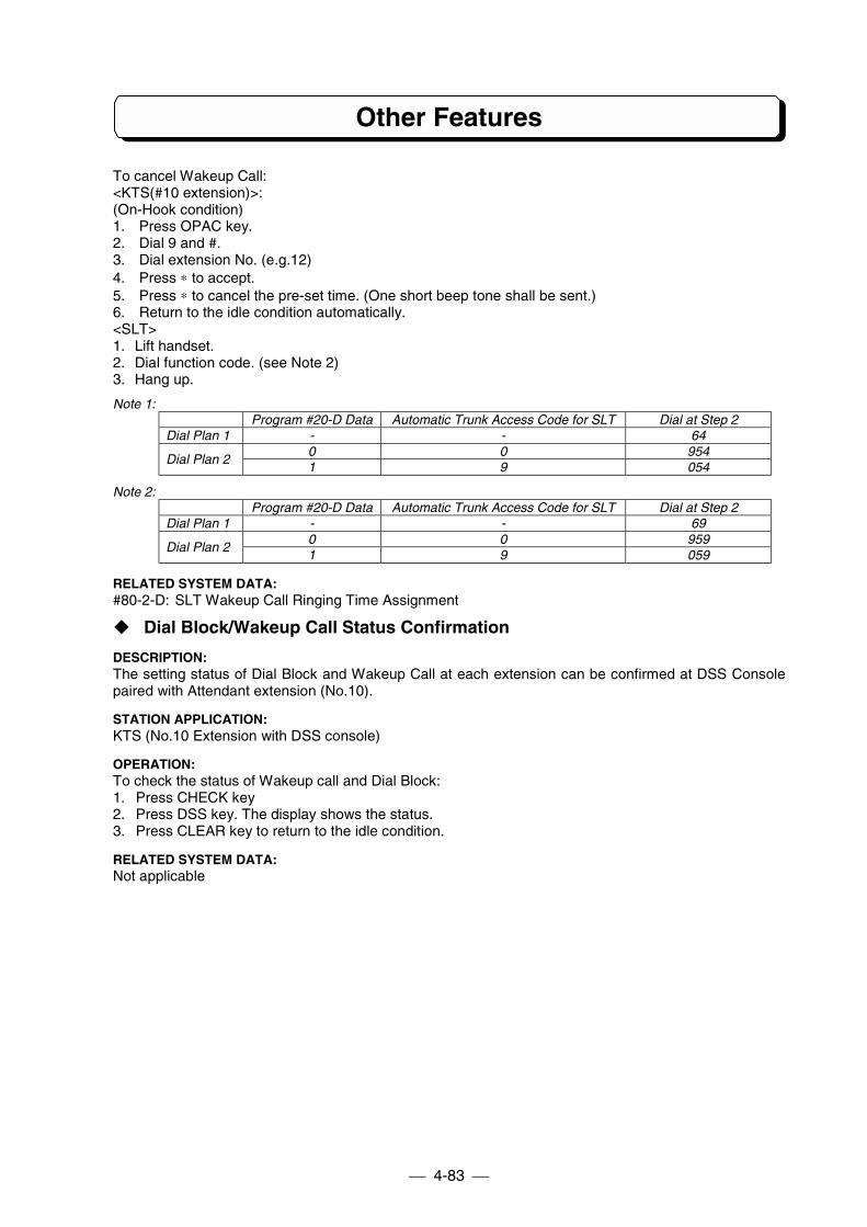
Other Features
4-83
To cancel Wakeup Call:<KTS(#10 extension)>:(On-Hook condition)1. Press OPAC key.2. Dial 9 and #.3. Dial extension No. (e.g.12)4. Press ∗ to accept.5. Press ∗ to cancel the pre-set time. (One short beep tone shall be sent.)6. Return to the idle condition automatically.<SLT>1. Lift handset.2. Dial function code. (see Note 2)3. Hang up.
Note 1:Program #20-D Data Automatic Trunk Access Code for SLT Dial at Step 2
Dial Plan 1 - - 640 0 954
Dial Plan 21 9 054
Note 2:Program #20-D Data Automatic Trunk Access Code for SLT Dial at Step 2
Dial Plan 1 - - 690 0 959
Dial Plan 21 9 059
RELATED SYSTEM DATA:#80-2-D: SLT Wakeup Call Ringing Time Assignment
" Dial Block/Wakeup Call Status Confirmation
DESCRIPTION:The setting status of Dial Block and Wakeup Call at each extension can be confirmed at DSS Consolepaired with Attendant extension (No.10).
STATION APPLICATION:KTS (No.10 Extension with DSS console)
OPERATION:To check the status of Wakeup call and Dial Block:1. Press CHECK key2. Press DSS key. The display shows the status.3. Press CLEAR key to return to the idle condition.
RELATED SYSTEM DATA:Not applicable
Other Features
4-84
" Room Monitor
DESCRIPTION:Room Monitor lets one extension monitor (listen to) the sounds in a room containing another extension.
STATION APPLICATION:KTS, SLT
OPERATION:To activate Room Monitor at monitored extension:<SLT>1. Off-Hook condition. (Busy tone is heard)Note 1: Room Monitor is not available while the SLT is busy on Intercom call, on a Trunk line call, or dialing.Note 2: KTS can be monitored by only KTS in another method. Refer to “Room Monitor” on Page 4-53.
To activate Room Monitor at monitoring extension:<SLT on Dial Plan 1>1. Lift the handset.2. Dial 7.3. Dial the monitored SLT extension No. (Busy tone is heard)4. Dial 2.
<KTS, SLT on Dial Plan 2>1. Lift the handset. (See Note)2. Dial the monitored SLT extension No. (Busy tone is heard)3. Dial 2.Note: If Program #75-D=0 (No tone), press ICM key after lifting handset. (KTS)
To cancel Room Monitor at monitored and monitoring extension:1. Replace the handset.
RELATED SYSTEM DATA:#19-D: Room Monitor
" Attendant Call
DESCRIPTION:Attendant Call allows extension users to call attendant extension by dialing a single digit.
STATION APPLICATION:KTS, SLT
OPERATION:To place an Attendant Call : (#78-D=1)<KTS>1. Press ICM key.2. Dial 0.
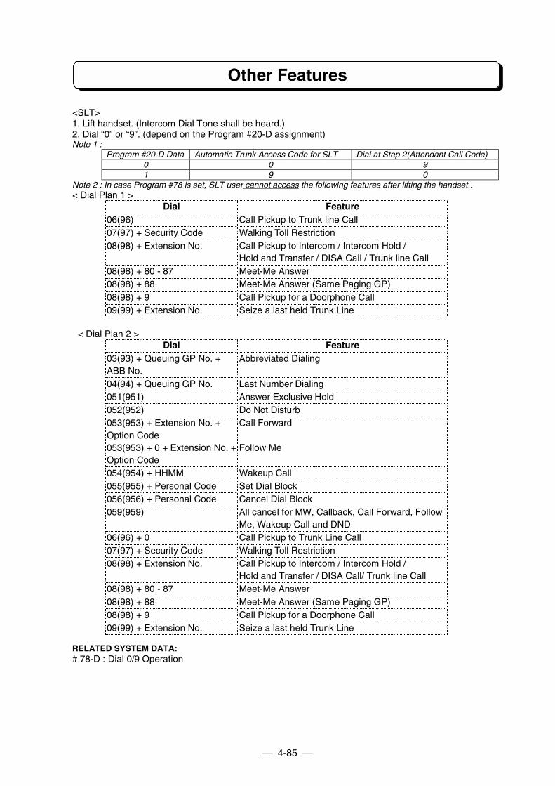
Other Features
4-85
<SLT>1. Lift handset. (Intercom Dial Tone shall be heard.)2. Dial “0” or “9”. (depend on the Program #20-D assignment)Note 1 :
Program #20-D Data Automatic Trunk Access Code for SLT Dial at Step 2(Attendant Call Code)0 0 91 9 0
Note 2 : In case Program #78 is set, SLT user cannot access the following features after lifting the handset..< Dial Plan 1 >
Dial Feature06(96) Call Pickup to Trunk line Call07(97) + Security Code Walking Toll Restriction08(98) + Extension No. Call Pickup to Intercom / Intercom Hold /
Hold and Transfer / DISA Call / Trunk line Call08(98) + 80 - 87 Meet-Me Answer08(98) + 88 Meet-Me Answer (Same Paging GP)08(98) + 9 Call Pickup for a Doorphone Call09(99) + Extension No. Seize a last held Trunk Line
< Dial Plan 2 >Dial Feature
03(93) + Queuing GP No. + Abbreviated DialingABB No.04(94) + Queuing GP No. Last Number Dialing051(951) Answer Exclusive Hold052(952) Do Not Disturb053(953) + Extension No. + Call ForwardOption Code053(953) + 0 + Extension No. + Follow MeOption Code054(954) + HHMM Wakeup Call055(955) + Personal Code Set Dial Block056(956) + Personal Code Cancel Dial Block059(959) All cancel for MW, Callback, Call Forward, Follow
Me, Wakeup Call and DND06(96) + 0 Call Pickup to Trunk Line Call07(97) + Security Code Walking Toll Restriction08(98) + Extension No. Call Pickup to Intercom / Intercom Hold /
Hold and Transfer / DISA Call/ Trunk line Call08(98) + 80 - 87 Meet-Me Answer08(98) + 88 Meet-Me Answer (Same Paging GP)08(98) + 9 Call Pickup for a Doorphone Call09(99) + Extension No. Seize a last held Trunk Line
RELATED SYSTEM DATA:# 78-D : Dial 0/9 Operation
Other Features
4-86
!!!! Single Line Extension Dial Tone
DESCRIPTION:Single Line Telephone Extension Dial Tone is selectable from either Continuous Tone or 0.3sec. ON /0.2sec. OFF Tone by programming. This assignment is on a system basis. Single Line Extension DialTone for all connected SLTs shall be defined according to Program #78-B
STATION APPLICATION:SLT
OPERATION:None
RELATED SYSTEM DATA#78-B: SLT Dial Tone
!!!! Special User PasswordDESCRIPTION:Following Programs can be entered by using “Special User Password” instead of “System ProgrammingPassword”. “Special User Password” is a 10 digit (8737727796) numeric code. The user can, however,change the password for any other 10 digit code by system programming. The following programs can beaccessed :
- Program #42 : Walking Toll Restriction Security Code- Program #43 : Toll Restriction Class Assignment on Security Code- Program #46 : DISA Security Code- Program #47 : DISA Security Code Extension Assignment- Program #48 : DISA Toll Restriction Class- Program #99 : Program Buffer Cancellation
STATION APPLICATION:KTS (only No.10 extension)
OPERATION:To Enter Programming Mode :1. On Hook Condition.2. Press OPAC key.3. Dial #, ∗, #, ∗ .4. Dial Password. (8737727796)5. Press HOLD key.Note: Upon entering Programming Mode, if the Program address for which access is restricted is keyed, the
display indication will go blank, pressing the # key will return the display to normal programming mode.
Other Features
4-87
To exit Programming Mode :1. Return to “Program No. Input” mode.2. Press HOLD key.
RELATED SYSTEM DATA:None
!!!! Voice Mail Connection (TX-Z 824/1232/2464)
DESCRIPTION:The TX-Z System is compatible with NVM-2 and NVM-22 Nitsuko Voice Mail Systems. This featureprovides telephone users with comprehensive Voice Messaging and Auto Attendant capabilities.Voice Mail Interface Units are also required for Voice Mail Connection. The 408M/208E/008E/408U/008Uunits connected Voice Mail must be mounted new version of sub-CPU (MB89626RPF-G-615 or 616).
STATION APPLICATION:Not Applicable
OPERATION:Refer to NVM User’s Guide.
RELATED SYSTEM DATA:#85: NVM Connection Port (TX-Z 1232/2464)#65: NVM Connection Port (TX-Z 824)
!!!! Caller-ID
DESCRIPTION:Refer to Caller-ID Unit in Part 7-1 in this manual.
!!!! VAU (TX-Z 1232/2464)
DESCRIPTION:Refer to Voice Announce/Record Unit in Part 7-3 in this manual.
!!!! DUD (TX-Z 308)
DESCRIPTION:Refer to FAX Transfer/DUD Unit in Part 7-2 in this manual.
!!!! FAX Transfer (TX-Z 308)
DESCRIPTION:Refer to FAX Transfer/DUD Unit in Part 7-2 in this manual.
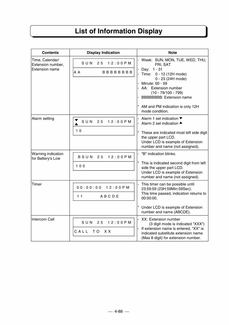
List of Information Display
4-88
Contents Display Indication Note
Time, Calendar/Extension number,Extension name
# # S U N # 2 5 # 1 2 : 0 0 P M
A A # # # # # # B B B B B B B B
- Week: SUN, MON, TUE, WED, THU,FRI, SAT
- Day: 1 - 31- Time: 0 - 12 (12H mode)
0 - 23 (24H mode)- Minute: 00 - 59- AA: Extension number
(10 - 79/100 - 799)- BBBBBBBB: Extension name
* AM and PM indication is only 12Hmode condition.
Alarm setting# # S U N # 2 5 # 1 2 : 0 0 P M
1 0 # # # # # # # # # # # # # #
- Alarm 1 set indication- Alarm 2 set indication
* These are indicated most left side digitthe upper part LCD.Under LCD is example of Extensionnumber and name (not assigned).
Warning indicationfor Battery's Low # B S U N # 2 5 # 1 2 : 0 0 P M
1 0 0 # # # # # # # # # # # # #
- "B" indication blinks.
* This is indicated second digit from leftside the upper part LCD.Under LCD is example of Extensionnumber and name (not assigned).
Timer0 0 : 0 0 : 0 0 # 1 2 : 0 0 P M
1 1 # # # # A B C D E # # #
- This timer can be possible until23:59:59 (23H:59Min:59Sec).This time passed, indication returns to00:00:00.
* Under LCD is example of Extensionnumber and name (ABCDE).
Intercom Call# # S U N # 2 5 # 1 2 : 0 0 P M
C A L L # T O # X X # # # # # #
- XX: Extension number(3 digit mode is indicated "XXX")
- If extension name is entered, "XX" isindicated substitute extension name(Max 8 digit) for extension number.
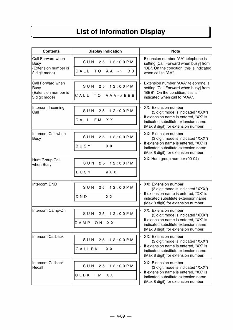
List of Information Display
4-89
Contents Display Indication Note
Call Forward whenBusy(Extension number is2 digit mode)
# # S U N # 2 5 # 1 2 : 0 0 P M
C A L L # T O # A A # - > # B B
- Extension number "AA" telephone issetting [Call Forward when busy] from"BB". On the condition, this is indicatedwhen call to "AA".
Call Forward whenBusy(Extension number is3 digit mode)
# # S U N # 2 5 # 1 2 : 0 0 P M
C A L L # T O # A A A - > B B B
- Extension number "AAA" telephone issetting [Call Forward when busy] from"BBB". On the condition, this isindicated when call to "AAA".
Intercom IncomingCall # # S U N # 2 5 # 1 2 : 0 0 P M
C A L L # F M # X X # # # # # #
- XX: Extension number(3 digit mode is indicated "XXX")
- If extension name is entered, "XX" isindicated substitute extension name(Max 8 digit) for extension number.
Intercom Call whenBusy # # S U N # 2 5 # 1 2 : 0 0 P M
B U S Y # # # # X X # # # # # #
- XX: Extension number(3 digit mode is indicated "XXX")
- If extension name is entered, "XX" isindicated substitute extension name(Max 8 digit) for extension number.
Hunt Group Callwhen Busy # # S U N # 2 5 # 1 2 : 0 0 P M
B U S Y # # # # # X X # # # # #
- XX: Hunt group number (00-04)
Intercom DND# # S U N # 2 5 # 1 2 : 0 0 P M
D N D # # # # # X X # # # # # #
- XX: Extension number(3 digit mode is indicated "XXX")
- If extension name is entered, "XX" isindicated substitute extension name(Max 8 digit) for extension number.
Intercom Camp-On# # S U N # 2 5 # 1 2 : 0 0 P M
C A M P # O N # X X # # # # # #
- XX: Extension number(3 digit mode is indicated "XXX")
- If extension name is entered, "XX" isindicated substitute extension name(Max 8 digit) for extension number.
Intercom Callback# # S U N # 2 5 # 1 2 : 0 0 P M
C A L L B K # # X X # # # # # #
- XX: Extension number(3 digit mode is indicated "XXX")
- If extension name is entered, "XX" isindicated substitute extension name(Max 8 digit) for extension number.
Intercom CallbackRecall # # S U N # 2 5 # 1 2 : 0 0 P M
C L B K # F M # X X # # # # # #
- XX: Extension number(3 digit mode is indicated "XXX")
- If extension name is entered, "XX" isindicated substitute extension name(Max 8 digit) for extension number.
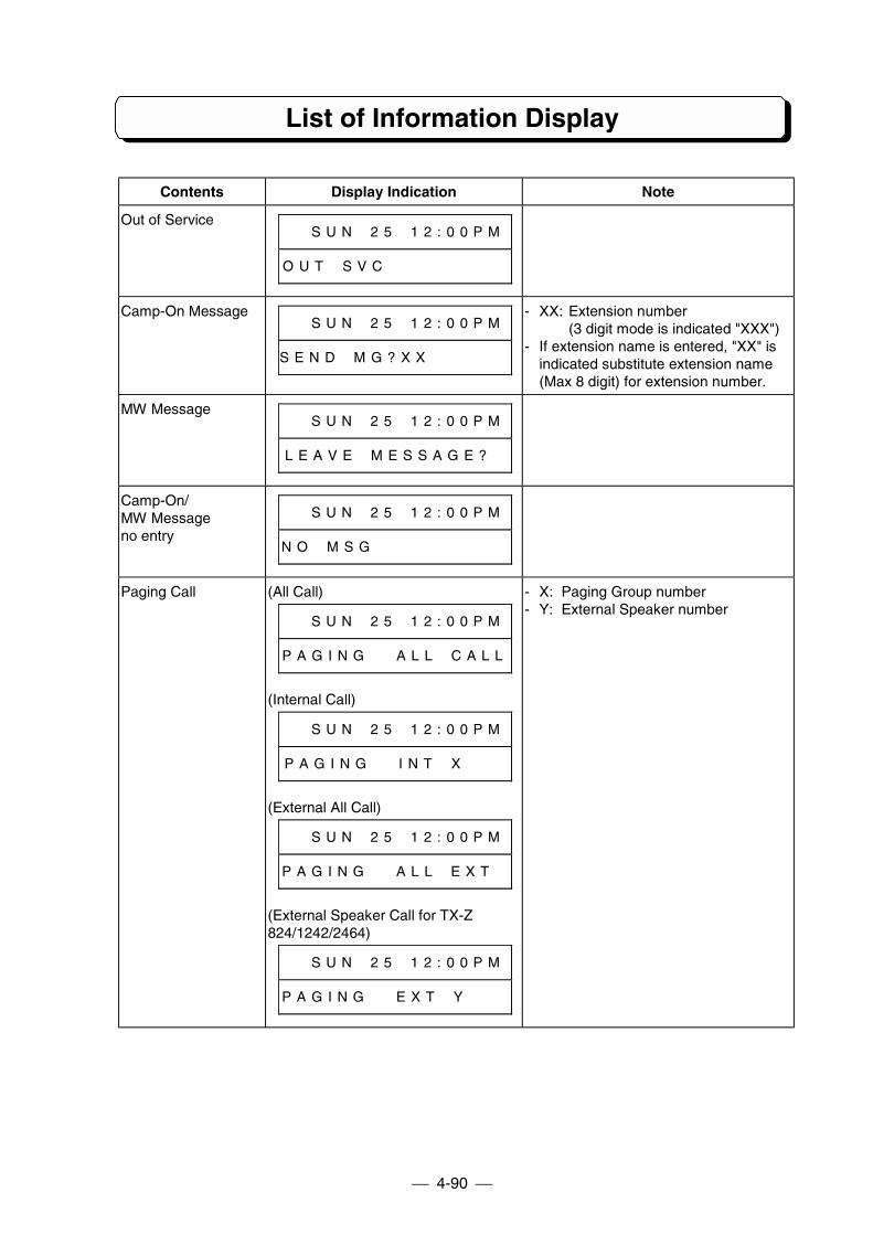
List of Information Display
4-90
Contents Display Indication Note
Out of Service# # S U N # 2 5 # 1 2 : 0 0 P M
O U T # S V C # # # # # # # # #
Camp-On Message# # S U N # 2 5 # 1 2 : 0 0 P M
S E N D # M G ? X X # # # # # #
- XX: Extension number(3 digit mode is indicated "XXX")
- If extension name is entered, "XX" isindicated substitute extension name(Max 8 digit) for extension number.
MW Message# # S U N # 2 5 # 1 2 : 0 0 P M
L E A V E # M E S S A G E ? #
Camp-On/MW Messageno entry
# # S U N # 2 5 # 1 2 : 0 0 P M
N O # M S G # # # # # # # # # #
Paging Call (All Call)
# # S U N # 2 5 # 1 2 : 0 0 P M
P A G I N G # # A L L # C A L L
(Internal Call)
# # S U N # 2 5 # 1 2 : 0 0 P M
P A G I N G # # I N T # X # # #
(External All Call)
# # S U N # 2 5 # 1 2 : 0 0 P M
P A G I N G # # A L L # E X T #
(External Speaker Call for TX-Z824/1242/2464)
# # S U N # 2 5 # 1 2 : 0 0 P M
P A G I N G # # E X T # Y # # #
- X: Paging Group number- Y: External Speaker number
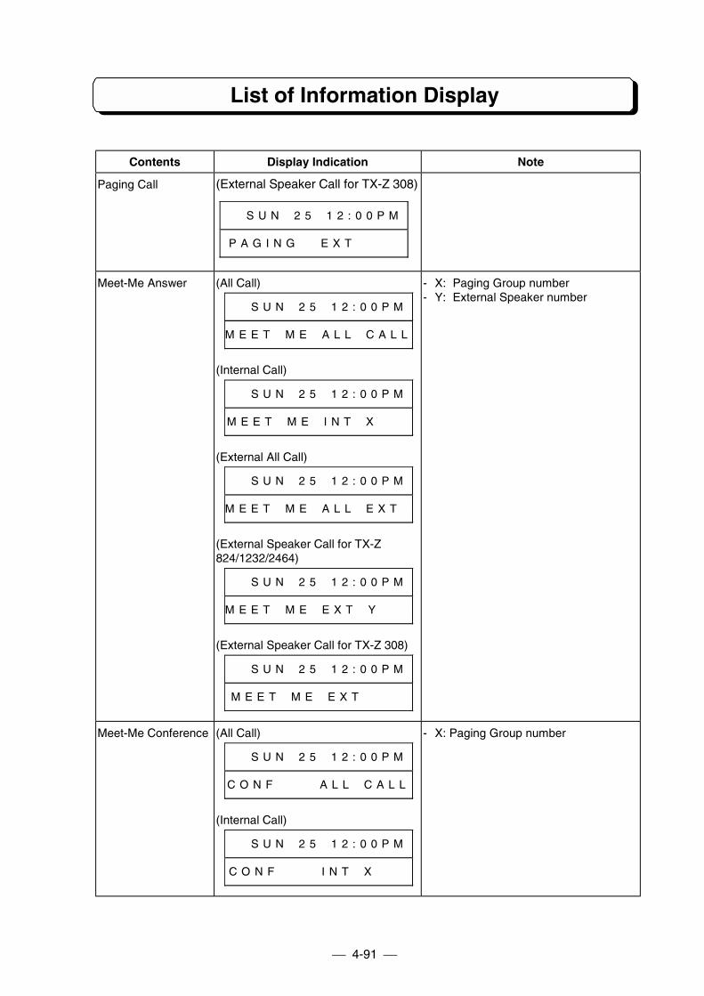
List of Information Display
4-91
Contents Display Indication Note
Paging Call (External Speaker Call for TX-Z 308)
# # S U N # 2 5 # 1 2 : 0 0 P M
P A G I N G # # E X T # # # #
Meet-Me Answer (All Call)
# # S U N # 2 5 # 1 2 : 0 0 P M
M E E T # M E # A L L # C A L L
(Internal Call)
# # S U N # 2 5 # 1 2 : 0 0 P M
M E E T # M E # I N T # X # # #
(External All Call)
# # S U N # 2 5 # 1 2 : 0 0 P M
M E E T # M E # A L L # E X T #
(External Speaker Call for TX-Z824/1232/2464)
# # S U N # 2 5 # 1 2 : 0 0 P M
M E E T # M E # E X T # Y # # #
(External Speaker Call for TX-Z 308)
# # S U N # 2 5 # 1 2 : 0 0 P M
M E E T # M E # E X T # # # #
- X: Paging Group number- Y: External Speaker number
Meet-Me Conference (All Call)
# # S U N # 2 5 # 1 2 : 0 0 P M
C O N F # # # # A L L # C A L L
(Internal Call)
# # S U N # 2 5 # 1 2 : 0 0 P M
C O N F # # # # I N T # X # # #
- X: Paging Group number
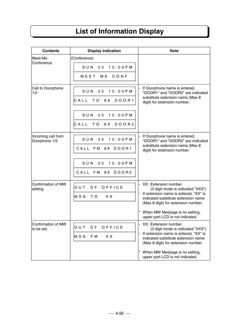
List of Information Display
4-92
Contents Display Indication Note
Meet-MeConference
(Conference)
# # S U N # 2 5 # 1 2 : 0 0 P M
M E E T # M E # C O N F
Call to Doorphone1/2 # # S U N # 2 5 # 1 2 : 0 0 P M
C A L L # T O # 8 8 # D O O R 1
# # S U N # 2 5 # 1 2 : 0 0 P M
C A L L # T O # 8 9 # D O O R 2
- If Doorphone name is entered,"DOOR1" and "DOOR2" are indicatedsubstitute extension name (Max 8digit) for extension number.
Incoming call fromDoorphone 1/2 # # S U N # 2 5 # 1 2 : 0 0 P M
C A L L # F M # 8 8 # D O O R 1
# # S U N # 2 5 # 1 2 : 0 0 P M
C A L L # F M # 8 9 # D O O R 2
- If Doorphone name is entered,"DOOR1" and "DOOR2" are indicatedsubstitute extension name (Max 8digit) for extension number.
Confirmation of MWsetting O U T # O F # O F F I C E # # #
M S G # T O # # X X # # # # # #
- XX: Extension number(3 digit mode is indicated "XXX")
- If extension name is entered, "XX" isindicated substitute extension name(Max 8 digit) for extension number.
* When MW Message is no setting,upper part LCD is not indicated.
Confirmation of MWto be set O U T # O F # O F F I C E # # #
M S G # F M # # X X # # # # # #
- XX: Extension number(3 digit mode is indicated "XXX")
- If extension name is entered, "XX" isindicated substitute extension name(Max 8 digit) for extension number.
* When MW Message is no setting,upper part LCD is not indicated.
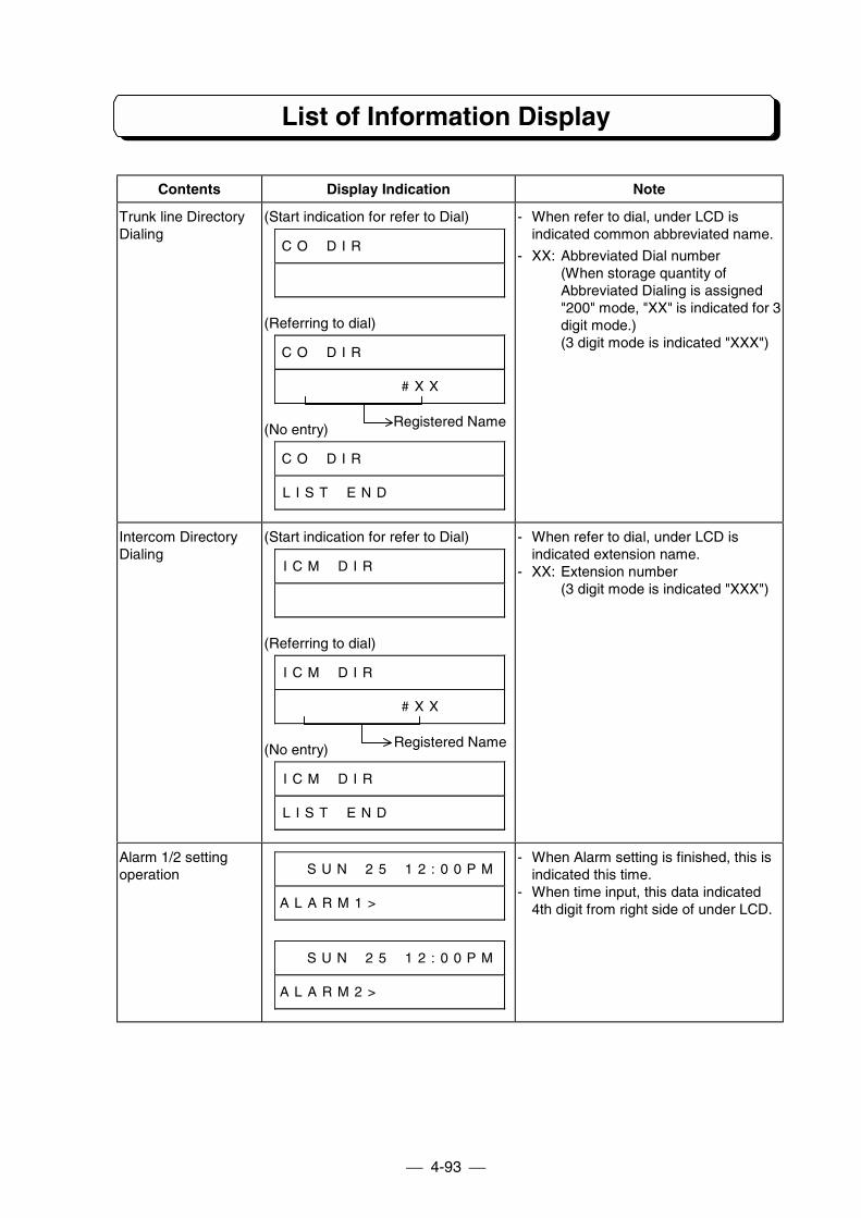
List of Information Display
4-93
Contents Display Indication Note
Trunk line DirectoryDialing
(Start indication for refer to Dial)
C O # D I R # # # # # # # # # #
(Referring to dial)
C O # D I R # # # # # # # # # #
# # # # # # # # # # X X # # # #
(No entry)
C O # D I R # # # # # # # # # #
L I S T # E N D # # # # # # # #
- When refer to dial, under LCD isindicated common abbreviated name.
- XX: Abbreviated Dial number(When storage quantity ofAbbreviated Dialing is assigned"200" mode, "XX" is indicated for 3digit mode.)(3 digit mode is indicated "XXX")
Intercom DirectoryDialing
(Start indication for refer to Dial)
I C M # D I R # # # # # # # # #
(Referring to dial)
I C M # D I R # # # # # # # # #
# # # # # # # # # # X X # # # #
(No entry)
I C M # D I R # # # # # # # # #
L I S T # E N D # # # # # # # #
- When refer to dial, under LCD isindicated extension name.
- XX: Extension number(3 digit mode is indicated "XXX")
Alarm 1/2 settingoperation # # S U N # 2 5 # 1 2 : 0 0 P M
A L A R M 1 > # # # # # # # # #
# # S U N # 2 5 # 1 2 : 0 0 P M
A L A R M 2 > # # # # # # # # #
- When Alarm setting is finished, this isindicated this time.
- When time input, this data indicated4th digit from right side of under LCD.
Registered Name
Registered Name
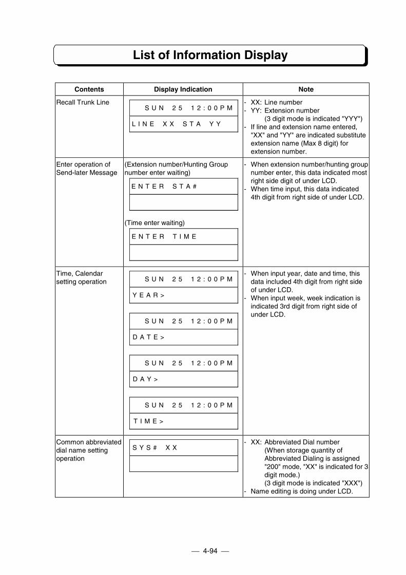
List of Information Display
4-94
Contents Display Indication Note
Recall Trunk Line# # S U N # 2 5 # 1 2 : 0 0 P M
L I N E # X X # S T A # Y Y # #
- XX: Line number- YY: Extension number
(3 digit mode is indicated "YYY")- If line and extension name entered,
"XX" and "YY" are indicated substituteextension name (Max 8 digit) forextension number.
Enter operation ofSend-later Message
(Extension number/Hunting Groupnumber enter waiting)
E N T E R # S T A # # # # # # #
(Time enter waiting)
E N T E R # T I M E # # # # # #
- When extension number/hunting groupnumber enter, this data indicated mostright side digit of under LCD.
- When time input, this data indicated4th digit from right side of under LCD.
Time, Calendarsetting operation # # S U N # 2 5 # 1 2 : 0 0 P M
Y E A R > # # # # # # # # # # #
# # S U N # 2 5 # 1 2 : 0 0 P M
D A T E > # # # # # # # # # # #
# # S U N # 2 5 # 1 2 : 0 0 P M
D A Y > # # # # # # # # # # # #
# # S U N # 2 5 # 1 2 : 0 0 P M
T I M E > # # # # # # # # # # #
- When input year, date and time, thisdata included 4th digit from right sideof under LCD.
- When input week, week indication isindicated 3rd digit from right side ofunder LCD.
Common abbreviateddial name settingoperation
S Y S # # X X # # # # # # # # #- XX: Abbreviated Dial number
(When storage quantity ofAbbreviated Dialing is assigned"200" mode, "XX" is indicated for 3digit mode.)(3 digit mode is indicated "XXX")
- Name editing is doing under LCD.
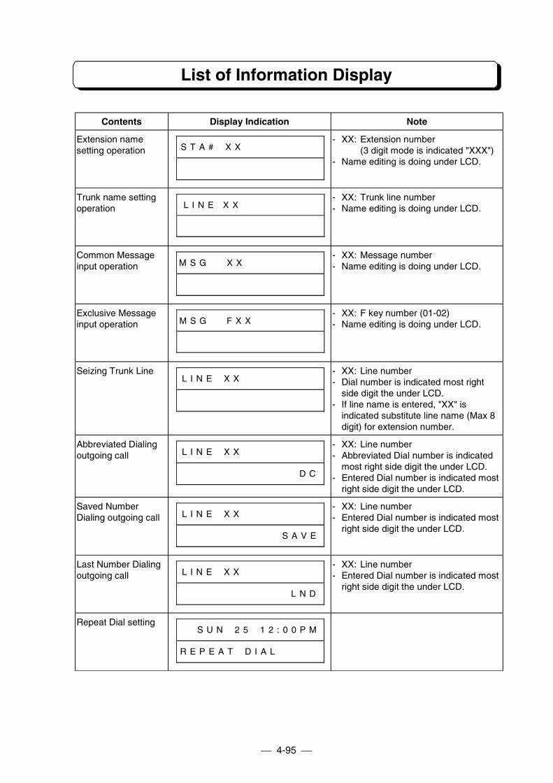
List of Information Display
4-95
Contents Display Indication Note
Extension namesetting operation S T A # # X X # # # # # # # # #
- XX: Extension number(3 digit mode is indicated "XXX")
- Name editing is doing under LCD.
Trunk name settingoperation L I N E X X # # # # # # # # #
- XX: Trunk line number- Name editing is doing under LCD.
Common Messageinput operation M S G # # X X # # # # # # # # #
- XX: Message number- Name editing is doing under LCD.
Exclusive Messageinput operation M S G # # F X X # # # # # # # #
- XX: F key number (01-02)- Name editing is doing under LCD.
Seizing Trunk LineL I N E # X X # # # # # # # # #
- XX: Line number- Dial number is indicated most right
side digit the under LCD.- If line name is entered, "XX" is
indicated substitute line name (Max 8digit) for extension number.
Abbreviated Dialingoutgoing call L I N E # X X # # # # # # # # #
# # # # # # # # # # # # # # D C
- XX: Line number- Abbreviated Dial number is indicated
most right side digit the under LCD.- Entered Dial number is indicated most
right side digit the under LCD.
Saved NumberDialing outgoing call L I N E # X X # # # # # # # # #
# # # # # # # # # # # # S A V E
- XX: Line number- Entered Dial number is indicated most
right side digit the under LCD.
Last Number Dialingoutgoing call L I N E # X X # # # # # # # # #
# # # # # # # # # # # # # L N D
- XX: Line number- Entered Dial number is indicated most
right side digit the under LCD.
Repeat Dial setting# # S U N # 2 5 # 1 2 : 0 0 P M
R E P E A T # D I A L # # # # #
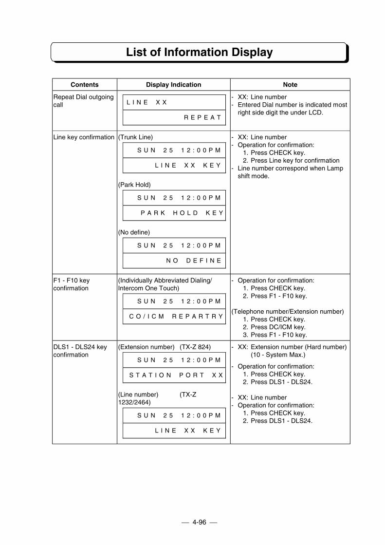
List of Information Display
4-96
Contents Display Indication Note
Repeat Dial outgoingcall L I N E # X X # # # # # # # # #
# # # # # # # # # # R E P E A T
- XX: Line number- Entered Dial number is indicated most
right side digit the under LCD.
Line key confirmation (Trunk Line)
# # S U N # 2 5 # 1 2 : 0 0 P M
# # # # # L I N E # X X # K E Y
(Park Hold)
# # S U N # 2 5 # 1 2 : 0 0 P M
# # # P A R K # H O L D # K E Y
(No define)
# # S U N # 2 5 # 1 2 : 0 0 P M
# # # # # # # N O # D E F I N E
- XX: Line number- Operation for confirmation:
1. Press CHECK key.2. Press Line key for confirmation
- Line number correspond when Lampshift mode.
F1 - F10 keyconfirmation
(Individually Abbreviated Dialing/Intercom One Touch)
# # S U N # 2 5 # 1 2 : 0 0 P M
# C O / I C M # R E P A R T R Y
- Operation for confirmation:1. Press CHECK key.2. Press F1 - F10 key.
(Telephone number/Extension number)1. Press CHECK key.2. Press DC/ICM key.3. Press F1 - F10 key.
DLS1 - DLS24 keyconfirmation
(Extension number) (TX-Z 824)
# # S U N # 2 5 # 1 2 : 0 0 P M
# S T A T I O N # P O R T # X X
(Line number) (TX-Z1232/2464)
# # S U N # 2 5 # 1 2 : 0 0 P M
# # # # # L I N E # X X # K E Y
- XX: Extension number (Hard number)(10 - System Max.)
- Operation for confirmation:1. Press CHECK key.2. Press DLS1 - DLS24.
- XX: Line number- Operation for confirmation:
1. Press CHECK key.2. Press DLS1 - DLS24.
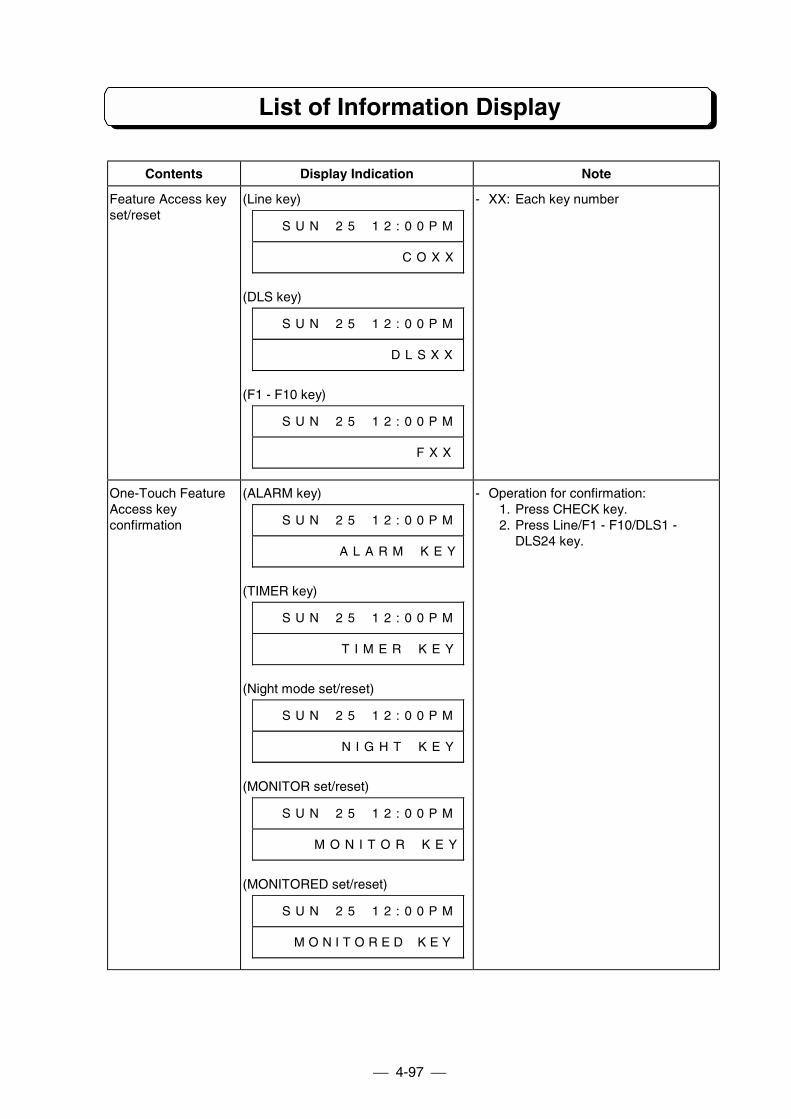
List of Information Display
4-97
Contents Display Indication Note
Feature Access keyset/reset
(Line key)
# # S U N # 2 5 # 1 2 : 0 0 P M
# # # # # # # # # # # # C O X X
(DLS key)
# # S U N # 2 5 # 1 2 : 0 0 P M
# # # # # # # # # # # D L S X X
(F1 - F10 key)
# # S U N # 2 5 # 1 2 : 0 0 P M
# # # # # # # # # # # # # F X X
- XX: Each key number
One-Touch FeatureAccess keyconfirmation
(ALARM key)
# # S U N # 2 5 # 1 2 : 0 0 P M
# # # # # # # A L A R M # K E Y
(TIMER key)
# # S U N # 2 5 # 1 2 : 0 0 P M
# # # # # # # T I M E R # K E Y
(Night mode set/reset)
# # S U N # 2 5 # 1 2 : 0 0 P M
# # # # # # # N I G H T # K E Y
(MONITOR set/reset)
# # S U N # 2 5 # 1 2 : 0 0 P M
# # # # # M O N I T O R # K E Y
(MONITORED set/reset)
# # S U N # 2 5 # 1 2 : 0 0 P M
# # # M O N I T O R E D # K E Y
- Operation for confirmation:1. Press CHECK key.2. Press Line/F1 - F10/DLS1 -
DLS24 key.
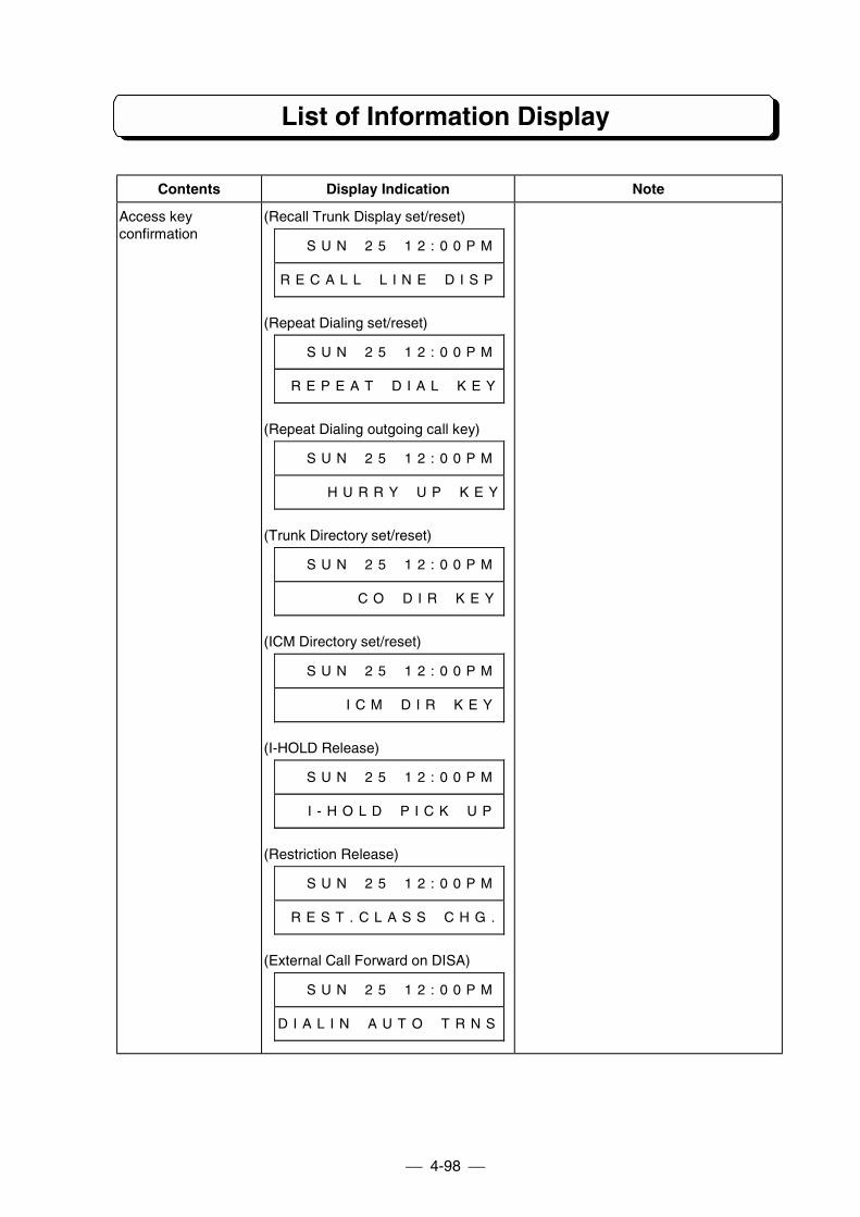
List of Information Display
4-98
Contents Display Indication Note
Access keyconfirmation
(Recall Trunk Display set/reset)
# # S U N # 2 5 # 1 2 : 0 0 P M
R E C A L L # L I N E # D I S P
(Repeat Dialing set/reset)
# # S U N # 2 5 # 1 2 : 0 0 P M
# R E P E A T # D I A L # K E Y
(Repeat Dialing outgoing call key)
# # S U N # 2 5 # 1 2 : 0 0 P M
# # # # H U R R Y # U P # K E Y
(Trunk Directory set/reset)
# # S U N # 2 5 # 1 2 : 0 0 P M
# # # # # # C O # D I R # K E Y
(ICM Directory set/reset)
# # S U N # 2 5 # 1 2 : 0 0 P M
# # # # # I C M # D I R # K E Y
(I-HOLD Release)
# # S U N # 2 5 # 1 2 : 0 0 P M
# # I - H O L D # P I C K # U P
(Restriction Release)
# # S U N # 2 5 # 1 2 : 0 0 P M
# R E S T . C L A S S # C H G .
(External Call Forward on DISA)
# # S U N # 2 5 # 1 2 : 0 0 P M
D I A L I N # A U T O # T R N S
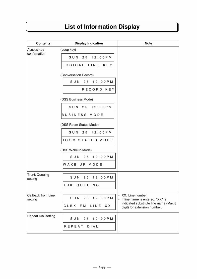
List of Information Display
4-99
Contents Display Indication Note
Access keyconfirmation
(Loop key)
# # S U N # 2 5 # 1 2 : 0 0 P M
L O G I C A L # L I N E # K E Y
(Conversation Record)
# # S U N # 2 5 # 1 2 : 0 0 P M
# R E C O R D K E Y
(DSS Business Mode)
# # S U N # 2 5 # 1 2 : 0 0 P M
B U S I N E S S M O D E
(DSS Room Status Mode)
# # S U N # 2 5 # 1 2 : 0 0 P M
R O O M S T A T U S M O D E
(DSS Wakeup Mode)
# # S U N # 2 5 # 1 2 : 0 0 P M
W A K E U P M O D E
Trunk Queuingsetting # # S U N # 2 5 # 1 2 : 0 0 P M
T R K # Q U E U I N G # # # # #
Callback from Linesetting # # S U N # 2 5 # 1 2 : 0 0 P M
C L B K # F M # L I N E # X X #
- XX: Line number- If line name is entered, "XX" is
indicated substitute line name (Max 8digit) for extension number.
Repeat Dial setting# # S U N # 2 5 # 1 2 : 0 0 P M
R E P E A T # D I A L # # # # #
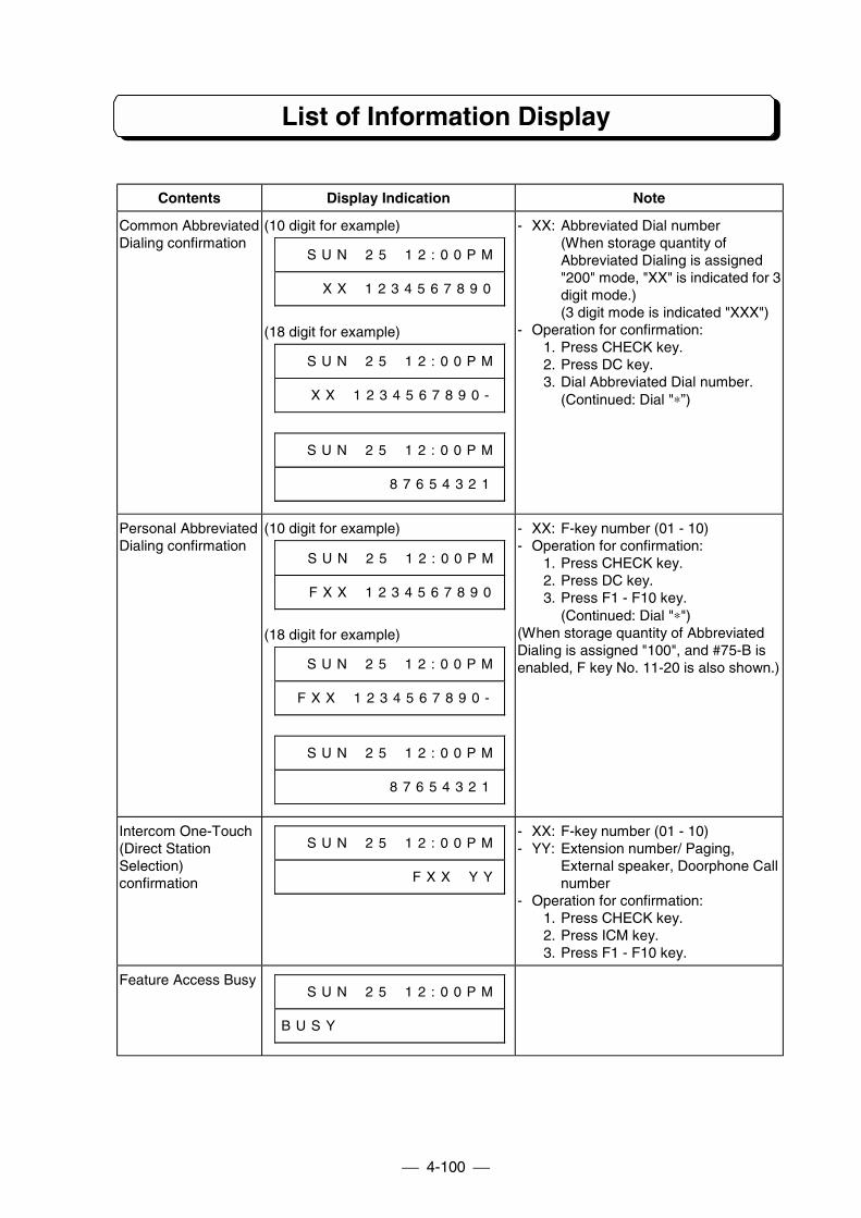
List of Information Display
4-100
Contents Display Indication Note
Common AbbreviatedDialing confirmation
(10 digit for example)
# # S U N # 2 5 # 1 2 : 0 0 P M
# # # X X # 1 2 3 4 5 6 7 8 9 0
(18 digit for example)
# # S U N # 2 5 # 1 2 : 0 0 P M
# # X X # 1 2 3 4 5 6 7 8 9 0 -
# # S U N # 2 5 # 1 2 : 0 0 P M
# # # # # # # # 8 7 6 5 4 3 2 1
- XX: Abbreviated Dial number(When storage quantity ofAbbreviated Dialing is assigned"200" mode, "XX" is indicated for 3digit mode.)(3 digit mode is indicated "XXX")
- Operation for confirmation:1. Press CHECK key.2. Press DC key.3. Dial Abbreviated Dial number.
(Continued: Dial "∗”)
Personal AbbreviatedDialing confirmation
(10 digit for example)
# # S U N # 2 5 # 1 2 : 0 0 P M
# # F X X # 1 2 3 4 5 6 7 8 9 0
(18 digit for example)
# # S U N # 2 5 # 1 2 : 0 0 P M
# F X X # 1 2 3 4 5 6 7 8 9 0 -
# # S U N # 2 5 # 1 2 : 0 0 P M
# # # # # # # # 8 7 6 5 4 3 2 1
- XX: F-key number (01 - 10)- Operation for confirmation:
1. Press CHECK key.2. Press DC key.3. Press F1 - F10 key.
(Continued: Dial "∗")(When storage quantity of AbbreviatedDialing is assigned "100", and #75-B isenabled, F key No. 11-20 is also shown.)
Intercom One-Touch(Direct StationSelection)confirmation
# # S U N # 2 5 # 1 2 : 0 0 P M
# # # # # # # # # # F X X # Y Y
- XX: F-key number (01 - 10)- YY: Extension number/ Paging,
External speaker, Doorphone Callnumber
- Operation for confirmation:1. Press CHECK key.2. Press ICM key.3. Press F1 - F10 key.
Feature Access Busy# # S U N # 2 5 # 1 2 : 0 0 P M
B U S Y # # # # # # # # # # # #
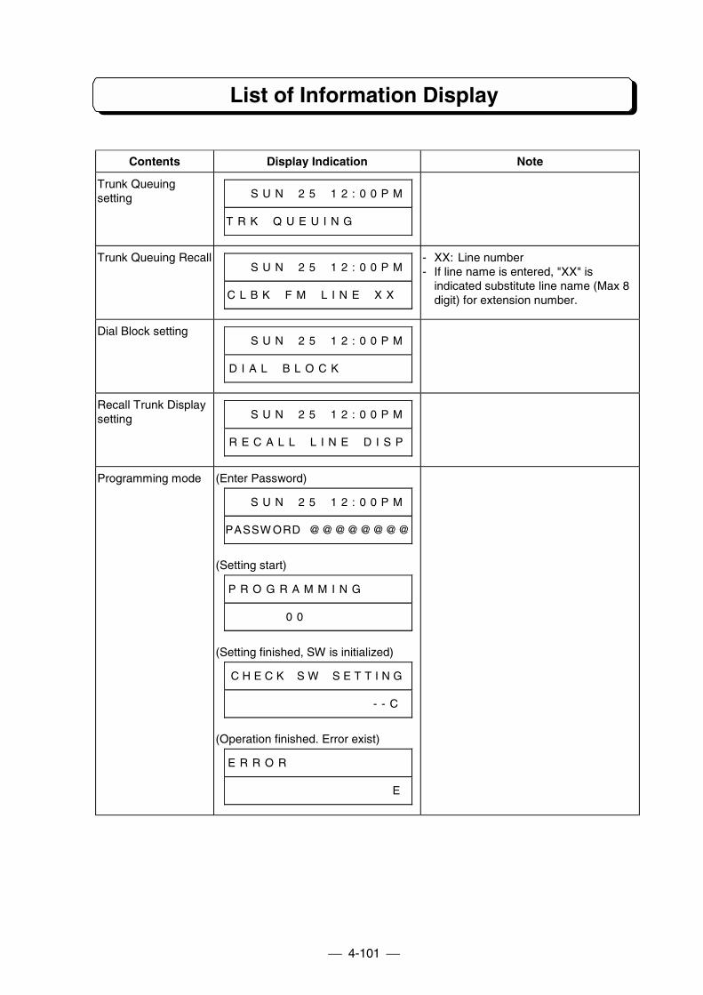
List of Information Display
4-101
Contents Display Indication Note
Trunk Queuingsetting # # S U N # 2 5 # 1 2 : 0 0 P M
T R K # Q U E U I N G # # # # #
Trunk Queuing Recall# # S U N # 2 5 # 1 2 : 0 0 P M
C L B K # F M # L I N E # X X #
- XX: Line number- If line name is entered, "XX" is
indicated substitute line name (Max 8digit) for extension number.
Dial Block setting# # S U N # 2 5 # 1 2 : 0 0 P M
D I A L # B L O C K # # # # # #
Recall Trunk Displaysetting # # S U N # 2 5 # 1 2 : 0 0 P M
R E C A L L # L I N E # D I S P
Programming mode (Enter Password)
# # S U N # 2 5 # 1 2 : 0 0 P M
PASSW ORD#@@@@@@@@
(Setting start)
P R O G R A M M I N G # # # #
# # # # # 0 0 # # # # # # # # #
(Setting finished, SW is initialized)
C H E C K # S W # S E T T I N G
# # # # # # # # # # # # # - - C
(Operation finished. Error exist)
E R R O R # # # # # # # # # # #
# # # # # # # # # # # # # # # E
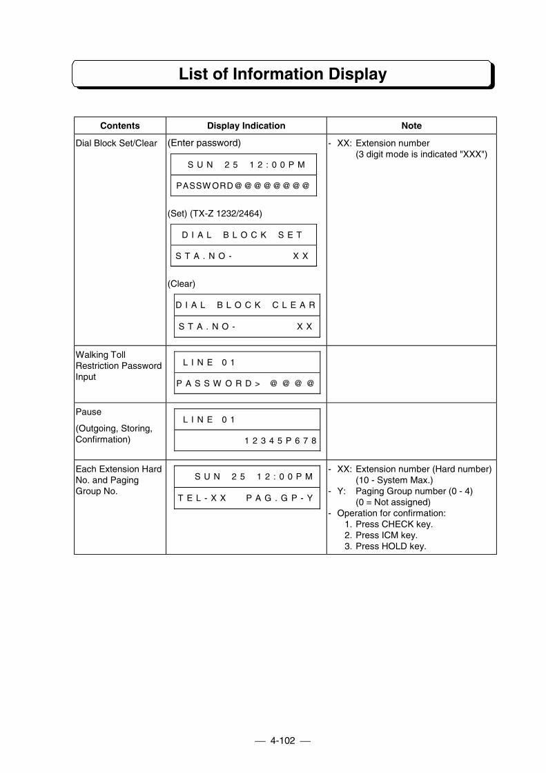
List of Information Display
4-102
Contents Display Indication Note
Dial Block Set/Clear (Enter password)
# # S U N # 2 5 # 1 2 : 0 0 P M
PASSW ORD@@@@@@@@
(Set) (TX-Z 1232/2464)
D I A L # B L O C K # S E T
S T A . N O - # # # # # # # X X
(Clear)
D I A L # B L O C K # C L E A R
S T A . N O - # # # # # # # X X
- XX: Extension number(3 digit mode is indicated "XXX")
Walking TollRestriction PasswordInput
# L I N E 0 1
P A S S W O R D > @ @ @ @
Pause
(Outgoing, Storing,Confirmation)
# L I N E 0 1
1 2 3 4 5 P 6 7 8
Each Extension HardNo. and PagingGroup No.
# # S U N # 2 5 # 1 2 : 0 0 P M
T E L - X X # # P A G . G P - Y
- XX: Extension number (Hard number)(10 - System Max.)
- Y: Paging Group number (0 - 4)(0 = Not assigned)
- Operation for confirmation:1. Press CHECK key.2. Press ICM key.3. Press HOLD key.
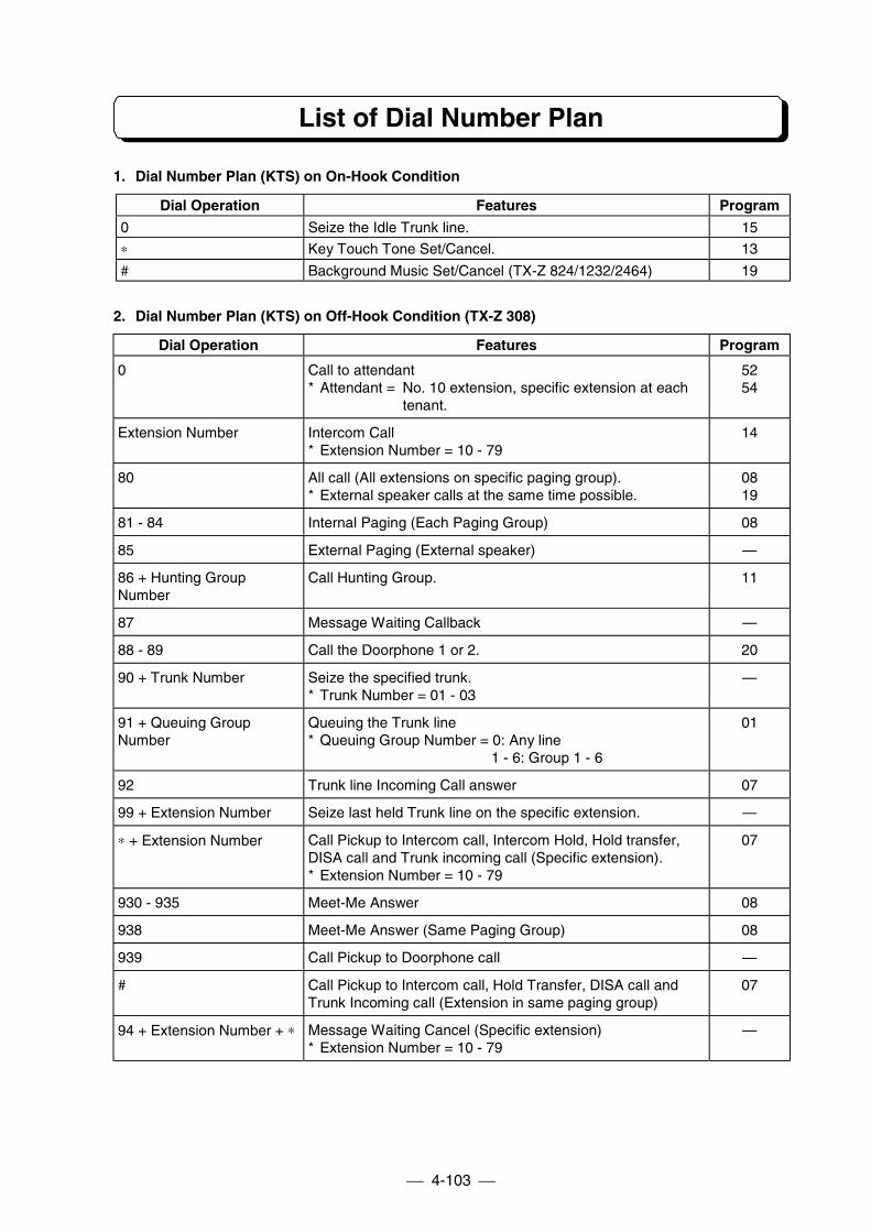
List of Dial Number Plan
4-103
1. Dial Number Plan (KTS) on On-Hook Condition
Dial Operation Features Program
0 Seize the Idle Trunk line. 15
∗ Key Touch Tone Set/Cancel. 13
# Background Music Set/Cancel (TX-Z 824/1232/2464) 19
2. Dial Number Plan (KTS) on Off-Hook Condition (TX-Z 308)
Dial Operation Features Program
0 Call to attendant* Attendant = No. 10 extension, specific extension at each
tenant.
5254
Extension Number Intercom Call* Extension Number = 10 - 79
14
80 All call (All extensions on specific paging group).* External speaker calls at the same time possible.
0819
81 - 84 Internal Paging (Each Paging Group) 08
85 External Paging (External speaker) —
86 + Hunting GroupNumber
Call Hunting Group. 11
87 Message Waiting Callback —
88 - 89 Call the Doorphone 1 or 2. 20
90 + Trunk Number Seize the specified trunk.* Trunk Number = 01 - 03
—
91 + Queuing GroupNumber
Queuing the Trunk line* Queuing Group Number = 0: Any line
1 - 6: Group 1 - 6
01
92 Trunk line Incoming Call answer 07
99 + Extension Number Seize last held Trunk line on the specific extension. —
∗ + Extension Number Call Pickup to Intercom call, Intercom Hold, Hold transfer,DISA call and Trunk incoming call (Specific extension).* Extension Number = 10 - 79
07
930 - 935 Meet-Me Answer 08
938 Meet-Me Answer (Same Paging Group) 08
939 Call Pickup to Doorphone call —
# Call Pickup to Intercom call, Hold Transfer, DISA call andTrunk Incoming call (Extension in same paging group)
07
94 + Extension Number + ∗ Message Waiting Cancel (Specific extension)* Extension Number = 10 - 79
—
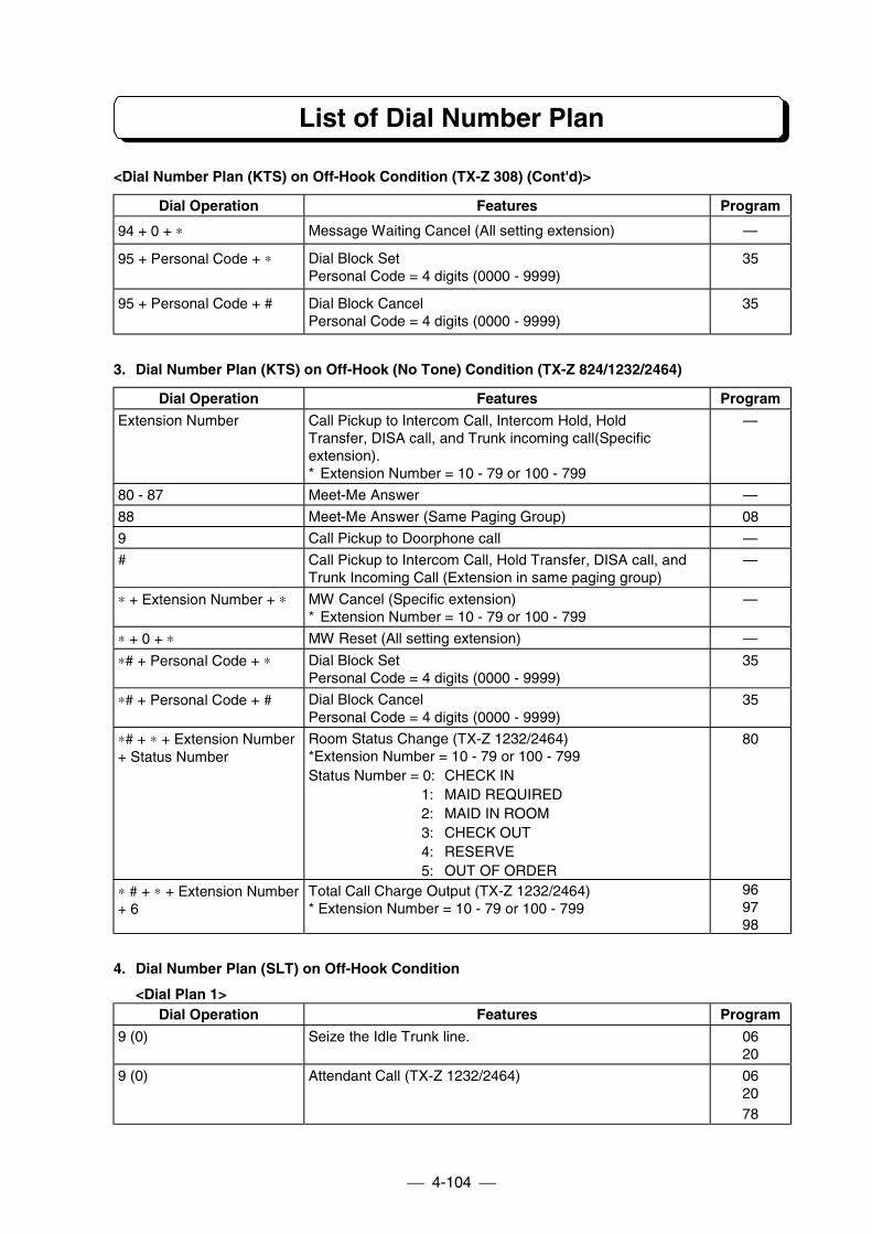
List of Dial Number Plan
4-104
<Dial Number Plan (KTS) on Off-Hook Condition (TX-Z 308) (Cont'd)>
Dial Operation Features Program
94 + 0 + ∗ Message Waiting Cancel (All setting extension) —
95 + Personal Code + ∗ Dial Block SetPersonal Code = 4 digits (0000 - 9999)
35
95 + Personal Code + # Dial Block CancelPersonal Code = 4 digits (0000 - 9999)
35
3. Dial Number Plan (KTS) on Off-Hook (No Tone) Condition (TX-Z 824/1232/2464)
Dial Operation Features Program
Extension Number Call Pickup to Intercom Call, Intercom Hold, HoldTransfer, DISA call, and Trunk incoming call(Specificextension).* Extension Number = 10 - 79 or 100 - 799
—
80 - 87 Meet-Me Answer —
88 Meet-Me Answer (Same Paging Group) 08
9 Call Pickup to Doorphone call —
# Call Pickup to Intercom Call, Hold Transfer, DISA call, andTrunk Incoming Call (Extension in same paging group)
—
∗ + Extension Number + ∗ MW Cancel (Specific extension)* Extension Number = 10 - 79 or 100 - 799
—
∗ + 0 + ∗ MW Reset (All setting extension) —
∗# + Personal Code + ∗ Dial Block SetPersonal Code = 4 digits (0000 - 9999)
35
∗# + Personal Code + # Dial Block CancelPersonal Code = 4 digits (0000 - 9999)
35
∗# + ∗ + Extension Number+ Status Number
Room Status Change (TX-Z 1232/2464)*Extension Number = 10 - 79 or 100 - 799Status Number = 0: CHECK IN
1: MAID REQUIRED2: MAID IN ROOM3: CHECK OUT4: RESERVE5: OUT OF ORDER
80
∗ # + ∗ + Extension Number+ 6
Total Call Charge Output (TX-Z 1232/2464)* Extension Number = 10 - 79 or 100 - 799
969798
4. Dial Number Plan (SLT) on Off-Hook Condition
<Dial Plan 1>Dial Operation Features Program
9 (0) Seize the Idle Trunk line. 0620
9 (0) Attendant Call (TX-Z 1232/2464) 062078
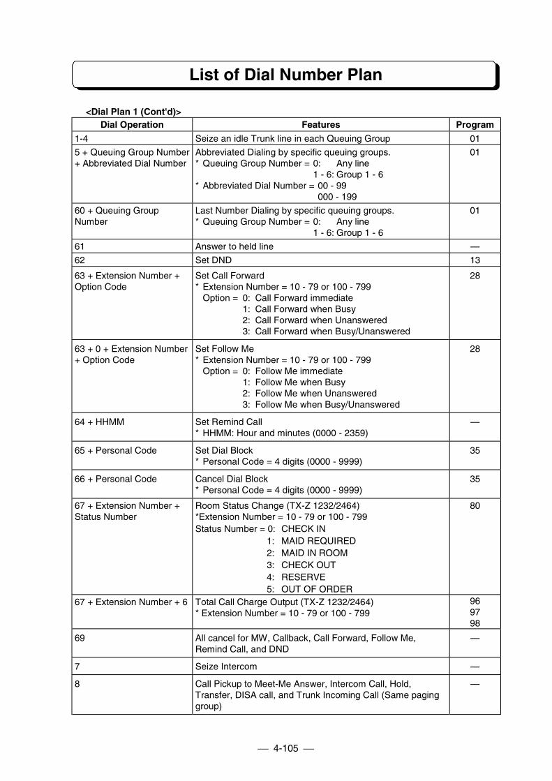
List of Dial Number Plan
4-105
<Dial Plan 1 (Cont'd)>Dial Operation Features Program
1-4 Seize an idle Trunk line in each Queuing Group 01
5 + Queuing Group Number+ Abbreviated Dial Number
Abbreviated Dialing by specific queuing groups.* Queuing Group Number = 0: Any line
1 - 6: Group 1 - 6* Abbreviated Dial Number = 00 - 99
000 - 199
01
60 + Queuing GroupNumber
Last Number Dialing by specific queuing groups.* Queuing Group Number = 0: Any line
1 - 6: Group 1 - 6
01
61 Answer to held line —
62 Set DND 13
63 + Extension Number +Option Code
Set Call Forward* Extension Number = 10 - 79 or 100 - 799
Option = 0: Call Forward immediate1: Call Forward when Busy2: Call Forward when Unanswered3: Call Forward when Busy/Unanswered
28
63 + 0 + Extension Number+ Option Code
Set Follow Me* Extension Number = 10 - 79 or 100 - 799
Option = 0: Follow Me immediate1: Follow Me when Busy2: Follow Me when Unanswered3: Follow Me when Busy/Unanswered
28
64 + HHMM Set Remind Call* HHMM: Hour and minutes (0000 - 2359)
—
65 + Personal Code Set Dial Block* Personal Code = 4 digits (0000 - 9999)
35
66 + Personal Code Cancel Dial Block* Personal Code = 4 digits (0000 - 9999)
35
67 + Extension Number +Status Number
Room Status Change (TX-Z 1232/2464)*Extension Number = 10 - 79 or 100 - 799Status Number = 0: CHECK IN
1: MAID REQUIRED2: MAID IN ROOM3: CHECK OUT4: RESERVE5: OUT OF ORDER
80
67 + Extension Number + 6 Total Call Charge Output (TX-Z 1232/2464)* Extension Number = 10 - 79 or 100 - 799
969798
69 All cancel for MW, Callback, Call Forward, Follow Me,Remind Call, and DND
—
7 Seize Intercom —
8 Call Pickup to Meet-Me Answer, Intercom Call, Hold,Transfer, DISA call, and Trunk Incoming Call (Same paginggroup)
—
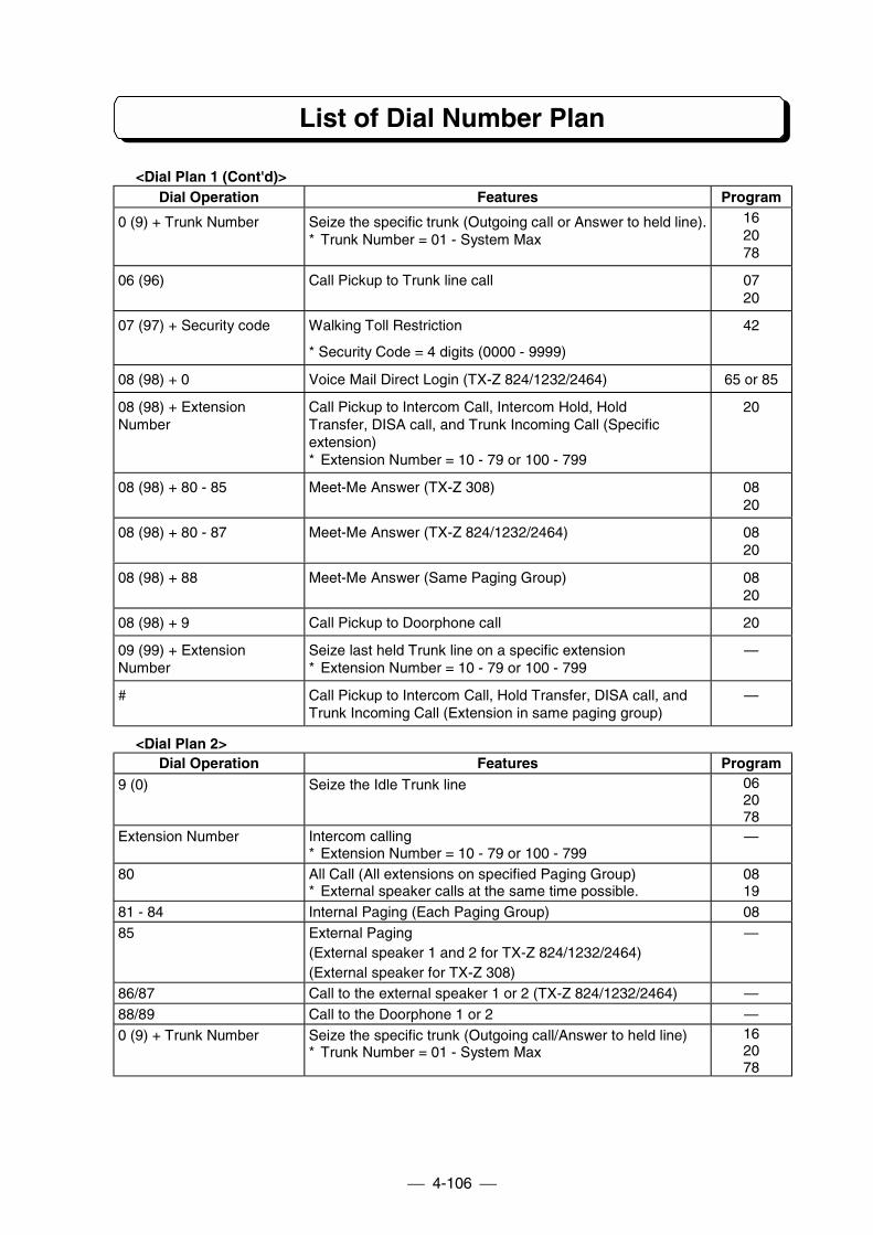
List of Dial Number Plan
4-106
<Dial Plan 1 (Cont'd)>Dial Operation Features Program
0 (9) + Trunk Number Seize the specific trunk (Outgoing call or Answer to held line).* Trunk Number = 01 - System Max
162078
06 (96) Call Pickup to Trunk line call 0720
07 (97) + Security code Walking Toll Restriction
* Security Code = 4 digits (0000 - 9999)
42
08 (98) + 0 Voice Mail Direct Login (TX-Z 824/1232/2464) 65 or 85
08 (98) + ExtensionNumber
Call Pickup to Intercom Call, Intercom Hold, HoldTransfer, DISA call, and Trunk Incoming Call (Specificextension)* Extension Number = 10 - 79 or 100 - 799
20
08 (98) + 80 - 85 Meet-Me Answer (TX-Z 308) 0820
08 (98) + 80 - 87 Meet-Me Answer (TX-Z 824/1232/2464) 0820
08 (98) + 88 Meet-Me Answer (Same Paging Group) 0820
08 (98) + 9 Call Pickup to Doorphone call 20
09 (99) + ExtensionNumber
Seize last held Trunk line on a specific extension* Extension Number = 10 - 79 or 100 - 799
—
# Call Pickup to Intercom Call, Hold Transfer, DISA call, andTrunk Incoming Call (Extension in same paging group)
—
<Dial Plan 2>Dial Operation Features Program
9 (0) Seize the Idle Trunk line 062078
Extension Number Intercom calling* Extension Number = 10 - 79 or 100 - 799
—
80 All Call (All extensions on specified Paging Group)* External speaker calls at the same time possible.
0819
81 - 84 Internal Paging (Each Paging Group) 0885 External Paging
(External speaker 1 and 2 for TX-Z 824/1232/2464)(External speaker for TX-Z 308)
—
86/87 Call to the external speaker 1 or 2 (TX-Z 824/1232/2464) —88/89 Call to the Doorphone 1 or 2 —0 (9) + Trunk Number Seize the specific trunk (Outgoing call/Answer to held line)
* Trunk Number = 01 - System Max162078
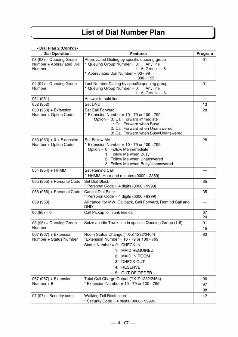
List of Dial Number Plan
4-107
<Dial Plan 2 (Cont'd)>Dial Operation Features Program
03 (93) + Queuing GroupNumber + Abbreviated DialNumber
Abbreviated Dialing by specific queuing group* Queuing Group Number = 0: Any line
1 - 6: Group 1 - 6* Abbreviated Dial Number = 00 - 99
000 - 199
01
04 (94) + Queuing GroupNumber
Last Number Dialing by specific queuing group* Queuing Group Number = 0: Any line
1 - 6: Group 1 - 6
01
051 (951) Answer to held line —052 (952) Set DND 13053 (953) + ExtensionNumber + Option Code
Set Call Forward* Extension Number = 10 - 79 or 100 - 799
Option = 0: Call Forward immediate1: Call Forward when Busy2: Call Forward when Unanswered3: Call Forward when Busy/Unanswered
28
053 (953) + 0 + ExtensionNumber + Option Code
Set Follow Me* Extension Number = 10 - 79 or 100 - 799
Option = 0: Follow Me immediate1: Follow Me when Busy2: Follow Me when Unanswered3: Follow Me when Busy/Unanswered
28
054 (954) + HHMM Set Remind Call* HHMM: Hour and minutes (0000 - 2359)
—
055 (955) + Personal Code Set Dial Block* Personal Code = 4 digits (0000 - 9999)
35
056 (956) + Personal Code Cancel Dial Block* Personal Code = 4 digits (0000 - 9999)
35
059 (959) All cancel for MW, Callback, Call Forward, Remind Call andDND
—
06 (96) + 0 Call Pickup to Trunk line call 0720
06 (96) + Queuing GroupNumber
Seize an idle Trunk line in specific Queuing Group (1-6) 0115
067 (967) + ExtensionNumber + Status Number
Room Status Change (TX-Z 1232/2464)*Extension Number = 10 - 79 or 100 - 799Status Number = 0: CHECK IN
1: MAID REQUIRED2: MAID IN ROOM3: CHECK OUT4: RESERVE5: OUT OF ORDER
80
067 (967) + ExtensionNumber + 6
Total Call Charge Output (TX-Z 1232/2464)* Extension Number = 10 - 79 or 100 - 799
969798
07 (97) + Security code Walking Toll Restriction* Security Code = 4 digits (0000 - 99999
42
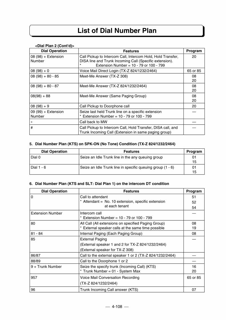
List of Dial Number Plan
4-108
<Dial Plan 2 (Cont'd)>Dial Operation Features Program
08 (98) + ExtensionNumber
Call Pickup to Intercom Call, Intercom Hold, Hold Transfer,DISA line and Trunk Incoming Call (Specific extension).* Extension Number = 10 - 79 or 100 - 799
20
08 (98) + 0 Voice Mail Direct Login (TX-Z 824/1232/2464) 65 or 8508 (98) + 80 - 85 Meet-Me Answer (TX-Z 308) 08
2008 (98) + 80 - 87 Meet-Me Answer (TX-Z 824/1232/2464) 08
20
08(98) + 88 Meet-Me Answer (Same Paging Group) 0820
08 (98) + 9 Call Pickup to Doorphone call 20
09 (99) + ExtensionNumber
Seize last held Trunk line on a specific extension* Extension Number = 10 - 79 or 100 - 799
—
∗ Call back to MW —
# Call Pickup to Intercom Call, Hold Transfer, DISA call, andTrunk Incoming Call (Extension in same paging group)
—
5. Dial Number Plan (KTS) on SPK-ON (No Tone) Condition (TX-Z 824/1232/2464)
Dial Operation Features Program
Dial 0 Seize an Idle Trunk line in the any queuing group 0115
Dial 1 - 6 Seize an Idle Trunk line in specific queuing group (1 - 6) 0115
6. Dial Number Plan (KTS and SLT: Dial Plan 1) on the intercom DT condition
Dial Operation Features Program
0 Call to attendant* Attendant = No. 10 extension, specific extension
at each tenant
515254
Extension Number Intercom call* Extension Number = 10 - 79 or 100 - 799
—
80 All Call (All extensions on specified Paging Group)* External speaker calls at the same time possible
0819
81 - 84 Internal Paging (Each Paging Group) 08
85 External Paging(External speaker 1 and 2 for TX-Z 824/1232/2464)(External speaker for TX-Z 308)
—
86/87 Call to the external speaker 1 or 2 (TX-Z 824/1232/2464) —
88/89 Call to the Doorphone 1 or 2 —
9 + Trunk Number Seize the specify trunk (Incoming Call) (KTS)* Trunk Number = 01 - System Max
1620
957 Voice Mail Conversation Recording
(TX-Z 824/1232/2464)
65 or 85
96 Trunk Incoming Call answer (KTS) 07
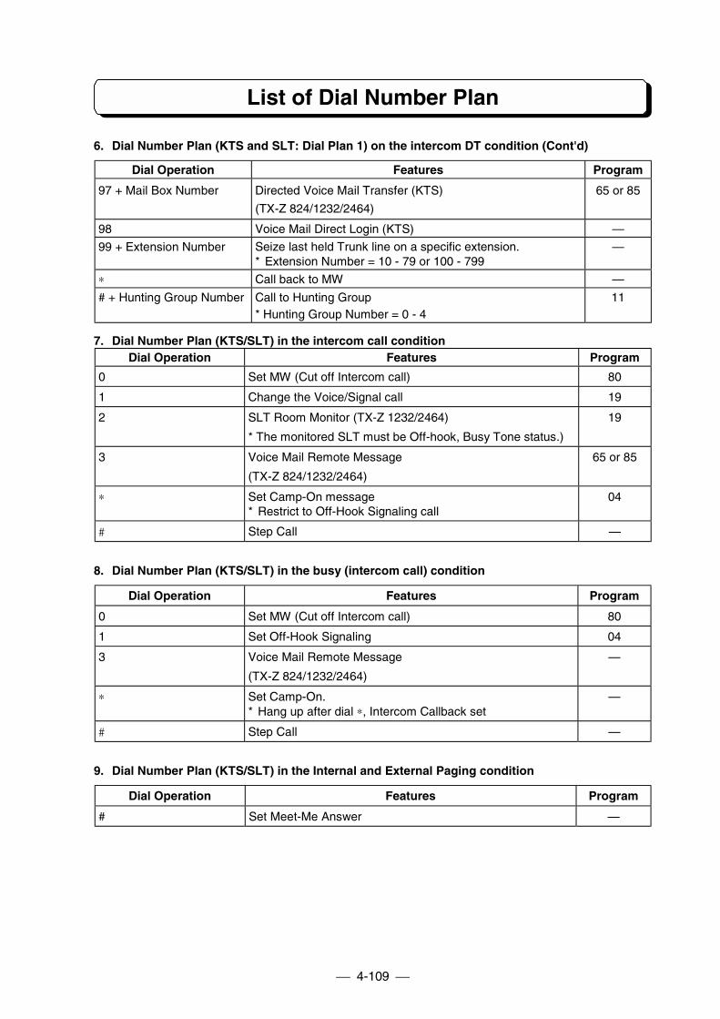
List of Dial Number Plan
4-109
6. Dial Number Plan (KTS and SLT: Dial Plan 1) on the intercom DT condition (Cont'd)
Dial Operation Features Program
97 + Mail Box Number Directed Voice Mail Transfer (KTS)
(TX-Z 824/1232/2464)
65 or 85
98 Voice Mail Direct Login (KTS) —
99 + Extension Number Seize last held Trunk line on a specific extension.* Extension Number = 10 - 79 or 100 - 799
—
∗ Call back to MW —
# + Hunting Group Number Call to Hunting Group* Hunting Group Number = 0 - 4
11
7. Dial Number Plan (KTS/SLT) in the intercom call conditionDial Operation Features Program
0 Set MW (Cut off Intercom call) 80
1 Change the Voice/Signal call 19
2 SLT Room Monitor (TX-Z 1232/2464)
* The monitored SLT must be Off-hook, Busy Tone status.)
19
3 Voice Mail Remote Message
(TX-Z 824/1232/2464)
65 or 85
∗ Set Camp-On message* Restrict to Off-Hook Signaling call
04
# Step Call —
8. Dial Number Plan (KTS/SLT) in the busy (intercom call) condition
Dial Operation Features Program
0 Set MW (Cut off Intercom call) 80
1 Set Off-Hook Signaling 04
3 Voice Mail Remote Message
(TX-Z 824/1232/2464)
—
∗ Set Camp-On.* Hang up after dial ∗, Intercom Callback set
—
# Step Call —
9. Dial Number Plan (KTS/SLT) in the Internal and External Paging condition
Dial Operation Features Program
# Set Meet-Me Answer —
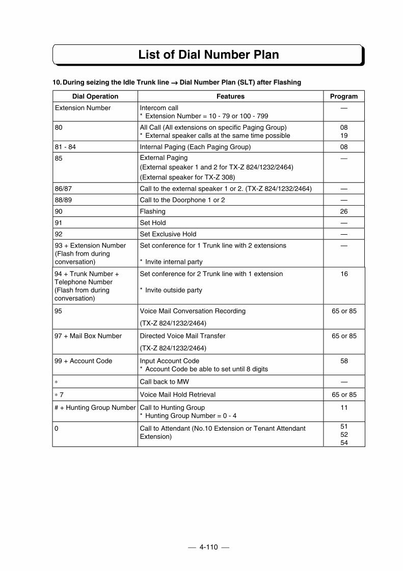
List of Dial Number Plan
4-110
10.During seizing the Idle Trunk line →→→→ Dial Number Plan (SLT) after Flashing
Dial Operation Features Program
Extension Number Intercom call* Extension Number = 10 - 79 or 100 - 799
—
80 All Call (All extensions on specific Paging Group)* External speaker calls at the same time possible
0819
81 - 84 Internal Paging (Each Paging Group) 08
85 External Paging(External speaker 1 and 2 for TX-Z 824/1232/2464)
(External speaker for TX-Z 308)
—
86/87 Call to the external speaker 1 or 2. (TX-Z 824/1232/2464) —
88/89 Call to the Doorphone 1 or 2 —
90 Flashing 26
91 Set Hold —
92 Set Exclusive Hold —
93 + Extension Number(Flash from duringconversation)
Set conference for 1 Trunk line with 2 extensions
* Invite internal party
—
94 + Trunk Number +Telephone Number(Flash from duringconversation)
Set conference for 2 Trunk line with 1 extension
* Invite outside party
16
95 Voice Mail Conversation Recording
(TX-Z 824/1232/2464)
65 or 85
97 + Mail Box Number Directed Voice Mail Transfer
(TX-Z 824/1232/2464)
65 or 85
99 + Account Code Input Account Code* Account Code be able to set until 8 digits
58
∗ Call back to MW —
∗ 7 Voice Mail Hold Retrieval 65 or 85
# + Hunting Group Number Call to Hunting Group* Hunting Group Number = 0 - 4
11
0 Call to Attendant (No.10 Extension or Tenant AttendantExtension)
515254
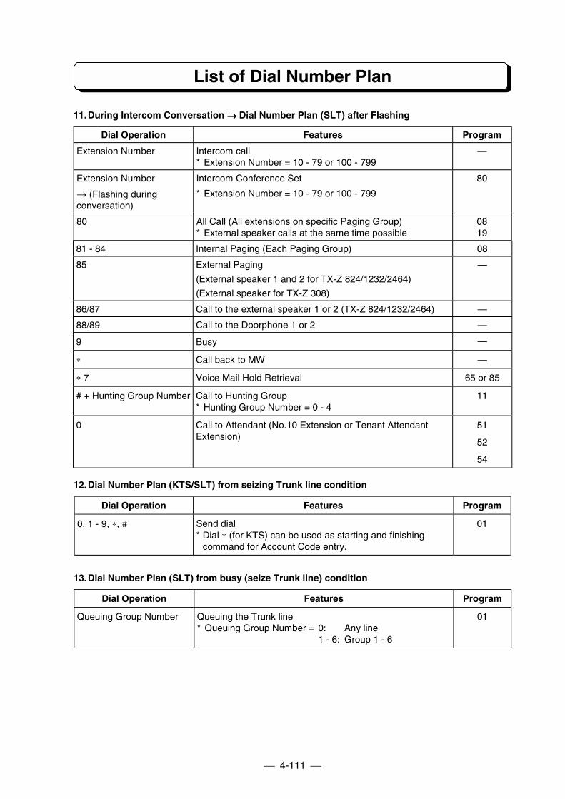
List of Dial Number Plan
4-111
11.During Intercom Conversation →→→→ Dial Number Plan (SLT) after Flashing
Dial Operation Features Program
Extension Number Intercom call* Extension Number = 10 - 79 or 100 - 799
—
Extension Number
→ (Flashing duringconversation)
Intercom Conference Set
* Extension Number = 10 - 79 or 100 - 799
80
80 All Call (All extensions on specific Paging Group)* External speaker calls at the same time possible
0819
81 - 84 Internal Paging (Each Paging Group) 08
85 External Paging
(External speaker 1 and 2 for TX-Z 824/1232/2464)
(External speaker for TX-Z 308)
—
86/87 Call to the external speaker 1 or 2 (TX-Z 824/1232/2464) —
88/89 Call to the Doorphone 1 or 2 —
9 Busy —
∗ Call back to MW —
∗ 7 Voice Mail Hold Retrieval 65 or 85
# + Hunting Group Number Call to Hunting Group* Hunting Group Number = 0 - 4
11
0 Call to Attendant (No.10 Extension or Tenant AttendantExtension)
51
52
54
12.Dial Number Plan (KTS/SLT) from seizing Trunk line condition
Dial Operation Features Program
0, 1 - 9, ∗, # Send dial* Dial ∗ (for KTS) can be used as starting and finishing
command for Account Code entry.
01
13.Dial Number Plan (SLT) from busy (seize Trunk line) condition
Dial Operation Features Program
Queuing Group Number Queuing the Trunk line* Queuing Group Number = 0: Any line
1 - 6: Group 1 - 6
01
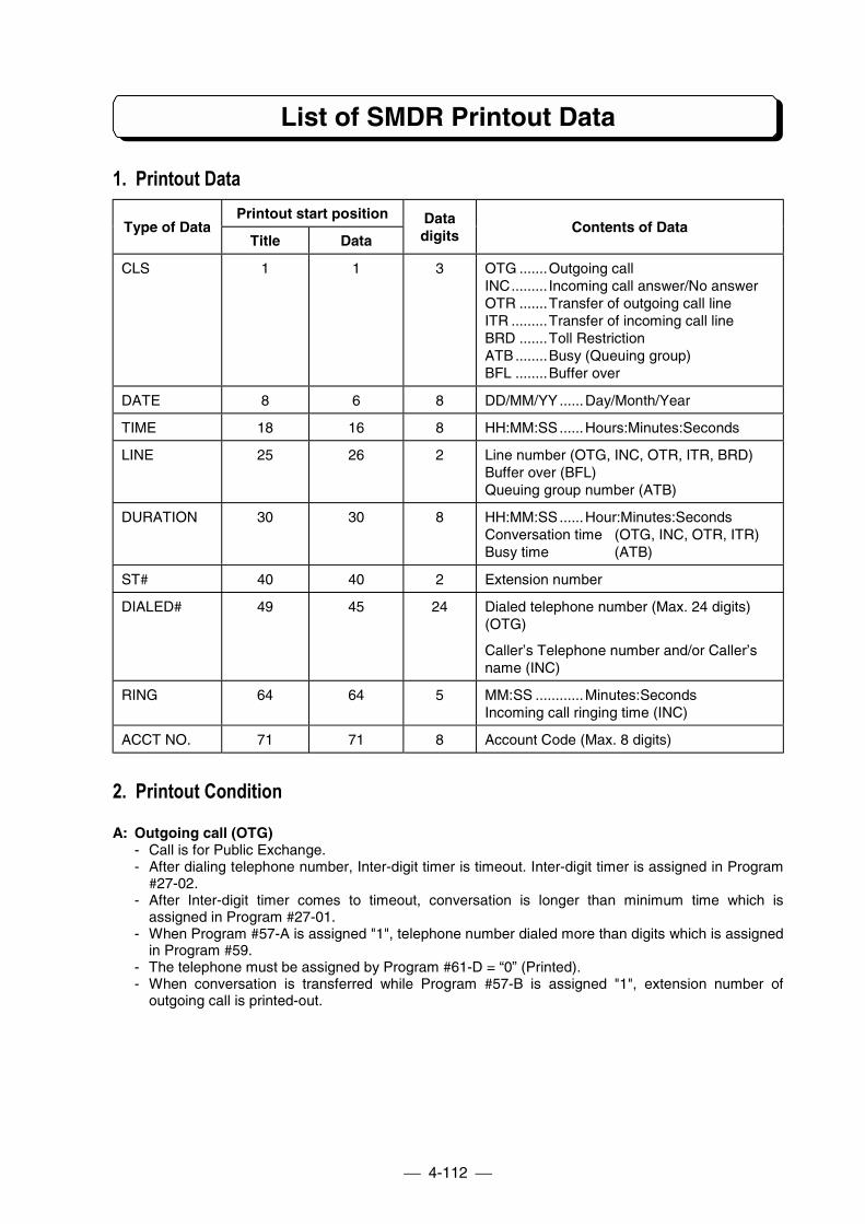
List of SMDR Printout Data
4-112
1. Printout DataPrintout start position
Type of DataTitle Data
Datadigits
Contents of Data
CLS 1 1 3 OTG .......Outgoing callINC......... Incoming call answer/No answerOTR .......Transfer of outgoing call lineITR .........Transfer of incoming call lineBRD .......Toll RestrictionATB ........Busy (Queuing group)BFL ........Buffer over
DATE 8 6 8 DD/MM/YY......Day/Month/Year
TIME 18 16 8 HH:MM:SS......Hours:Minutes:Seconds
LINE 25 26 2 Line number (OTG, INC, OTR, ITR, BRD)Buffer over (BFL)Queuing group number (ATB)
DURATION 30 30 8 HH:MM:SS......Hour:Minutes:SecondsConversation time (OTG, INC, OTR, ITR)Busy time (ATB)
ST# 40 40 2 Extension number
DIALED# 49 45 24 Dialed telephone number (Max. 24 digits)(OTG)
Caller’s Telephone number and/or Caller’sname (INC)
RING 64 64 5 MM:SS ............Minutes:SecondsIncoming call ringing time (INC)
ACCT NO. 71 71 8 Account Code (Max. 8 digits)
2. Printout Condition
A: Outgoing call (OTG)- Call is for Public Exchange.- After dialing telephone number, Inter-digit timer is timeout. Inter-digit timer is assigned in Program
#27-02.- After Inter-digit timer comes to timeout, conversation is longer than minimum time which is
assigned in Program #27-01.- When Program #57-A is assigned "1", telephone number dialed more than digits which is assigned
in Program #59.- The telephone must be assigned by Program #61-D = “0” (Printed).- When conversation is transferred while Program #57-B is assigned "1", extension number of
outgoing call is printed-out.
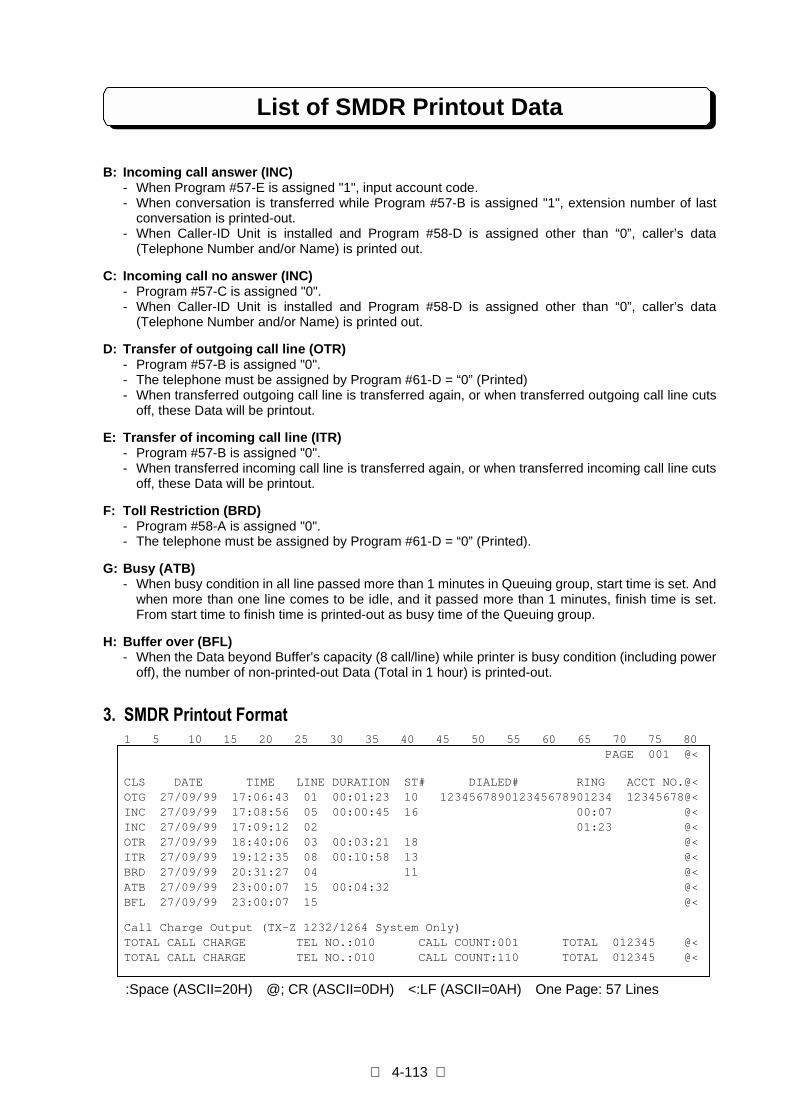
List of SMDR Printout Data
4-113
B: Incoming call answer (INC)- When Program #57-E is assigned "1", input account code.- When conversation is transferred while Program #57-B is assigned "1", extension number of last
conversation is printed-out.- When Caller-ID Unit is installed and Program #58-D is assigned other than “0”, caller’s data
(Telephone Number and/or Name) is printed out.
C: Incoming call no answer (INC)- Program #57-C is assigned "0".- When Caller-ID Unit is installed and Program #58-D is assigned other than “0”, caller’s data
(Telephone Number and/or Name) is printed out.
D: Transfer of outgoing call line (OTR)- Program #57-B is assigned "0".- The telephone must be assigned by Program #61-D = “0” (Printed)- When transferred outgoing call line is transferred again, or when transferred outgoing call line cuts
off, these Data will be printout.
E: Transfer of incoming call line (ITR)- Program #57-B is assigned "0".- When transferred incoming call line is transferred again, or when transferred incoming call line cuts
off, these Data will be printout.
F: Toll Restriction (BRD)- Program #58-A is assigned "0".- The telephone must be assigned by Program #61-D = “0” (Printed).
G: Busy (ATB)- When busy condition in all line passed more than 1 minutes in Queuing group, start time is set. And
when more than one line comes to be idle, and it passed more than 1 minutes, finish time is set.From start time to finish time is printed-out as busy time of the Queuing group.
H: Buffer over (BFL)- When the Data beyond Buffer's capacity (8 call/line) while printer is busy condition (including power
off), the number of non-printed-out Data (Total in 1 hour) is printed-out.
3. SMDR Printout Format1 5 10 15 20 25 30 35 40 45 50 55 60 65 70 75 80
PAGE 001 @<
CLS DATE TIME LINE DURATION ST# DIALED# RING ACCT NO.@<OTG 27/09/99 17:06:43 01 00:01:23 10 123456789012345678901234 12345678@<INC 27/09/99 17:08:56 05 00:00:45 16 00:07 @<INC 27/09/99 17:09:12 02 01:23 @<OTR 27/09/99 18:40:06 03 00:03:21 18 @<ITR 27/09/99 19:12:35 08 00:10:58 13 @<BRD 27/09/99 20:31:27 04 11 @<ATB 27/09/99 23:00:07 15 00:04:32 @<BFL 27/09/99 23:00:07 15 @<
Call Charge Output (TX-Z 1232/1264 System Only)TOTAL CALL CHARGE TEL NO.:010 CALL COUNT:001 TOTAL 012345 @<TOTAL CALL CHARGE TEL NO.:010 CALL COUNT:110 TOTAL 012345 @<
:Space (ASCII=20H) @; CR (ASCII=0DH) <:LF (ASCII=0AH) One Page: 57 Lines
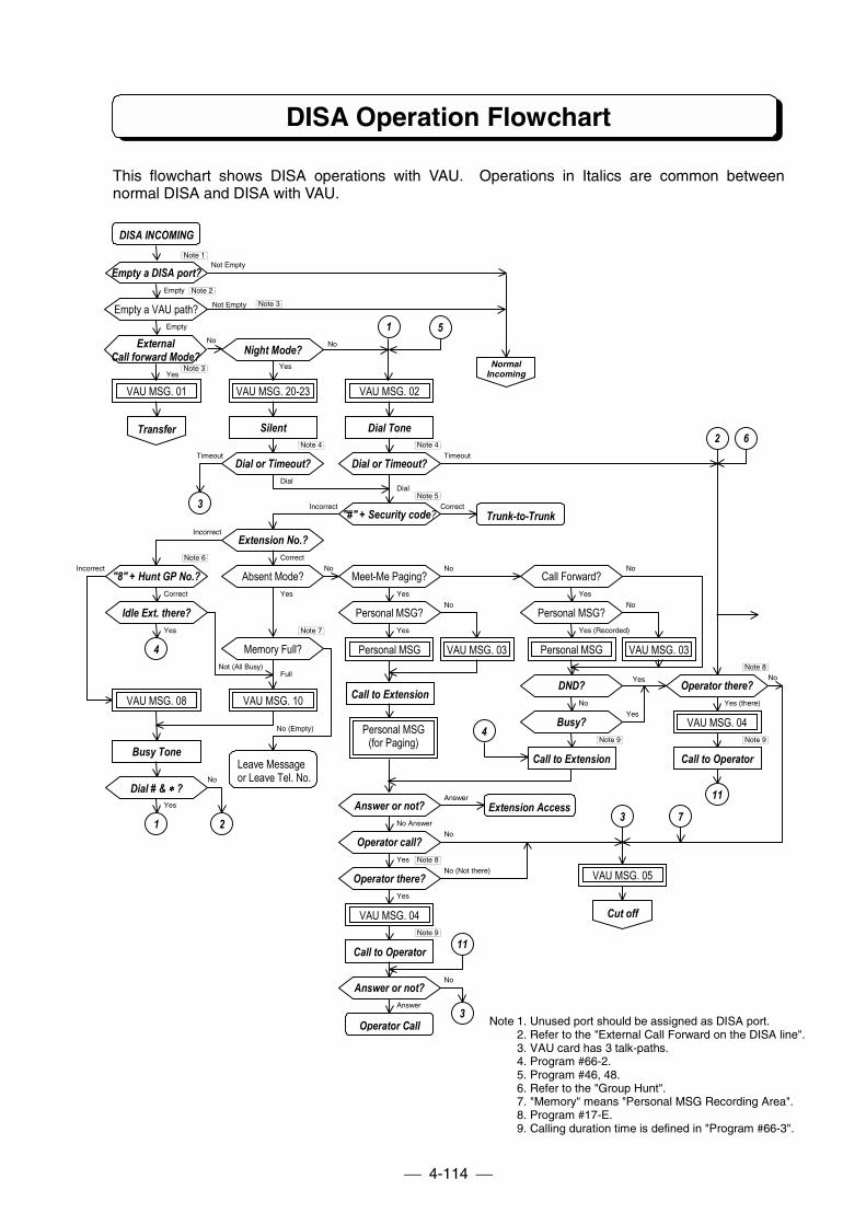
DISA Operation Flowchart
4-114
This flowchart shows DISA operations with VAU. Operations in Italics are common betweennormal DISA and DISA with VAU.
Busy Tone
Operator Call
Leave Messageor Leave Tel. No.
Extension Access
Trunk-to-Trunk
DISA INCOMING
Empty a DISA port?
ExternalCall forward Mode?
Empty a VAU path?
VAU MSG. 01
Silent
VAU MSG. 20-23
Dial or Timeout?
Note 3
Dial
No
No No
Incorrect Correct
Timeout
Yes
Yes
Dial
Yes
Incorrect
Timeout
Yes
Not (All Busy)
Correct
Yes
Full
No (Empty)
No
Incorrect
Yes
Correct
Empty
No No
Not Empty
Yes
Not Empty
Empty
Note 6
Note 7
Note 9
Note 8
Note 9
Note 8
Note 5
Note 4Note 4
Note 3
Note 2
Note 1
Note 1. Unused port should be assigned as DISA port.2. Refer to the "External Call Forward on the DISA line".3. VAU card has 3 talk-paths.4. Program #66-2.5. Program #46, 48.6. Refer to the "Group Hunt".7. "Memory" means "Personal MSG Recording Area".8. Program #17-E.9. Calling duration time is defined in "Program #66-3".
Call to Operator
Dial or Timeout?
Call to Extension
Dial Tone
"#" + Security code?
VAU MSG. 02
Extension No.?
Absent Mode?"8" + Hunt GP No.?
Idle Ext. there?
Meet-Me Paging?
Personal MSG?
VAU MSG. 10
Memory Full?
VAU MSG. 08
Dial # & ∗∗∗∗ ?
Personal MSG
Personal MSG(for Paging)
VAU MSG. 03
Operator call?
Operator there?
Answer or not?
VAU MSG. 04
Answer or not?
Night Mode?
Call Forward?
Personal MSG?
Personal MSG VAU MSG. 03
DND?
Busy?
VAU MSG. 05
Call to Operator
Operator there?
Transfer
VAU MSG. 04
NormalIncoming
Cut off
1
No
No
Yes (there)
Answer
No Answer
No
Yes
No
No (Not there)
Answer
Yes
No
No
Yes
Yes (Recorded)
Yes
Note 9
5
3
4
4
1 2 3 7
11
2 6
11
3
Yes
Call to Extension
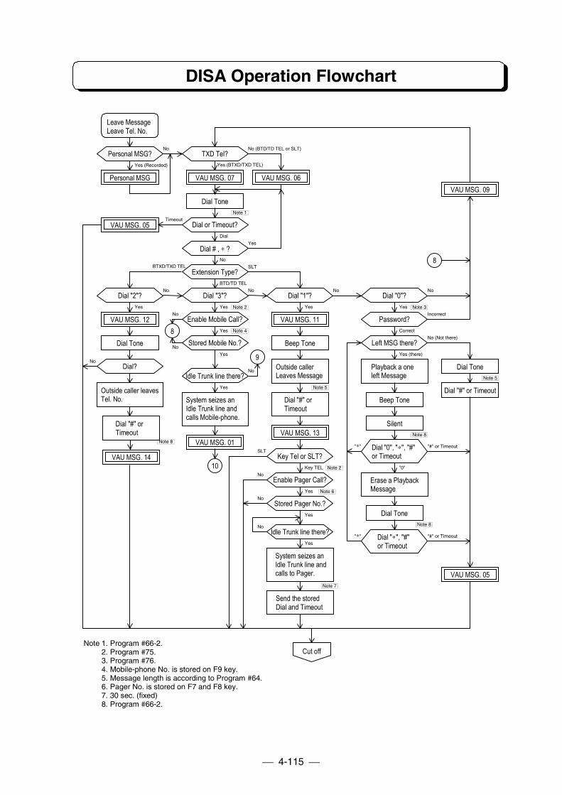
DISA Operation Flowchart
4-115
Dial Tone
Dial Tone
Dial "#" orTimeout
Playback a oneleft Message
Outside callerLeaves Message
Outside caller leavesTel. No.
Leave MessageLeave Tel. No.
Personal MSG?
Personal MSG
TXD Tel?
VAU MSG. 07 VAU MSG. 06
VAU MSG. 05 Dial or Timeout?
Dial # , ∗ ?
Extension Type?
Dial "3"?
Enable Mobile Call?
Stored Mobile No.?
Dial "2"?
VAU MSG. 12
Dial?Idle Trunk line there?
VAU MSG. 14
System seizes anIdle Trunk line andcalls Mobile-phone.
VAU MSG. 01
Dial "#" or Timeout
Dial Tone
Silent
Beep Tone
Beep Tone
Dial "1"?
VAU MSG. 11
VAU MSG. 13
Key Tel or SLT?
Enable Pager Call?
Stored Pager No.?
Idle Trunk line there?
Send the storedDial and Timeout
System seizes anIdle Trunk line andcalls to Pager.
Dial "0"?
Password?
Left MSG there?
Dial "0", "∗", "#"or Timeout
Erase a PlaybackMessage
Dial Tone
Dial "∗", "#"or Timeout
VAU MSG. 05
VAU MSG. 09
Cut off
Note 7
Note 6
Note 2
Note 5
Note 4
Note 8
Note 8
Note 5
Note 3Note 2
Note 1
BTXD/TXD TEL
Timeout
Yes (BTXD/TXD TEL)Yes (Recorded)
Dial
Yes
Yes
No (BTD/TD TEL or SLT)No
8
8
9
10
No
SLT
No
No
No
No
No
No
No
Yes
Yes
Yes
Key TEL
SLT
Yes
Yes
Yes
BTD/TD TEL
No
Yes
NoNo
Yes
Incorrect
"∗" "#" or Timeout
Yes (there)
"0"
Correct
No (Not there)
"∗" "#" or Timeout
Yes
No
Note 1. Program #66-2.2. Program #75.3. Program #76.4. Mobile-phone No. is stored on F9 key.5. Message length is according to Program #64.6. Pager No. is stored on F7 and F8 key.7. 30 sec. (fixed)8. Program #66-2.
Dial "#" orTimeout
Note 8
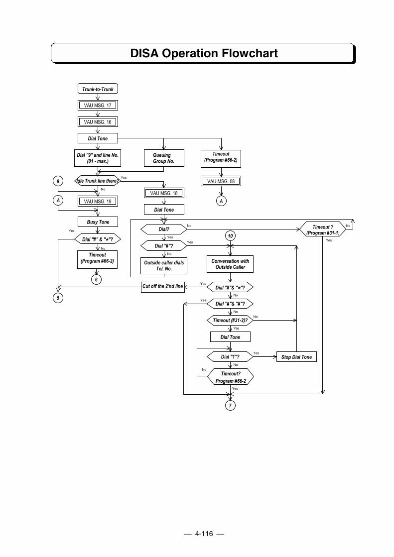
DISA Operation Flowchart
4-116
Idle Trunk line there?
QueuingGroup No.
Dial "9" and line No.(01 - max.)
Dial Tone
VAU MSG. 17
Trunk-to-Trunk
Yes
No
No
No
No
No
No
No
No
No
No
Yes
Yes
Yes
Yes
Yes
YesYes
Yes
Yes
10
VAU MSG. 16
Busy Tone
VAU MSG. 19
Cut off the 2'nd line
Dial Tone
Stop Dial Tone
Conversation withOutside Caller
Outside caller dialsTel. No.
Dial Tone
VAU MSG. 18
Dial?
Dial "#"?
Dial "#"& "∗∗∗∗"?
Dial "#"& "#"?
Timeout (#31-2)?
Dial "1"?
Timeout?Program #66-2
Timeout ?(Program #31-1)
Dial "#" & "∗∗∗∗"?
9
6
5
7
A
Timeout(Program #66-2)
VAU MSG. 08
A
Timeout(Program #66-2)

PART 5
SYSTEM PROGRAMMING
Table of Contents
Location of Controls...........................................................................................5-1
System Programming Procedure....................................................................5-2
Feature Programming ........................................................................................5-4
Program 1 Line Assignment 1........................................................................5-5A. Line TypeB. Dial ModeC. Queuing GroupD. PBX Night ModeE. Polarity Reverse Detect
Program 2 Line Group Assignment................................................................5-5
Program 3 Line Assignment 2........................................................................5-6A. Direct Inward System Access (DISA) lineB. DISA Line AccessC. Common Use Line AssignmentD. Unrestricted LinesE. Caller-ID Line
Program 4 Extension Assignment 1...............................................................5-7A. Break-InB. Trunk Off-Hook SignalingC. Intercom Off-Hook SignalingD. Intercom Signal CallE. Headset operation
Program 5 Unsupervised Conference Port Assignment................................5-7
Program 6 Outgoing Trunk Access................................................................5-8
Program 7 Incoming Trunk Access/Audible...................................................5-8
Program 8 Extension Assignment 2...............................................................5-9A. Instrument TypeB. SLT Dial Plan SetC. Internal Page ZoneD. Tenant GroupE. Park Hold Group
Program 9 Forwarding Pairs Assignment ......................................................5-9
Program 10 Dual Handsfree Hotline ..............................................................5-10
Program 11 Hunting Groups ..........................................................................5-10
Program 12 Doorphone Call ..........................................................................5-11
Program 13 Extension Assignment 3.............................................................5-11A. Key Touch ToneB. Do Not DisturbC. Alarm AudibleD. Voice Announce Device PortE. Terminal Connection (Only for SLT)
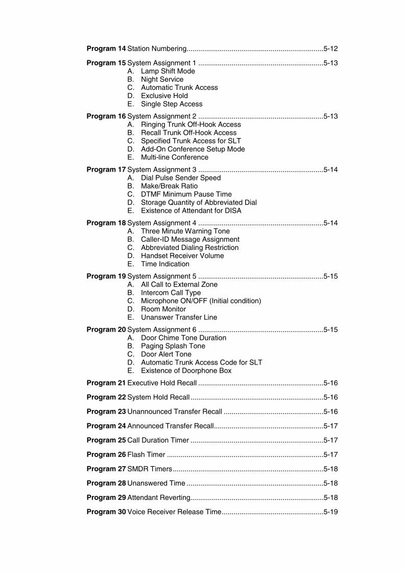
Program 14 Station Numbering......................................................................5-12
Program 15 System Assignment 1 ................................................................5-13A. Lamp Shift ModeB. Night ServiceC. Automatic Trunk AccessD. Exclusive HoldE. Single Step Access
Program 16 System Assignment 2 ................................................................5-13A. Ringing Trunk Off-Hook AccessB. Recall Trunk Off-Hook AccessC. Specified Trunk Access for SLTD. Add-On Conference Setup ModeE. Multi-line Conference
Program 17 System Assignment 3 ................................................................5-14A. Dial Pulse Sender SpeedB. Make/Break RatioC. DTMF Minimum Pause TimeD. Storage Quantity of Abbreviated DialE. Existence of Attendant for DISA
Program 18 System Assignment 4 ................................................................5-14A. Three Minute Warning ToneB. Caller-ID Message AssignmentC. Abbreviated Dialing RestrictionD. Handset Receiver VolumeE. Time Indication
Program 19 System Assignment 5 ................................................................5-15A. All Call to External ZoneB. Intercom Call TypeC. Microphone ON/OFF (Initial condition)D. Room MonitorE. Unanswer Transfer Line
Program 20 System Assignment 6 ................................................................5-15A. Door Chime Tone DurationB. Paging Splash ToneC. Door Alert ToneD. Automatic Trunk Access Code for SLTE. Existence of Doorphone Box
Program 21 Executive Hold Recall ................................................................5-16
Program 22 System Hold Recall ....................................................................5-16
Program 23 Unannounced Transfer Recall ...................................................5-16
Program 24 Announced Transfer Recall........................................................5-17
Program 25 Call Duration Timer ....................................................................5-17
Program 26 Flash Timer ................................................................................5-17
Program 27 SMDR Timers.............................................................................5-18
Program 28 Unanswered Time ......................................................................5-18
Program 29 Attendant Reverting....................................................................5-18
Program 30 Voice Receiver Release Time....................................................5-19
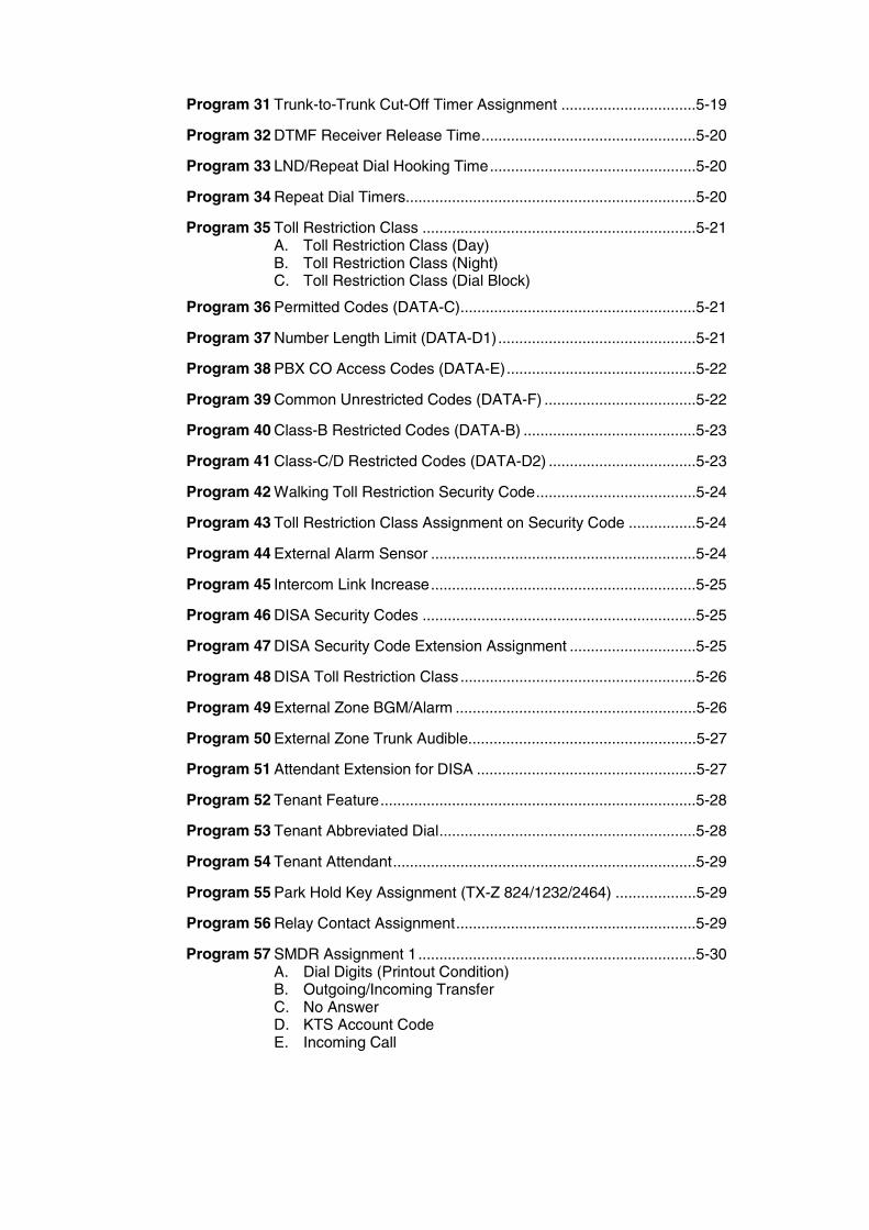
Program 31 Trunk-to-Trunk Cut-Off Timer Assignment ................................5-19
Program 32 DTMF Receiver Release Time...................................................5-20
Program 33 LND/Repeat Dial Hooking Time.................................................5-20
Program 34 Repeat Dial Timers.....................................................................5-20
Program 35 Toll Restriction Class .................................................................5-21A. Toll Restriction Class (Day)B. Toll Restriction Class (Night)C. Toll Restriction Class (Dial Block)
Program 36 Permitted Codes (DATA-C)........................................................5-21
Program 37 Number Length Limit (DATA-D1)...............................................5-21
Program 38 PBX CO Access Codes (DATA-E).............................................5-22
Program 39 Common Unrestricted Codes (DATA-F) ....................................5-22
Program 40 Class-B Restricted Codes (DATA-B) .........................................5-23
Program 41 Class-C/D Restricted Codes (DATA-D2) ...................................5-23
Program 42 Walking Toll Restriction Security Code......................................5-24
Program 43 Toll Restriction Class Assignment on Security Code ................5-24
Program 44 External Alarm Sensor ...............................................................5-24
Program 45 Intercom Link Increase...............................................................5-25
Program 46 DISA Security Codes .................................................................5-25
Program 47 DISA Security Code Extension Assignment ..............................5-25
Program 48 DISA Toll Restriction Class........................................................5-26
Program 49 External Zone BGM/Alarm .........................................................5-26
Program 50 External Zone Trunk Audible......................................................5-27
Program 51 Attendant Extension for DISA ....................................................5-27
Program 52 Tenant Feature...........................................................................5-28
Program 53 Tenant Abbreviated Dial.............................................................5-28
Program 54 Tenant Attendant........................................................................5-29
Program 55 Park Hold Key Assignment (TX-Z 824/1232/2464) ...................5-29
Program 56 Relay Contact Assignment.........................................................5-29
Program 57 SMDR Assignment 1..................................................................5-30A. Dial Digits (Printout Condition)B. Outgoing/Incoming TransferC. No AnswerD. KTS Account CodeE. Incoming Call
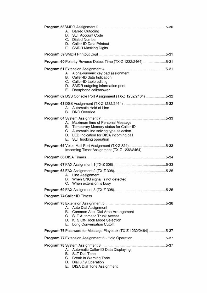
Program 58SMDR Assignment 2...................................................................5-30A. Barred OutgoingB. SLT Account CodeC. Dialed NumberD. Caller-ID Data PrintoutE. SMDR Masking Digits
Program 59 SMDR Printout Digit ...................................................................5-31
Program 60 Polarity Reverse Detect Time (TX-Z 1232/2464).......................5-31
Program 61 Extension Assignment 4.............................................................5-31A. Alpha-numeric key pad assignmentB. Caller-ID data IndicationC. Caller-ID table editingD. SMDR outgoing information printE. Doorphone call/answer
Program 62 DSS Console Port Assignment (TX-Z 1232/2464) ....................5-32
Program 63 DSS Assignment (TX-Z 1232/2464) ..........................................5-32A. Automatic Hold of LineB. DND Override
Program 64 System Assignment 7 ................................................................5-33A. Maximum time of Personal MessageB. Temporary Memory status for Caller-IDC. Automatic line seizing type selectionD. LED Indication for DISA incoming callE. SLT hooking operation
Program 65 Voice Mail Port Assignment (TX-Z 824).....................................5-33Imcoming Timer Assignment (TX-Z 1232/2464)
Program 66 DISA Timers ...............................................................................5-34
Program 67 FAX Assignment 1(TX-Z 308)....................................................5-33
Program 68 FAX Assignment 2 (TX-Z 308). ..................................................5-35A. Line AssignmentB. When CNG signal is not detectedC. When extension is busy
Program 69 FAX Assignment 3 (TX-Z 308). ..................................................5-35
Program 74 Caller-ID Timers
Program 75 Extension Assignment 5 ............................................................5-36A. Auto Dial AssignmentB. Common Abb. Dial Area ArrangementC. SLT Automatic Trunk AccessD. KTS Off-Hook Mode SelectionE. Long Conversation Cutoff
Program 76 Password for Message Playback (TX-Z 1232/2464) .................5-37
Program 77 Extension Assignment 6 - Hold Operation.................................5-37
Program 78 System Assignment 8 ................................................................5-37A. Automatic Caller-ID Data DisplayingB. SLT Dial ToneC. Break In Warning ToneD. Dial 0 / 9 OperationE. DISA Dial Tone Assignment
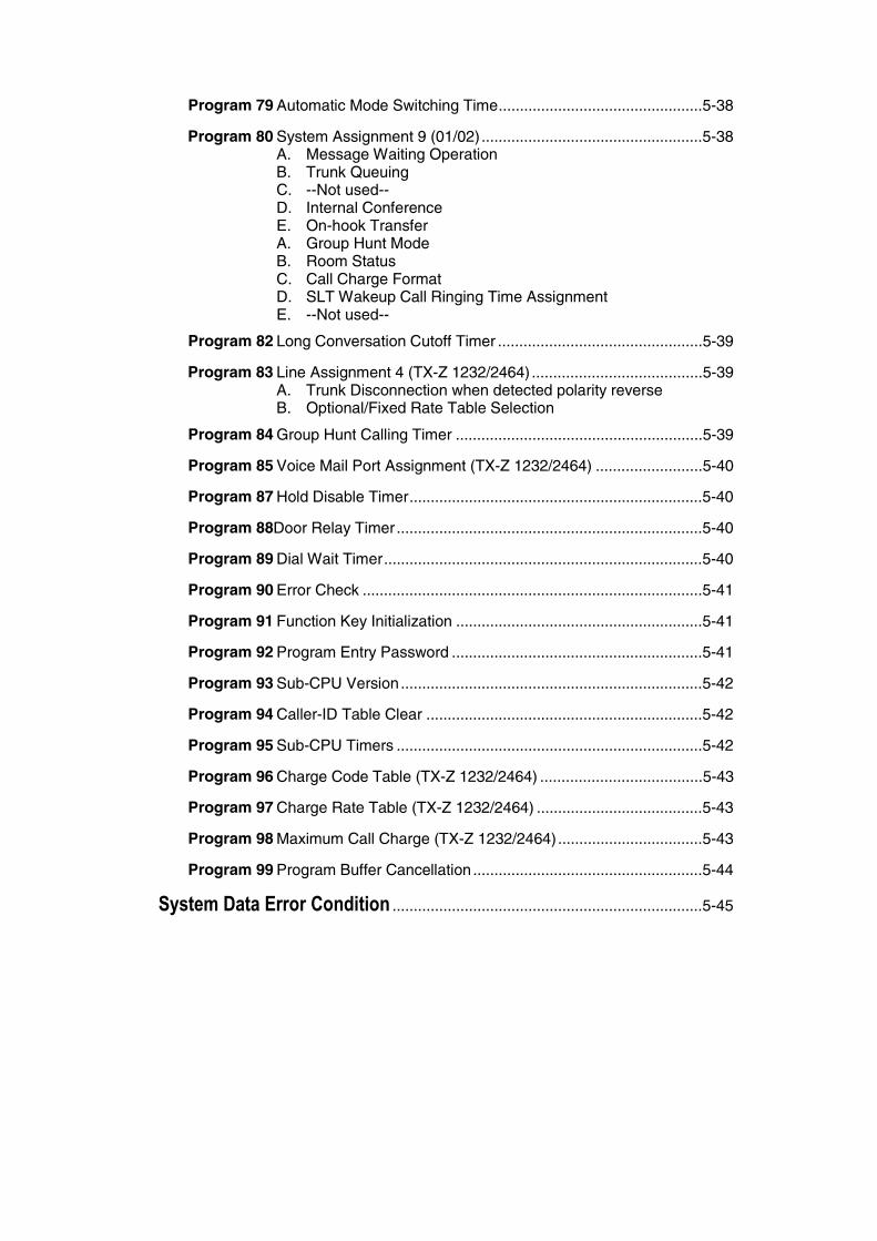
Program 79 Automatic Mode Switching Time................................................5-38
Program 80 System Assignment 9 (01/02)....................................................5-38A. Message Waiting OperationB. Trunk QueuingC. --Not used--D. Internal ConferenceE. On-hook TransferA. Group Hunt ModeB. Room StatusC. Call Charge FormatD. SLT Wakeup Call Ringing Time AssignmentE. --Not used--
Program 82 Long Conversation Cutoff Timer ................................................5-39
Program 83 Line Assignment 4 (TX-Z 1232/2464) ........................................5-39A. Trunk Disconnection when detected polarity reverseB. Optional/Fixed Rate Table Selection
Program 84 Group Hunt Calling Timer ..........................................................5-39
Program 85 Voice Mail Port Assignment (TX-Z 1232/2464) .........................5-40
Program 87 Hold Disable Timer.....................................................................5-40
Program 88Door Relay Timer ........................................................................5-40
Program 89 Dial Wait Timer...........................................................................5-40
Program 90 Error Check ................................................................................5-41
Program 91 Function Key Initialization ..........................................................5-41
Program 92 Program Entry Password ...........................................................5-41
Program 93 Sub-CPU Version.......................................................................5-42
Program 94 Caller-ID Table Clear .................................................................5-42
Program 95 Sub-CPU Timers ........................................................................5-42
Program 96 Charge Code Table (TX-Z 1232/2464) ......................................5-43
Program 97 Charge Rate Table (TX-Z 1232/2464) .......................................5-43
Program 98 Maximum Call Charge (TX-Z 1232/2464)..................................5-43
Program 99 Program Buffer Cancellation......................................................5-44
System Data Error Condition .........................................................................5-45
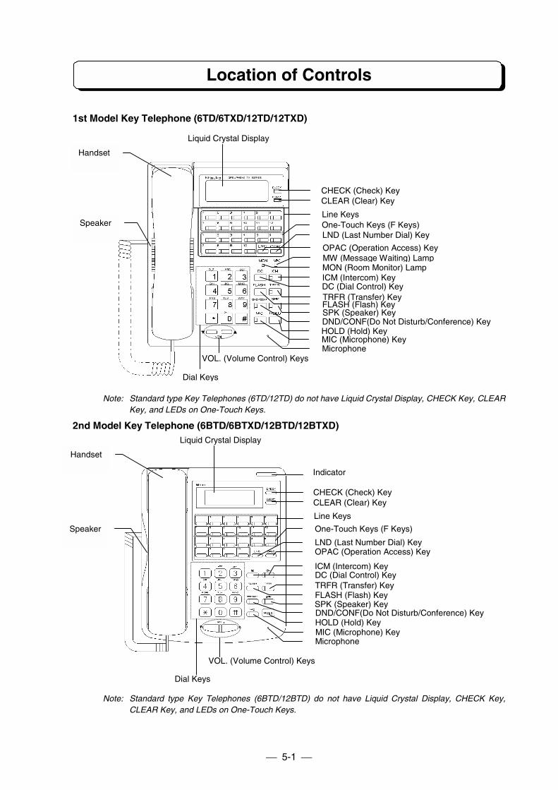
5-1
Location of Controls
1st Model Key Telephone (6TD/6TXD/12TD/12TXD)
Note: Standard type Key Telephones (6TD/12TD) do not have Liquid Crystal Display, CHECK Key, CLEARKey, and LEDs on One-Touch Keys.
2nd Model Key Telephone (6BTD/6BTXD/12BTD/12BTXD)
Note: Standard type Key Telephones (6BTD/12BTD) do not have Liquid Crystal Display, CHECK Key,CLEAR Key, and LEDs on One-Touch Keys.
CHECK (Check) KeyCLEAR (Clear) Key
Line Keys
Liquid Crystal Display
VOL. (Volume Control) Keys
Dial Keys
One-Touch Keys (F Keys)LND (Last Number Dial) Key
OPAC (Operation Access) Key
MON (Room Monitor) LampMW (Message Waiting) Lamp
DC (Dial Control) KeyICM (Intercom) Key
TRFR (Transfer) KeyFLASH (Flash) KeySPK (Speaker) KeyDND/CONF(Do Not Disturb/Conference) KeyHOLD (Hold) KeyMIC (Microphone) KeyMicrophone
Speaker
Handset
CHECK (Check) KeyCLEAR (Clear) Key
Line Keys
Liquid Crystal Display
VOL. (Volume Control) Keys
Dial Keys
One-Touch Keys (F Keys)
LND (Last Number Dial) KeyOPAC (Operation Access) Key
DC (Dial Control) KeyTRFR (Transfer) KeyFLASH (Flash) KeySPK (Speaker) KeyDND/CONF(Do Not Disturb/Conference) KeyHOLD (Hold) KeyMIC (Microphone) KeyMicrophone
Speaker
Handset
ICM (Intercom) Key
Indicator
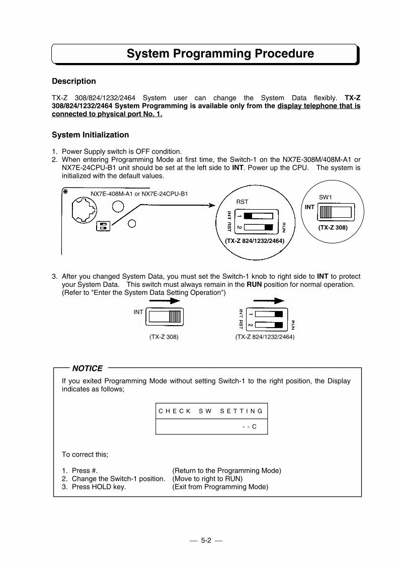
5-2
System Programming Procedure
Description
TX-Z 308/824/1232/2464 System user can change the System Data flexibly. TX-Z308/824/1232/2464 System Programming is available only from the display telephone that isconnected to physical port No. 1.
System Initialization
1. Power Supply switch is OFF condition.2. When entering Programming Mode at first time, the Switch-1 on the NX7E-308M/408M-A1 or
NX7E-24CPU-B1 unit should be set at the left side to INT. Power up the CPU. The system isinitialized with the default values.
3. After you changed System Data, you must set the Switch-1 knob to right side to INT to protectyour System Data. This switch must always remain in the RUN position for normal operation.(Refer to "Enter the System Data Setting Operation")
NOTICE
If you exited Programming Mode without setting Switch-1 to the right position, the Displayindicates as follows;
C H E C K # S W # S E T T I N G
# # # # # # # # # # # # # - - C
To correct this;
1. Press #. (Return to the Programming Mode)2. Change the Switch-1 position. (Move to right to RUN)3. Press HOLD key. (Exit from Programming Mode)
(TX-Z 824/1232/2464)
RSTNX7E-408M-A1 or NX7E-24CPU-B1
(TX-Z 308)
INT
SW1
(TX-Z 308) (TX-Z 824/1232/2464)
INT
5-3
System Programming Procedure
System Reset
Switch-2 (RST/RUN) is used to System Reset for TX-Z 824 & 1232/2464 system. Move the switchto RST (the left) to reset the system immediately, keeping the current program.
However, Reset switch is not available for TX-Z 308 system. To reset TX-Z 308, disconnect the ACplug and replace while the SW1 is on the other side of INT.
Connecting Single Line Telephone
TX-Z 308/824/1232/2464 system can connect Single Line Telephones (SLTs) without changing thehardware but can not recognize the instrument type by only connecting the SLT. When you connectthe SLT first time, you must operate as follows so that system can recognize.
- Method-1: Off-Hook and Hang up. (Once)- Method-2: On the Program #13-E, assign "1 => Connected".
In the each case, when SLT is disconnected, you have to assign the "0 => Not connected" inProgram #13-E.
Entering the System Data Programming
1. (On-Hook Condition) Press OPAC key.2. Dial #, ∗, #, ∗ and Password (8 digits).3. Press HOLD key.
Password can be changed in Program #92. Password's digits are optional from 1 to 8 digits long,and digits between 0 and 9.When you forgot password, you can use Special Password to enter the System Data set up mode.
Key Institution
0 - 9: Enter Program number, Extension number, Trunk number and Option number, etc.∗: Go to next item.#: Exit from current program number.
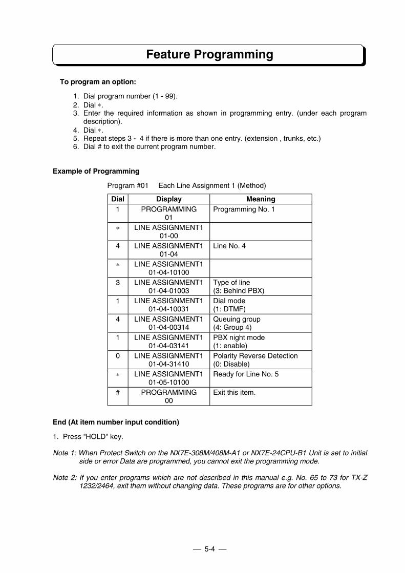
5-4
Feature Programming
To program an option:
1. Dial program number (1 - 99).2. Dial ∗.3. Enter the required information as shown in programming entry. (under each program
description).4. Dial ∗.5. Repeat steps 3 - 4 if there is more than one entry. (extension , trunks, etc.)6. Dial # to exit the current program number.
Example of Programming
Program #01 Each Line Assignment 1 (Method)
Dial Display Meaning1 PROGRAMMING
01Programming No. 1
∗ LINE ASSIGNMENT101-00
4 LINE ASSIGNMENT101-04
Line No. 4
∗ LINE ASSIGNMENT101-04-10100
3 LINE ASSIGNMENT101-04-01003
Type of line(3: Behind PBX)
1 LINE ASSIGNMENT101-04-10031
Dial mode(1: DTMF)
4 LINE ASSIGNMENT101-04-00314
Queuing group(4: Group 4)
1 LINE ASSIGNMENT101-04-03141
PBX night mode(1: enable)
0 LINE ASSIGNMENT101-04-31410
Polarity Reverse Detection(0: Disable)
∗ LINE ASSIGNMENT101-05-10100
Ready for Line No. 5
# PROGRAMMING00
Exit this item.
End (At item number input condition)
1. Press "HOLD" key.
Note 1: When Protect Switch on the NX7E-308M/408M-A1 or NX7E-24CPU-B1 Unit is set to initialside or error Data are programmed, you cannot exit the programming mode.
Note 2: If you enter programs which are not described in this manual e.g. No. 65 to 73 for TX-Z1232/2464, exit them without changing data. These programs are for other options.
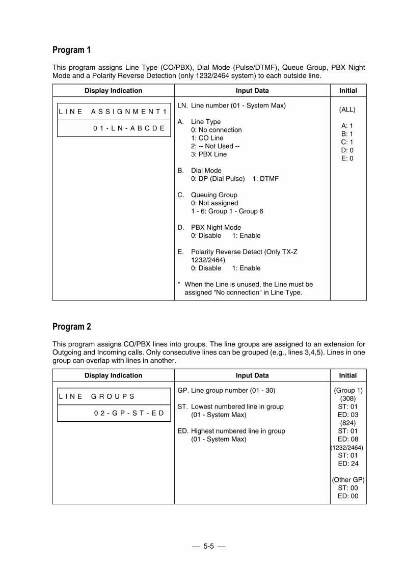
5-5
Program 1This program assigns Line Type (CO/PBX), Dial Mode (Pulse/DTMF), Queue Group, PBX NightMode and a Polarity Reverse Detection (only 1232/2464 system) to each outside line.
Display Indication Input Data Initial
L I N E # A S S I G N M E N T 1
# # # # # 0 1 - L N - A B C D E
LN. Line number (01 - System Max)
A. Line Type0: No connection1: CO Line2: -- Not Used --3: PBX Line
B. Dial Mode0: DP (Dial Pulse) 1: DTMF
C. Queuing Group0: Not assigned1 - 6: Group 1 - Group 6
D. PBX Night Mode0: Disable 1: Enable
E. Polarity Reverse Detect (Only TX-Z1232/2464)0: Disable 1: Enable
* When the Line is unused, the Line must beassigned "No connection" in Line Type.
(ALL)
A: 1B: 1C: 1D: 0E: 0
Program 2This program assigns CO/PBX lines into groups. The line groups are assigned to an extension forOutgoing and Incoming calls. Only consecutive lines can be grouped (e.g., lines 3,4,5). Lines in onegroup can overlap with lines in another.
Display Indication Input Data Initial
L I N E # G R O U P S # # # # #
# # # # # 0 2 - G P - S T - E D
GP. Line group number (01 - 30)
ST. Lowest numbered line in group(01 - System Max)
ED. Highest numbered line in group(01 - System Max)
(Group 1)(308)
ST: 01ED: 03(824)
ST: 01ED: 08
(1232/2464)ST: 01ED: 24
(Other GP)ST: 00ED: 00
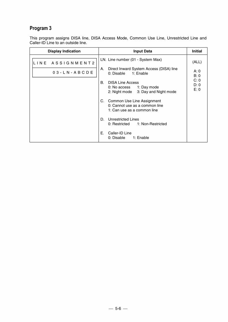
5-6
Program 3This program assigns DISA line, DISA Access Mode, Common Use Line, Unrestricted Line andCaller-ID Line to an outside line.
Display Indication Input Data Initial
L I N E # A S S I G N M E N T 2
# # # # # 0 3 - L N - A B C D E
LN. Line number (01 - System Max)
A. Direct Inward System Access (DISA) line0: Disable 1: Enable
B. DISA Line Access0: No access 1: Day mode2: Night mode 3: Day and Night mode
C. Common Use Line Assignment0: Cannot use as a common line1: Can use as a common line
D. Unrestricted Lines0: Restricted 1: Non-Restricted
E. Caller-ID Line0: Disable 1: Enable
(ALL)
A: 0B: 0C: 0D: 0E: 0
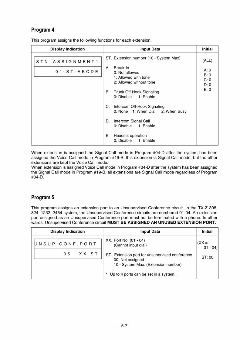
5-7
Program 4This program assigns the following functions for each extension.
Display Indication Input Data Initial
S T N # A S S I G N M E N T 1
# # # # # 0 4 - S T - A B C D E
ST. Extension number (10 - System Max)
A. Break-In0: Not allowed1: Allowed with tone2: Allowed without tone
B. Trunk Off-Hook Signaling0: Disable 1: Enable
C. Intercom Off-Hook Signaling0: None 1: When Dial 2: When Busy
D. Intercom Signal Call0: Disable 1: Enable
E. Headset operation0: Disable 1: Enable
(ALL)
A: 0B: 0C: 0D: 0E: 0
When extension is assigned the Signal Call mode in Program #04-D after the system has beenassigned the Voice Call mode in Program #19-B, this extension is Signal Call mode, but the otherextensions are kept the Voice Call mode.When extension is assigned Voice Call mode in Program #04-D after the system has been assignedthe Signal Call mode in Program #19-B, all extensions are Signal Call mode regardless of Program#04-D.
Program 5This program assigns an extension port to an Unsupervised Conference circuit. In the TX-Z 308,824, 1232, 2464 system, the Unsupervised Conference circuits are numbered 01-04. An extensionport assigned as an Unsupervised Conference port must not be terminated with a phone. In otherwards, Unsupervised Conference circuit MUST BE ASSIGNED AN UNUSED EXTENSION PORT.
Display Indication Input Data Initial
U N S U P . C O N F . P O R T #
# # # # # # # 0 5 # # X X - S T
XX. Port No. (01 - 04)(Cannot input dial)
ST. Extension port for unsupervised conference00: Not assigned10 - System Max: (Extension number)
* Up to 4 ports can be set in a system.
(XX =01 - 04)
ST: 00
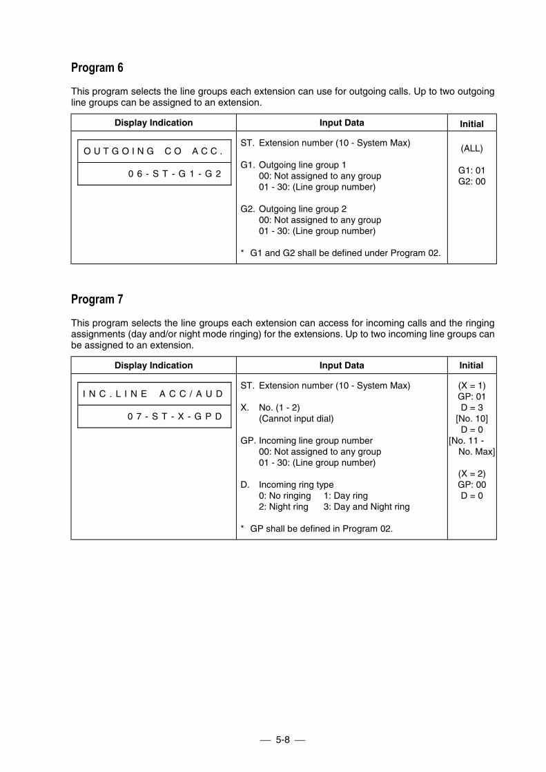
5-8
Program 6This program selects the line groups each extension can use for outgoing calls. Up to two outgoingline groups can be assigned to an extension.
Display Indication Input Data Initial
O U T G O I N G # C O # A C C .
# # # # # 0 6 - S T - G 1 - G 2
ST. Extension number (10 - System Max)
G1. Outgoing line group 100: Not assigned to any group01 - 30: (Line group number)
G2. Outgoing line group 200: Not assigned to any group01 - 30: (Line group number)
* G1 and G2 shall be defined under Program 02.
(ALL)
G1: 01G2: 00
Program 7This program selects the line groups each extension can access for incoming calls and the ringingassignments (day and/or night mode ringing) for the extensions. Up to two incoming line groups canbe assigned to an extension.
Display Indication Input Data Initial
I N C . L I N E # A C C / A U D
# # # # # 0 7 - S T - X - G P D
ST. Extension number (10 - System Max)
X. No. (1 - 2)(Cannot input dial)
GP. Incoming line group number00: Not assigned to any group01 - 30: (Line group number)
D. Incoming ring type0: No ringing 1: Day ring2: Night ring 3: Day and Night ring
* GP shall be defined in Program 02.
(X = 1)GP: 01D = 3
[No. 10]D = 0
[No. 11 -No. Max]
(X = 2)GP: 00D = 0
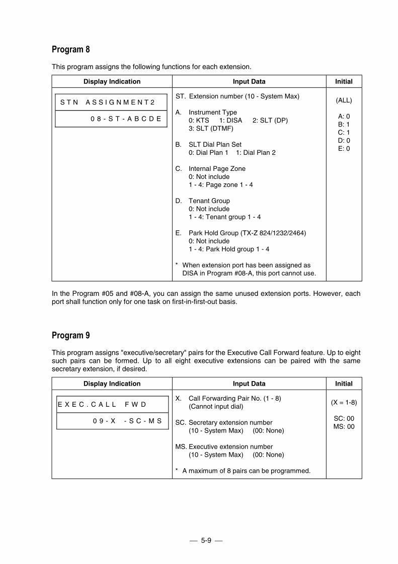
5-9
Program 8This program assigns the following functions for each extension.
Display Indication Input Data Initial
S T N # A S S I G N M E N T 2 #
# # # # # 0 8 - S T - A B C D E
ST. Extension number (10 - System Max)
A. Instrument Type0: KTS 1: DISA 2: SLT (DP)3: SLT (DTMF)
B. SLT Dial Plan Set0: Dial Plan 1 1: Dial Plan 2
C. Internal Page Zone0: Not include1 - 4: Page zone 1 - 4
D. Tenant Group0: Not include1 - 4: Tenant group 1 - 4
E. Park Hold Group (TX-Z 824/1232/2464)0: Not include1 - 4: Park Hold group 1 - 4
* When extension port has been assigned asDISA in Program #08-A, this port cannot use.
(ALL)
A: 0B: 1C: 1D: 0E: 0
In the Program #05 and #08-A, you can assign the same unused extension ports. However, eachport shall function only for one task on first-in-first-out basis.
Program 9This program assigns "executive/secretary" pairs for the Executive Call Forward feature. Up to eightsuch pairs can be formed. Up to all eight executive extensions can be paired with the samesecretary extension, if desired.
Display Indication Input Data Initial
E X E C . C A L L # F W D # # #
# # # # # 0 9 - X # - S C - M S
X. Call Forwarding Pair No. (1 - 8)(Cannot input dial)
SC. Secretary extension number(10 - System Max) (00: None)
MS. Executive extension number(10 - System Max) (00: None)
* A maximum of 8 pairs can be programmed.
(X = 1-8)
SC: 00MS: 00
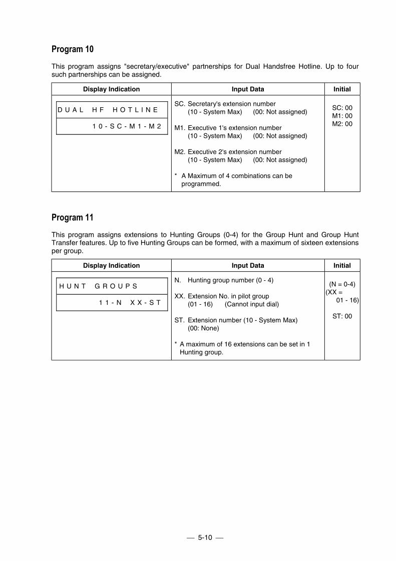
5-10
Program 10This program assigns "secretary/executive" partnerships for Dual Handsfree Hotline. Up to foursuch partnerships can be assigned.
Display Indication Input Data Initial
D U A L # H F # H O T L I N E #
# # # # # 1 0 - S C - M 1 - M 2
SC. Secretary's extension number(10 - System Max) (00: Not assigned)
M1. Executive 1's extension number(10 - System Max) (00: Not assigned)
M2. Executive 2's extension number(10 - System Max) (00: Not assigned)
* A Maximum of 4 combinations can beprogrammed.
SC: 00M1: 00M2: 00
Program 11This program assigns extensions to Hunting Groups (0-4) for the Group Hunt and Group HuntTransfer features. Up to five Hunting Groups can be formed, with a maximum of sixteen extensionsper group.
Display Indication Input Data Initial
H U N T # G R O U P S # # # #
# # # # # # 1 1 - N # X X - S T
N. Hunting group number (0 - 4)
XX. Extension No. in pilot group(01 - 16) (Cannot input dial)
ST. Extension number (10 - System Max)(00: None)
* A maximum of 16 extensions can be set in 1Hunting group.
(N = 0-4)(XX =
01 - 16)
ST: 00
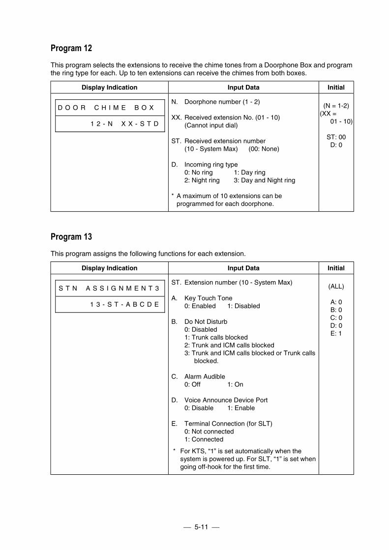
5-11
Program 12This program selects the extensions to receive the chime tones from a Doorphone Box and programthe ring type for each. Up to ten extensions can receive the chimes from both boxes.
Display Indication Input Data Initial
D O O R # C H I M E # B O X #
# # # # # 1 2 - N # X X - S T D
N. Doorphone number (1 - 2)
XX. Received extension No. (01 - 10)(Cannot input dial)
ST. Received extension number(10 - System Max) (00: None)
D. Incoming ring type0: No ring 1: Day ring2: Night ring 3: Day and Night ring
* A maximum of 10 extensions can beprogrammed for each doorphone.
(N = 1-2)(XX =
01 - 10)
ST: 00D: 0
Program 13This program assigns the following functions for each extension.
Display Indication Input Data Initial
S T N # A S S I G N M E N T 3
# # # # # 1 3 - S T - A B C D E
ST. Extension number (10 - System Max)
A. Key Touch Tone0: Enabled 1: Disabled
B. Do Not Disturb0: Disabled1: Trunk calls blocked2: Trunk and ICM calls blocked3: Trunk and ICM calls blocked or Trunk calls blocked.
C. Alarm Audible0: Off 1: On
D. Voice Announce Device Port0: Disable 1: Enable
E. Terminal Connection (for SLT)0: Not connected1: Connected
* For KTS, “1” is set automatically when thesystem is powered up. For SLT, “1” is set whengoing off-hook for the first time.
(ALL)
A: 0B: 0C: 0D: 0E: 1
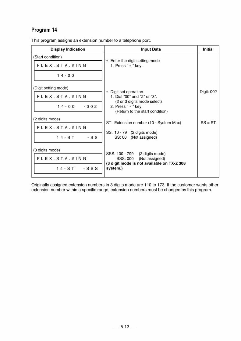
5-12
Program 14This program assigns an extension number to a telephone port.
Display Indication Input Data Initial
(Start condition)
F L E X . S T A . # I N G # # #
# # # # # 1 4 - 0 0 # # # # # #
∗ Enter the digit setting mode1. Press " ∗ " key.
(Digit setting mode)
F L E X . S T A . # I N G # # #
# # # # # 1 4 - 0 0 # # - 0 0 2
∗ Digit set operation1. Dial "00" and "2" or "3".
(2 or 3 digits mode select)2. Press " ∗ " key.
(Return to the start condition)
Digit: 002
(2 digits mode)
F L E X . S T A . # I N G # # #
# # # # # 1 4 - S T # # # - S S
ST. Extension number (10 - System Max)
SS. 10 - 79 (2 digits mode)SS: 00 (Not assigned)
SS = ST
(3 digits mode)
F L E X . S T A . # I N G # # #
# # # # # 1 4 - S T # # - S S S
SSS. 100 - 799 (3 digits mode)SSS: 000 (Not assigned)
(3 digit mode is not available on TX-Z 308system.)
Originally assigned extension numbers in 3 digits mode are 110 to 173. If the customer wants otherextension number within a specific range, extension numbers must be changed by this program.
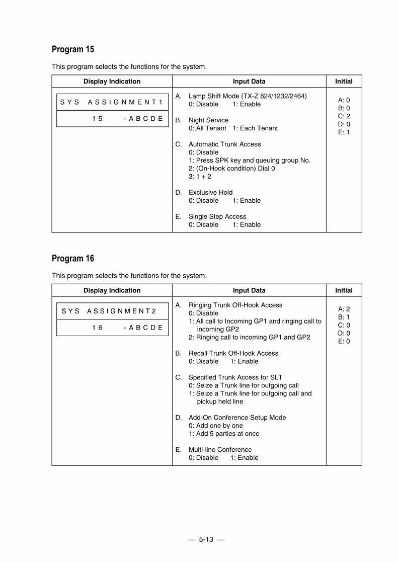
5-13
Program 15This program selects the functions for the system.
Display Indication Input Data Initial
S Y S # A S S I G N M E N T 1
# # # # # 1 5 # # # - A B C D E
A. Lamp Shift Mode (TX-Z 824/1232/2464)0: Disable 1: Enable
B. Night Service0: All Tenant 1: Each Tenant
C. Automatic Trunk Access0: Disable1: Press SPK key and queuing group No.2: (On-Hook condition) Dial 03: 1 + 2
D. Exclusive Hold0: Disable 1: Enable
E. Single Step Access0: Disable 1: Enable
A: 0B: 0C: 2D: 0E: 1
Program 16This program selects the functions for the system.
Display Indication Input Data Initial
S Y S # A S S I G N M E N T 2 #
# # # # # 1 6 # # # - A B C D E
A. Ringing Trunk Off-Hook Access0: Disable1: All call to Incoming GP1 and ringing call to
incoming GP22: Ringing call to incoming GP1 and GP2
B. Recall Trunk Off-Hook Access0: Disable 1: Enable
C. Specified Trunk Access for SLT0: Seize a Trunk line for outgoing call1: Seize a Trunk line for outgoing call and
pickup held line
D. Add-On Conference Setup Mode0: Add one by one1: Add 5 parties at once
E. Multi-line Conference0: Disable 1: Enable
A: 2B: 1C: 0D: 0E: 0
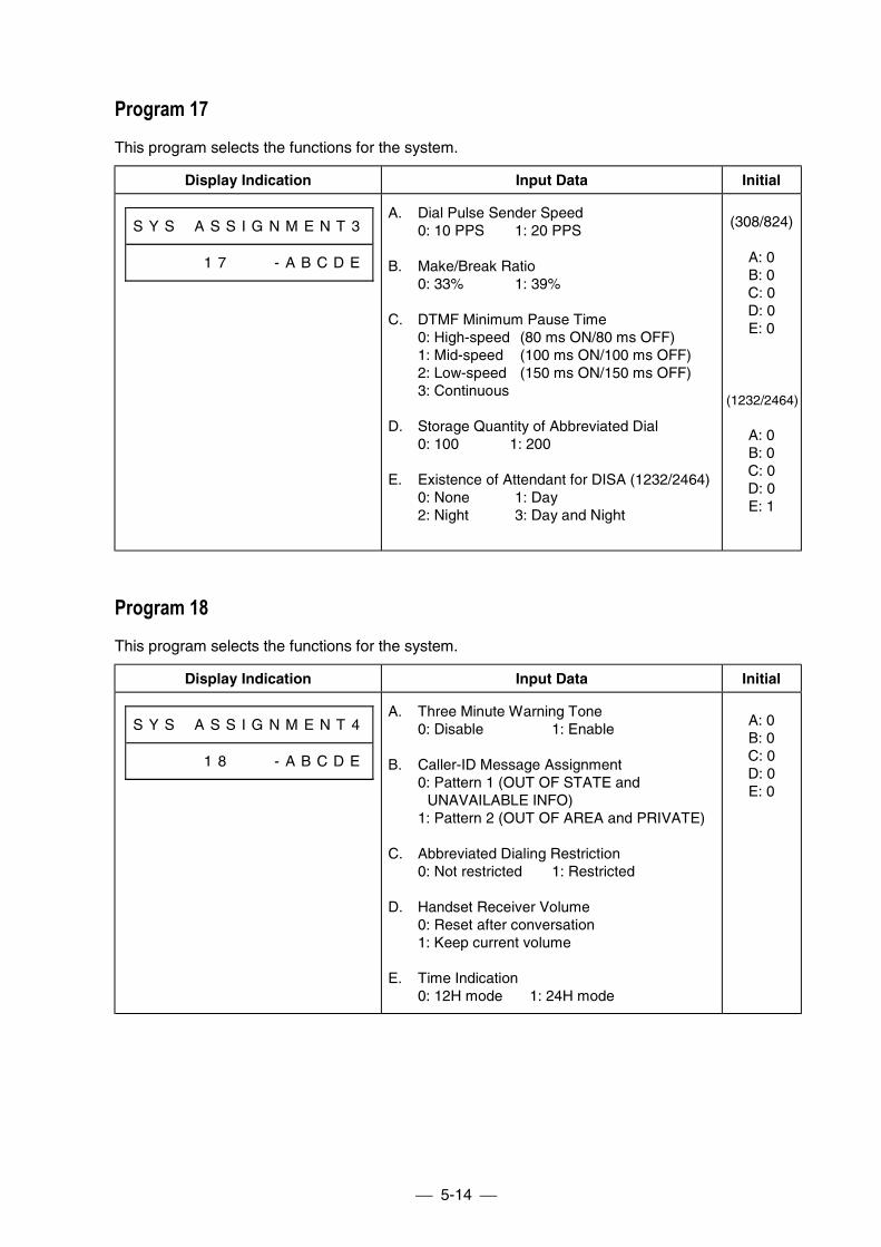
5-14
Program 17This program selects the functions for the system.
Display Indication Input Data Initial
S Y S # A S S I G N M E N T 3
# # # # # 1 7 # # # - A B C D E
A. Dial Pulse Sender Speed0: 10 PPS 1: 20 PPS
B. Make/Break Ratio0: 33% 1: 39%
C. DTMF Minimum Pause Time0: High-speed (80 ms ON/80 ms OFF)1: Mid-speed (100 ms ON/100 ms OFF)2: Low-speed (150 ms ON/150 ms OFF)3: Continuous
D. Storage Quantity of Abbreviated Dial0: 100 1: 200
E. Existence of Attendant for DISA (1232/2464)0: None 1: Day2: Night 3: Day and Night
(308/824)
A: 0B: 0C: 0D: 0E: 0
(1232/2464)
A: 0B: 0C: 0D: 0E: 1
Program 18This program selects the functions for the system.
Display Indication Input Data Initial
S Y S # A S S I G N M E N T 4
# # # # # 1 8 # # # - A B C D E
A. Three Minute Warning Tone0: Disable 1: Enable
B. Caller-ID Message Assignment0: Pattern 1 (OUT OF STATE and
UNAVAILABLE INFO)1: Pattern 2 (OUT OF AREA and PRIVATE)
C. Abbreviated Dialing Restriction0: Not restricted 1: Restricted
D. Handset Receiver Volume0: Reset after conversation1: Keep current volume
E. Time Indication0: 12H mode 1: 24H mode
A: 0B: 0C: 0D: 0E: 0
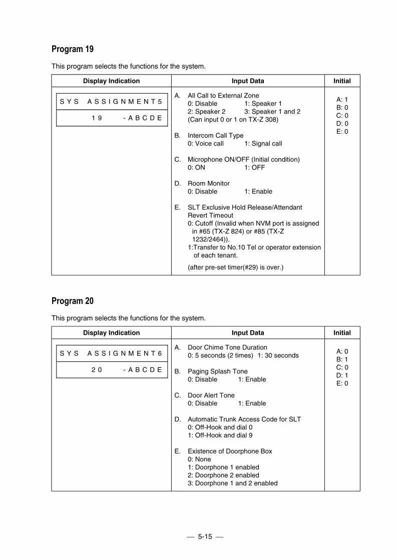
5-15
Program 19This program selects the functions for the system.
Display Indication Input Data Initial
S Y S # A S S I G N M E N T 5
# # # # # 1 9 # # # - A B C D E
A. All Call to External Zone0: Disable 1: Speaker 12: Speaker 2 3: Speaker 1 and 2(Can input 0 or 1 on TX-Z 308)
B. Intercom Call Type0: Voice call 1: Signal call
C. Microphone ON/OFF (Initial condition)0: ON 1: OFF
D. Room Monitor0: Disable 1: Enable
E. SLT Exclusive Hold Release/AttendantRevert Timeout0: Cutoff (Invalid when NVM port is assigned
in #65 (TX-Z 824) or #85 (TX-Z1232/2464)).
1:Transfer to No.10 Tel or operator extension of each tenant.
(after pre-set timer(#29) is over.)
A: 1B: 0C: 0D: 0E: 0
Program 20This program selects the functions for the system.
Display Indication Input Data Initial
S Y S # A S S I G N M E N T 6
# # # # # 2 0 # # # - A B C D E
A. Door Chime Tone Duration0: 5 seconds (2 times) 1: 30 seconds
B. Paging Splash Tone0: Disable 1: Enable
C. Door Alert Tone0: Disable 1: Enable
D. Automatic Trunk Access Code for SLT0: Off-Hook and dial 01: Off-Hook and dial 9
E. Existence of Doorphone Box0: None1: Doorphone 1 enabled2: Doorphone 2 enabled3: Doorphone 1 and 2 enabled
A: 0B: 1C: 0D: 1E: 0
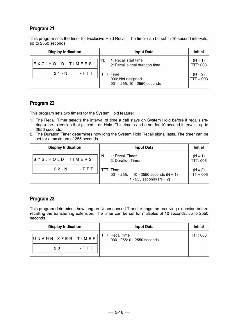
5-16
Program 21This program sets the timer for Exclusive Hold Recall. The timer can be set in 10 second intervals,up to 2550 seconds.
Display Indication Input Data Initial
E X C . H O L D # T I M E R S #
# # # # # 2 1 - N # # # - T T T
N. 1: Recall start time2: Recall signal duration time
TTT. Time000: Not assigned001 - 255: 10 - 2550 seconds
(N = 1)TTT: 003
(N = 2)TTT = 003
Program 22This program sets two timers for the System Hold feature:
1. The Recall Timer selects the interval of time a call stays on System Hold before it recalls (re-rings) the extension that placed it on Hold. This timer can be set for 10 second intervals, up to2550 seconds.
2. The Duration Timer determines how long the System Hold Recall signal lasts. The timer can beset for a maximum of 255 seconds.
Display Indication Input Data Initial
S Y S . H O L D # T I M E R S #
# # # # # 2 2 - N # # # - T T T
N. 1: Recall Timer2: Duration Timer
TTT. Time001 - 255: 10 - 2550 seconds (N = 1)
1 - 255 seconds (N = 2)
(N = 1)TTT: 006
(N = 2)TTT = 005
Program 23This program determines how long an Unannounced Transfer rings the receiving extension beforerecalling the transferring extension. The timer can be set for multiples of 10 seconds, up to 2550seconds.
Display Indication Input Data Initial
U N A N N . X F E R # T I M E R
# # # # # 2 3 # # # # # - T T T
TTT. Recall time000 - 255: 0 - 2550 seconds
TTT: 006
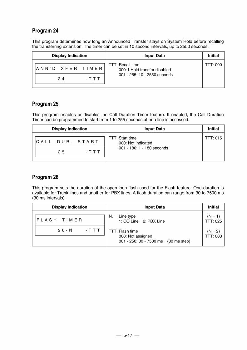
5-17
Program 24This program determines how long an Announced Transfer stays on System Hold before recallingthe transferring extension. The timer can be set in 10 second intervals, up to 2550 seconds.
Display Indication Input Data Initial
A N N ' D # X F E R # T I M E R
# # # # # 2 4 # # # # # - T T T
TTT. Recall time000: I-Hold transfer disabled001 - 255: 10 - 2550 seconds
TTT: 000
Program 25This program enables or disables the Call Duration Timer feature. If enabled, the Call DurationTimer can be programmed to start from 1 to 255 seconds after a line is accessed.
Display Indication Input Data Initial
C A L L # D U R . # S T A R T #
# # # # # 2 5 # # # # # - T T T
TTT. Start time000: Not indicated001 - 180: 1 - 180 seconds
TTT: 015
Program 26This program sets the duration of the open loop flash used for the Flash feature. One duration isavailable for Trunk lines and another for PBX lines. A flash duration can range from 30 to 7500 ms(30 ms intervals).
Display Indication Input Data Initial
F L A S H # T I M E R # # # # #
# # # # # 2 6 - N # # # - T T T
N. Line type1: CO Line 2: PBX Line
TTT. Flash time000: Not assigned001 - 250: 30 - 7500 ms (30 ms step)
(N = 1)TTT: 025
(N = 2)TTT: 003
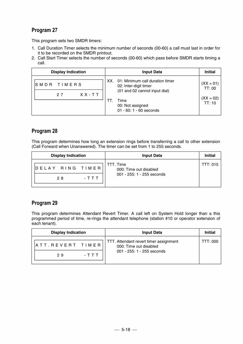
5-18
Program 27This program sets two SMDR timers:
1. Call Duration Timer selects the minimum number of seconds (00-60) a call must last in order forit to be recorded on the SMDR printout.
2. Call Start Timer selects the number of seconds (00-60) which pass before SMDR starts timing acall.
Display Indication Input Data Initial
S M D R # T I M E R S # # # # #
# # # # # 2 7 # # # # X X - T T
XX. 01: Minimum call duration timer02: Inter-digit timer(01 and 02 cannot input dial)
TT. Time00: Not assigned01 - 60: 1 - 60 seconds
(XX = 01)TT: 00
(XX = 02)TT: 10
Program 28This program determines how long an extension rings before transferring a call to other extension(Call Forward when Unanswered). The timer can be set from 1 to 255 seconds.
Display Indication Input Data Initial
D E L A Y # R I N G # T I M E R
# # # # # 2 8 # # # # # - T T T
TTT. Time000: Time out disabled001 - 255: 1 - 255 seconds
TTT: 015
Program 29This program determines Attendant Revert Timer. A call left on System Hold longer than a thisprogrammed period of time, re-rings the attendant telephone (station #10 or operator extension ofeach tenant).
Display Indication Input Data Initial
A T T . R E V E R T # T I M E R
# # # # # 2 9 # # # # # - T T T
TTT. Attendant revert timer assignment000: Time out disabled001 - 255: 1 - 255 seconds
TTT: 000
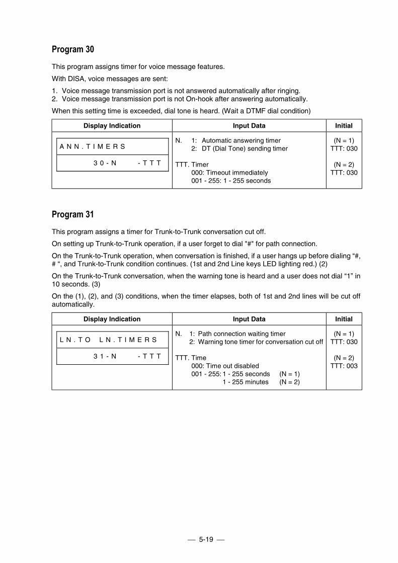
5-19
Program 30This program assigns timer for voice message features.
With DISA, voice messages are sent:
1. Voice message transmission port is not answered automatically after ringing.2. Voice message transmission port is not On-hook after answering automatically.
When this setting time is exceeded, dial tone is heard. (Wait a DTMF dial condition)
Display Indication Input Data Initial
A N N . T I M E R S # # # # # #
# # # # # 3 0 - N # # # - T T T
N. 1: Automatic answering timer2: DT (Dial Tone) sending timer
TTT. Timer000: Timeout immediately001 - 255: 1 - 255 seconds
(N = 1)TTT: 030
(N = 2)TTT: 030
Program 31This program assigns a timer for Trunk-to-Trunk conversation cut off.
On setting up Trunk-to-Trunk operation, if a user forget to dial "#" for path connection.
On the Trunk-to-Trunk operation, when conversation is finished, if a user hangs up before dialing “#,# “, and Trunk-to-Trunk condition continues. (1st and 2nd Line keys LED lighting red.) (2)
On the Trunk-to-Trunk conversation, when the warning tone is heard and a user does not dial “1” in10 seconds. (3)
On the (1), (2), and (3) conditions, when the timer elapses, both of 1st and 2nd lines will be cut offautomatically.
Display Indication Input Data Initial
L N . T O # L N . T I M E R S #
# # # # # 3 1 - N # # # - T T T
N. 1: Path connection waiting timer2: Warning tone timer for conversation cut off
TTT. Time000: Time out disabled001 - 255: 1 - 255 seconds (N = 1)
1 - 255 minutes (N = 2)
(N = 1)TTT: 030
(N = 2)TTT: 003
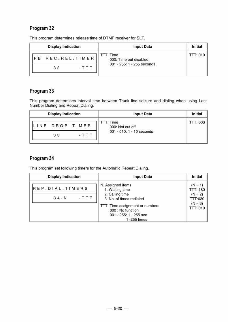
5-20
Program 32This program determines release time of DTMF receiver for SLT.
Display Indication Input Data Initial
P B # R E C . R E L . T I M E R
# # # # # 3 2 # # # # # - T T T
TTT. Time000: Time out disabled001 - 255: 1 - 255 seconds
TTT: 010
Program 33This program determines interval time between Trunk line seizure and dialing when using LastNumber Dialing and Repeat Dialing.
Display Indication Input Data Initial
L I N E # D R O P # T I M E R #
# # # # # 3 3 # # # # # - T T T
TTT. Time000: Not cut off001 - 010: 1 - 10 seconds
TTT: 003
Program 34This program set following timers for the Automatic Repeat Dialing.
Display Indication Input Data Initial
R E P . D I A L . T I M E R S # #
# # # # # 3 4 - N # # # - T T T
N. Assigned items1. Waiting time2. Calling time3. No. of times redialed
TTT. Time assignment or numbers000 : No function001 - 255: 1 - 255 sec
1 -255 times
(N = 1)TTT: 180(N = 2)
TTT:030(N = 3)
TTT: 010
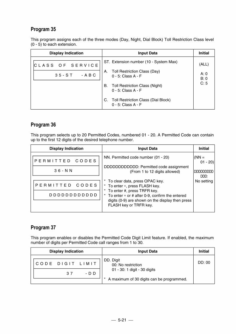
5-21
Program 35This program assigns each of the three modes (Day, Night, Dial Block) Toll Restriction Class level(0 - 5) to each extension.
Display Indication Input Data Initial
C L A S S # O F # S E R V I C E
# # # # # 3 5 - S T # # - A B C
ST. Extension number (10 - System Max)
A. Toll Restriction Class (Day)0 - 5: Class A - F
B. Toll Restriction Class (Night)0 - 5: Class A - F
C. Toll Restriction Class (Dial Block)0 - 5: Class A - F
(ALL)
A: 0B: 0C: 5
Program 36This program selects up to 20 Permitted Codes, numbered 01 - 20. A Permitted Code can containup to the first 12 digits of the desired telephone number.
Display Indication Input Data Initial
P E R M I T T E D # C O D E S
# # # # # 3 6 - N N # # # # # #
P E R M I T T E D # C O D E S
# # # # D D D D D D D D D D D D
NN. Permitted code number (01 - 20)
DDDDDDDDDDDD: Permitted code assignment(From 1 to 12 digits allowed)
* To clear data, press OPAC key.* To enter ∗, press FLASH key.* To enter #, press TRFR key.* To enter ∗ or # after 0-9, confirm the entered
digits (0-9) are shown on the display then pressFLASH key or TRFR key.
(NN =01 - 20)
DDDDDDDDDDDD:
No setting
Program 37This program enables or disables the Permitted Code Digit Limit feature. If enabled, the maximumnumber of digits per Permitted Code call ranges from 1 to 30.
Display Indication Input Data Initial
C O D E # D I G I T # L I M I T
# # # # # # # # 3 7 # # # - D D
DD. Digit00: No restriction01 - 30: 1 digit - 30 digits
* A maximum of 30 digits can be programmed.
DD: 00
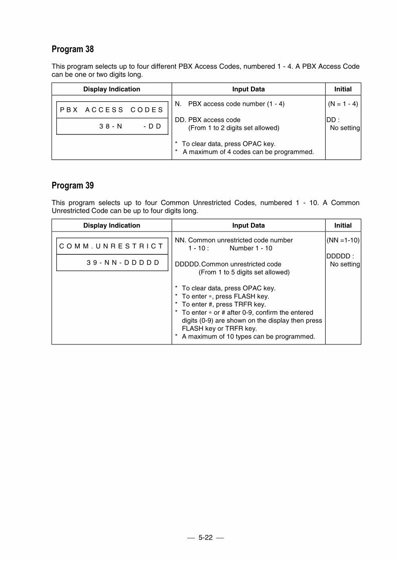
5-22
Program 38This program selects up to four different PBX Access Codes, numbered 1 - 4. A PBX Access Codecan be one or two digits long.
Display Indication Input Data Initial
P B X # A C C E S S # C O D E S
# # # # # # 3 8 - N # # # - D D
N. PBX access code number (1 - 4)
DD. PBX access code(From 1 to 2 digits set allowed)
* To clear data, press OPAC key.* A maximum of 4 codes can be programmed.
(N = 1 - 4)
DD :No setting
Program 39This program selects up to four Common Unrestricted Codes, numbered 1 - 10. A CommonUnrestricted Code can be up to four digits long.
Display Indication Input Data Initial
C O M M . U N R E S T R I C T
# # # 3 9 - N N - D D D D D
NN. Common unrestricted code number1 - 10 : Number 1 - 10
DDDDD.Common unrestricted code(From 1 to 5 digits set allowed)
* To clear data, press OPAC key.* To enter ∗, press FLASH key.* To enter #, press TRFR key.* To enter ∗ or # after 0-9, confirm the entered
digits (0-9) are shown on the display then pressFLASH key or TRFR key.
* A maximum of 10 types can be programmed.
(NN =1-10)
DDDDD :No setting
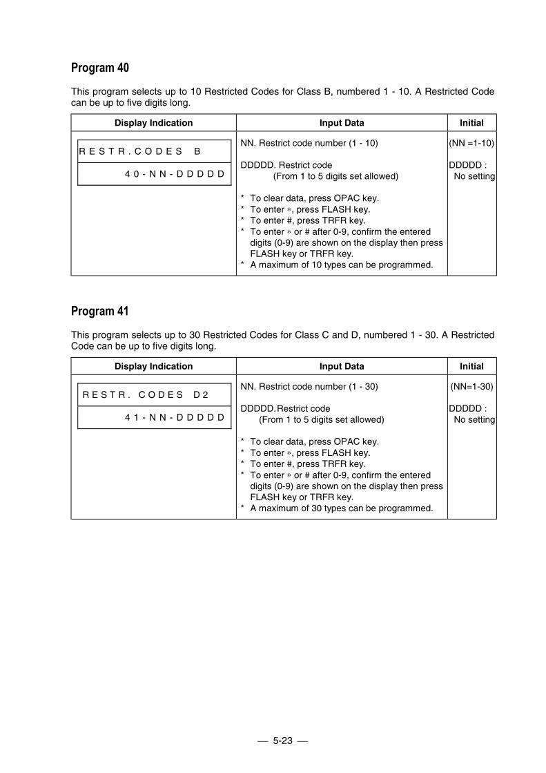
5-23
Program 40This program selects up to 10 Restricted Codes for Class B, numbered 1 - 10. A Restricted Codecan be up to five digits long.
Display Indication Input Data Initial
R E S T R . C O D E S # B # # #
# # # # # 4 0 - N N - D D D D D
NN. Restrict code number (1 - 10)
DDDDD. Restrict code(From 1 to 5 digits set allowed)
* To clear data, press OPAC key.* To enter ∗, press FLASH key.* To enter #, press TRFR key.* To enter ∗ or # after 0-9, confirm the entered
digits (0-9) are shown on the display then pressFLASH key or TRFR key.
* A maximum of 10 types can be programmed.
(NN =1-10)
DDDDD :No setting
Program 41This program selects up to 30 Restricted Codes for Class C and D, numbered 1 - 30. A RestrictedCode can be up to five digits long.
Display Indication Input Data Initial
R E S T R . C O D E S # D 2 # #
# # # # # 4 1 - N N - D D D D D
NN. Restrict code number (1 - 30)
DDDDD.Restrict code(From 1 to 5 digits set allowed)
* To clear data, press OPAC key.* To enter ∗, press FLASH key.* To enter #, press TRFR key.* To enter ∗ or # after 0-9, confirm the entered
digits (0-9) are shown on the display then pressFLASH key or TRFR key.
* A maximum of 30 types can be programmed.
(NN=1-30)
DDDDD :No setting
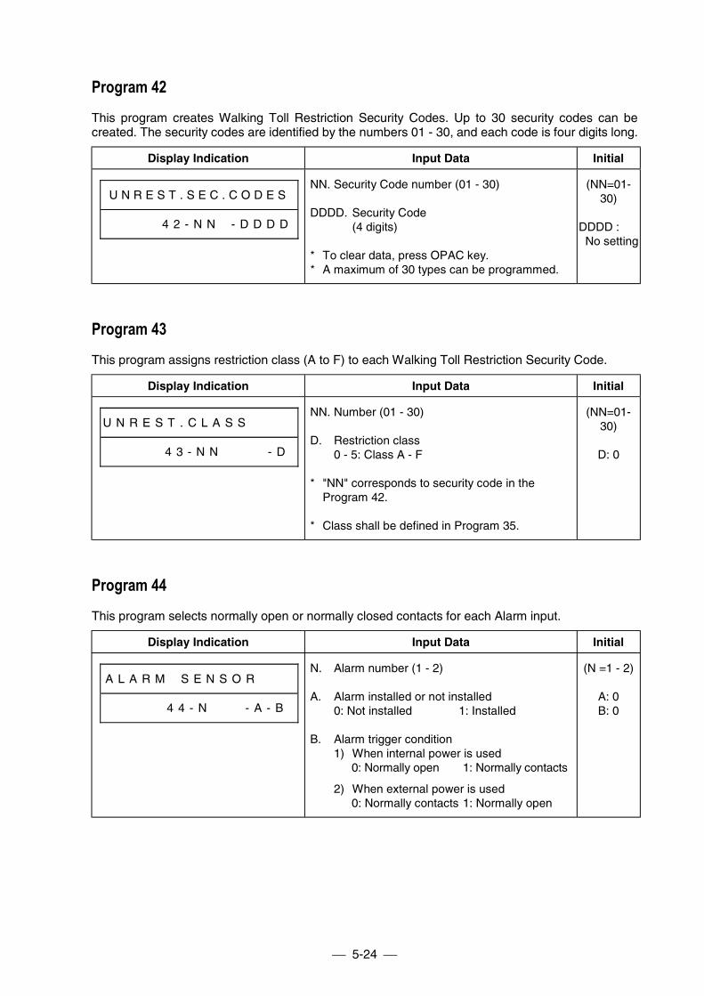
5-24
Program 42This program creates Walking Toll Restriction Security Codes. Up to 30 security codes can becreated. The security codes are identified by the numbers 01 - 30, and each code is four digits long.
Display Indication Input Data Initial
U N R E S T . S E C . C O D E S
# # # # # 4 2 - N N # - D D D D
NN. Security Code number (01 - 30)
DDDD. Security Code(4 digits)
* To clear data, press OPAC key.* A maximum of 30 types can be programmed.
(NN=01-30)
DDDD :No setting
Program 43This program assigns restriction class (A to F) to each Walking Toll Restriction Security Code.
Display Indication Input Data Initial
U N R E S T . C L A S S # # # #
# # # # # 4 3 - N N # # # # - D
NN. Number (01 - 30)
D. Restriction class0 - 5: Class A - F
* "NN" corresponds to security code in theProgram 42.
* Class shall be defined in Program 35.
(NN=01-30)
D: 0
Program 44This program selects normally open or normally closed contacts for each Alarm input.
Display Indication Input Data Initial
A L A R M # S E N S O R # # #
# # # # # 4 4 - N # # # - A - B
N. Alarm number (1 - 2)
A. Alarm installed or not installed0: Not installed 1: Installed
B. Alarm trigger condition1) When internal power is used
0: Normally open 1: Normally contacts
2) When external power is used0: Normally contacts 1: Normally open
(N =1 - 2)
A: 0B: 0
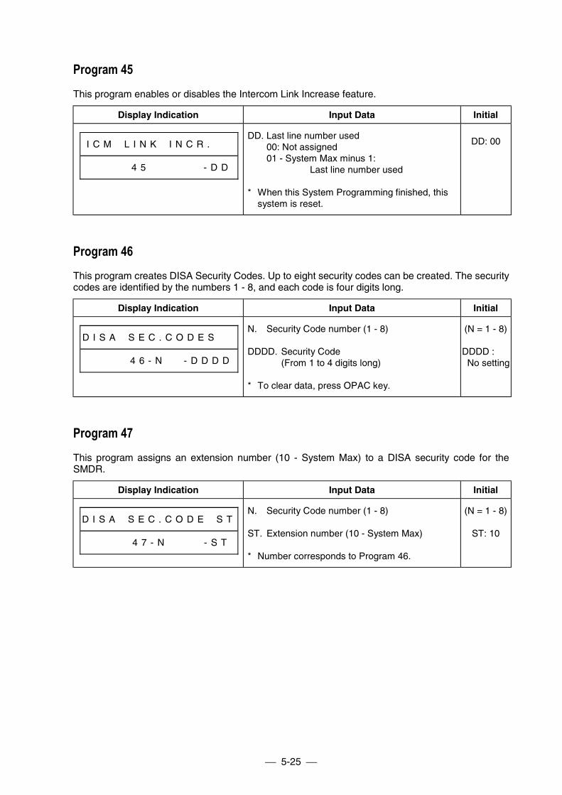
5-25
Program 45This program enables or disables the Intercom Link Increase feature.
Display Indication Input Data Initial
I C M # L I N K # I N C R . # #
# # # # # 4 5 # # # # # # - D D
DD. Last line number used00: Not assigned01 - System Max minus 1:
Last line number used
* When this System Programming finished, thissystem is reset.
DD: 00
Program 46This program creates DISA Security Codes. Up to eight security codes can be created. The securitycodes are identified by the numbers 1 - 8, and each code is four digits long.
Display Indication Input Data Initial
D I S A # S E C . C O D E S # #
# # # # # 4 6 - N # # - D D D D
N. Security Code number (1 - 8)
DDDD. Security Code(From 1 to 4 digits long)
* To clear data, press OPAC key.
(N = 1 - 8)
DDDD :No setting
Program 47This program assigns an extension number (10 - System Max) to a DISA security code for theSMDR.
Display Indication Input Data Initial
D I S A # S E C . C O D E # S T
# # # # # 4 7 - N # # # # - S T
N. Security Code number (1 - 8)
ST. Extension number (10 - System Max)
* Number corresponds to Program 46.
(N = 1 - 8)
ST: 10
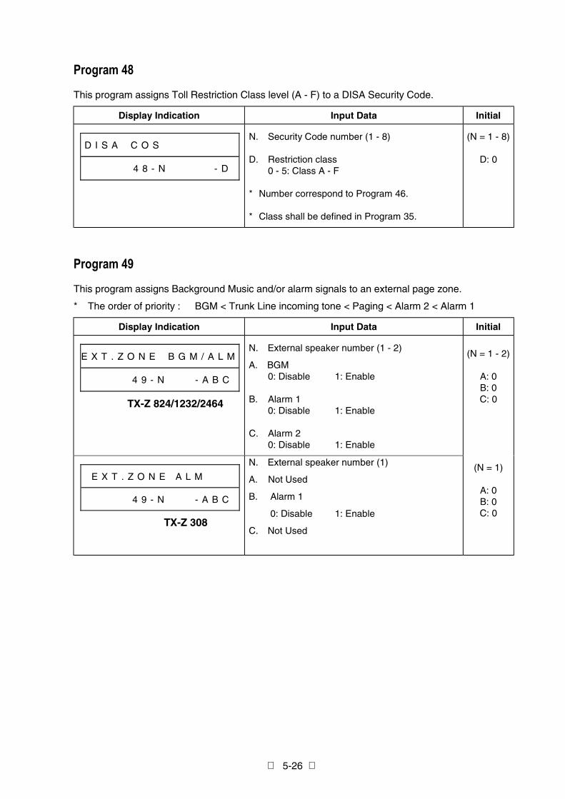
5-26
Program 48
This program assigns Toll Restriction Class level (A - F) to a DISA Security Code.
Display Indication Input Data Initial
D I S A # C O S # # # # # # # #
# # # # # 4 8 - N # # # # # - D
N. Security Code number (1 - 8)
D. Restriction class0 - 5: Class A - F
* Number correspond to Program 46.
* Class shall be defined in Program 35.
(N = 1 - 8)
D: 0
Program 49
This program assigns Background Music and/or alarm signals to an external page zone.
* The order of priority : BGM < Trunk Line incoming tone < Paging < Alarm 2 < Alarm 1
Display Indication Input Data Initial
E X T . Z O N E # B G M / A L M
# # # # # 4 9 - N # # # - A B C
N. External speaker number (1 - 2)
A. BGM0: Disable 1: Enable
B. Alarm 10: Disable 1: Enable
C. Alarm 20: Disable 1: Enable
E X T . Z O N E A L M
# # # # # 4 9 - N # # # - A B C
N. External speaker number (1)
A. Not Used
B. Alarm 1
0: Disable 1: Enable
C. Not Used
(N = 1 - 2)
A: 0B: 0C: 0
(N = 1)
A: 0B: 0C: 0
TX-Z 308
TX-Z 824/1232/2464
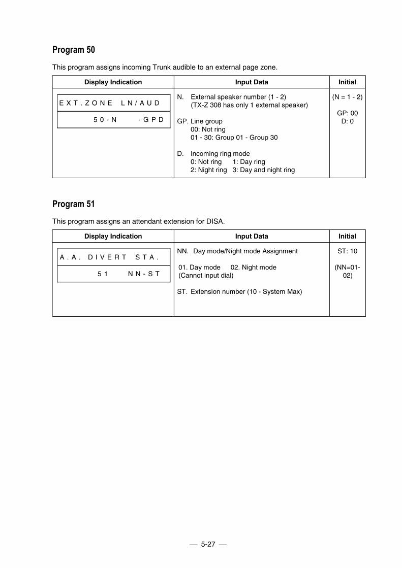
5-27
Program 50This program assigns incoming Trunk audible to an external page zone.
Display Indication Input Data Initial
E X T . Z O N E # L N / A U D #
# # # # # 5 0 - N # # # - G P D
N. External speaker number (1 - 2)(TX-Z 308 has only 1 external speaker)
GP. Line group00: Not ring01 - 30: Group 01 - Group 30
D. Incoming ring mode0: Not ring 1: Day ring2: Night ring 3: Day and night ring
(N = 1 - 2)
GP: 00D: 0
Program 51This program assigns an attendant extension for DISA.
Display Indication Input Data Initial
A . A . D I V E R T # S T A . #
# # # # # 5 1 N N - S T
NN. Day mode/Night mode Assignment
01. Day mode 02. Night mode (Cannot input dial)
ST. Extension number (10 - System Max)
ST: 10
(NN=01-02)
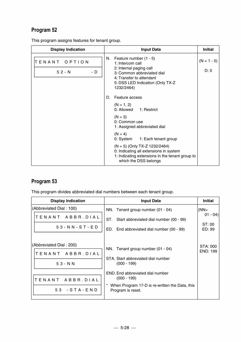
5-28
Program 52This program assigns features for tenant group.
Display Indication Input Data Initial
T E N A N T # O P T I O N # # #
# # # # # 5 2 - N # # # # # - D
N. Feature number (1 - 5)1: Intercom call2: Internal paging call3: Common abbreviated dial4: Transfer to attendant5: DSS LED Indication (Only TX-Z1232/2464)
D. Feature access
(N = 1, 2)0: Allowed 1: Restrict
(N = 3)0: Common use1: Assigned abbreviated dial
(N = 4)0: System 1: Each tenant group
(N = 5) (Only TX-Z 1232/2464)0: Indicating all extensions in system1: Indicating extensions in the tenant group to
which the DSS belongs
(N = 1 - 5)
D: 0
Program 53This program divides abbreviated dial numbers between each tenant group.
Display Indication Input Data Initial
(Abbreviated Dial : 100)
T E N A N T # A B B R . D I A L
# # # # # 5 3 - N N - S T - E D
NN. Tenant group number (01 - 04)
ST. Start abbreviated dial number (00 - 99)
ED. End abbreviated dial number (00 - 99)
(NN=01 - 04)
ST: 00ED: 99
(Abbreviated Dial : 200)
T E N A N T # A B B R . D I A L
# # # # # 5 3 - N N # # # # # #
T E N A N T # A B B R . D I A L
# # # # # 5 3 # - S T A - E N D
NN. Tenant group number (01 - 04)
STA. Start abbreviated dial number(000 - 199)
END. End abbreviated dial number(000 - 199)
* When Program 17-D is re-written the Data, thisProgram is reset.
STA: 000END: 199
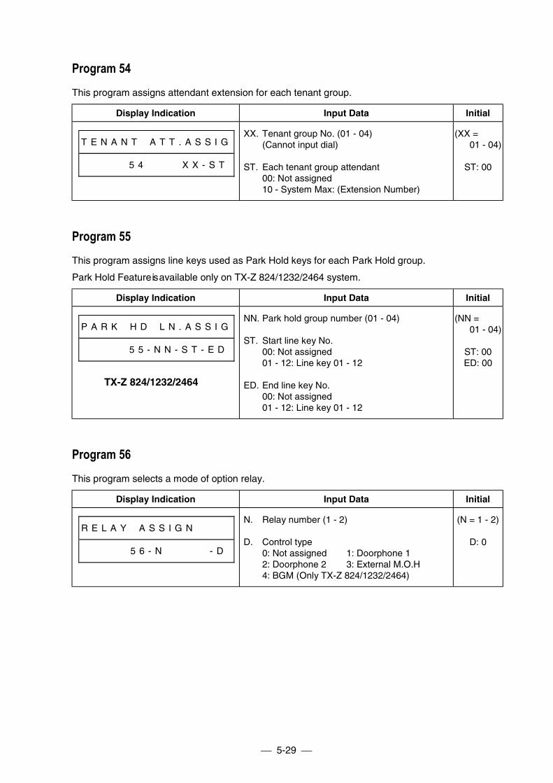
5-29
Program 54This program assigns attendant extension for each tenant group.
Display Indication Input Data Initial
T E N A N T # A T T . A S S I G
# # # # # 5 4 # # # # X X - S T
XX. Tenant group No. (01 - 04)(Cannot input dial)
ST. Each tenant group attendant00: Not assigned10 - System Max: (Extension Number)
(XX =01 - 04)
ST: 00
Program 55This program assigns line keys used as Park Hold keys for each Park Hold group.
Park Hold Feature is available only on TX-Z 824/1232/2464 system.
Display Indication Input Data Initial
P A R K # H D # L N . A S S I G
# # # # # 5 5 - N N - S T - E D
NN. Park hold group number (01 - 04)
ST. Start line key No.00: Not assigned01 - 12: Line key 01 - 12
ED. End line key No.00: Not assigned01 - 12: Line key 01 - 12
(NN =01 - 04)
ST: 00ED: 00
Program 56This program selects a mode of option relay.
Display Indication Input Data Initial
R E L A Y # A S S I G N # # # #
# # # # # 5 6 - N # # # # # - D
N. Relay number (1 - 2)
D. Control type0: Not assigned 1: Doorphone 12: Doorphone 2 3: External M.O.H4: BGM (Only TX-Z 824/1232/2464)
(N = 1 - 2)
D: 0
TX-Z 824/1232/2464
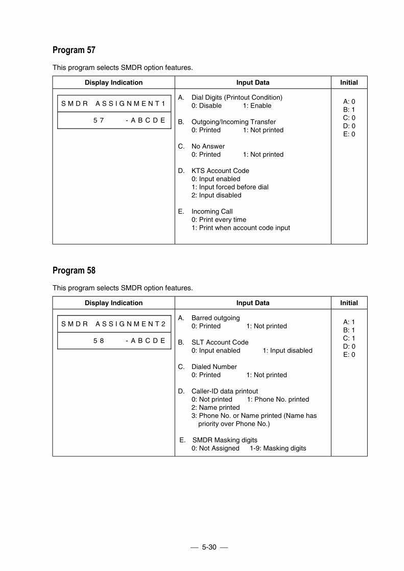
5-30
Program 57This program selects SMDR option features.
Display Indication Input Data Initial
S M D R # A S S I G N M E N T 1
# # # # # 5 7 # # # - A B C D E
A. Dial Digits (Printout Condition)0: Disable 1: Enable
B. Outgoing/Incoming Transfer0: Printed 1: Not printed
C. No Answer0: Printed 1: Not printed
D. KTS Account Code0: Input enabled1: Input forced before dial2: Input disabled
E. Incoming Call0: Print every time1: Print when account code input
A: 0B: 1C: 0D: 0E: 0
Program 58This program selects SMDR option features.
Display Indication Input Data Initial
S M D R # A S S I G N M E N T 2
# # # # # 5 8 # # # - A B C D E
A. Barred outgoing0: Printed 1: Not printed
B. SLT Account Code0: Input enabled 1: Input disabled
C. Dialed Number0: Printed 1: Not printed
D. Caller-ID data printout0: Not printed 1: Phone No. printed2: Name printed3: Phone No. or Name printed (Name has
priority over Phone No.)
E. SMDR Masking digits0: Not Assigned 1-9: Masking digits
A: 1B: 1C: 1D: 0E: 0
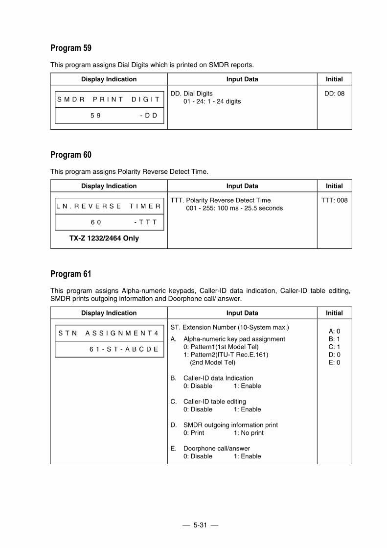
5-31
Program 59This program assigns Dial Digits which is printed on SMDR reports.
Display Indication Input Data Initial
S M D R # P R I N T # D I G I T
# # # # # 5 9 # # # # # # - D D
DD. Dial Digits01 - 24: 1 - 24 digits
DD: 08
Program 60This program assigns Polarity Reverse Detect Time.
Display Indication Input Data Initial
L N . R E V E R S E # T I M E R
# # # # # 6 0 # # # # # - T T T
TTT. Polarity Reverse Detect Time001 - 255: 100 ms - 25.5 seconds
TTT: 008
Program 61This program assigns Alpha-numeric keypads, Caller-ID data indication, Caller-ID table editing,SMDR prints outgoing information and Doorphone call/ answer.
Display Indication Input Data Initial
S T N # A S S I G N M E N T 4
# # # # # 6 1 - S T - A B C D E
ST. Extension Number (10-System max.)
A. Alpha-numeric key pad assignment0: Pattern1(1st Model Tel)1: Pattern2(ITU-T Rec.E.161) (2nd Model Tel)
B. Caller-ID data Indication0: Disable 1: Enable
C. Caller-ID table editing0: Disable 1: Enable
D. SMDR outgoing information print0: Print 1: No print
E. Doorphone call/answer0: Disable 1: Enable
A: 0B: 1C: 1D: 0E: 0
TX-Z 1232/2464 Only
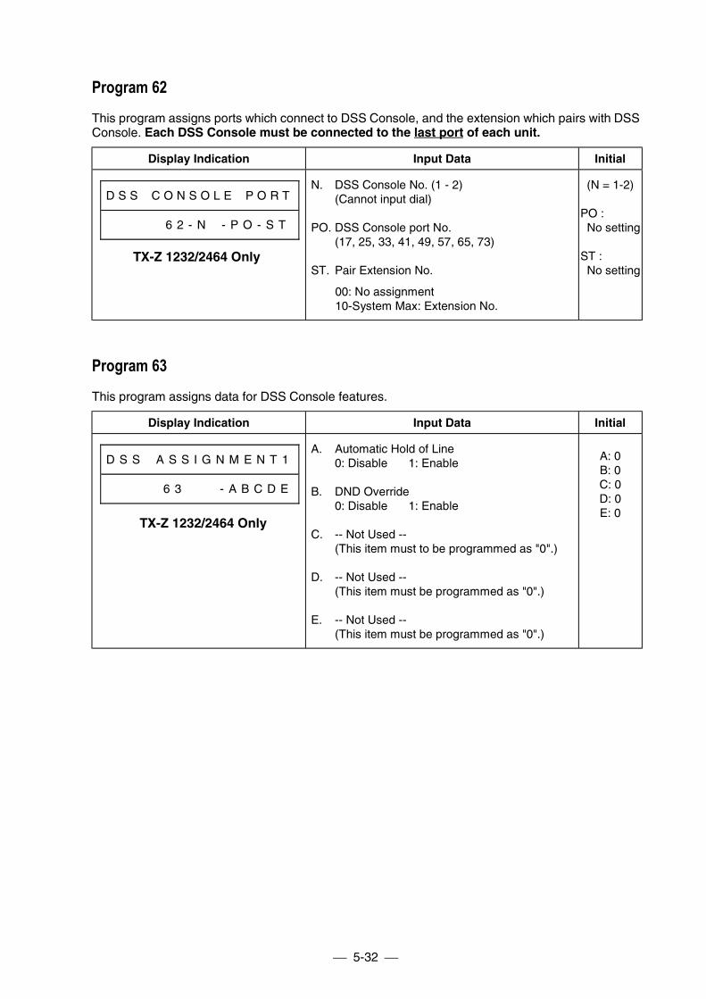
5-32
Program 62This program assigns ports which connect to DSS Console, and the extension which pairs with DSSConsole. Each DSS Console must be connected to the last port of each unit.
Display Indication Input Data Initial
D S S # C O N S O L E # P O R T
# # # # # 6 2 - N # - P O - S T
N. DSS Console No. (1 - 2)(Cannot input dial)
PO. DSS Console port No.(17, 25, 33, 41, 49, 57, 65, 73)
ST. Pair Extension No.
00: No assignment10-System Max: Extension No.
(N = 1-2)
PO :No setting
ST :No setting
Program 63This program assigns data for DSS Console features.
Display Indication Input Data Initial
D S S # A S S I G N M E N T 1
# # # # # 6 3 # # # - A B C D E
A. Automatic Hold of Line0: Disable 1: Enable
B. DND Override0: Disable 1: Enable
C. -- Not Used --(This item must to be programmed as "0".)
D. -- Not Used --(This item must be programmed as "0".)
E. -- Not Used --(This item must be programmed as "0".)
A: 0B: 0C: 0D: 0E: 0
TX-Z 1232/2464 Only
TX-Z 1232/2464 Only
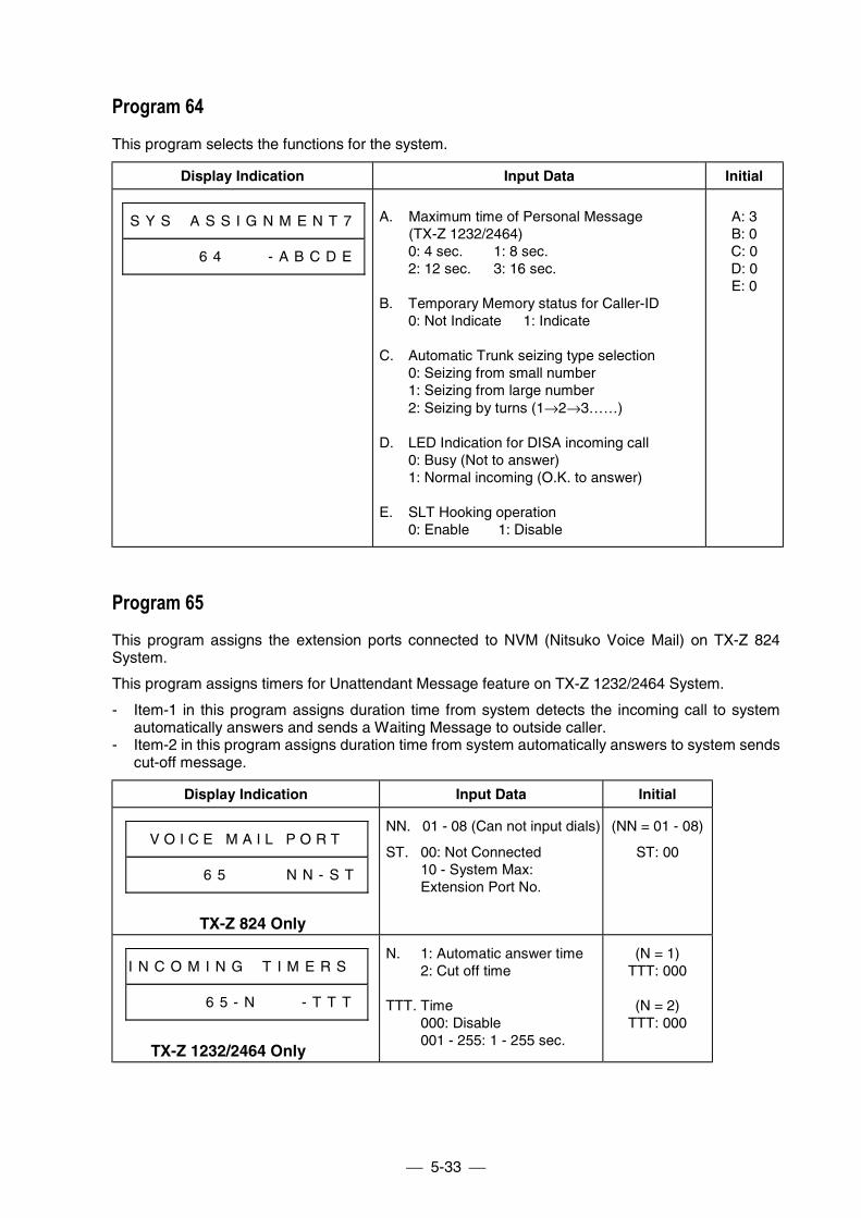
5-33
Program 64This program selects the functions for the system.
Display Indication Input Data Initial
S Y S # A S S I G N M E N T 7
# # # # # 6 4 # # # - A B C D E
A. Maximum time of Personal Message(TX-Z 1232/2464)0: 4 sec. 1: 8 sec.2: 12 sec. 3: 16 sec.
B. Temporary Memory status for Caller-ID0: Not Indicate 1: Indicate
C. Automatic Trunk seizing type selection0: Seizing from small number1: Seizing from large number2: Seizing by turns (1→2→3……)
D. LED Indication for DISA incoming call0: Busy (Not to answer)1: Normal incoming (O.K. to answer)
E. SLT Hooking operation0: Enable 1: Disable
A: 3B: 0C: 0D: 0E: 0
Program 65This program assigns the extension ports connected to NVM (Nitsuko Voice Mail) on TX-Z 824System.
This program assigns timers for Unattendant Message feature on TX-Z 1232/2464 System.
- Item-1 in this program assigns duration time from system detects the incoming call to systemautomatically answers and sends a Waiting Message to outside caller.
- Item-2 in this program assigns duration time from system automatically answers to system sendscut-off message.
Display Indication Input Data Initial
V O I C E M A I L P O R T
# # # # # 6 5 # # # # N N - S T
TX-Z 824 Only
NN. 01 - 08 (Can not input dials)
ST. 00: Not Connected10 - System Max:Extension Port No.
(NN = 01 - 08)
ST: 00
I N C O M I N G # T I M E R S #
# # # # # 6 5 - N # # # - T T T
TX-Z 1232/2464 Only
N. 1: Automatic answer time2: Cut off time
TTT. Time000: Disable001 - 255: 1 - 255 sec.
(N = 1)TTT: 000
(N = 2)TTT: 000
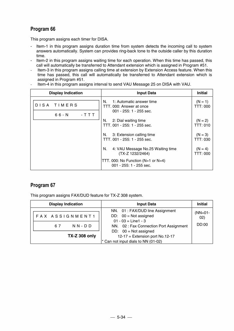
5-34
Program 66This program assigns each timer for DISA.
- Item-1 in this program assigns duration time from system detects the incoming call to systemanswers automatically. System can provides ring-back tone to the outside caller by this durationtime.
- Item-2 in this program assigns waiting time for each operation. When this time has passed, thiscall will automatically be transferred to Attendant extension which is assigned in Program #51.
- Item-3 in this program assigns calling time at extension by Extension Access feature. When thistime has passed, this call will automatically be transferred to Attendant extension which isassigned in Program #51.
- Item-4 in this program assigns interval to send VAU Message 25 on DISA with VAU.
Display Indication Input Data Initial
D I S A # T I M E R S # # # # #
# # # # # 6 6 - N # # # - T T T
N. 1: Automatic answer timeTTT. 000: Answer at once
001 - 255: 1 - 255 sec.
N. 2: Dial waiting timeTTT. 001 - 255: 1 - 255 sec.
N. 3: Extension calling timeTTT. 001 - 255: 1 - 255 sec.
N. 4: VAU Message No.25 Waiting time(TX-Z 1232/2464)
TTT. 000: No Function (N=1 or N=4) 001 - 255: 1 - 255 sec.
(N = 1)TTT: 000
(N = 2)TTT: 010
(N = 3)TTT: 030
(N = 4)TTT: 000
Program 67This program assigns FAX/DUD feature for TX-Z 308 system.
Display Indication Input Data Initial
F A X A S S I G N M E N T 1
6 7 N N - D D
NN. 01 : FAX/DUD line AssignmentDD: 00 = Not assigned
01 - 03 = Line1 - 3 NN. 02 : Fax Connection Port Assignment DD: 00 = Not assigned 12-17 = Extension port No.12-17* Can not input dials to NN (01-02)
(NN=01-02)
DD:00
TX-Z 308 only
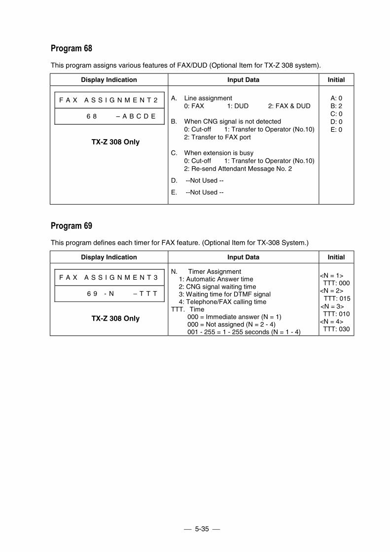
5-35
Program 68This program assigns various features of FAX/DUD (Optional Item for TX-Z 308 system).
Display Indication Input Data Initial
F A X A S S I G N M E N T 2
6 8 – A B C D E
A. Line assignment0: FAX 1: DUD 2: FAX & DUD
B. When CNG signal is not detected0: Cut-off 1: Transfer to Operator (No.10)2: Transfer to FAX port
C. When extension is busy0: Cut-off 1: Transfer to Operator (No.10)2: Re-send Attendant Message No. 2
D. --Not Used --
E. --Not Used --
A: 0B: 2C: 0D: 0E: 0
Program 69This program defines each timer for FAX feature. (Optional Item for TX-308 System.)
Display Indication Input Data Initial
F A X A S S I G N M E N T 3
# # # 6 9 - N – T T T
N. Timer Assignment 1: Automatic Answer time 2: CNG signal waiting time 3: Waiting time for DTMF signal 4: Telephone/FAX calling timeTTT. Time 000 = Immediate answer (N = 1) 000 = Not assigned (N = 2 - 4) 001 - 255 = 1 - 255 seconds (N = 1 - 4)
<N = 1> TTT: 000<N = 2> TTT: 015<N = 3> TTT: 010<N = 4> TTT: 030
TX-Z 308 Only
TX-Z 308 Only
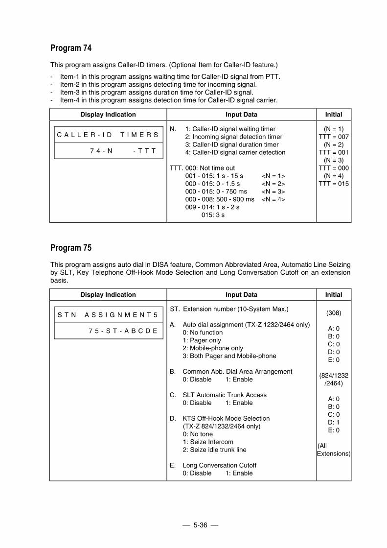
5-36
Program 74This program assigns Caller-ID timers. (Optional Item for Caller-ID feature.)
- Item-1 in this program assigns waiting time for Caller-ID signal from PTT.- Item-2 in this program assigns detecting time for incoming signal.- Item-3 in this program assigns duration time for Caller-ID signal.- Item-4 in this program assigns detection time for Caller-ID signal carrier.
Display Indication Input Data Initial
C A L L E R - I D # T I M E R S
# # # # # 7 4 - N # # # - T T T
N. 1: Caller-ID signal waiting timer2: Incoming signal detection timer3: Caller-ID signal duration timer4: Caller-ID signal carrier detection
TTT. 000: Not time out001 - 015: 1 s - 15 s <N = 1>000 - 015: 0 - 1.5 s <N = 2>000 - 015: 0 - 750 ms <N = 3>000 - 008: 500 - 900 ms <N = 4>009 - 014: 1 s - 2 s 015: 3 s
(N = 1)TTT = 007
(N = 2)TTT = 001
(N = 3)TTT = 000
(N = 4)TTT = 015
Program 75This program assigns auto dial in DISA feature, Common Abbreviated Area, Automatic Line Seizingby SLT, Key Telephone Off-Hook Mode Selection and Long Conversation Cutoff on an extensionbasis.
Display Indication Input Data Initial
S T N # A S S I G N M E N T 5
# # # # # 7 5 - S T - A B C D E
ST. Extension number (10-System Max.)
A. Auto dial assignment (TX-Z 1232/2464 only)0: No function1: Pager only2: Mobile-phone only3: Both Pager and Mobile-phone
B. Common Abb. Dial Area Arrangement0: Disable 1: Enable
C. SLT Automatic Trunk Access0: Disable 1: Enable
D. KTS Off-Hook Mode Selection(TX-Z 824/1232/2464 only)0: No tone1: Seize Intercom2: Seize idle trunk line
E. Long Conversation Cutoff0: Disable 1: Enable
(308)
A: 0B: 0C: 0D: 0E: 0
(824/1232/2464)
A: 0B: 0C: 0D: 1E: 0
(AllExtensions)
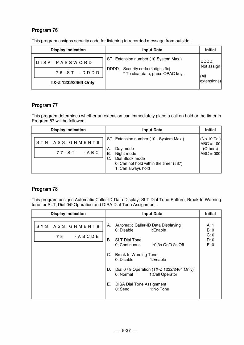
5-37
Program 76This program assigns security code for listening to recorded message from outside.
Display Indication Input Data Initial
D I S A # P A S S W O R D # #
# # # # # 7 6 - S T # - D D D D
ST. Extension number (10-System Max.)
DDDD. Security code (4 digits fix)* To clear data, press OPAC key.
DDDD:Not assign
(Allextensions)
Program 77This program determines whether an extension can immediately place a call on hold or the timer inProgram 87 will be followed.
Display Indication Input Data Initial
S T N # A S S I G N M E N T 6
# # # # # 7 7 - S T # # - A B C
ST. Extension number (10 - System Max.)
A. Day modeB. Night modeC. Dial Block mode
0: Can not hold within the timer (#87)1: Can always hold
(No.10 Tel)ABC = 100
(Others)ABC = 000
Program 78This program assigns Automatic Caller-ID Data Display, SLT Dial Tone Pattern, Break-In Warningtone for SLT, Dial 0/9 Operation and DISA Dial Tone Assignment.
Display Indication Input Data Initial
S Y S # A S S I G N M E N T 8
# # # # # 7 8 - A B C D E
A. Automatic Caller-ID Data Displaying0: Disable 1:Enable
B. SLT Dial Tone0: Continuous 1:0.3s On/0.2s Off
C. Break In Warning Tone0: Disable 1:Enable
D. Dial 0 / 9 Operation (TX-Z 1232/2464 Only)0: Normal 1:Call Operator
E. DISA Dial Tone Assignment0: Send 1:No Tone
A: 1B: 0C: 0D: 0E: 0
TX-Z 1232/2464 Only
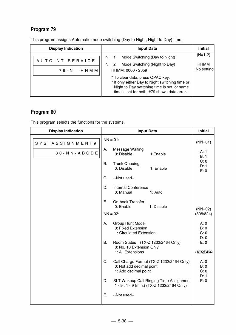
5-38
Program 79This program assigns Automatic mode switching (Day to Night, Night to Day) time.
Display Indication Input Data Initial
A U T O N T S E R V I C E
# # # # # 7 9 - N – H H M M
N. 1 Mode Switching (Day to Night)
N. 2 Mode Switching (Night to Day)
HHMM: 0000 - 2359
* To clear data, press OPAC key.* If only either Day to Night switching time or
Night to Day switching time is set, or sametime is set for both, #79 shows data error.
(N=1-2)
HHMM: No setting
Program 80This program selects the functions for the systems.
Display Indication Input Data Initial
S Y S # A S S I G N M E N T 9
# # # # 8 0 - N N - A B C D E
NN = 01:
A. Message Waiting0: Disable 1:Enable
B. Trunk Queuing0: Disable 1: Enable
C. --Not used--
D. Internal Conference0: Manual 1: Auto
E. On-hook Transfer0: Enable 1: Disable
NN = 02:
A. Group Hunt Mode0: Fixed Extension1: Circulated Extension
B. Room Status (TX-Z 1232/2464 Only)0: No. 10 Extension Only1: All Extensions
C. Call Charge Format (TX-Z 1232/2464 Only)0: Not add decimal point1: Add decimal point
D. SLT Wakeup Call Ringing Time Assignment1 - 9 : 1 - 9 (min.) (TX-Z 1232/2464 Only)
E. --Not used--
(NN=01)
A: 1B: 1C: 0D: 1E: 0
(NN=02)(308/824)
A: 0B: 0C: 0D: 0E: 0
(1232/2464)
A: 0B: 0C: 0D: 1E: 0
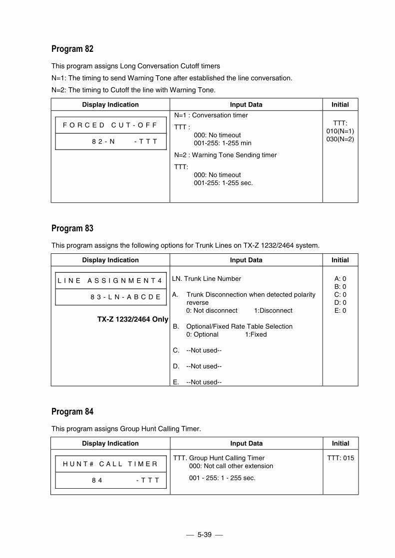
5-39
Program 82This program assigns Long Conversation Cutoff timers
N=1: The timing to send Warning Tone after established the line conversation.
N=2: The timing to Cutoff the line with Warning Tone.
Display Indication Input Data Initial
F O R C E D C U T - O F F
# # # 8 8 2 - N - T T T
N=1 : Conversation timer
TTT :000: No timeout001-255: 1-255 min
N=2 : Warning Tone Sending timer
TTT:000: No timeout001-255: 1-255 sec.
TTT:010(N=1)030(N=2)
Program 83This program assigns the following options for Trunk Lines on TX-Z 1232/2464 system.
Display Indication Input Data Initial
L I N E A S S I G N M E N T 4
# # # # # 8 3 - L N - A B C D E
TX-Z 1232/2464 Only
LN. Trunk Line Number
A. Trunk Disconnection when detected polarityreverse
0: Not disconnect 1:Disconnect
B. Optional/Fixed Rate Table Selection0: Optional 1:Fixed
C. --Not used--
D. --Not used--
E. --Not used--
A: 0B: 0C: 0D: 0E: 0
Program 84This program assigns Group Hunt Calling Timer.
Display Indication Input Data Initial
H U N T # C A L L T I M E R
# # # # # 8 4 # # # # # - T T T
TTT. Group Hunt Calling Timer000: Not call other extension
001 - 255: 1 - 255 sec.
TTT: 015
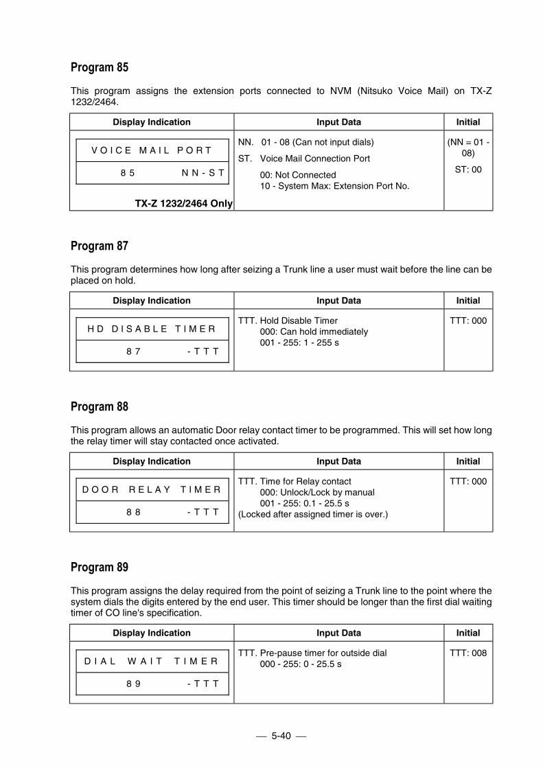
5-40
Program 85This program assigns the extension ports connected to NVM (Nitsuko Voice Mail) on TX-Z1232/2464.
Display Indication Input Data Initial
V O I C E M A I L P O R T
# # # # # 8 5 # # # # # N N - S T
TX-Z 1232/2464 Only
NN. 01 - 08 (Can not input dials)
ST. Voice Mail Connection Port
00: Not Connected10 - System Max: Extension Port No.
(NN = 01 -08)
ST: 00
Program 87This program determines how long after seizing a Trunk line a user must wait before the line can beplaced on hold.
Display Indication Input Data Initial
H D D I S A B L E T I M E R
# # # # # 8 7 # # # # # - T T T
TTT. Hold Disable Timer000: Can hold immediately001 - 255: 1 - 255 s
TTT: 000
Program 88This program allows an automatic Door relay contact timer to be programmed. This will set how longthe relay timer will stay contacted once activated.
Display Indication Input Data Initial
D O O R # R E L A Y # T I M E R
# # # # # 8 8 # # # # # - T T T
TTT. Time for Relay contact000: Unlock/Lock by manual001 - 255: 0.1 - 25.5 s
(Locked after assigned timer is over.)
TTT: 000
Program 89This program assigns the delay required from the point of seizing a Trunk line to the point where thesystem dials the digits entered by the end user. This timer should be longer than the first dial waitingtimer of CO line's specification.
Display Indication Input Data Initial
D I A L # W A I T # T I M E R
# # # # # 8 9 # # # # # - T T T
TTT. Pre-pause timer for outside dial000 - 255: 0 - 25.5 s
TTT: 008
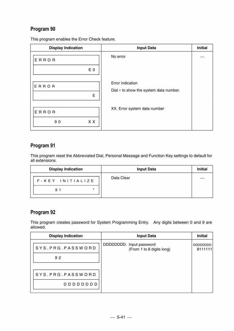
5-41
Program 90This program enables the Error Check feature.
Display Indication Input Data Initial
E R R O R # # # # # # # # # # #
# # # # # # # # # # # # # # E 0
No error
E R R O R # # # # # # # # # # #
# # # # # # # # # # # # # # # E
Error indication
Dial ∗ to show the system data number.
E R R O R # # # # # # # # # # #
# # # # # 9 0 # # # # # # # X X
XX. Error system data number
Program 91This program reset the Abbreviated Dial, Personal Message and Function Key settings to default forall extensions.
Display Indication Input Data Initial
F - K E Y # I N I T I A L I Z E
# # # # # 9 1 # # # # # # # # *
Data Clear
Program 92This program creates password for System Programming Entry. Any digits between 0 and 9 areallowed.
Display Indication Input Data Initial
S Y S . P R G . P A S S W O R D
# # # # # 9 2 # # # # # # # # #
S Y S . P R G . P A S S W O R D
# # # # # # # # D D D D D D D D
DDDDDDDD. Input password(From 1 to 8 digits long)
DDDDDDDD:
8111111
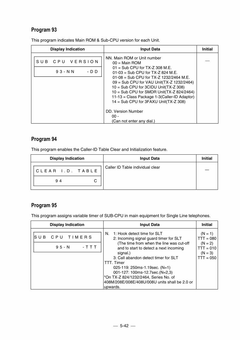
5-42
Program 93This program indicates Main ROM & Sub-CPU version for each Unit.
Display Indication Input Data Initial
S U B # C P U # V E R S I O N
# # # # # 9 3 - N N # # # - D D
NN. Main ROM or Unit number 00 = Main ROM
01 = Sub CPU for TX-Z 308 M.E.01-03 = Sub CPU for TX-Z 824 M.E.
01-08 = Sub CPU for TX-Z 1232/2464 M.E. 09 = Sub CPU for VAU Unit(TX-Z 1232/2464) 10 = Sub CPU for 3CIDU Unit(TX-Z 308) 10 = Sub CPU for SMDR Unit(TX-Z 824/2464) 11-13 = Class Package 1-3(Caller-ID Adaptor) 14 = Sub CPU for 3FAXU Unit(TX-Z 308)
DD. Version Number 00 - (Can not enter any dial.)
Program 94This program enables the Caller-ID Table Clear and Initialization feature.
Display Indication Input Data Initial
C L E A R # I . D . # T A B L E
# # # # # 9 4 # # # # # # # # C
Caller ID Table individual clear—
Program 95This program assigns variable timer of SUB-CPU in main equipment for Single Line telephones.
Display Indication Input Data Initial
S U B # C P U # T I M E R S # #
# # # # # 9 5 - N # # # - T T T
N. 1: Hook detect time for SLT2: Incoming signal guard timer for SLT
(The time from when the line was cut-offand to start to detect a next incomingsignal.)
3: Call abandon detect timer for SLTTTT. Timer
025-119: 250ms-1.19sec. (N=1)001-127: 100ms-12.7sec.(N=2,3)
*On TX-Z 824/1232/2464, Series No. of408M/208E/008E/408U/008U units shall be 2.0 orupwards.
(N = 1)TTT = 080
(N = 2)TTT = 010
(N = 3)TTT = 050
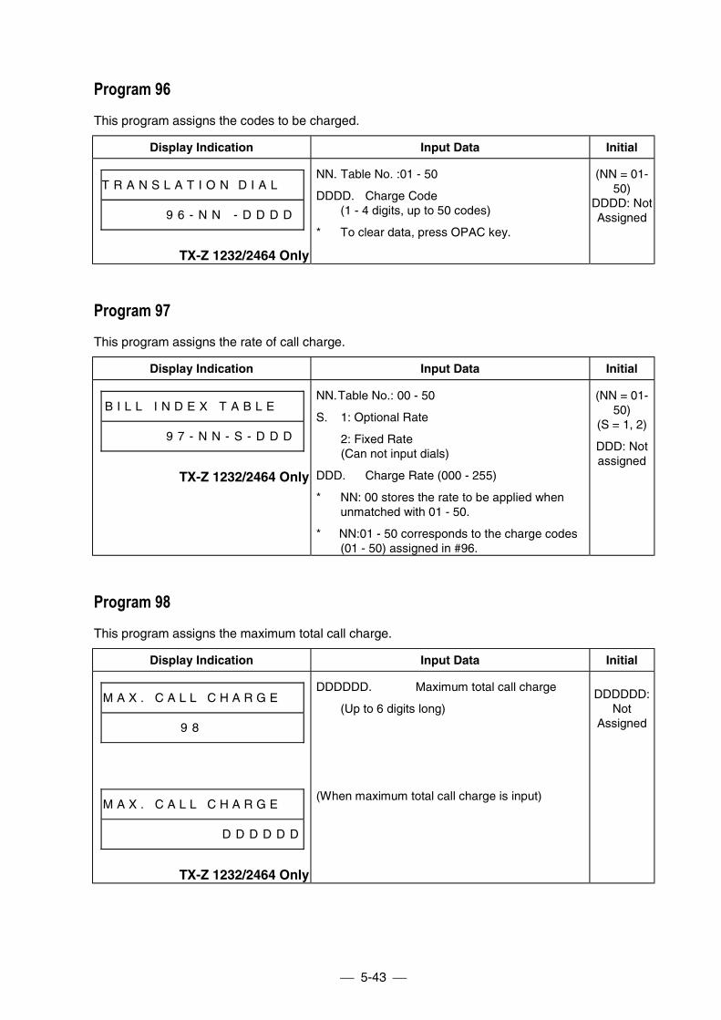
5-43
Program 96This program assigns the codes to be charged.
Display Indication Input Data Initial
T R A N S L A T I O N D I A L # #
# # # # # 9 6 - N N - D D D D
TX-Z 1232/2464 Only
NN. Table No. :01 - 50
DDDD. Charge Code(1 - 4 digits, up to 50 codes)
* To clear data, press OPAC key.
(NN = 01-50)
DDDD: NotAssigned
Program 97This program assigns the rate of call charge.
Display Indication Input Data Initial
B I L L I N D E X T A B L E # #
# # # # # 9 7 - N N - S - D D D
TX-Z 1232/2464 Only
NN. Table No.: 00 - 50
S. 1: Optional Rate
2: Fixed Rate(Can not input dials)
DDD. Charge Rate (000 - 255)
* NN: 00 stores the rate to be applied whenunmatched with 01 - 50.
* NN:01 - 50 corresponds to the charge codes(01 - 50) assigned in #96.
(NN = 01-50)
(S = 1, 2)
DDD: Notassigned
Program 98This program assigns the maximum total call charge.
Display Indication Input Data Initial
M A X . C A L L C H A R G E # #
9 8
M A X . C A L L C H A R G E # #
D D D D D D
TX-Z 1232/2464 Only
DDDDDD. Maximum total call charge
(Up to 6 digits long)
(When maximum total call charge is input)
DDDDDD:Not
Assigned
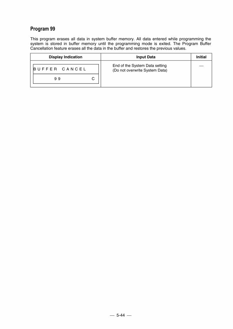
5-44
Program 99This program erases all data in system buffer memory. All data entered while programming thesystem is stored in buffer memory until the programming mode is exited. The Program BufferCancellation feature erases all the data in the buffer and restores the previous values.
Display Indication Input Data Initial
B U F F E R # C A N C E L # # #
# # # # # 9 9 # # # # # # # # C
End of the System Data setting(Do not overwrite System Data)
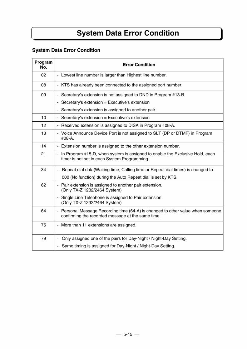
5-45
System Data Error Condition
System Data Error Condition
ProgramNo. Error Condition
02 - Lowest line number is larger than Highest line number.
08 - KTS has already been connected to the assigned port number.
09 - Secretary's extension is not assigned to DND in Program #13-B.
- Secretary's extension = Executive's extension
- Secretary's extension is assigned to another pair.
10 - Secretary's extension = Executive's extension
12 - Received extension is assigned to DISA in Program #08-A.
13 - Voice Announce Device Port is not assigned to SLT (DP or DTMF) in Program#08-A.
14 - Extension number is assigned to the other extension number.
21 - In Program #15-D, when system is assigned to enable the Exclusive Hold, eachtimer is not set in each System Programming.
34 - Repeat dial data(Waiting time, Calling time or Repeat dial times) is changed to
000 (No function) during the Auto Repeat dial is set by KTS.
62 - Pair extension is assigned to another pair extension.(Only TX-Z 1232/2464 System)
- Single Line Telephone is assigned to Pair extension.(Only TX-Z 1232/2464 System)
64 - Personal Message Recording time (64-A) is changed to other value when someoneconfirming the recorded message at the same time.
75 - More than 11 extensions are assigned.
79 - Only assigned one of the pairs for Day-Night / Night-Day Setting.
- Same timing is assigned for Day-Night / Night-Day Setting.
PART 6
PROGRAM RECORD FORM
Line Assignment
Extension Assignment
Other Assignment
Restrict Code Assignment
Security Code Assignment
Each Option Assignment
System Assignment
Each Timer Assignment
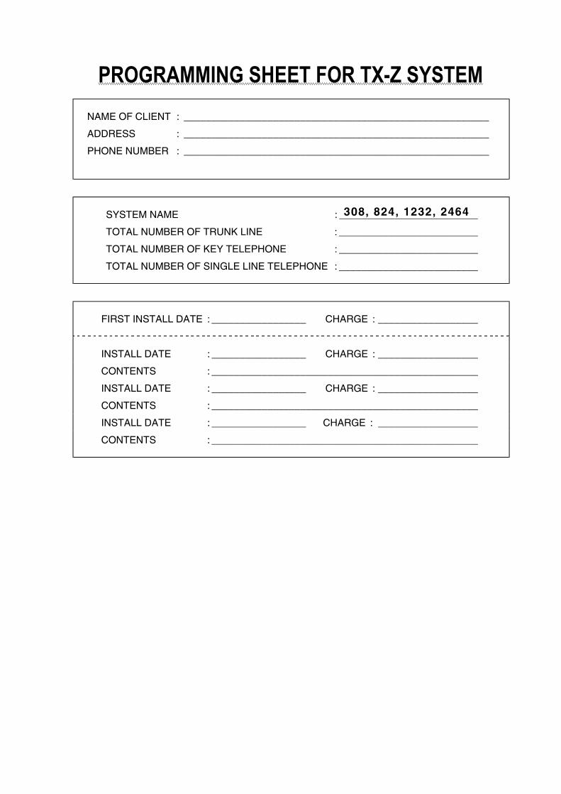
PROGRAMMING SHEET FOR TX-Z SYSTEMNAME OF CLIENT : _______________________________________________________
ADDRESS : _______________________________________________________
PHONE NUMBER : _______________________________________________________
SYSTEM NAME : _________________________
TOTAL NUMBER OF TRUNK LINE : _________________________
TOTAL NUMBER OF KEY TELEPHONE : _________________________
TOTAL NUMBER OF SINGLE LINE TELEPHONE : _________________________
FIRST INSTALL DATE : _________________ CHARGE : __________________
INSTALL DATE : _________________ CHARGE : __________________
CONTENTS : ________________________________________________
INSTALL DATE : _________________ CHARGE : __________________
CONTENTS : ________________________________________________
INSTALL DATE : _________________ CHARGE : __________________
CONTENTS : ________________________________________________
308, 824, 1232, 2464
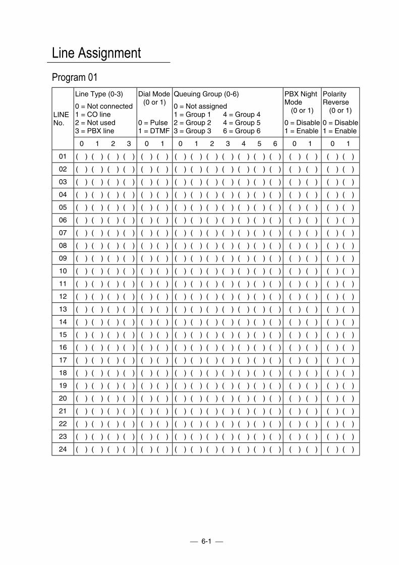
6-1
Line AssignmentProgram 01
Line Type (0-3)
0 = Not connected1 = CO line2 = Not used3 = PBX line
Dial Mode(0 or 1)
0 = Pulse1 = DTMF
Queuing Group (0-6)
0 = Not assigned1 = Group 1 4 = Group 42 = Group 2 4 = Group 53 = Group 3 6 = Group 6
PBX NightMode
(0 or 1)
0 = Disable1 = Enable
PolarityReverse
(0 or 1)
0 = Disable1 = Enable
LINENo.
0 1 2 3 0 1 0 1 2 3 4 5 6 0 1 0 1
01 ( ) ( ) ( ) ( ) ( ) ( ) ( ) ( ) ( ) ( ) ( ) ( ) ( ) ( ) ( ) ( ) ( )
02 ( ) ( ) ( ) ( ) ( ) ( ) ( ) ( ) ( ) ( ) ( ) ( ) ( ) ( ) ( ) ( ) ( )
03 ( ) ( ) ( ) ( ) ( ) ( ) ( ) ( ) ( ) ( ) ( ) ( ) ( ) ( ) ( ) ( ) ( )
04 ( ) ( ) ( ) ( ) ( ) ( ) ( ) ( ) ( ) ( ) ( ) ( ) ( ) ( ) ( ) ( ) ( )
05 ( ) ( ) ( ) ( ) ( ) ( ) ( ) ( ) ( ) ( ) ( ) ( ) ( ) ( ) ( ) ( ) ( )
06 ( ) ( ) ( ) ( ) ( ) ( ) ( ) ( ) ( ) ( ) ( ) ( ) ( ) ( ) ( ) ( ) ( )
07 ( ) ( ) ( ) ( ) ( ) ( ) ( ) ( ) ( ) ( ) ( ) ( ) ( ) ( ) ( ) ( ) ( )
08 ( ) ( ) ( ) ( ) ( ) ( ) ( ) ( ) ( ) ( ) ( ) ( ) ( ) ( ) ( ) ( ) ( )
09 ( ) ( ) ( ) ( ) ( ) ( ) ( ) ( ) ( ) ( ) ( ) ( ) ( ) ( ) ( ) ( ) ( )
10 ( ) ( ) ( ) ( ) ( ) ( ) ( ) ( ) ( ) ( ) ( ) ( ) ( ) ( ) ( ) ( ) ( )
11 ( ) ( ) ( ) ( ) ( ) ( ) ( ) ( ) ( ) ( ) ( ) ( ) ( ) ( ) ( ) ( ) ( )
12 ( ) ( ) ( ) ( ) ( ) ( ) ( ) ( ) ( ) ( ) ( ) ( ) ( ) ( ) ( ) ( ) ( )
13 ( ) ( ) ( ) ( ) ( ) ( ) ( ) ( ) ( ) ( ) ( ) ( ) ( ) ( ) ( ) ( ) ( )
14 ( ) ( ) ( ) ( ) ( ) ( ) ( ) ( ) ( ) ( ) ( ) ( ) ( ) ( ) ( ) ( ) ( )
15 ( ) ( ) ( ) ( ) ( ) ( ) ( ) ( ) ( ) ( ) ( ) ( ) ( ) ( ) ( ) ( ) ( )
16 ( ) ( ) ( ) ( ) ( ) ( ) ( ) ( ) ( ) ( ) ( ) ( ) ( ) ( ) ( ) ( ) ( )
17 ( ) ( ) ( ) ( ) ( ) ( ) ( ) ( ) ( ) ( ) ( ) ( ) ( ) ( ) ( ) ( ) ( )
18 ( ) ( ) ( ) ( ) ( ) ( ) ( ) ( ) ( ) ( ) ( ) ( ) ( ) ( ) ( ) ( ) ( )
19 ( ) ( ) ( ) ( ) ( ) ( ) ( ) ( ) ( ) ( ) ( ) ( ) ( ) ( ) ( ) ( ) ( )
20 ( ) ( ) ( ) ( ) ( ) ( ) ( ) ( ) ( ) ( ) ( ) ( ) ( ) ( ) ( ) ( ) ( )
21 ( ) ( ) ( ) ( ) ( ) ( ) ( ) ( ) ( ) ( ) ( ) ( ) ( ) ( ) ( ) ( ) ( )
22 ( ) ( ) ( ) ( ) ( ) ( ) ( ) ( ) ( ) ( ) ( ) ( ) ( ) ( ) ( ) ( ) ( )
23 ( ) ( ) ( ) ( ) ( ) ( ) ( ) ( ) ( ) ( ) ( ) ( ) ( ) ( ) ( ) ( ) ( )
24 ( ) ( ) ( ) ( ) ( ) ( ) ( ) ( ) ( ) ( ) ( ) ( ) ( ) ( ) ( ) ( ) ( )
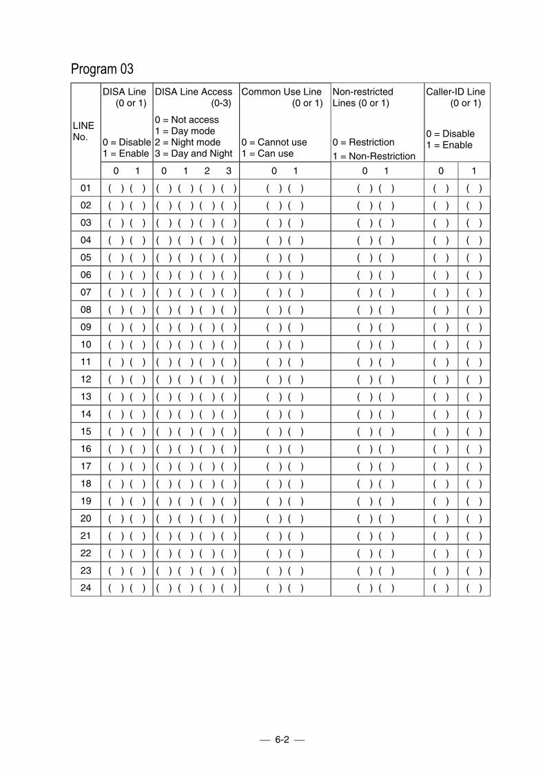
6-2
Program 03DISA Line
(0 or 1)
0 = Disable1 = Enable
DISA Line Access(0-3)
0 = Not access1 = Day mode2 = Night mode3 = Day and Night
Common Use Line(0 or 1)
0 = Cannot use1 = Can use
Non-restrictedLines (0 or 1)
0 = Restriction1 = Non-Restriction
Caller-ID Line (0 or 1)
0 = Disable1 = Enable
LINENo.
0 1 0 1 2 3 0 1 0 1 0 1
01 ( ) ( ) ( ) ( ) ( ) ( ) ( ) ( ) ( ) ( ) ( ) ( )
02 ( ) ( ) ( ) ( ) ( ) ( ) ( ) ( ) ( ) ( ) ( ) ( )
03 ( ) ( ) ( ) ( ) ( ) ( ) ( ) ( ) ( ) ( ) ( ) ( )
04 ( ) ( ) ( ) ( ) ( ) ( ) ( ) ( ) ( ) ( ) ( ) ( )
05 ( ) ( ) ( ) ( ) ( ) ( ) ( ) ( ) ( ) ( ) ( ) ( )
06 ( ) ( ) ( ) ( ) ( ) ( ) ( ) ( ) ( ) ( ) ( ) ( )
07 ( ) ( ) ( ) ( ) ( ) ( ) ( ) ( ) ( ) ( ) ( ) ( )
08 ( ) ( ) ( ) ( ) ( ) ( ) ( ) ( ) ( ) ( ) ( ) ( )
09 ( ) ( ) ( ) ( ) ( ) ( ) ( ) ( ) ( ) ( ) ( ) ( )
10 ( ) ( ) ( ) ( ) ( ) ( ) ( ) ( ) ( ) ( ) ( ) ( )
11 ( ) ( ) ( ) ( ) ( ) ( ) ( ) ( ) ( ) ( ) ( ) ( )
12 ( ) ( ) ( ) ( ) ( ) ( ) ( ) ( ) ( ) ( ) ( ) ( )
13 ( ) ( ) ( ) ( ) ( ) ( ) ( ) ( ) ( ) ( ) ( ) ( )
14 ( ) ( ) ( ) ( ) ( ) ( ) ( ) ( ) ( ) ( ) ( ) ( )
15 ( ) ( ) ( ) ( ) ( ) ( ) ( ) ( ) ( ) ( ) ( ) ( )
16 ( ) ( ) ( ) ( ) ( ) ( ) ( ) ( ) ( ) ( ) ( ) ( )
17 ( ) ( ) ( ) ( ) ( ) ( ) ( ) ( ) ( ) ( ) ( ) ( )
18 ( ) ( ) ( ) ( ) ( ) ( ) ( ) ( ) ( ) ( ) ( ) ( )
19 ( ) ( ) ( ) ( ) ( ) ( ) ( ) ( ) ( ) ( ) ( ) ( )
20 ( ) ( ) ( ) ( ) ( ) ( ) ( ) ( ) ( ) ( ) ( ) ( )
21 ( ) ( ) ( ) ( ) ( ) ( ) ( ) ( ) ( ) ( ) ( ) ( )
22 ( ) ( ) ( ) ( ) ( ) ( ) ( ) ( ) ( ) ( ) ( ) ( )
23 ( ) ( ) ( ) ( ) ( ) ( ) ( ) ( ) ( ) ( ) ( ) ( )
24 ( ) ( ) ( ) ( ) ( ) ( ) ( ) ( ) ( ) ( ) ( ) ( )
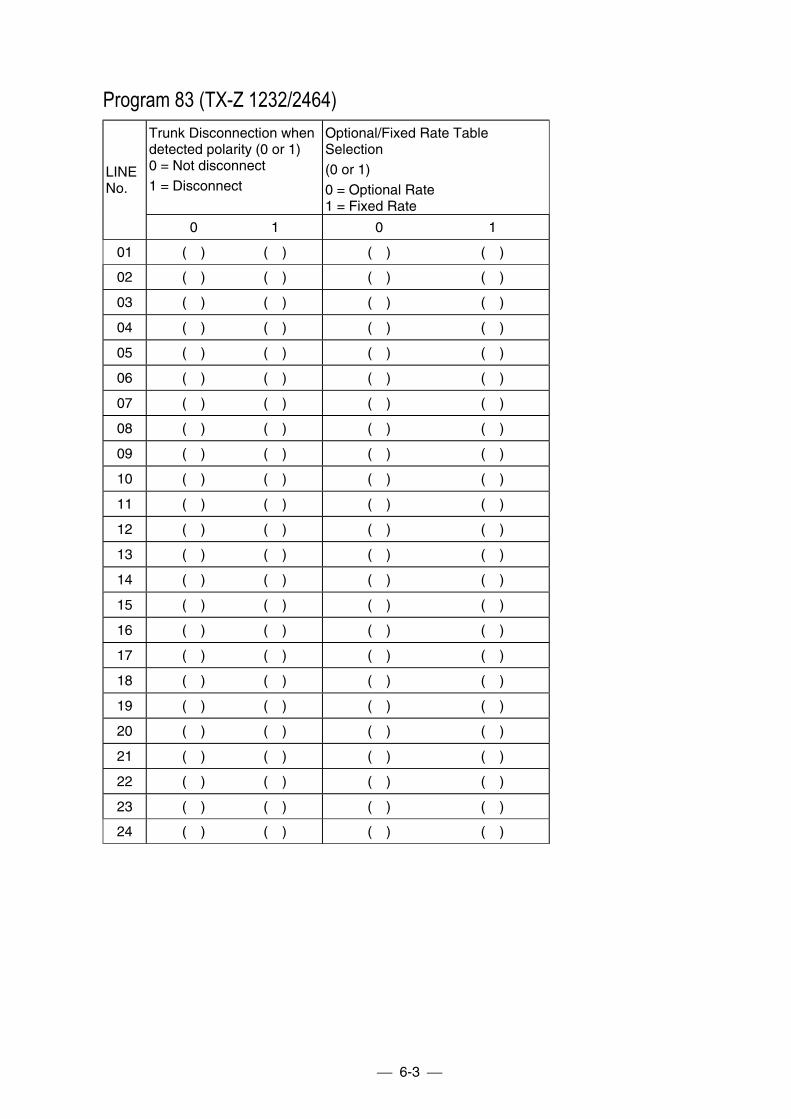
6-3
Program 83 (TX-Z 1232/2464)Trunk Disconnection whendetected polarity (0 or 1)0 = Not disconnect1 = Disconnect
Optional/Fixed Rate TableSelection(0 or 1)0 = Optional Rate1 = Fixed Rate
LINENo.
0 1 0 1
01 ( ) ( ) ( ) ( )
02 ( ) ( ) ( ) ( )
03 ( ) ( ) ( ) ( )
04 ( ) ( ) ( ) ( )
05 ( ) ( ) ( ) ( )
06 ( ) ( ) ( ) ( )
07 ( ) ( ) ( ) ( )
08 ( ) ( ) ( ) ( )
09 ( ) ( ) ( ) ( )
10 ( ) ( ) ( ) ( )
11 ( ) ( ) ( ) ( )
12 ( ) ( ) ( ) ( )
13 ( ) ( ) ( ) ( )
14 ( ) ( ) ( ) ( )
15 ( ) ( ) ( ) ( )
16 ( ) ( ) ( ) ( )
17 ( ) ( ) ( ) ( )
18 ( ) ( ) ( ) ( )
19 ( ) ( ) ( ) ( )
20 ( ) ( ) ( ) ( )
21 ( ) ( ) ( ) ( )
22 ( ) ( ) ( ) ( )
23 ( ) ( ) ( ) ( )
24 ( ) ( ) ( ) ( )
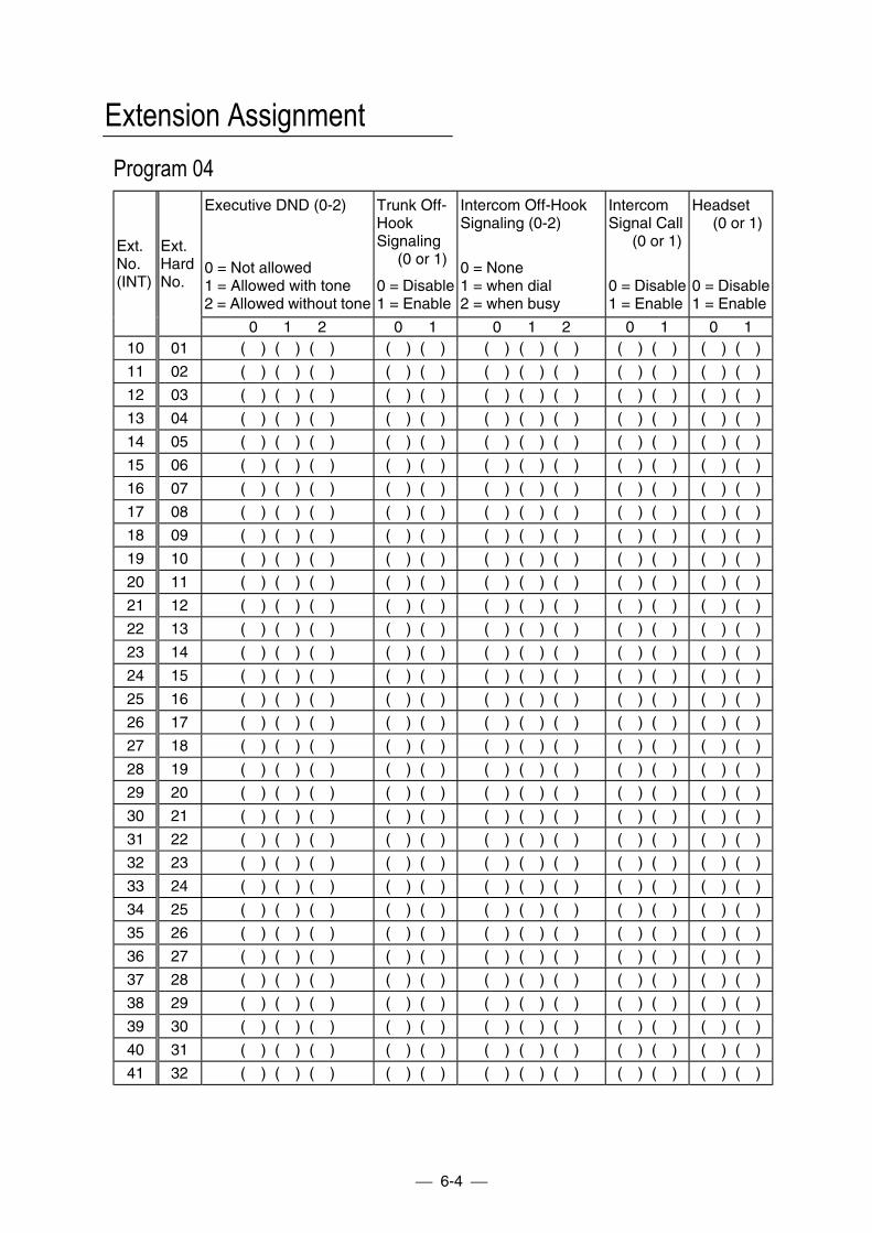
6-4
Extension AssignmentProgram 04
Executive DND (0-2)
0 = Not allowed1 = Allowed with tone2 = Allowed without tone
Trunk Off-HookSignaling
(0 or 1)
0 = Disable1 = Enable
Intercom Off-HookSignaling (0-2)
0 = None1 = when dial2 = when busy
IntercomSignal Call
(0 or 1)
0 = Disable1 = Enable
Headset(0 or 1)
0 = Disable1 = Enable
Ext.No.(INT)
Ext.HardNo.
0 1 2 0 1 0 1 2 0 1 0 110 01 ( ) ( ) ( ) ( ) ( ) ( ) ( ) ( ) ( ) ( ) ( ) ( )
11 02 ( ) ( ) ( ) ( ) ( ) ( ) ( ) ( ) ( ) ( ) ( ) ( )
12 03 ( ) ( ) ( ) ( ) ( ) ( ) ( ) ( ) ( ) ( ) ( ) ( )
13 04 ( ) ( ) ( ) ( ) ( ) ( ) ( ) ( ) ( ) ( ) ( ) ( )
14 05 ( ) ( ) ( ) ( ) ( ) ( ) ( ) ( ) ( ) ( ) ( ) ( )
15 06 ( ) ( ) ( ) ( ) ( ) ( ) ( ) ( ) ( ) ( ) ( ) ( )
16 07 ( ) ( ) ( ) ( ) ( ) ( ) ( ) ( ) ( ) ( ) ( ) ( )
17 08 ( ) ( ) ( ) ( ) ( ) ( ) ( ) ( ) ( ) ( ) ( ) ( )
18 09 ( ) ( ) ( ) ( ) ( ) ( ) ( ) ( ) ( ) ( ) ( ) ( )
19 10 ( ) ( ) ( ) ( ) ( ) ( ) ( ) ( ) ( ) ( ) ( ) ( )
20 11 ( ) ( ) ( ) ( ) ( ) ( ) ( ) ( ) ( ) ( ) ( ) ( )
21 12 ( ) ( ) ( ) ( ) ( ) ( ) ( ) ( ) ( ) ( ) ( ) ( )
22 13 ( ) ( ) ( ) ( ) ( ) ( ) ( ) ( ) ( ) ( ) ( ) ( )
23 14 ( ) ( ) ( ) ( ) ( ) ( ) ( ) ( ) ( ) ( ) ( ) ( )
24 15 ( ) ( ) ( ) ( ) ( ) ( ) ( ) ( ) ( ) ( ) ( ) ( )
25 16 ( ) ( ) ( ) ( ) ( ) ( ) ( ) ( ) ( ) ( ) ( ) ( )
26 17 ( ) ( ) ( ) ( ) ( ) ( ) ( ) ( ) ( ) ( ) ( ) ( )
27 18 ( ) ( ) ( ) ( ) ( ) ( ) ( ) ( ) ( ) ( ) ( ) ( )
28 19 ( ) ( ) ( ) ( ) ( ) ( ) ( ) ( ) ( ) ( ) ( ) ( )
29 20 ( ) ( ) ( ) ( ) ( ) ( ) ( ) ( ) ( ) ( ) ( ) ( )
30 21 ( ) ( ) ( ) ( ) ( ) ( ) ( ) ( ) ( ) ( ) ( ) ( )
31 22 ( ) ( ) ( ) ( ) ( ) ( ) ( ) ( ) ( ) ( ) ( ) ( )
32 23 ( ) ( ) ( ) ( ) ( ) ( ) ( ) ( ) ( ) ( ) ( ) ( )
33 24 ( ) ( ) ( ) ( ) ( ) ( ) ( ) ( ) ( ) ( ) ( ) ( )
34 25 ( ) ( ) ( ) ( ) ( ) ( ) ( ) ( ) ( ) ( ) ( ) ( )
35 26 ( ) ( ) ( ) ( ) ( ) ( ) ( ) ( ) ( ) ( ) ( ) ( )
36 27 ( ) ( ) ( ) ( ) ( ) ( ) ( ) ( ) ( ) ( ) ( ) ( )
37 28 ( ) ( ) ( ) ( ) ( ) ( ) ( ) ( ) ( ) ( ) ( ) ( )
38 29 ( ) ( ) ( ) ( ) ( ) ( ) ( ) ( ) ( ) ( ) ( ) ( )
39 30 ( ) ( ) ( ) ( ) ( ) ( ) ( ) ( ) ( ) ( ) ( ) ( )
40 31 ( ) ( ) ( ) ( ) ( ) ( ) ( ) ( ) ( ) ( ) ( ) ( )
41 32 ( ) ( ) ( ) ( ) ( ) ( ) ( ) ( ) ( ) ( ) ( ) ( )
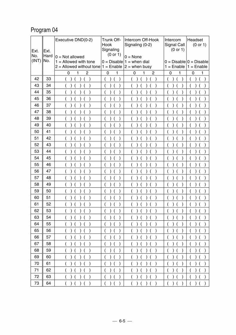
6-5
Program 04Executive DND(0-2)
0 = Not allowed1 = Allowed with tone2 = Allowed without tone
Trunk Off-HookSignaling
(0 or 1)
0 = Disable1 = Enable
Intercom Off-HookSignaling (0-2)
0 = None1 = when dial2 = when busy
IntercomSignal Call
(0 or 1)
0 = Disable1 = Enable
Headset(0 or 1)
0 = Disable1 = Enable
Ext.No.(INT)
Ext.HardNo.
0 1 2 0 1 0 1 2 0 1 0 142 33 ( ) ( ) ( ) ( ) ( ) ( ) ( ) ( ) ( ) ( ) ( ) ( )
43 34 ( ) ( ) ( ) ( ) ( ) ( ) ( ) ( ) ( ) ( ) ( ) ( )
44 35 ( ) ( ) ( ) ( ) ( ) ( ) ( ) ( ) ( ) ( ) ( ) ( )
45 36 ( ) ( ) ( ) ( ) ( ) ( ) ( ) ( ) ( ) ( ) ( ) ( )
46 37 ( ) ( ) ( ) ( ) ( ) ( ) ( ) ( ) ( ) ( ) ( ) ( )
47 38 ( ) ( ) ( ) ( ) ( ) ( ) ( ) ( ) ( ) ( ) ( ) ( )
48 39 ( ) ( ) ( ) ( ) ( ) ( ) ( ) ( ) ( ) ( ) ( ) ( )
49 40 ( ) ( ) ( ) ( ) ( ) ( ) ( ) ( ) ( ) ( ) ( ) ( )
50 41 ( ) ( ) ( ) ( ) ( ) ( ) ( ) ( ) ( ) ( ) ( ) ( )
51 42 ( ) ( ) ( ) ( ) ( ) ( ) ( ) ( ) ( ) ( ) ( ) ( )
52 43 ( ) ( ) ( ) ( ) ( ) ( ) ( ) ( ) ( ) ( ) ( ) ( )
53 44 ( ) ( ) ( ) ( ) ( ) ( ) ( ) ( ) ( ) ( ) ( ) ( )
54 45 ( ) ( ) ( ) ( ) ( ) ( ) ( ) ( ) ( ) ( ) ( ) ( )
55 46 ( ) ( ) ( ) ( ) ( ) ( ) ( ) ( ) ( ) ( ) ( ) ( )
56 47 ( ) ( ) ( ) ( ) ( ) ( ) ( ) ( ) ( ) ( ) ( ) ( )
57 48 ( ) ( ) ( ) ( ) ( ) ( ) ( ) ( ) ( ) ( ) ( ) ( )
58 49 ( ) ( ) ( ) ( ) ( ) ( ) ( ) ( ) ( ) ( ) ( ) ( )
59 50 ( ) ( ) ( ) ( ) ( ) ( ) ( ) ( ) ( ) ( ) ( ) ( )
60 51 ( ) ( ) ( ) ( ) ( ) ( ) ( ) ( ) ( ) ( ) ( ) ( )
61 52 ( ) ( ) ( ) ( ) ( ) ( ) ( ) ( ) ( ) ( ) ( ) ( )
62 53 ( ) ( ) ( ) ( ) ( ) ( ) ( ) ( ) ( ) ( ) ( ) ( )
63 54 ( ) ( ) ( ) ( ) ( ) ( ) ( ) ( ) ( ) ( ) ( ) ( )
64 55 ( ) ( ) ( ) ( ) ( ) ( ) ( ) ( ) ( ) ( ) ( ) ( )
65 56 ( ) ( ) ( ) ( ) ( ) ( ) ( ) ( ) ( ) ( ) ( ) ( )
66 57 ( ) ( ) ( ) ( ) ( ) ( ) ( ) ( ) ( ) ( ) ( ) ( )
67 58 ( ) ( ) ( ) ( ) ( ) ( ) ( ) ( ) ( ) ( ) ( ) ( )
68 59 ( ) ( ) ( ) ( ) ( ) ( ) ( ) ( ) ( ) ( ) ( ) ( )
69 60 ( ) ( ) ( ) ( ) ( ) ( ) ( ) ( ) ( ) ( ) ( ) ( )
70 61 ( ) ( ) ( ) ( ) ( ) ( ) ( ) ( ) ( ) ( ) ( ) ( )
71 62 ( ) ( ) ( ) ( ) ( ) ( ) ( ) ( ) ( ) ( ) ( ) ( )
72 63 ( ) ( ) ( ) ( ) ( ) ( ) ( ) ( ) ( ) ( ) ( ) ( )
73 64 ( ) ( ) ( ) ( ) ( ) ( ) ( ) ( ) ( ) ( ) ( ) ( )
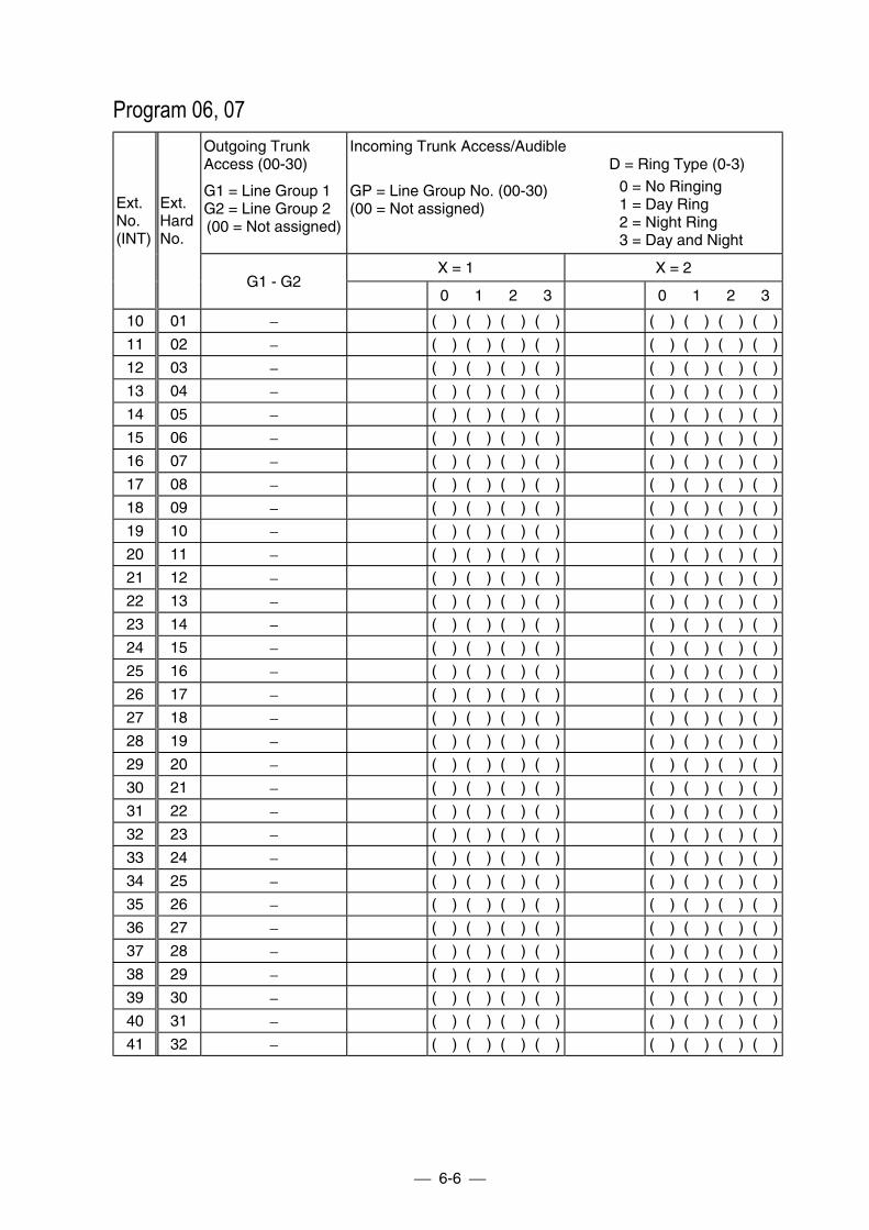
6-6
Program 06, 07Outgoing TrunkAccess (00-30)
G1 = Line Group 1G2 = Line Group 2(00 = Not assigned)
Incoming Trunk Access/Audible
GP = Line Group No. (00-30)(00 = Not assigned)
D = Ring Type (0-3)0 = No Ringing1 = Day Ring2 = Night Ring3 = Day and Night
X = 1 X = 2
Ext.No.(INT)
Ext.HardNo.
G1 - G20 1 2 3 0 1 2 3
10 01 − ( ) ( ) ( ) ( ) ( ) ( ) ( ) ( )
11 02 − ( ) ( ) ( ) ( ) ( ) ( ) ( ) ( )
12 03 − ( ) ( ) ( ) ( ) ( ) ( ) ( ) ( )
13 04 − ( ) ( ) ( ) ( ) ( ) ( ) ( ) ( )
14 05 − ( ) ( ) ( ) ( ) ( ) ( ) ( ) ( )
15 06 − ( ) ( ) ( ) ( ) ( ) ( ) ( ) ( )
16 07 − ( ) ( ) ( ) ( ) ( ) ( ) ( ) ( )
17 08 − ( ) ( ) ( ) ( ) ( ) ( ) ( ) ( )
18 09 − ( ) ( ) ( ) ( ) ( ) ( ) ( ) ( )
19 10 − ( ) ( ) ( ) ( ) ( ) ( ) ( ) ( )
20 11 − ( ) ( ) ( ) ( ) ( ) ( ) ( ) ( )
21 12 − ( ) ( ) ( ) ( ) ( ) ( ) ( ) ( )
22 13 − ( ) ( ) ( ) ( ) ( ) ( ) ( ) ( )
23 14 − ( ) ( ) ( ) ( ) ( ) ( ) ( ) ( )
24 15 − ( ) ( ) ( ) ( ) ( ) ( ) ( ) ( )
25 16 − ( ) ( ) ( ) ( ) ( ) ( ) ( ) ( )
26 17 − ( ) ( ) ( ) ( ) ( ) ( ) ( ) ( )
27 18 − ( ) ( ) ( ) ( ) ( ) ( ) ( ) ( )
28 19 − ( ) ( ) ( ) ( ) ( ) ( ) ( ) ( )
29 20 − ( ) ( ) ( ) ( ) ( ) ( ) ( ) ( )
30 21 − ( ) ( ) ( ) ( ) ( ) ( ) ( ) ( )
31 22 − ( ) ( ) ( ) ( ) ( ) ( ) ( ) ( )
32 23 − ( ) ( ) ( ) ( ) ( ) ( ) ( ) ( )
33 24 − ( ) ( ) ( ) ( ) ( ) ( ) ( ) ( )
34 25 − ( ) ( ) ( ) ( ) ( ) ( ) ( ) ( )
35 26 − ( ) ( ) ( ) ( ) ( ) ( ) ( ) ( )
36 27 − ( ) ( ) ( ) ( ) ( ) ( ) ( ) ( )
37 28 − ( ) ( ) ( ) ( ) ( ) ( ) ( ) ( )
38 29 − ( ) ( ) ( ) ( ) ( ) ( ) ( ) ( )
39 30 − ( ) ( ) ( ) ( ) ( ) ( ) ( ) ( )
40 31 − ( ) ( ) ( ) ( ) ( ) ( ) ( ) ( )
41 32 − ( ) ( ) ( ) ( ) ( ) ( ) ( ) ( )
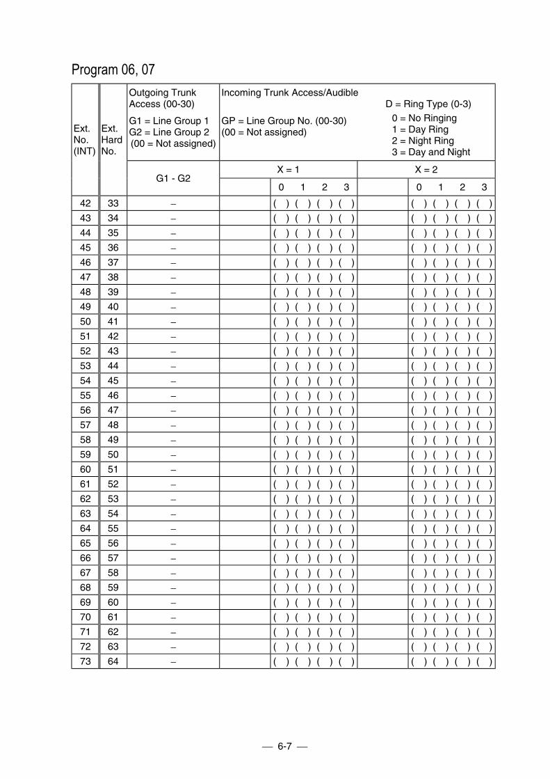
6-7
Program 06, 07Outgoing TrunkAccess (00-30)
G1 = Line Group 1G2 = Line Group 2(00 = Not assigned)
Incoming Trunk Access/Audible
GP = Line Group No. (00-30)(00 = Not assigned)
D = Ring Type (0-3)0 = No Ringing1 = Day Ring2 = Night Ring3 = Day and Night
X = 1 X = 2
Ext.No.(INT)
Ext.HardNo.
G1 - G20 1 2 3 0 1 2 3
42 33 − ( ) ( ) ( ) ( ) ( ) ( ) ( ) ( )
43 34 − ( ) ( ) ( ) ( ) ( ) ( ) ( ) ( )
44 35 − ( ) ( ) ( ) ( ) ( ) ( ) ( ) ( )
45 36 − ( ) ( ) ( ) ( ) ( ) ( ) ( ) ( )
46 37 − ( ) ( ) ( ) ( ) ( ) ( ) ( ) ( )
47 38 − ( ) ( ) ( ) ( ) ( ) ( ) ( ) ( )
48 39 − ( ) ( ) ( ) ( ) ( ) ( ) ( ) ( )
49 40 − ( ) ( ) ( ) ( ) ( ) ( ) ( ) ( )
50 41 − ( ) ( ) ( ) ( ) ( ) ( ) ( ) ( )
51 42 − ( ) ( ) ( ) ( ) ( ) ( ) ( ) ( )
52 43 − ( ) ( ) ( ) ( ) ( ) ( ) ( ) ( )
53 44 − ( ) ( ) ( ) ( ) ( ) ( ) ( ) ( )
54 45 − ( ) ( ) ( ) ( ) ( ) ( ) ( ) ( )
55 46 − ( ) ( ) ( ) ( ) ( ) ( ) ( ) ( )
56 47 − ( ) ( ) ( ) ( ) ( ) ( ) ( ) ( )
57 48 − ( ) ( ) ( ) ( ) ( ) ( ) ( ) ( )
58 49 − ( ) ( ) ( ) ( ) ( ) ( ) ( ) ( )
59 50 − ( ) ( ) ( ) ( ) ( ) ( ) ( ) ( )
60 51 − ( ) ( ) ( ) ( ) ( ) ( ) ( ) ( )
61 52 − ( ) ( ) ( ) ( ) ( ) ( ) ( ) ( )
62 53 − ( ) ( ) ( ) ( ) ( ) ( ) ( ) ( )
63 54 − ( ) ( ) ( ) ( ) ( ) ( ) ( ) ( )
64 55 − ( ) ( ) ( ) ( ) ( ) ( ) ( ) ( )
65 56 − ( ) ( ) ( ) ( ) ( ) ( ) ( ) ( )
66 57 − ( ) ( ) ( ) ( ) ( ) ( ) ( ) ( )
67 58 − ( ) ( ) ( ) ( ) ( ) ( ) ( ) ( )
68 59 − ( ) ( ) ( ) ( ) ( ) ( ) ( ) ( )
69 60 − ( ) ( ) ( ) ( ) ( ) ( ) ( ) ( )
70 61 − ( ) ( ) ( ) ( ) ( ) ( ) ( ) ( )
71 62 − ( ) ( ) ( ) ( ) ( ) ( ) ( ) ( )
72 63 − ( ) ( ) ( ) ( ) ( ) ( ) ( ) ( )
73 64 − ( ) ( ) ( ) ( ) ( ) ( ) ( ) ( )
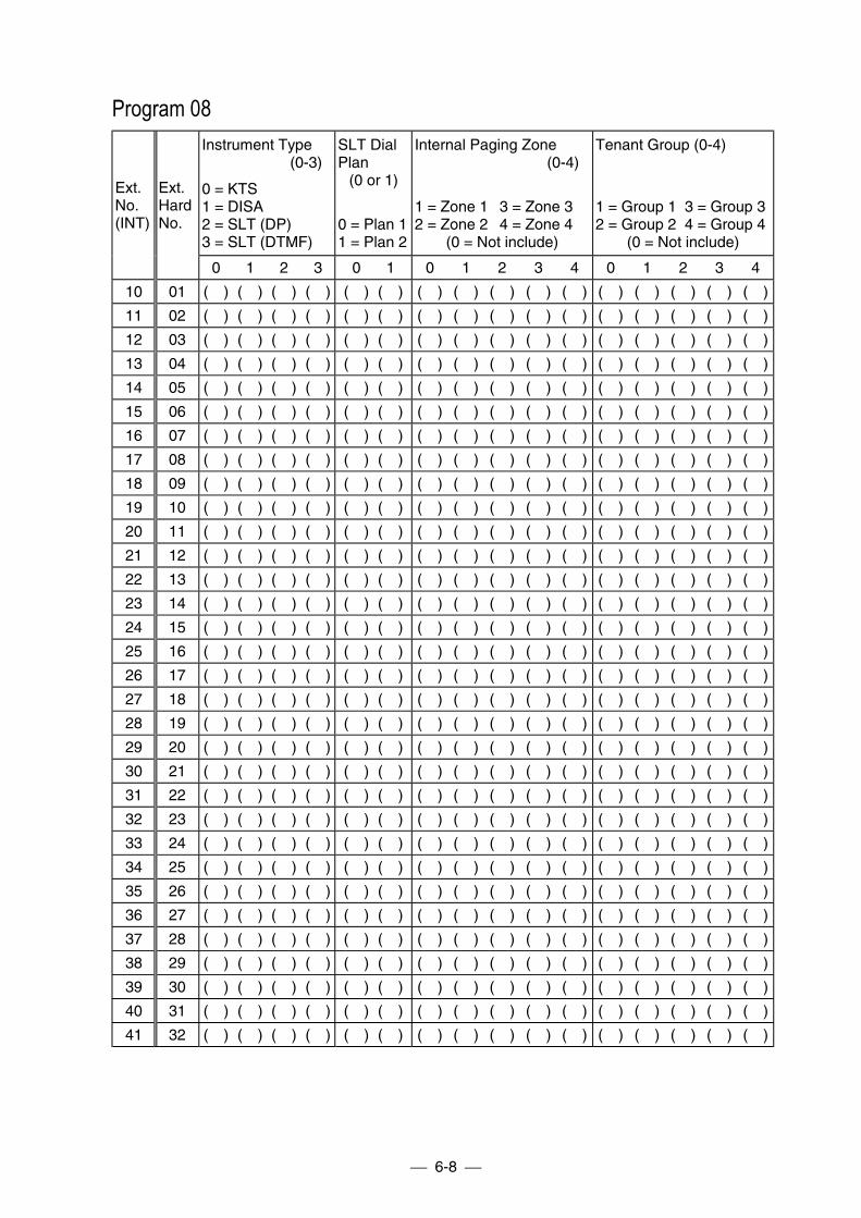
6-8
Program 08Instrument Type
(0-3)
0 = KTS1 = DISA2 = SLT (DP)3 = SLT (DTMF)
SLT DialPlan
(0 or 1)
0 = Plan 11 = Plan 2
Internal Paging Zone(0-4)
1 = Zone 1 3 = Zone 32 = Zone 2 4 = Zone 4
(0 = Not include)
Tenant Group (0-4)
1 = Group 1 3 = Group 32 = Group 2 4 = Group 4
(0 = Not include)
Ext.No.(INT)
Ext.HardNo.
0 1 2 3 0 1 0 1 2 3 4 0 1 2 3 4
10 01 ( ) ( ) ( ) ( ) ( ) ( ) ( ) ( ) ( ) ( ) ( ) ( ) ( ) ( ) ( ) ( )
11 02 ( ) ( ) ( ) ( ) ( ) ( ) ( ) ( ) ( ) ( ) ( ) ( ) ( ) ( ) ( ) ( )
12 03 ( ) ( ) ( ) ( ) ( ) ( ) ( ) ( ) ( ) ( ) ( ) ( ) ( ) ( ) ( ) ( )
13 04 ( ) ( ) ( ) ( ) ( ) ( ) ( ) ( ) ( ) ( ) ( ) ( ) ( ) ( ) ( ) ( )
14 05 ( ) ( ) ( ) ( ) ( ) ( ) ( ) ( ) ( ) ( ) ( ) ( ) ( ) ( ) ( ) ( )
15 06 ( ) ( ) ( ) ( ) ( ) ( ) ( ) ( ) ( ) ( ) ( ) ( ) ( ) ( ) ( ) ( )
16 07 ( ) ( ) ( ) ( ) ( ) ( ) ( ) ( ) ( ) ( ) ( ) ( ) ( ) ( ) ( ) ( )
17 08 ( ) ( ) ( ) ( ) ( ) ( ) ( ) ( ) ( ) ( ) ( ) ( ) ( ) ( ) ( ) ( )
18 09 ( ) ( ) ( ) ( ) ( ) ( ) ( ) ( ) ( ) ( ) ( ) ( ) ( ) ( ) ( ) ( )
19 10 ( ) ( ) ( ) ( ) ( ) ( ) ( ) ( ) ( ) ( ) ( ) ( ) ( ) ( ) ( ) ( )
20 11 ( ) ( ) ( ) ( ) ( ) ( ) ( ) ( ) ( ) ( ) ( ) ( ) ( ) ( ) ( ) ( )
21 12 ( ) ( ) ( ) ( ) ( ) ( ) ( ) ( ) ( ) ( ) ( ) ( ) ( ) ( ) ( ) ( )
22 13 ( ) ( ) ( ) ( ) ( ) ( ) ( ) ( ) ( ) ( ) ( ) ( ) ( ) ( ) ( ) ( )
23 14 ( ) ( ) ( ) ( ) ( ) ( ) ( ) ( ) ( ) ( ) ( ) ( ) ( ) ( ) ( ) ( )
24 15 ( ) ( ) ( ) ( ) ( ) ( ) ( ) ( ) ( ) ( ) ( ) ( ) ( ) ( ) ( ) ( )
25 16 ( ) ( ) ( ) ( ) ( ) ( ) ( ) ( ) ( ) ( ) ( ) ( ) ( ) ( ) ( ) ( )
26 17 ( ) ( ) ( ) ( ) ( ) ( ) ( ) ( ) ( ) ( ) ( ) ( ) ( ) ( ) ( ) ( )
27 18 ( ) ( ) ( ) ( ) ( ) ( ) ( ) ( ) ( ) ( ) ( ) ( ) ( ) ( ) ( ) ( )
28 19 ( ) ( ) ( ) ( ) ( ) ( ) ( ) ( ) ( ) ( ) ( ) ( ) ( ) ( ) ( ) ( )
29 20 ( ) ( ) ( ) ( ) ( ) ( ) ( ) ( ) ( ) ( ) ( ) ( ) ( ) ( ) ( ) ( )
30 21 ( ) ( ) ( ) ( ) ( ) ( ) ( ) ( ) ( ) ( ) ( ) ( ) ( ) ( ) ( ) ( )
31 22 ( ) ( ) ( ) ( ) ( ) ( ) ( ) ( ) ( ) ( ) ( ) ( ) ( ) ( ) ( ) ( )
32 23 ( ) ( ) ( ) ( ) ( ) ( ) ( ) ( ) ( ) ( ) ( ) ( ) ( ) ( ) ( ) ( )
33 24 ( ) ( ) ( ) ( ) ( ) ( ) ( ) ( ) ( ) ( ) ( ) ( ) ( ) ( ) ( ) ( )
34 25 ( ) ( ) ( ) ( ) ( ) ( ) ( ) ( ) ( ) ( ) ( ) ( ) ( ) ( ) ( ) ( )
35 26 ( ) ( ) ( ) ( ) ( ) ( ) ( ) ( ) ( ) ( ) ( ) ( ) ( ) ( ) ( ) ( )
36 27 ( ) ( ) ( ) ( ) ( ) ( ) ( ) ( ) ( ) ( ) ( ) ( ) ( ) ( ) ( ) ( )
37 28 ( ) ( ) ( ) ( ) ( ) ( ) ( ) ( ) ( ) ( ) ( ) ( ) ( ) ( ) ( ) ( )
38 29 ( ) ( ) ( ) ( ) ( ) ( ) ( ) ( ) ( ) ( ) ( ) ( ) ( ) ( ) ( ) ( )
39 30 ( ) ( ) ( ) ( ) ( ) ( ) ( ) ( ) ( ) ( ) ( ) ( ) ( ) ( ) ( ) ( )
40 31 ( ) ( ) ( ) ( ) ( ) ( ) ( ) ( ) ( ) ( ) ( ) ( ) ( ) ( ) ( ) ( )
41 32 ( ) ( ) ( ) ( ) ( ) ( ) ( ) ( ) ( ) ( ) ( ) ( ) ( ) ( ) ( ) ( )
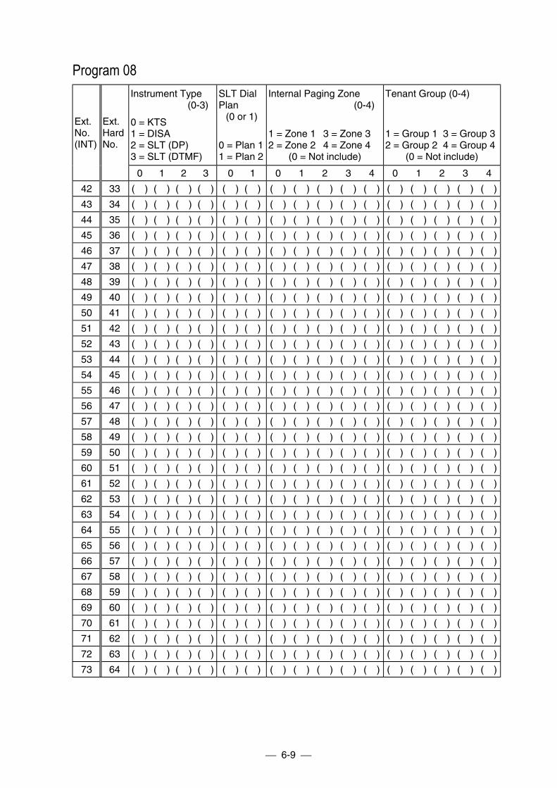
6-9
Program 08Instrument Type
(0-3)
0 = KTS1 = DISA2 = SLT (DP)3 = SLT (DTMF)
SLT DialPlan
(0 or 1)
0 = Plan 11 = Plan 2
Internal Paging Zone(0-4)
1 = Zone 1 3 = Zone 32 = Zone 2 4 = Zone 4
(0 = Not include)
Tenant Group (0-4)
1 = Group 1 3 = Group 32 = Group 2 4 = Group 4
(0 = Not include)
Ext.No.(INT)
Ext.HardNo.
0 1 2 3 0 1 0 1 2 3 4 0 1 2 3 4
42 33 ( ) ( ) ( ) ( ) ( ) ( ) ( ) ( ) ( ) ( ) ( ) ( ) ( ) ( ) ( ) ( )
43 34 ( ) ( ) ( ) ( ) ( ) ( ) ( ) ( ) ( ) ( ) ( ) ( ) ( ) ( ) ( ) ( )
44 35 ( ) ( ) ( ) ( ) ( ) ( ) ( ) ( ) ( ) ( ) ( ) ( ) ( ) ( ) ( ) ( )
45 36 ( ) ( ) ( ) ( ) ( ) ( ) ( ) ( ) ( ) ( ) ( ) ( ) ( ) ( ) ( ) ( )
46 37 ( ) ( ) ( ) ( ) ( ) ( ) ( ) ( ) ( ) ( ) ( ) ( ) ( ) ( ) ( ) ( )
47 38 ( ) ( ) ( ) ( ) ( ) ( ) ( ) ( ) ( ) ( ) ( ) ( ) ( ) ( ) ( ) ( )
48 39 ( ) ( ) ( ) ( ) ( ) ( ) ( ) ( ) ( ) ( ) ( ) ( ) ( ) ( ) ( ) ( )
49 40 ( ) ( ) ( ) ( ) ( ) ( ) ( ) ( ) ( ) ( ) ( ) ( ) ( ) ( ) ( ) ( )
50 41 ( ) ( ) ( ) ( ) ( ) ( ) ( ) ( ) ( ) ( ) ( ) ( ) ( ) ( ) ( ) ( )
51 42 ( ) ( ) ( ) ( ) ( ) ( ) ( ) ( ) ( ) ( ) ( ) ( ) ( ) ( ) ( ) ( )
52 43 ( ) ( ) ( ) ( ) ( ) ( ) ( ) ( ) ( ) ( ) ( ) ( ) ( ) ( ) ( ) ( )
53 44 ( ) ( ) ( ) ( ) ( ) ( ) ( ) ( ) ( ) ( ) ( ) ( ) ( ) ( ) ( ) ( )
54 45 ( ) ( ) ( ) ( ) ( ) ( ) ( ) ( ) ( ) ( ) ( ) ( ) ( ) ( ) ( ) ( )
55 46 ( ) ( ) ( ) ( ) ( ) ( ) ( ) ( ) ( ) ( ) ( ) ( ) ( ) ( ) ( ) ( )
56 47 ( ) ( ) ( ) ( ) ( ) ( ) ( ) ( ) ( ) ( ) ( ) ( ) ( ) ( ) ( ) ( )
57 48 ( ) ( ) ( ) ( ) ( ) ( ) ( ) ( ) ( ) ( ) ( ) ( ) ( ) ( ) ( ) ( )
58 49 ( ) ( ) ( ) ( ) ( ) ( ) ( ) ( ) ( ) ( ) ( ) ( ) ( ) ( ) ( ) ( )
59 50 ( ) ( ) ( ) ( ) ( ) ( ) ( ) ( ) ( ) ( ) ( ) ( ) ( ) ( ) ( ) ( )
60 51 ( ) ( ) ( ) ( ) ( ) ( ) ( ) ( ) ( ) ( ) ( ) ( ) ( ) ( ) ( ) ( )
61 52 ( ) ( ) ( ) ( ) ( ) ( ) ( ) ( ) ( ) ( ) ( ) ( ) ( ) ( ) ( ) ( )
62 53 ( ) ( ) ( ) ( ) ( ) ( ) ( ) ( ) ( ) ( ) ( ) ( ) ( ) ( ) ( ) ( )
63 54 ( ) ( ) ( ) ( ) ( ) ( ) ( ) ( ) ( ) ( ) ( ) ( ) ( ) ( ) ( ) ( )
64 55 ( ) ( ) ( ) ( ) ( ) ( ) ( ) ( ) ( ) ( ) ( ) ( ) ( ) ( ) ( ) ( )
65 56 ( ) ( ) ( ) ( ) ( ) ( ) ( ) ( ) ( ) ( ) ( ) ( ) ( ) ( ) ( ) ( )
66 57 ( ) ( ) ( ) ( ) ( ) ( ) ( ) ( ) ( ) ( ) ( ) ( ) ( ) ( ) ( ) ( )
67 58 ( ) ( ) ( ) ( ) ( ) ( ) ( ) ( ) ( ) ( ) ( ) ( ) ( ) ( ) ( ) ( )
68 59 ( ) ( ) ( ) ( ) ( ) ( ) ( ) ( ) ( ) ( ) ( ) ( ) ( ) ( ) ( ) ( )
69 60 ( ) ( ) ( ) ( ) ( ) ( ) ( ) ( ) ( ) ( ) ( ) ( ) ( ) ( ) ( ) ( )
70 61 ( ) ( ) ( ) ( ) ( ) ( ) ( ) ( ) ( ) ( ) ( ) ( ) ( ) ( ) ( ) ( )
71 62 ( ) ( ) ( ) ( ) ( ) ( ) ( ) ( ) ( ) ( ) ( ) ( ) ( ) ( ) ( ) ( )
72 63 ( ) ( ) ( ) ( ) ( ) ( ) ( ) ( ) ( ) ( ) ( ) ( ) ( ) ( ) ( ) ( )
73 64 ( ) ( ) ( ) ( ) ( ) ( ) ( ) ( ) ( ) ( ) ( ) ( ) ( ) ( ) ( ) ( )

6-10
Program 08, 13Park Hold Group (0-4)
1 = Group 1 3 = Group 32 = Group 2 4 = Group 4
(0 = Not include)
Key Touch Tone(0 or 1)
0 = Enabled1 = Disabled
Do Not Disturb (0-3)
0 = Disabled1 = Trunk calls blocked2 = Trunk and ICM calls blocked3 = Trunk calls blocked or Trunk
and ICM calls blocked
Ext.No.(INT)
Ext.HardNo.
0 1 2 3 4 0 1 0 1 2 3
10 01 ( ) ( ) ( ) ( ) ( ) ( ) ( ) ( ) ( ) ( ) ( )
11 02 ( ) ( ) ( ) ( ) ( ) ( ) ( ) ( ) ( ) ( ) ( )
12 03 ( ) ( ) ( ) ( ) ( ) ( ) ( ) ( ) ( ) ( ) ( )
13 04 ( ) ( ) ( ) ( ) ( ) ( ) ( ) ( ) ( ) ( ) ( )
14 05 ( ) ( ) ( ) ( ) ( ) ( ) ( ) ( ) ( ) ( ) ( )
15 06 ( ) ( ) ( ) ( ) ( ) ( ) ( ) ( ) ( ) ( ) ( )
16 07 ( ) ( ) ( ) ( ) ( ) ( ) ( ) ( ) ( ) ( ) ( )
17 08 ( ) ( ) ( ) ( ) ( ) ( ) ( ) ( ) ( ) ( ) ( )
18 09 ( ) ( ) ( ) ( ) ( ) ( ) ( ) ( ) ( ) ( ) ( )
19 10 ( ) ( ) ( ) ( ) ( ) ( ) ( ) ( ) ( ) ( ) ( )
20 11 ( ) ( ) ( ) ( ) ( ) ( ) ( ) ( ) ( ) ( ) ( )
21 12 ( ) ( ) ( ) ( ) ( ) ( ) ( ) ( ) ( ) ( ) ( )
22 13 ( ) ( ) ( ) ( ) ( ) ( ) ( ) ( ) ( ) ( ) ( )
23 14 ( ) ( ) ( ) ( ) ( ) ( ) ( ) ( ) ( ) ( ) ( )
24 15 ( ) ( ) ( ) ( ) ( ) ( ) ( ) ( ) ( ) ( ) ( )
25 16 ( ) ( ) ( ) ( ) ( ) ( ) ( ) ( ) ( ) ( ) ( )
26 17 ( ) ( ) ( ) ( ) ( ) ( ) ( ) ( ) ( ) ( ) ( )
27 18 ( ) ( ) ( ) ( ) ( ) ( ) ( ) ( ) ( ) ( ) ( )
28 19 ( ) ( ) ( ) ( ) ( ) ( ) ( ) ( ) ( ) ( ) ( )
29 20 ( ) ( ) ( ) ( ) ( ) ( ) ( ) ( ) ( ) ( ) ( )
30 21 ( ) ( ) ( ) ( ) ( ) ( ) ( ) ( ) ( ) ( ) ( )
31 22 ( ) ( ) ( ) ( ) ( ) ( ) ( ) ( ) ( ) ( ) ( )
32 23 ( ) ( ) ( ) ( ) ( ) ( ) ( ) ( ) ( ) ( ) ( )
33 24 ( ) ( ) ( ) ( ) ( ) ( ) ( ) ( ) ( ) ( ) ( )
34 25 ( ) ( ) ( ) ( ) ( ) ( ) ( ) ( ) ( ) ( ) ( )
35 26 ( ) ( ) ( ) ( ) ( ) ( ) ( ) ( ) ( ) ( ) ( )
36 27 ( ) ( ) ( ) ( ) ( ) ( ) ( ) ( ) ( ) ( ) ( )
37 28 ( ) ( ) ( ) ( ) ( ) ( ) ( ) ( ) ( ) ( ) ( )
38 29 ( ) ( ) ( ) ( ) ( ) ( ) ( ) ( ) ( ) ( ) ( )
39 30 ( ) ( ) ( ) ( ) ( ) ( ) ( ) ( ) ( ) ( ) ( )
40 31 ( ) ( ) ( ) ( ) ( ) ( ) ( ) ( ) ( ) ( ) ( )
41 32 ( ) ( ) ( ) ( ) ( ) ( ) ( ) ( ) ( ) ( ) ( )
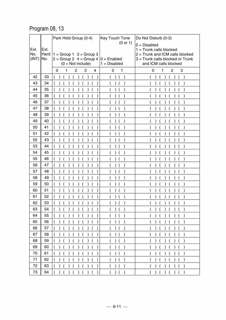
6-11
Program 08, 13Park Hold Group (0-4)
1 = Group 1 3 = Group 32 = Group 2 4 = Group 4
(0 = Not include)
Key Touch Tone(0 or 1)
0 = Enabled1 = Disabled
Do Not Disturb (0-3)
0 = Disabled1 = Trunk calls blocked2 = Trunk and ICM calls blocked3 = Trunk calls blocked or Trunk
and ICM calls blocked
Ext.No.(INT)
Ext.HardNo.
0 1 2 3 4 0 1 0 1 2 3
42 33 ( ) ( ) ( ) ( ) ( ) ( ) ( ) ( ) ( ) ( ) ( )
43 34 ( ) ( ) ( ) ( ) ( ) ( ) ( ) ( ) ( ) ( ) ( )
44 35 ( ) ( ) ( ) ( ) ( ) ( ) ( ) ( ) ( ) ( ) ( )
45 36 ( ) ( ) ( ) ( ) ( ) ( ) ( ) ( ) ( ) ( ) ( )
46 37 ( ) ( ) ( ) ( ) ( ) ( ) ( ) ( ) ( ) ( ) ( )
47 38 ( ) ( ) ( ) ( ) ( ) ( ) ( ) ( ) ( ) ( ) ( )
48 39 ( ) ( ) ( ) ( ) ( ) ( ) ( ) ( ) ( ) ( ) ( )
49 40 ( ) ( ) ( ) ( ) ( ) ( ) ( ) ( ) ( ) ( ) ( )
50 41 ( ) ( ) ( ) ( ) ( ) ( ) ( ) ( ) ( ) ( ) ( )
51 42 ( ) ( ) ( ) ( ) ( ) ( ) ( ) ( ) ( ) ( ) ( )
52 43 ( ) ( ) ( ) ( ) ( ) ( ) ( ) ( ) ( ) ( ) ( )
53 44 ( ) ( ) ( ) ( ) ( ) ( ) ( ) ( ) ( ) ( ) ( )
54 45 ( ) ( ) ( ) ( ) ( ) ( ) ( ) ( ) ( ) ( ) ( )
55 46 ( ) ( ) ( ) ( ) ( ) ( ) ( ) ( ) ( ) ( ) ( )
56 47 ( ) ( ) ( ) ( ) ( ) ( ) ( ) ( ) ( ) ( ) ( )
57 48 ( ) ( ) ( ) ( ) ( ) ( ) ( ) ( ) ( ) ( ) ( )
58 49 ( ) ( ) ( ) ( ) ( ) ( ) ( ) ( ) ( ) ( ) ( )
59 50 ( ) ( ) ( ) ( ) ( ) ( ) ( ) ( ) ( ) ( ) ( )
60 51 ( ) ( ) ( ) ( ) ( ) ( ) ( ) ( ) ( ) ( ) ( )
61 52 ( ) ( ) ( ) ( ) ( ) ( ) ( ) ( ) ( ) ( ) ( )
62 53 ( ) ( ) ( ) ( ) ( ) ( ) ( ) ( ) ( ) ( ) ( )
63 54 ( ) ( ) ( ) ( ) ( ) ( ) ( ) ( ) ( ) ( ) ( )
64 55 ( ) ( ) ( ) ( ) ( ) ( ) ( ) ( ) ( ) ( ) ( )
65 56 ( ) ( ) ( ) ( ) ( ) ( ) ( ) ( ) ( ) ( ) ( )
66 57 ( ) ( ) ( ) ( ) ( ) ( ) ( ) ( ) ( ) ( ) ( )
67 58 ( ) ( ) ( ) ( ) ( ) ( ) ( ) ( ) ( ) ( ) ( )
68 59 ( ) ( ) ( ) ( ) ( ) ( ) ( ) ( ) ( ) ( ) ( )
69 60 ( ) ( ) ( ) ( ) ( ) ( ) ( ) ( ) ( ) ( ) ( )
70 61 ( ) ( ) ( ) ( ) ( ) ( ) ( ) ( ) ( ) ( ) ( )
71 62 ( ) ( ) ( ) ( ) ( ) ( ) ( ) ( ) ( ) ( ) ( )
72 63 ( ) ( ) ( ) ( ) ( ) ( ) ( ) ( ) ( ) ( ) ( )
73 64 ( ) ( ) ( ) ( ) ( ) ( ) ( ) ( ) ( ) ( ) ( )

6-12
Program 13AlarmAudible
(0 or 1)
0 = Off1 = On
Voice AnnounceDevice Port
(0 or 1)
0 = Disable1 = Enable
Terminal Connection(For SLT) (0 or 1)
0 = Not connected1 = Connected
Ext.No.(INT)
Ext.
HardNo.
0 1 0 1 0 1
10 01 ( ) ( ) ( ) ( ) ( ) ( )
11 02 ( ) ( ) ( ) ( ) ( ) ( )
12 03 ( ) ( ) ( ) ( ) ( ) ( )
13 04 ( ) ( ) ( ) ( ) ( ) ( )
14 05 ( ) ( ) ( ) ( ) ( ) ( )
15 06 ( ) ( ) ( ) ( ) ( ) ( )
16 07 ( ) ( ) ( ) ( ) ( ) ( )
17 08 ( ) ( ) ( ) ( ) ( ) ( )
18 09 ( ) ( ) ( ) ( ) ( ) ( )
19 10 ( ) ( ) ( ) ( ) ( ) ( )
20 11 ( ) ( ) ( ) ( ) ( ) ( )
21 12 ( ) ( ) ( ) ( ) ( ) ( )
22 13 ( ) ( ) ( ) ( ) ( ) ( )
23 14 ( ) ( ) ( ) ( ) ( ) ( )
24 15 ( ) ( ) ( ) ( ) ( ) ( )
25 16 ( ) ( ) ( ) ( ) ( ) ( )
26 17 ( ) ( ) ( ) ( ) ( ) ( )
27 18 ( ) ( ) ( ) ( ) ( ) ( )
28 19 ( ) ( ) ( ) ( ) ( ) ( )
29 20 ( ) ( ) ( ) ( ) ( ) ( )
30 21 ( ) ( ) ( ) ( ) ( ) ( )
31 22 ( ) ( ) ( ) ( ) ( ) ( )
32 23 ( ) ( ) ( ) ( ) ( ) ( )
33 24 ( ) ( ) ( ) ( ) ( ) ( )
34 25 ( ) ( ) ( ) ( ) ( ) ( )
35 26 ( ) ( ) ( ) ( ) ( ) ( )
36 27 ( ) ( ) ( ) ( ) ( ) ( )
37 28 ( ) ( ) ( ) ( ) ( ) ( )
38 29 ( ) ( ) ( ) ( ) ( ) ( )
39 30 ( ) ( ) ( ) ( ) ( ) ( )
40 31 ( ) ( ) ( ) ( ) ( ) ( )
41 32 ( ) ( ) ( ) ( ) ( ) ( )
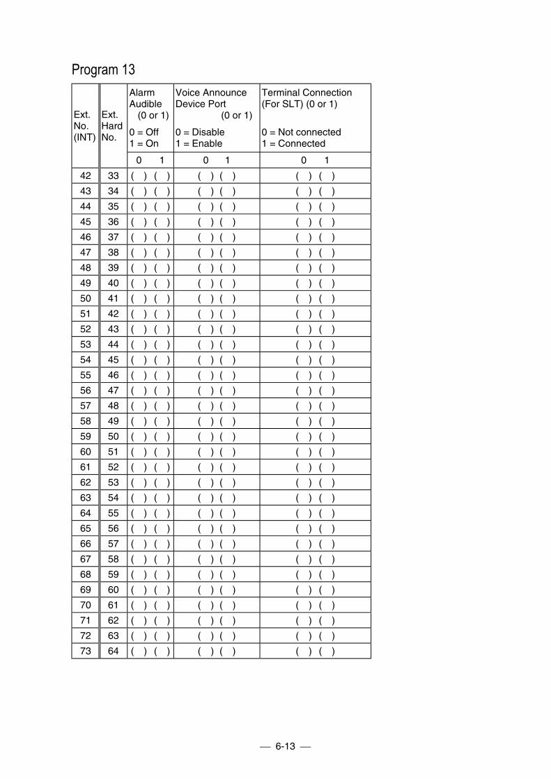
6-13
Program 13AlarmAudible
(0 or 1)
0 = Off1 = On
Voice AnnounceDevice Port
(0 or 1)
0 = Disable1 = Enable
Terminal Connection(For SLT) (0 or 1)
0 = Not connected1 = Connected
Ext.No.(INT)
Ext.HardNo.
0 1 0 1 0 1
42 33 ( ) ( ) ( ) ( ) ( ) ( )
43 34 ( ) ( ) ( ) ( ) ( ) ( )
44 35 ( ) ( ) ( ) ( ) ( ) ( )
45 36 ( ) ( ) ( ) ( ) ( ) ( )
46 37 ( ) ( ) ( ) ( ) ( ) ( )
47 38 ( ) ( ) ( ) ( ) ( ) ( )
48 39 ( ) ( ) ( ) ( ) ( ) ( )
49 40 ( ) ( ) ( ) ( ) ( ) ( )
50 41 ( ) ( ) ( ) ( ) ( ) ( )
51 42 ( ) ( ) ( ) ( ) ( ) ( )
52 43 ( ) ( ) ( ) ( ) ( ) ( )
53 44 ( ) ( ) ( ) ( ) ( ) ( )
54 45 ( ) ( ) ( ) ( ) ( ) ( )
55 46 ( ) ( ) ( ) ( ) ( ) ( )
56 47 ( ) ( ) ( ) ( ) ( ) ( )
57 48 ( ) ( ) ( ) ( ) ( ) ( )
58 49 ( ) ( ) ( ) ( ) ( ) ( )
59 50 ( ) ( ) ( ) ( ) ( ) ( )
60 51 ( ) ( ) ( ) ( ) ( ) ( )
61 52 ( ) ( ) ( ) ( ) ( ) ( )
62 53 ( ) ( ) ( ) ( ) ( ) ( )
63 54 ( ) ( ) ( ) ( ) ( ) ( )
64 55 ( ) ( ) ( ) ( ) ( ) ( )
65 56 ( ) ( ) ( ) ( ) ( ) ( )
66 57 ( ) ( ) ( ) ( ) ( ) ( )
67 58 ( ) ( ) ( ) ( ) ( ) ( )
68 59 ( ) ( ) ( ) ( ) ( ) ( )
69 60 ( ) ( ) ( ) ( ) ( ) ( )
70 61 ( ) ( ) ( ) ( ) ( ) ( )
71 62 ( ) ( ) ( ) ( ) ( ) ( )
72 63 ( ) ( ) ( ) ( ) ( ) ( )
73 64 ( ) ( ) ( ) ( ) ( ) ( )
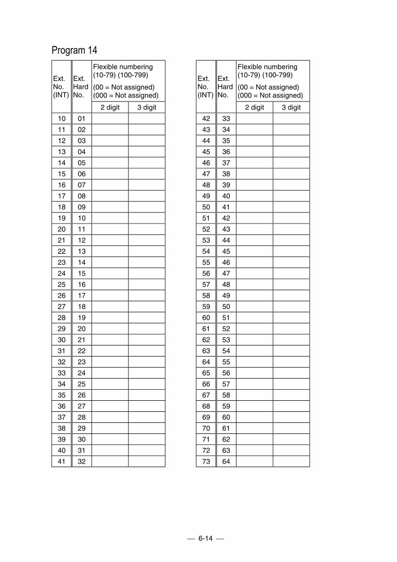
6-14
Program 14Flexible numbering(10-79) (100-799)
(00 = Not assigned)(000 = Not assigned)
Flexible numbering(10-79) (100-799)
(00 = Not assigned)(000 = Not assigned)
Ext.No.(INT)
Ext.HardNo.
2 digit 3 digit
Ext.No.(INT)
Ext.HardNo.
2 digit 3 digit
10 01 42 33
11 02 43 34
12 03 44 35
13 04 45 36
14 05 46 37
15 06 47 38
16 07 48 39
17 08 49 40
18 09 50 41
19 10 51 42
20 11 52 43
21 12 53 44
22 13 54 45
23 14 55 46
24 15 56 47
25 16 57 48
26 17 58 49
27 18 59 50
28 19 60 51
29 20 61 52
30 21 62 53
31 22 63 54
32 23 64 55
33 24 65 56
34 25 66 57
35 26 67 58
36 27 68 59
37 28 69 60
38 29 70 61
39 30 71 62
40 31 72 63
41 32 73 64
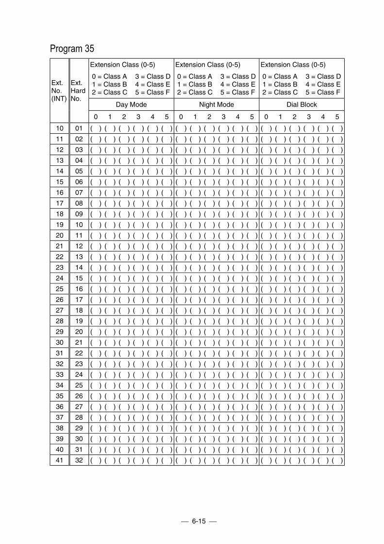
6-15
Program 35Extension Class (0-5)
0 = Class A 3 = Class D1 = Class B 4 = Class E2 = Class C 5 = Class F
Extension Class (0-5)
0 = Class A 3 = Class D1 = Class B 4 = Class E2 = Class C 5 = Class F
Extension Class (0-5)
0 = Class A 3 = Class D1 = Class B 4 = Class E2 = Class C 5 = Class F
Day Mode Night Mode Dial Block
Ext.No.(INT)
Ext.HardNo.
0 1 2 3 4 5 0 1 2 3 4 5 0 1 2 3 4 5
10 01 ( ) ( ) ( ) ( ) ( ) ( ) ( ) ( ) ( ) ( ) ( ) ( ) ( ) ( ) ( ) ( ) ( ) ( )
11 02 ( ) ( ) ( ) ( ) ( ) ( ) ( ) ( ) ( ) ( ) ( ) ( ) ( ) ( ) ( ) ( ) ( ) ( )
12 03 ( ) ( ) ( ) ( ) ( ) ( ) ( ) ( ) ( ) ( ) ( ) ( ) ( ) ( ) ( ) ( ) ( ) ( )
13 04 ( ) ( ) ( ) ( ) ( ) ( ) ( ) ( ) ( ) ( ) ( ) ( ) ( ) ( ) ( ) ( ) ( ) ( )
14 05 ( ) ( ) ( ) ( ) ( ) ( ) ( ) ( ) ( ) ( ) ( ) ( ) ( ) ( ) ( ) ( ) ( ) ( )
15 06 ( ) ( ) ( ) ( ) ( ) ( ) ( ) ( ) ( ) ( ) ( ) ( ) ( ) ( ) ( ) ( ) ( ) ( )
16 07 ( ) ( ) ( ) ( ) ( ) ( ) ( ) ( ) ( ) ( ) ( ) ( ) ( ) ( ) ( ) ( ) ( ) ( )
17 08 ( ) ( ) ( ) ( ) ( ) ( ) ( ) ( ) ( ) ( ) ( ) ( ) ( ) ( ) ( ) ( ) ( ) ( )
18 09 ( ) ( ) ( ) ( ) ( ) ( ) ( ) ( ) ( ) ( ) ( ) ( ) ( ) ( ) ( ) ( ) ( ) ( )
19 10 ( ) ( ) ( ) ( ) ( ) ( ) ( ) ( ) ( ) ( ) ( ) ( ) ( ) ( ) ( ) ( ) ( ) ( )
20 11 ( ) ( ) ( ) ( ) ( ) ( ) ( ) ( ) ( ) ( ) ( ) ( ) ( ) ( ) ( ) ( ) ( ) ( )
21 12 ( ) ( ) ( ) ( ) ( ) ( ) ( ) ( ) ( ) ( ) ( ) ( ) ( ) ( ) ( ) ( ) ( ) ( )
22 13 ( ) ( ) ( ) ( ) ( ) ( ) ( ) ( ) ( ) ( ) ( ) ( ) ( ) ( ) ( ) ( ) ( ) ( )
23 14 ( ) ( ) ( ) ( ) ( ) ( ) ( ) ( ) ( ) ( ) ( ) ( ) ( ) ( ) ( ) ( ) ( ) ( )
24 15 ( ) ( ) ( ) ( ) ( ) ( ) ( ) ( ) ( ) ( ) ( ) ( ) ( ) ( ) ( ) ( ) ( ) ( )
25 16 ( ) ( ) ( ) ( ) ( ) ( ) ( ) ( ) ( ) ( ) ( ) ( ) ( ) ( ) ( ) ( ) ( ) ( )
26 17 ( ) ( ) ( ) ( ) ( ) ( ) ( ) ( ) ( ) ( ) ( ) ( ) ( ) ( ) ( ) ( ) ( ) ( )
27 18 ( ) ( ) ( ) ( ) ( ) ( ) ( ) ( ) ( ) ( ) ( ) ( ) ( ) ( ) ( ) ( ) ( ) ( )
28 19 ( ) ( ) ( ) ( ) ( ) ( ) ( ) ( ) ( ) ( ) ( ) ( ) ( ) ( ) ( ) ( ) ( ) ( )
29 20 ( ) ( ) ( ) ( ) ( ) ( ) ( ) ( ) ( ) ( ) ( ) ( ) ( ) ( ) ( ) ( ) ( ) ( )
30 21 ( ) ( ) ( ) ( ) ( ) ( ) ( ) ( ) ( ) ( ) ( ) ( ) ( ) ( ) ( ) ( ) ( ) ( )
31 22 ( ) ( ) ( ) ( ) ( ) ( ) ( ) ( ) ( ) ( ) ( ) ( ) ( ) ( ) ( ) ( ) ( ) ( )
32 23 ( ) ( ) ( ) ( ) ( ) ( ) ( ) ( ) ( ) ( ) ( ) ( ) ( ) ( ) ( ) ( ) ( ) ( )
33 24 ( ) ( ) ( ) ( ) ( ) ( ) ( ) ( ) ( ) ( ) ( ) ( ) ( ) ( ) ( ) ( ) ( ) ( )
34 25 ( ) ( ) ( ) ( ) ( ) ( ) ( ) ( ) ( ) ( ) ( ) ( ) ( ) ( ) ( ) ( ) ( ) ( )
35 26 ( ) ( ) ( ) ( ) ( ) ( ) ( ) ( ) ( ) ( ) ( ) ( ) ( ) ( ) ( ) ( ) ( ) ( )
36 27 ( ) ( ) ( ) ( ) ( ) ( ) ( ) ( ) ( ) ( ) ( ) ( ) ( ) ( ) ( ) ( ) ( ) ( )
37 28 ( ) ( ) ( ) ( ) ( ) ( ) ( ) ( ) ( ) ( ) ( ) ( ) ( ) ( ) ( ) ( ) ( ) ( )
38 29 ( ) ( ) ( ) ( ) ( ) ( ) ( ) ( ) ( ) ( ) ( ) ( ) ( ) ( ) ( ) ( ) ( ) ( )
39 30 ( ) ( ) ( ) ( ) ( ) ( ) ( ) ( ) ( ) ( ) ( ) ( ) ( ) ( ) ( ) ( ) ( ) ( )
40 31 ( ) ( ) ( ) ( ) ( ) ( ) ( ) ( ) ( ) ( ) ( ) ( ) ( ) ( ) ( ) ( ) ( ) ( )
41 32 ( ) ( ) ( ) ( ) ( ) ( ) ( ) ( ) ( ) ( ) ( ) ( ) ( ) ( ) ( ) ( ) ( ) ( )
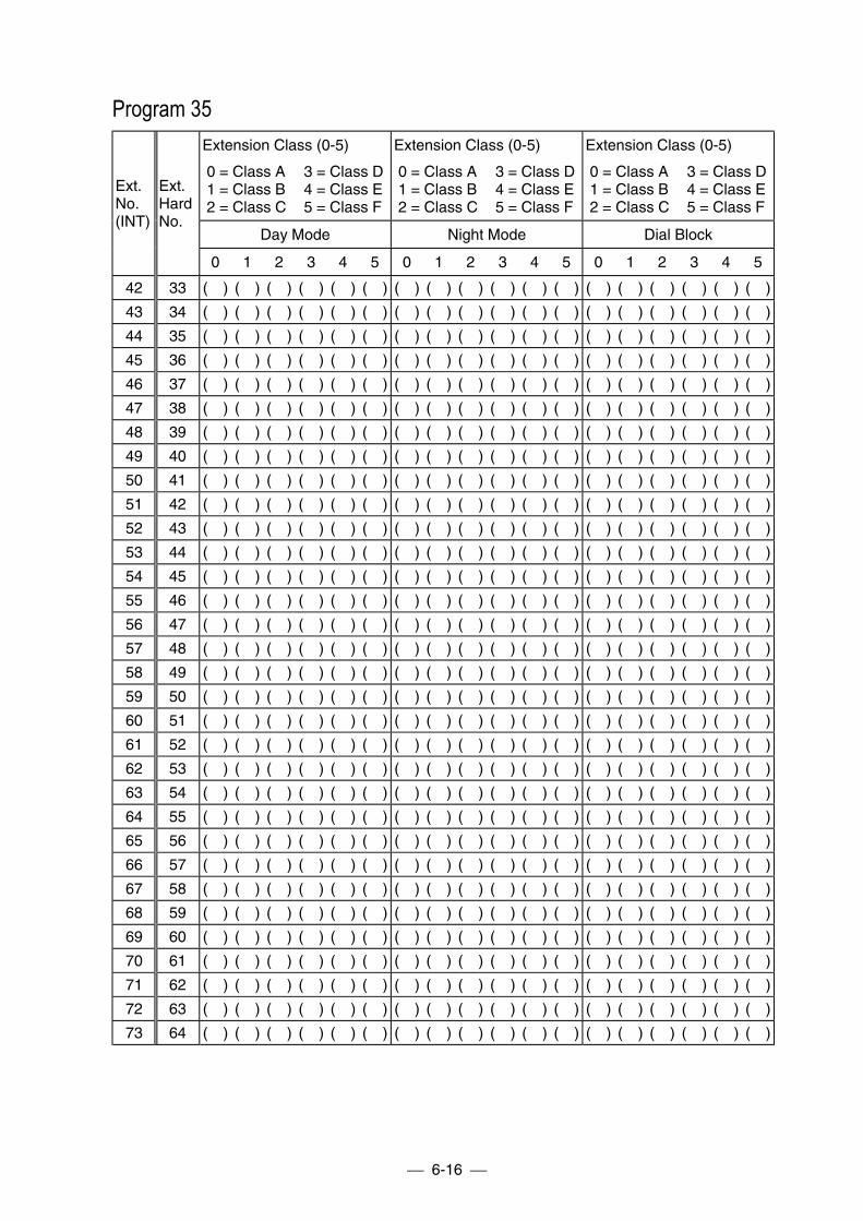
6-16
Program 35Extension Class (0-5)
0 = Class A 3 = Class D1 = Class B 4 = Class E2 = Class C 5 = Class F
Extension Class (0-5)
0 = Class A 3 = Class D1 = Class B 4 = Class E2 = Class C 5 = Class F
Extension Class (0-5)
0 = Class A 3 = Class D1 = Class B 4 = Class E2 = Class C 5 = Class F
Day Mode Night Mode Dial Block
Ext.No.(INT)
Ext.HardNo.
0 1 2 3 4 5 0 1 2 3 4 5 0 1 2 3 4 5
42 33 ( ) ( ) ( ) ( ) ( ) ( ) ( ) ( ) ( ) ( ) ( ) ( ) ( ) ( ) ( ) ( ) ( ) ( )
43 34 ( ) ( ) ( ) ( ) ( ) ( ) ( ) ( ) ( ) ( ) ( ) ( ) ( ) ( ) ( ) ( ) ( ) ( )
44 35 ( ) ( ) ( ) ( ) ( ) ( ) ( ) ( ) ( ) ( ) ( ) ( ) ( ) ( ) ( ) ( ) ( ) ( )
45 36 ( ) ( ) ( ) ( ) ( ) ( ) ( ) ( ) ( ) ( ) ( ) ( ) ( ) ( ) ( ) ( ) ( ) ( )
46 37 ( ) ( ) ( ) ( ) ( ) ( ) ( ) ( ) ( ) ( ) ( ) ( ) ( ) ( ) ( ) ( ) ( ) ( )
47 38 ( ) ( ) ( ) ( ) ( ) ( ) ( ) ( ) ( ) ( ) ( ) ( ) ( ) ( ) ( ) ( ) ( ) ( )
48 39 ( ) ( ) ( ) ( ) ( ) ( ) ( ) ( ) ( ) ( ) ( ) ( ) ( ) ( ) ( ) ( ) ( ) ( )
49 40 ( ) ( ) ( ) ( ) ( ) ( ) ( ) ( ) ( ) ( ) ( ) ( ) ( ) ( ) ( ) ( ) ( ) ( )
50 41 ( ) ( ) ( ) ( ) ( ) ( ) ( ) ( ) ( ) ( ) ( ) ( ) ( ) ( ) ( ) ( ) ( ) ( )
51 42 ( ) ( ) ( ) ( ) ( ) ( ) ( ) ( ) ( ) ( ) ( ) ( ) ( ) ( ) ( ) ( ) ( ) ( )
52 43 ( ) ( ) ( ) ( ) ( ) ( ) ( ) ( ) ( ) ( ) ( ) ( ) ( ) ( ) ( ) ( ) ( ) ( )
53 44 ( ) ( ) ( ) ( ) ( ) ( ) ( ) ( ) ( ) ( ) ( ) ( ) ( ) ( ) ( ) ( ) ( ) ( )
54 45 ( ) ( ) ( ) ( ) ( ) ( ) ( ) ( ) ( ) ( ) ( ) ( ) ( ) ( ) ( ) ( ) ( ) ( )
55 46 ( ) ( ) ( ) ( ) ( ) ( ) ( ) ( ) ( ) ( ) ( ) ( ) ( ) ( ) ( ) ( ) ( ) ( )
56 47 ( ) ( ) ( ) ( ) ( ) ( ) ( ) ( ) ( ) ( ) ( ) ( ) ( ) ( ) ( ) ( ) ( ) ( )
57 48 ( ) ( ) ( ) ( ) ( ) ( ) ( ) ( ) ( ) ( ) ( ) ( ) ( ) ( ) ( ) ( ) ( ) ( )
58 49 ( ) ( ) ( ) ( ) ( ) ( ) ( ) ( ) ( ) ( ) ( ) ( ) ( ) ( ) ( ) ( ) ( ) ( )
59 50 ( ) ( ) ( ) ( ) ( ) ( ) ( ) ( ) ( ) ( ) ( ) ( ) ( ) ( ) ( ) ( ) ( ) ( )
60 51 ( ) ( ) ( ) ( ) ( ) ( ) ( ) ( ) ( ) ( ) ( ) ( ) ( ) ( ) ( ) ( ) ( ) ( )
61 52 ( ) ( ) ( ) ( ) ( ) ( ) ( ) ( ) ( ) ( ) ( ) ( ) ( ) ( ) ( ) ( ) ( ) ( )
62 53 ( ) ( ) ( ) ( ) ( ) ( ) ( ) ( ) ( ) ( ) ( ) ( ) ( ) ( ) ( ) ( ) ( ) ( )
63 54 ( ) ( ) ( ) ( ) ( ) ( ) ( ) ( ) ( ) ( ) ( ) ( ) ( ) ( ) ( ) ( ) ( ) ( )
64 55 ( ) ( ) ( ) ( ) ( ) ( ) ( ) ( ) ( ) ( ) ( ) ( ) ( ) ( ) ( ) ( ) ( ) ( )
65 56 ( ) ( ) ( ) ( ) ( ) ( ) ( ) ( ) ( ) ( ) ( ) ( ) ( ) ( ) ( ) ( ) ( ) ( )
66 57 ( ) ( ) ( ) ( ) ( ) ( ) ( ) ( ) ( ) ( ) ( ) ( ) ( ) ( ) ( ) ( ) ( ) ( )
67 58 ( ) ( ) ( ) ( ) ( ) ( ) ( ) ( ) ( ) ( ) ( ) ( ) ( ) ( ) ( ) ( ) ( ) ( )
68 59 ( ) ( ) ( ) ( ) ( ) ( ) ( ) ( ) ( ) ( ) ( ) ( ) ( ) ( ) ( ) ( ) ( ) ( )
69 60 ( ) ( ) ( ) ( ) ( ) ( ) ( ) ( ) ( ) ( ) ( ) ( ) ( ) ( ) ( ) ( ) ( ) ( )
70 61 ( ) ( ) ( ) ( ) ( ) ( ) ( ) ( ) ( ) ( ) ( ) ( ) ( ) ( ) ( ) ( ) ( ) ( )
71 62 ( ) ( ) ( ) ( ) ( ) ( ) ( ) ( ) ( ) ( ) ( ) ( ) ( ) ( ) ( ) ( ) ( ) ( )
72 63 ( ) ( ) ( ) ( ) ( ) ( ) ( ) ( ) ( ) ( ) ( ) ( ) ( ) ( ) ( ) ( ) ( ) ( )
73 64 ( ) ( ) ( ) ( ) ( ) ( ) ( ) ( ) ( ) ( ) ( ) ( ) ( ) ( ) ( ) ( ) ( ) ( )
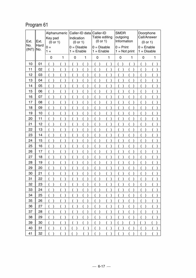
6-17
Program 61AlphanumericKey pad
(0 or 1)0 =1 =
Caller-ID dataIndication (0 or 1)0 = Disable1 = Enable
Caller-IDTable editing (0 or 1)
0 = Disable1 = Enable
SMDRoutgoingInformation
0 = Print1 = Not print
DoorphoneCall/Answer (0 or 1)0 = Enable1 = Disable
Ext.No.(INT)
Ext.HardNo.
0 1 0 1 0 1 0 1 0 1
10 01 ( ) ( ) ( ) ( ) ( ) ( ) ( ) ( ) ( ) ( )
11 02 ( ) ( ) ( ) ( ) ( ) ( ) ( ) ( ) ( ) ( )
12 03 ( ) ( ) ( ) ( ) ( ) ( ) ( ) ( ) ( ) ( )
13 04 ( ) ( ) ( ) ( ) ( ) ( ) ( ) ( ) ( ) ( )
14 05 ( ) ( ) ( ) ( ) ( ) ( ) ( ) ( ) ( ) ( )
15 06 ( ) ( ) ( ) ( ) ( ) ( ) ( ) ( ) ( ) ( )
16 07 ( ) ( ) ( ) ( ) ( ) ( ) ( ) ( ) ( ) ( )
17 08 ( ) ( ) ( ) ( ) ( ) ( ) ( ) ( ) ( ) ( )
18 09 ( ) ( ) ( ) ( ) ( ) ( ) ( ) ( ) ( ) ( )
19 10 ( ) ( ) ( ) ( ) ( ) ( ) ( ) ( ) ( ) ( )
20 11 ( ) ( ) ( ) ( ) ( ) ( ) ( ) ( ) ( ) ( )
21 12 ( ) ( ) ( ) ( ) ( ) ( ) ( ) ( ) ( ) ( )
22 13 ( ) ( ) ( ) ( ) ( ) ( ) ( ) ( ) ( ) ( )
23 14 ( ) ( ) ( ) ( ) ( ) ( ) ( ) ( ) ( ) ( )
24 15 ( ) ( ) ( ) ( ) ( ) ( ) ( ) ( ) ( ) ( )
25 16 ( ) ( ) ( ) ( ) ( ) ( ) ( ) ( ) ( ) ( )
26 17 ( ) ( ) ( ) ( ) ( ) ( ) ( ) ( ) ( ) ( )
27 18 ( ) ( ) ( ) ( ) ( ) ( ) ( ) ( ) ( ) ( )
28 19 ( ) ( ) ( ) ( ) ( ) ( ) ( ) ( ) ( ) ( )
29 20 ( ) ( ) ( ) ( ) ( ) ( ) ( ) ( ) ( ) ( )
30 21 ( ) ( ) ( ) ( ) ( ) ( ) ( ) ( ) ( ) ( )
31 22 ( ) ( ) ( ) ( ) ( ) ( ) ( ) ( ) ( ) ( )
32 23 ( ) ( ) ( ) ( ) ( ) ( ) ( ) ( ) ( ) ( )
33 24 ( ) ( ) ( ) ( ) ( ) ( ) ( ) ( ) ( ) ( )
34 25 ( ) ( ) ( ) ( ) ( ) ( ) ( ) ( ) ( ) ( )
35 26 ( ) ( ) ( ) ( ) ( ) ( ) ( ) ( ) ( ) ( )
36 27 ( ) ( ) ( ) ( ) ( ) ( ) ( ) ( ) ( ) ( )
37 28 ( ) ( ) ( ) ( ) ( ) ( ) ( ) ( ) ( ) ( )
38 29 ( ) ( ) ( ) ( ) ( ) ( ) ( ) ( ) ( ) ( )
39 30 ( ) ( ) ( ) ( ) ( ) ( ) ( ) ( ) ( ) ( )
40 31 ( ) ( ) ( ) ( ) ( ) ( ) ( ) ( ) ( ) ( )
41 32 ( ) ( ) ( ) ( ) ( ) ( ) ( ) ( ) ( ) ( )
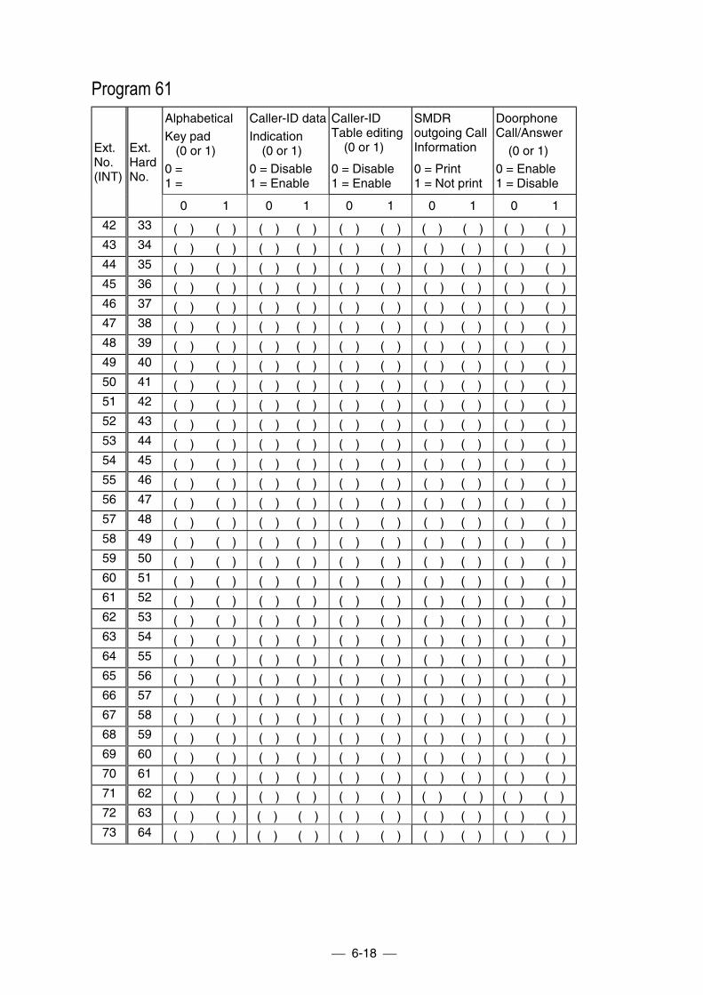
6-18
Program 61AlphabeticalKey pad
(0 or 1)0 =1 =
Caller-ID dataIndication (0 or 1)0 = Disable1 = Enable
Caller-IDTable editing (0 or 1)
0 = Disable1 = Enable
SMDRoutgoing CallInformation
0 = Print1 = Not print
DoorphoneCall/Answer (0 or 1)0 = Enable1 = Disable
Ext.No.(INT)
Ext.HardNo.
0 1 0 1 0 1 0 1 0 1
42 33 ( ) ( ) ( ) ( ) ( ) ( ) ( ) ( ) ( ) ( )43 34 ( ) ( ) ( ) ( ) ( ) ( ) ( ) ( ) ( ) ( )44 35 ( ) ( ) ( ) ( ) ( ) ( ) ( ) ( ) ( ) ( )45 36 ( ) ( ) ( ) ( ) ( ) ( ) ( ) ( ) ( ) ( )46 37 ( ) ( ) ( ) ( ) ( ) ( ) ( ) ( ) ( ) ( )47 38 ( ) ( ) ( ) ( ) ( ) ( ) ( ) ( ) ( ) ( )48 39 ( ) ( ) ( ) ( ) ( ) ( ) ( ) ( ) ( ) ( )49 40 ( ) ( ) ( ) ( ) ( ) ( ) ( ) ( ) ( ) ( )50 41 ( ) ( ) ( ) ( ) ( ) ( ) ( ) ( ) ( ) ( )51 42 ( ) ( ) ( ) ( ) ( ) ( ) ( ) ( ) ( ) ( )52 43 ( ) ( ) ( ) ( ) ( ) ( ) ( ) ( ) ( ) ( )53 44 ( ) ( ) ( ) ( ) ( ) ( ) ( ) ( ) ( ) ( )54 45 ( ) ( ) ( ) ( ) ( ) ( ) ( ) ( ) ( ) ( )55 46 ( ) ( ) ( ) ( ) ( ) ( ) ( ) ( ) ( ) ( )56 47 ( ) ( ) ( ) ( ) ( ) ( ) ( ) ( ) ( ) ( )57 48 ( ) ( ) ( ) ( ) ( ) ( ) ( ) ( ) ( ) ( )58 49 ( ) ( ) ( ) ( ) ( ) ( ) ( ) ( ) ( ) ( )59 50 ( ) ( ) ( ) ( ) ( ) ( ) ( ) ( ) ( ) ( )60 51 ( ) ( ) ( ) ( ) ( ) ( ) ( ) ( ) ( ) ( )61 52 ( ) ( ) ( ) ( ) ( ) ( ) ( ) ( ) ( ) ( )62 53 ( ) ( ) ( ) ( ) ( ) ( ) ( ) ( ) ( ) ( )63 54 ( ) ( ) ( ) ( ) ( ) ( ) ( ) ( ) ( ) ( )64 55 ( ) ( ) ( ) ( ) ( ) ( ) ( ) ( ) ( ) ( )65 56 ( ) ( ) ( ) ( ) ( ) ( ) ( ) ( ) ( ) ( )66 57 ( ) ( ) ( ) ( ) ( ) ( ) ( ) ( ) ( ) ( )67 58 ( ) ( ) ( ) ( ) ( ) ( ) ( ) ( ) ( ) ( )68 59 ( ) ( ) ( ) ( ) ( ) ( ) ( ) ( ) ( ) ( )69 60 ( ) ( ) ( ) ( ) ( ) ( ) ( ) ( ) ( ) ( )70 61 ( ) ( ) ( ) ( ) ( ) ( ) ( ) ( ) ( ) ( )71 62 ( ) ( ) ( ) ( ) ( ) ( ) ( ) ( ) ( ) ( )72 63 ( ) ( ) ( ) ( ) ( ) ( ) ( ) ( ) ( ) ( )73 64 ( ) ( ) ( ) ( ) ( ) ( ) ( ) ( ) ( ) ( )
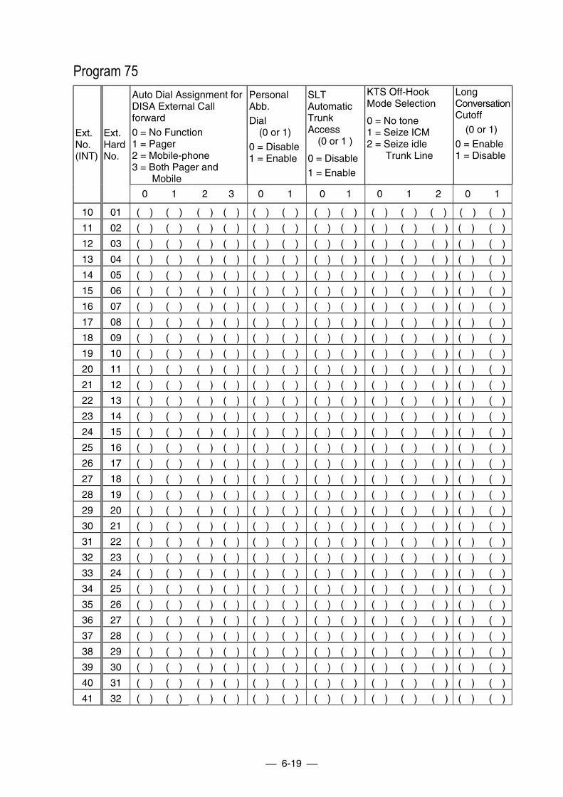
6-19
Program 75Auto Dial Assignment forDISA External Callforward0 = No Function1 = Pager2 = Mobile-phone3 = Both Pager and Mobile
PersonalAbb.Dial (0 or 1)0 = Disable1 = Enable
SLTAutomaticTrunkAccess (0 or 1 )
0 = Disable1 = Enable
KTS Off-HookMode Selection
0 = No tone1 = Seize ICM2 = Seize idle
Trunk Line
LongConversationCutoff (0 or 1)0 = Enable1 = Disable
Ext.No.(INT)
Ext.HardNo.
0 1 2 3 0 1 0 1 0 1 2 0 1
10 01 ( ) ( ) ( ) ( ) ( ) ( ) ( ) ( ) ( ) ( ) ( ) ( ) ( )
11 02 ( ) ( ) ( ) ( ) ( ) ( ) ( ) ( ) ( ) ( ) ( ) ( ) ( )
12 03 ( ) ( ) ( ) ( ) ( ) ( ) ( ) ( ) ( ) ( ) ( ) ( ) ( )
13 04 ( ) ( ) ( ) ( ) ( ) ( ) ( ) ( ) ( ) ( ) ( ) ( ) ( )
14 05 ( ) ( ) ( ) ( ) ( ) ( ) ( ) ( ) ( ) ( ) ( ) ( ) ( )
15 06 ( ) ( ) ( ) ( ) ( ) ( ) ( ) ( ) ( ) ( ) ( ) ( ) ( )
16 07 ( ) ( ) ( ) ( ) ( ) ( ) ( ) ( ) ( ) ( ) ( ) ( ) ( )
17 08 ( ) ( ) ( ) ( ) ( ) ( ) ( ) ( ) ( ) ( ) ( ) ( ) ( )
18 09 ( ) ( ) ( ) ( ) ( ) ( ) ( ) ( ) ( ) ( ) ( ) ( ) ( )
19 10 ( ) ( ) ( ) ( ) ( ) ( ) ( ) ( ) ( ) ( ) ( ) ( ) ( )
20 11 ( ) ( ) ( ) ( ) ( ) ( ) ( ) ( ) ( ) ( ) ( ) ( ) ( )
21 12 ( ) ( ) ( ) ( ) ( ) ( ) ( ) ( ) ( ) ( ) ( ) ( ) ( )
22 13 ( ) ( ) ( ) ( ) ( ) ( ) ( ) ( ) ( ) ( ) ( ) ( ) ( )
23 14 ( ) ( ) ( ) ( ) ( ) ( ) ( ) ( ) ( ) ( ) ( ) ( ) ( )
24 15 ( ) ( ) ( ) ( ) ( ) ( ) ( ) ( ) ( ) ( ) ( ) ( ) ( )
25 16 ( ) ( ) ( ) ( ) ( ) ( ) ( ) ( ) ( ) ( ) ( ) ( ) ( )
26 17 ( ) ( ) ( ) ( ) ( ) ( ) ( ) ( ) ( ) ( ) ( ) ( ) ( )
27 18 ( ) ( ) ( ) ( ) ( ) ( ) ( ) ( ) ( ) ( ) ( ) ( ) ( )
28 19 ( ) ( ) ( ) ( ) ( ) ( ) ( ) ( ) ( ) ( ) ( ) ( ) ( )
29 20 ( ) ( ) ( ) ( ) ( ) ( ) ( ) ( ) ( ) ( ) ( ) ( ) ( )
30 21 ( ) ( ) ( ) ( ) ( ) ( ) ( ) ( ) ( ) ( ) ( ) ( ) ( )
31 22 ( ) ( ) ( ) ( ) ( ) ( ) ( ) ( ) ( ) ( ) ( ) ( ) ( )
32 23 ( ) ( ) ( ) ( ) ( ) ( ) ( ) ( ) ( ) ( ) ( ) ( ) ( )
33 24 ( ) ( ) ( ) ( ) ( ) ( ) ( ) ( ) ( ) ( ) ( ) ( ) ( )
34 25 ( ) ( ) ( ) ( ) ( ) ( ) ( ) ( ) ( ) ( ) ( ) ( ) ( )
35 26 ( ) ( ) ( ) ( ) ( ) ( ) ( ) ( ) ( ) ( ) ( ) ( ) ( )
36 27 ( ) ( ) ( ) ( ) ( ) ( ) ( ) ( ) ( ) ( ) ( ) ( ) ( )
37 28 ( ) ( ) ( ) ( ) ( ) ( ) ( ) ( ) ( ) ( ) ( ) ( ) ( )
38 29 ( ) ( ) ( ) ( ) ( ) ( ) ( ) ( ) ( ) ( ) ( ) ( ) ( )
39 30 ( ) ( ) ( ) ( ) ( ) ( ) ( ) ( ) ( ) ( ) ( ) ( ) ( )
40 31 ( ) ( ) ( ) ( ) ( ) ( ) ( ) ( ) ( ) ( ) ( ) ( ) ( )
41 32 ( ) ( ) ( ) ( ) ( ) ( ) ( ) ( ) ( ) ( ) ( ) ( ) ( )
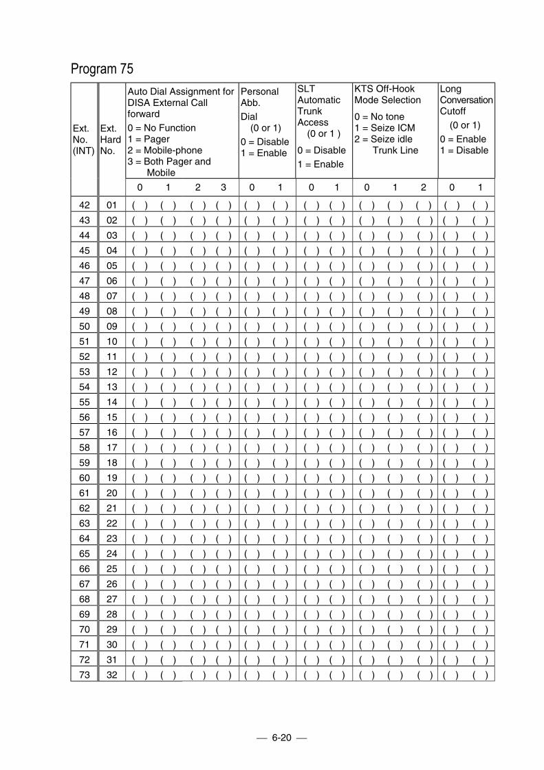
6-20
Program 75Auto Dial Assignment forDISA External Callforward0 = No Function1 = Pager2 = Mobile-phone3 = Both Pager and Mobile
PersonalAbb.Dial (0 or 1)0 = Disable1 = Enable
SLTAutomaticTrunkAccess (0 or 1 )
0 = Disable1 = Enable
KTS Off-HookMode Selection
0 = No tone1 = Seize ICM2 = Seize idle
Trunk Line
LongConversationCutoff (0 or 1)0 = Enable1 = Disable
Ext.No.(INT)
Ext.HardNo.
0 1 2 3 0 1 0 1 0 1 2 0 1
42 01 ( ) ( ) ( ) ( ) ( ) ( ) ( ) ( ) ( ) ( ) ( ) ( ) ( )
43 02 ( ) ( ) ( ) ( ) ( ) ( ) ( ) ( ) ( ) ( ) ( ) ( ) ( )
44 03 ( ) ( ) ( ) ( ) ( ) ( ) ( ) ( ) ( ) ( ) ( ) ( ) ( )
45 04 ( ) ( ) ( ) ( ) ( ) ( ) ( ) ( ) ( ) ( ) ( ) ( ) ( )
46 05 ( ) ( ) ( ) ( ) ( ) ( ) ( ) ( ) ( ) ( ) ( ) ( ) ( )
47 06 ( ) ( ) ( ) ( ) ( ) ( ) ( ) ( ) ( ) ( ) ( ) ( ) ( )
48 07 ( ) ( ) ( ) ( ) ( ) ( ) ( ) ( ) ( ) ( ) ( ) ( ) ( )
49 08 ( ) ( ) ( ) ( ) ( ) ( ) ( ) ( ) ( ) ( ) ( ) ( ) ( )
50 09 ( ) ( ) ( ) ( ) ( ) ( ) ( ) ( ) ( ) ( ) ( ) ( ) ( )
51 10 ( ) ( ) ( ) ( ) ( ) ( ) ( ) ( ) ( ) ( ) ( ) ( ) ( )
52 11 ( ) ( ) ( ) ( ) ( ) ( ) ( ) ( ) ( ) ( ) ( ) ( ) ( )
53 12 ( ) ( ) ( ) ( ) ( ) ( ) ( ) ( ) ( ) ( ) ( ) ( ) ( )
54 13 ( ) ( ) ( ) ( ) ( ) ( ) ( ) ( ) ( ) ( ) ( ) ( ) ( )
55 14 ( ) ( ) ( ) ( ) ( ) ( ) ( ) ( ) ( ) ( ) ( ) ( ) ( )
56 15 ( ) ( ) ( ) ( ) ( ) ( ) ( ) ( ) ( ) ( ) ( ) ( ) ( )
57 16 ( ) ( ) ( ) ( ) ( ) ( ) ( ) ( ) ( ) ( ) ( ) ( ) ( )
58 17 ( ) ( ) ( ) ( ) ( ) ( ) ( ) ( ) ( ) ( ) ( ) ( ) ( )
59 18 ( ) ( ) ( ) ( ) ( ) ( ) ( ) ( ) ( ) ( ) ( ) ( ) ( )
60 19 ( ) ( ) ( ) ( ) ( ) ( ) ( ) ( ) ( ) ( ) ( ) ( ) ( )
61 20 ( ) ( ) ( ) ( ) ( ) ( ) ( ) ( ) ( ) ( ) ( ) ( ) ( )
62 21 ( ) ( ) ( ) ( ) ( ) ( ) ( ) ( ) ( ) ( ) ( ) ( ) ( )
63 22 ( ) ( ) ( ) ( ) ( ) ( ) ( ) ( ) ( ) ( ) ( ) ( ) ( )
64 23 ( ) ( ) ( ) ( ) ( ) ( ) ( ) ( ) ( ) ( ) ( ) ( ) ( )
65 24 ( ) ( ) ( ) ( ) ( ) ( ) ( ) ( ) ( ) ( ) ( ) ( ) ( )
66 25 ( ) ( ) ( ) ( ) ( ) ( ) ( ) ( ) ( ) ( ) ( ) ( ) ( )
67 26 ( ) ( ) ( ) ( ) ( ) ( ) ( ) ( ) ( ) ( ) ( ) ( ) ( )
68 27 ( ) ( ) ( ) ( ) ( ) ( ) ( ) ( ) ( ) ( ) ( ) ( ) ( )
69 28 ( ) ( ) ( ) ( ) ( ) ( ) ( ) ( ) ( ) ( ) ( ) ( ) ( )
70 29 ( ) ( ) ( ) ( ) ( ) ( ) ( ) ( ) ( ) ( ) ( ) ( ) ( )
71 30 ( ) ( ) ( ) ( ) ( ) ( ) ( ) ( ) ( ) ( ) ( ) ( ) ( )
72 31 ( ) ( ) ( ) ( ) ( ) ( ) ( ) ( ) ( ) ( ) ( ) ( ) ( )
73 32 ( ) ( ) ( ) ( ) ( ) ( ) ( ) ( ) ( ) ( ) ( ) ( ) ( )
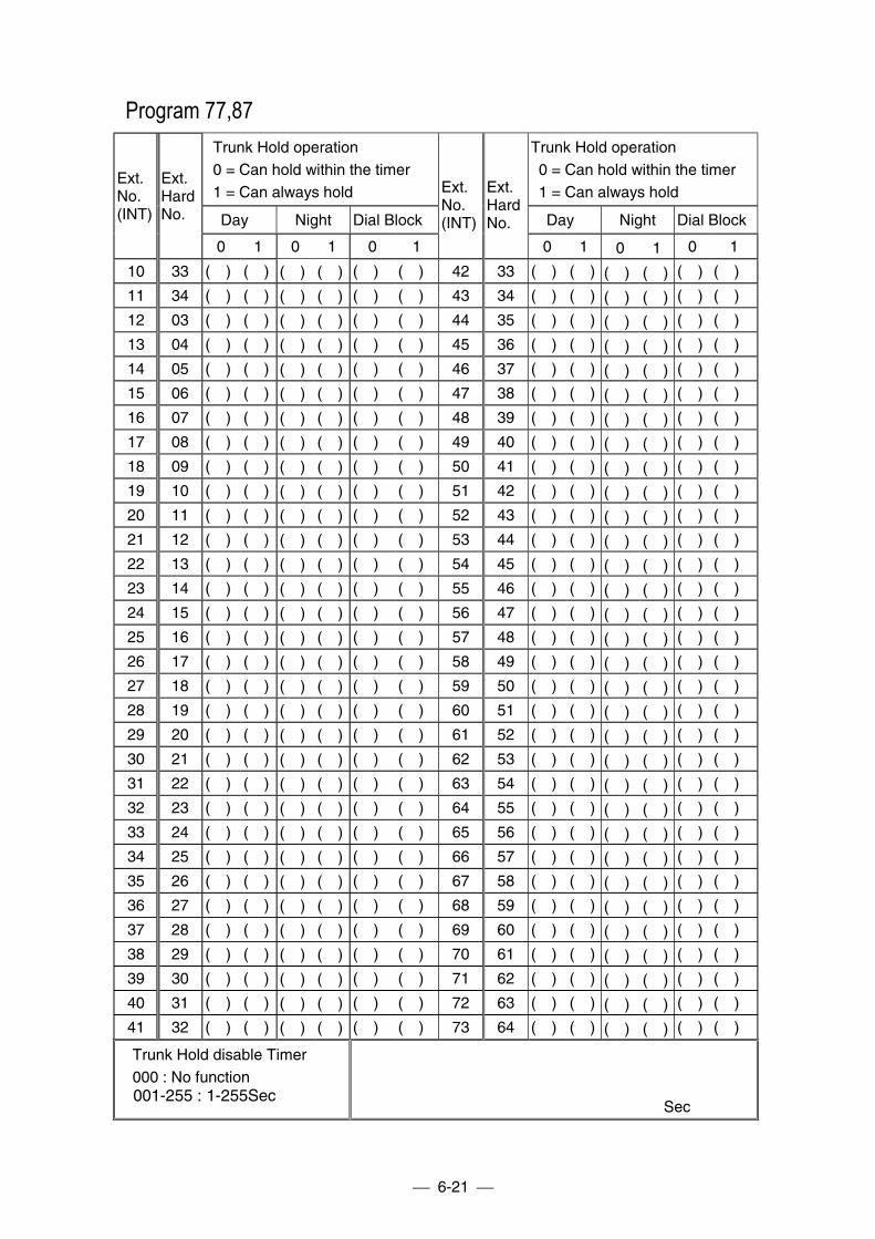
6-21
Program 77,87 Trunk Hold operation 0 = Can hold within the timer 1 = Can always hold
Trunk Hold operation 0 = Can hold within the timer 1 = Can always hold
Day Night Dial Block Day Night Dial Block
Ext.No.(INT)
Ext.HardNo.
0 1 0 1 0 1
Ext.No.(INT)
Ext.HardNo.
0 1 0 1 0 1
10 33 ( ) ( ) ( ) ( ) ( ) ( ) 42 33 ( ) ( ) ( ) ( ) ( ) ( )
11 34 ( ) ( ) ( ) ( ) ( ) ( ) 43 34 ( ) ( ) ( ) ( ) ( ) ( )
12 03 ( ) ( ) ( ) ( ) ( ) ( ) 44 35 ( ) ( ) ( ) ( ) ( ) ( )
13 04 ( ) ( ) ( ) ( ) ( ) ( ) 45 36 ( ) ( ) ( ) ( ) ( ) ( )
14 05 ( ) ( ) ( ) ( ) ( ) ( ) 46 37 ( ) ( ) ( ) ( ) ( ) ( )
15 06 ( ) ( ) ( ) ( ) ( ) ( ) 47 38 ( ) ( ) ( ) ( ) ( ) ( )
16 07 ( ) ( ) ( ) ( ) ( ) ( ) 48 39 ( ) ( ) ( ) ( ) ( ) ( )
17 08 ( ) ( ) ( ) ( ) ( ) ( ) 49 40 ( ) ( ) ( ) ( ) ( ) ( )
18 09 ( ) ( ) ( ) ( ) ( ) ( ) 50 41 ( ) ( ) ( ) ( ) ( ) ( )
19 10 ( ) ( ) ( ) ( ) ( ) ( ) 51 42 ( ) ( ) ( ) ( ) ( ) ( )
20 11 ( ) ( ) ( ) ( ) ( ) ( ) 52 43 ( ) ( ) ( ) ( ) ( ) ( )
21 12 ( ) ( ) ( ) ( ) ( ) ( ) 53 44 ( ) ( ) ( ) ( ) ( ) ( )
22 13 ( ) ( ) ( ) ( ) ( ) ( ) 54 45 ( ) ( ) ( ) ( ) ( ) ( )
23 14 ( ) ( ) ( ) ( ) ( ) ( ) 55 46 ( ) ( ) ( ) ( ) ( ) ( )
24 15 ( ) ( ) ( ) ( ) ( ) ( ) 56 47 ( ) ( ) ( ) ( ) ( ) ( )
25 16 ( ) ( ) ( ) ( ) ( ) ( ) 57 48 ( ) ( ) ( ) ( ) ( ) ( )
26 17 ( ) ( ) ( ) ( ) ( ) ( ) 58 49 ( ) ( ) ( ) ( ) ( ) ( )
27 18 ( ) ( ) ( ) ( ) ( ) ( ) 59 50 ( ) ( ) ( ) ( ) ( ) ( )
28 19 ( ) ( ) ( ) ( ) ( ) ( ) 60 51 ( ) ( ) ( ) ( ) ( ) ( )
29 20 ( ) ( ) ( ) ( ) ( ) ( ) 61 52 ( ) ( ) ( ) ( ) ( ) ( )
30 21 ( ) ( ) ( ) ( ) ( ) ( ) 62 53 ( ) ( ) ( ) ( ) ( ) ( )
31 22 ( ) ( ) ( ) ( ) ( ) ( ) 63 54 ( ) ( ) ( ) ( ) ( ) ( )
32 23 ( ) ( ) ( ) ( ) ( ) ( ) 64 55 ( ) ( ) ( ) ( ) ( ) ( )
33 24 ( ) ( ) ( ) ( ) ( ) ( ) 65 56 ( ) ( ) ( ) ( ) ( ) ( )
34 25 ( ) ( ) ( ) ( ) ( ) ( ) 66 57 ( ) ( ) ( ) ( ) ( ) ( )
35 26 ( ) ( ) ( ) ( ) ( ) ( ) 67 58 ( ) ( ) ( ) ( ) ( ) ( )
36 27 ( ) ( ) ( ) ( ) ( ) ( ) 68 59 ( ) ( ) ( ) ( ) ( ) ( )
37 28 ( ) ( ) ( ) ( ) ( ) ( ) 69 60 ( ) ( ) ( ) ( ) ( ) ( )
38 29 ( ) ( ) ( ) ( ) ( ) ( ) 70 61 ( ) ( ) ( ) ( ) ( ) ( )
39 30 ( ) ( ) ( ) ( ) ( ) ( ) 71 62 ( ) ( ) ( ) ( ) ( ) ( )
40 31 ( ) ( ) ( ) ( ) ( ) ( ) 72 63 ( ) ( ) ( ) ( ) ( ) ( )
41 32 ( ) ( ) ( ) ( ) ( ) ( ) 73 64 ( ) ( ) ( ) ( ) ( ) ( )
Trunk Hold disable Timer 000 : No function 001-255 : 1-255Sec
Sec
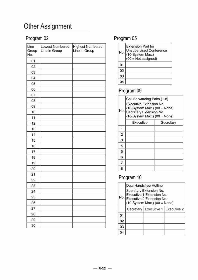
6-22
Other AssignmentProgram 02 Program 05LineGroupNo.
Lowest NumberedLine in Group
Highest NumberedLine in Group
01
02
03
04
05
06
07
08
09
10
11
12
13
14
15
16
17
18
19
20
21
22
23
24
25
26
27
28
29
30
No.
Extension Port forUnsupervised Conference(10-System Max.)(00 = Not assigned)
01
02
03
04
Program 09Call Forwarding Pairs (1-8)Executive Extension No.(10-System Max.) (00 = None)Secretary Extension No.(10-System Max.) (00 = None)
No.
Executive Secretary
1
2
3
4
5
6
7
8
Program 10Dual Handsfree HotlineSecretary Extension No.Executive 1 Extension No.Executive 2 Extension No.(10-System Max.) (00 = None)
No.
Secretary Executive 1 Executive 2
01
02
03
04
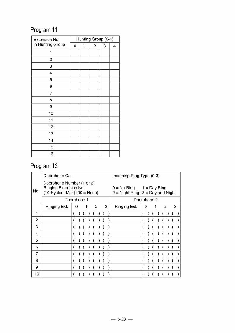
6-23
Program 11Hunting Group (0-4)Extension No.
in Hunting Group 0 1 2 3 4
1
2
3
4
5
6
7
8
9
10
11
12
13
14
15
16
Program 12Doorphone Call
Doorphone Number (1 or 2)Ringing Extension No.(10-System Max) (00 = None)
Incoming Ring Type (0-3)
0 = No Ring 1 = Day Ring2 = Night Ring 3 = Day and Night
Doorphone 1 Doorphone 2
No.
Ringing Ext. 0 1 2 3 Ringing Ext. 0 1 2 3
1 ( ) ( ) ( ) ( ) ( ) ( ) ( ) ( )
2 ( ) ( ) ( ) ( ) ( ) ( ) ( ) ( )
3 ( ) ( ) ( ) ( ) ( ) ( ) ( ) ( )
4 ( ) ( ) ( ) ( ) ( ) ( ) ( ) ( )
5 ( ) ( ) ( ) ( ) ( ) ( ) ( ) ( )
6 ( ) ( ) ( ) ( ) ( ) ( ) ( ) ( )
7 ( ) ( ) ( ) ( ) ( ) ( ) ( ) ( )
8 ( ) ( ) ( ) ( ) ( ) ( ) ( ) ( )
9 ( ) ( ) ( ) ( ) ( ) ( ) ( ) ( )
10 ( ) ( ) ( ) ( ) ( ) ( ) ( ) ( )
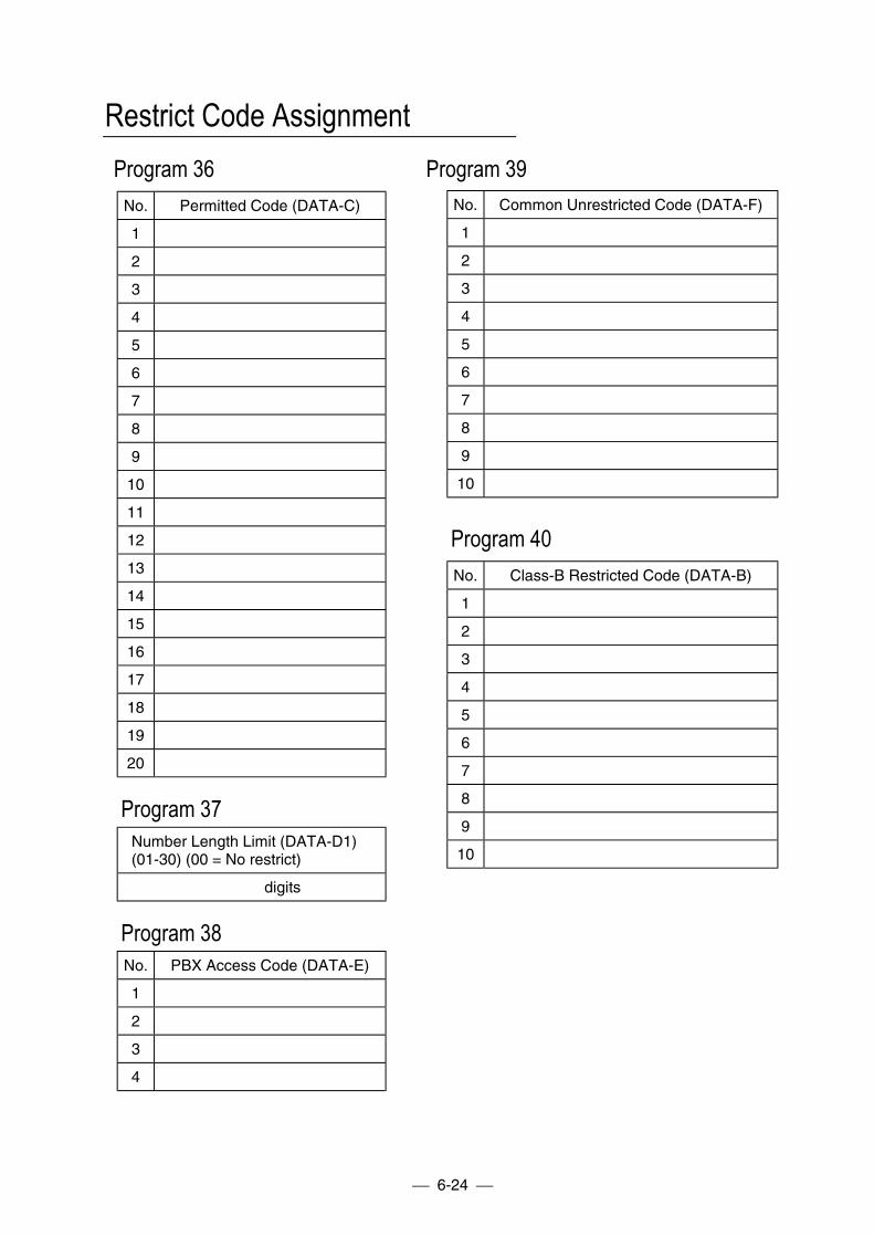
6-24
Restrict Code AssignmentProgram 36 Program 39
No. Permitted Code (DATA-C)
1
2
3
4
5
6
7
8
9
10
11
12
13
14
15
16
17
18
19
20
Program 37Number Length Limit (DATA-D1)(01-30) (00 = No restrict)
digits
Program 38No. PBX Access Code (DATA-E)
1
2
3
4
No. Common Unrestricted Code (DATA-F)
1
2
3
4
5
6
7
8
9
10
Program 40No. Class-B Restricted Code (DATA-B)
1
2
3
4
5
6
7
8
9
10
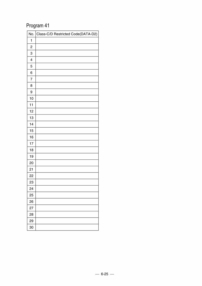
6-25
Program 41No. Class-C/D Restricted Code(DATA-D2)
1
2
3
4
5
6
7
8
9
10
11
12
13
14
15
16
17
18
19
20
21
22
23
24
25
26
27
28
29
30
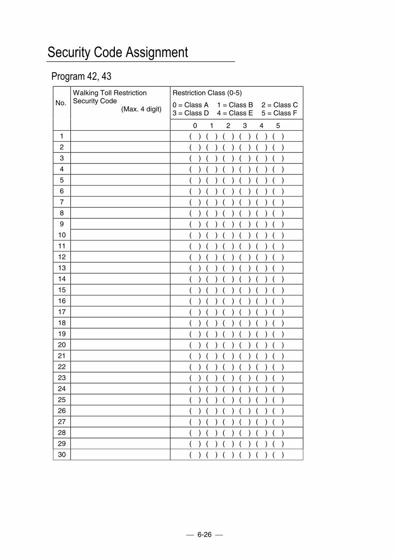
6-26
Security Code AssignmentProgram 42, 43
No.Walking Toll RestrictionSecurity Code
(Max. 4 digit)
Restriction Class (0-5)
0 = Class A 1 = Class B 2 = Class C3 = Class D 4 = Class E 5 = Class F
0 1 2 3 4 5
1 ( ) ( ) ( ) ( ) ( ) ( )
2 ( ) ( ) ( ) ( ) ( ) ( )
3 ( ) ( ) ( ) ( ) ( ) ( )
4 ( ) ( ) ( ) ( ) ( ) ( )
5 ( ) ( ) ( ) ( ) ( ) ( )
6 ( ) ( ) ( ) ( ) ( ) ( )
7 ( ) ( ) ( ) ( ) ( ) ( )
8 ( ) ( ) ( ) ( ) ( ) ( )
9 ( ) ( ) ( ) ( ) ( ) ( )
10 ( ) ( ) ( ) ( ) ( ) ( )
11 ( ) ( ) ( ) ( ) ( ) ( )
12 ( ) ( ) ( ) ( ) ( ) ( )
13 ( ) ( ) ( ) ( ) ( ) ( )
14 ( ) ( ) ( ) ( ) ( ) ( )
15 ( ) ( ) ( ) ( ) ( ) ( )
16 ( ) ( ) ( ) ( ) ( ) ( )
17 ( ) ( ) ( ) ( ) ( ) ( )
18 ( ) ( ) ( ) ( ) ( ) ( )
19 ( ) ( ) ( ) ( ) ( ) ( )
20 ( ) ( ) ( ) ( ) ( ) ( )
21 ( ) ( ) ( ) ( ) ( ) ( )
22 ( ) ( ) ( ) ( ) ( ) ( )
23 ( ) ( ) ( ) ( ) ( ) ( )
24 ( ) ( ) ( ) ( ) ( ) ( )
25 ( ) ( ) ( ) ( ) ( ) ( )
26 ( ) ( ) ( ) ( ) ( ) ( )
27 ( ) ( ) ( ) ( ) ( ) ( )
28 ( ) ( ) ( ) ( ) ( ) ( )
29 ( ) ( ) ( ) ( ) ( ) ( )
30 ( ) ( ) ( ) ( ) ( ) ( )
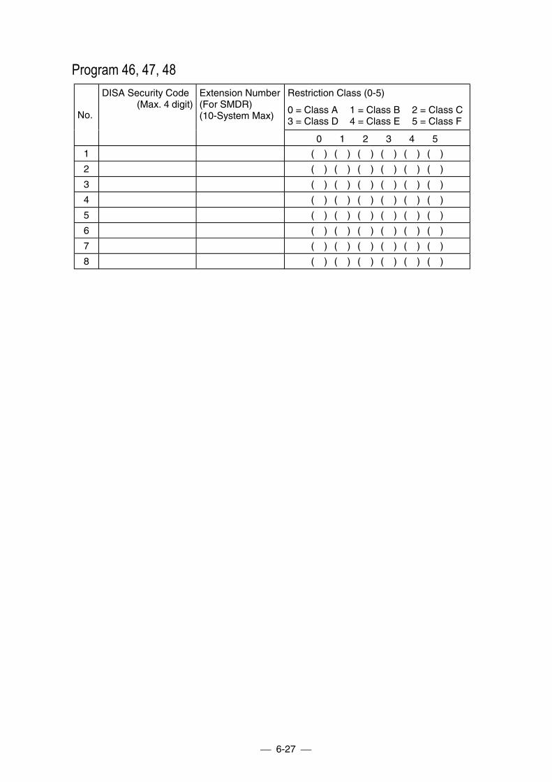
6-27
Program 46, 47, 48Restriction Class (0-5)
0 = Class A 1 = Class B 2 = Class C3 = Class D 4 = Class E 5 = Class F
No.
DISA Security Code(Max. 4 digit)
Extension Number(For SMDR)(10-System Max)
0 1 2 3 4 5
1 ( ) ( ) ( ) ( ) ( ) ( )
2 ( ) ( ) ( ) ( ) ( ) ( )
3 ( ) ( ) ( ) ( ) ( ) ( )
4 ( ) ( ) ( ) ( ) ( ) ( )
5 ( ) ( ) ( ) ( ) ( ) ( )
6 ( ) ( ) ( ) ( ) ( ) ( )
7 ( ) ( ) ( ) ( ) ( ) ( )
8 ( ) ( ) ( ) ( ) ( ) ( )
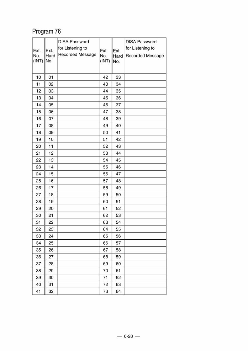
6-28
Program 76
Ext.No.(INT)
Ext.HardNo.
DISA Passwordfor Listening toRecorded Message
Ext.No.(INT)
Ext.HardNo.
DISA Passwordfor Listening to
Recorded Message
10 01 42 33
11 02 43 34
12 03 44 35
13 04 45 36
14 05 46 37
15 06 47 38
16 07 48 39
17 08 49 40
18 09 50 41
19 10 51 42
20 11 52 43
21 12 53 44
22 13 54 45
23 14 55 46
24 15 56 47
25 16 57 48
26 17 58 49
27 18 59 50
28 19 60 51
29 20 61 52
30 21 62 53
31 22 63 54
32 23 64 55
33 24 65 56
34 25 66 57
35 26 67 58
36 27 68 59
37 28 69 60
38 29 70 61
39 30 71 62
40 31 72 63
41 32 73 64
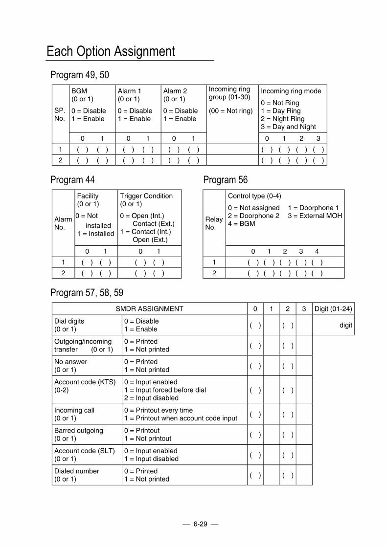
6-29
Each Option AssignmentProgram 49, 50
BGM(0 or 1)
0 = Disable1 = Enable
Alarm 1(0 or 1)
0 = Disable1 = Enable
Alarm 2(0 or 1)
0 = Disable1 = Enable
Incoming ring mode
0 = Not Ring1 = Day Ring2 = Night Ring3 = Day and Night
SP.No.
0 1 0 1 0 1
Incoming ringgroup (01-30)
(00 = Not ring)
0 1 2 3
1 ( ) ( ) ( ) ( ) ( ) ( ) ( ) ( ) ( ) ( )
2 ( ) ( ) ( ) ( ) ( ) ( ) ( ) ( ) ( ) ( )
Program 44 Program 56Facility(0 or 1)
0 = Not installed1 = Installed
Trigger Condition(0 or 1)
0 = Open (Int.)Contact (Ext.)
1 = Contact (Int.)Open (Ext.)
Control type (0-4)
0 = Not assigned 1 = Doorphone 12 = Doorphone 2 3 = External MOH4 = BGM
AlarmNo.
0 1 0 1
RelayNo.
0 1 2 3 4
1 ( ) ( ) ( ) ( ) 1 ( ) ( ) ( ) ( ) ( )
2 ( ) ( ) ( ) ( ) 2 ( ) ( ) ( ) ( ) ( )
Program 57, 58, 59SMDR ASSIGNMENT 0 1 2 3 Digit (01-24)
Dial digits(0 or 1)
0 = Disable1 = Enable
( ) ( ) digit
Outgoing/incomingtransfer (0 or 1)
0 = Printed1 = Not printed
( ) ( )
No answer(0 or 1)
0 = Printed1 = Not printed
( ) ( )
Account code (KTS)(0-2)
0 = Input enabled1 = Input forced before dial2 = Input disabled
( ) ( )
Incoming call(0 or 1)
0 = Printout every time1 = Printout when account code input
( ) ( )
Barred outgoing(0 or 1)
0 = Printout1 = Not printout
( ) ( )
Account code (SLT)(0 or 1)
0 = Input enabled1 = Input disabled
( ) ( )
Dialed number(0 or 1)
0 = Printed1 = Not printed
( ) ( )
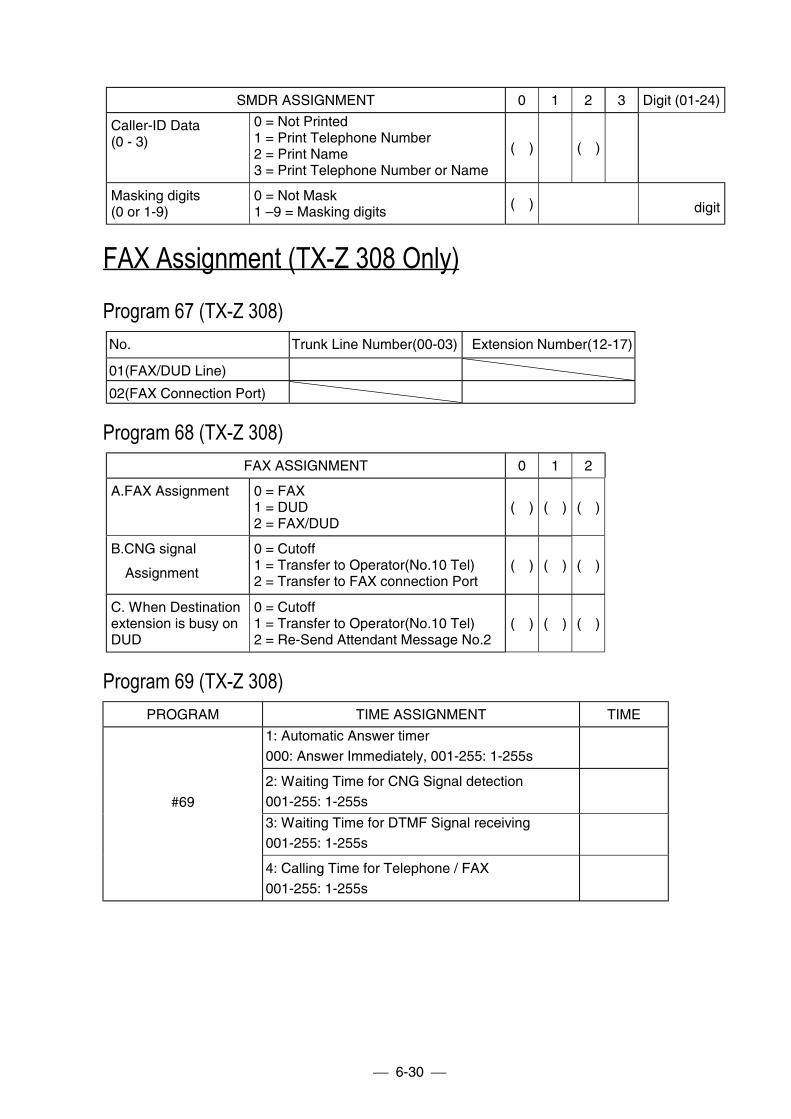
6-30
SMDR ASSIGNMENT 0 1 2 3 Digit (01-24)
Caller-ID Data(0 - 3)
0 = Not Printed1 = Print Telephone Number2 = Print Name3 = Print Telephone Number or Name
( ) ( )
Masking digits(0 or 1-9)
0 = Not Mask1 –9 = Masking digits
( ) digit
FAX Assignment (TX-Z 308 Only)Program 67 (TX-Z 308)No. Trunk Line Number(00-03) Extension Number(12-17)
01(FAX/DUD Line)
02(FAX Connection Port)
Program 68 (TX-Z 308)FAX ASSIGNMENT 0 1 2
A.FAX Assignment 0 = FAX1 = DUD2 = FAX/DUD
( ) ( ) ( )
B.CNG signal
Assignment
0 = Cutoff1 = Transfer to Operator(No.10 Tel)2 = Transfer to FAX connection Port
( ) ( ) ( )
C. When Destinationextension is busy onDUD
0 = Cutoff1 = Transfer to Operator(No.10 Tel)2 = Re-Send Attendant Message No.2
( ) ( ) ( )
Program 69 (TX-Z 308)PROGRAM TIME ASSIGNMENT TIME
1: Automatic Answer timer000: Answer Immediately, 001-255: 1-255s
2: Waiting Time for CNG Signal detection001-255: 1-255s
3: Waiting Time for DTMF Signal receiving001-255: 1-255s
#69
4: Calling Time for Telephone / FAX001-255: 1-255s
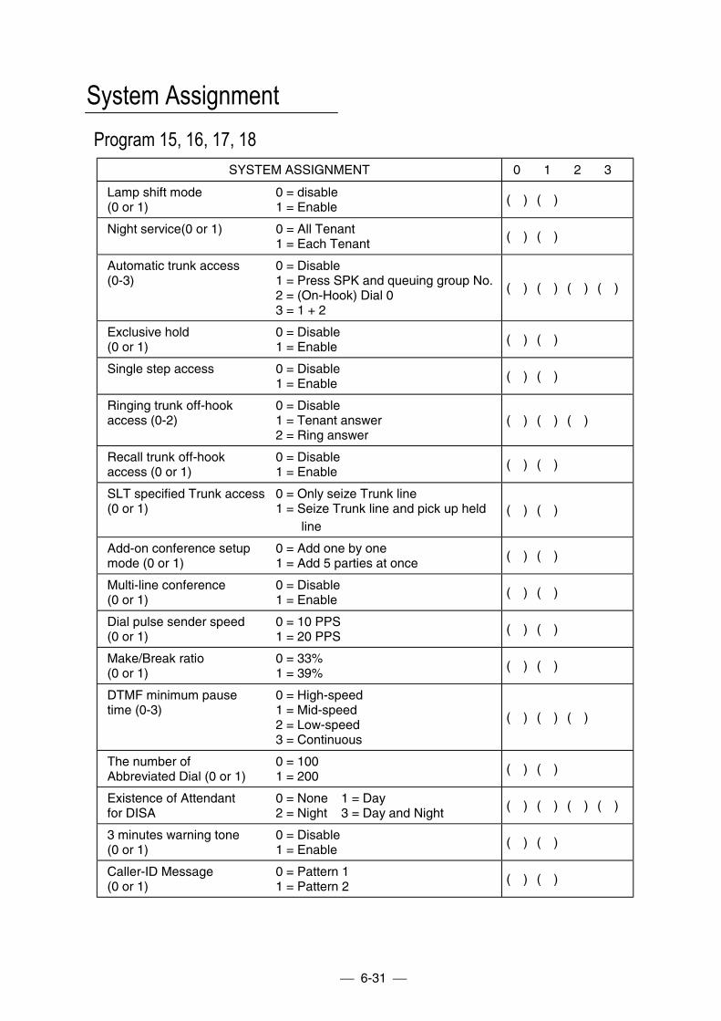
6-31
System AssignmentProgram 15, 16, 17, 18
SYSTEM ASSIGNMENT 0 1 2 3
Lamp shift mode(0 or 1)
0 = disable1 = Enable
( ) ( )
Night service(0 or 1) 0 = All Tenant1 = Each Tenant
( ) ( )
Automatic trunk access(0-3)
0 = Disable1 = Press SPK and queuing group No.2 = (On-Hook) Dial 03 = 1 + 2
( ) ( ) ( ) ( )
Exclusive hold(0 or 1)
0 = Disable1 = Enable
( ) ( )
Single step access 0 = Disable1 = Enable
( ) ( )
Ringing trunk off-hookaccess (0-2)
0 = Disable1 = Tenant answer2 = Ring answer
( ) ( ) ( )
Recall trunk off-hookaccess (0 or 1)
0 = Disable1 = Enable
( ) ( )
SLT specified Trunk access(0 or 1)
0 = Only seize Trunk line1 = Seize Trunk line and pick up held line
( ) ( )
Add-on conference setupmode (0 or 1)
0 = Add one by one1 = Add 5 parties at once
( ) ( )
Multi-line conference(0 or 1)
0 = Disable1 = Enable
( ) ( )
Dial pulse sender speed(0 or 1)
0 = 10 PPS1 = 20 PPS
( ) ( )
Make/Break ratio(0 or 1)
0 = 33%1 = 39%
( ) ( )
DTMF minimum pausetime (0-3)
0 = High-speed1 = Mid-speed2 = Low-speed3 = Continuous
( ) ( ) ( )
The number ofAbbreviated Dial (0 or 1)
0 = 1001 = 200
( ) ( )
Existence of Attendantfor DISA
0 = None 1 = Day2 = Night 3 = Day and Night
( ) ( ) ( ) ( )
3 minutes warning tone(0 or 1)
0 = Disable1 = Enable
( ) ( )
Caller-ID Message(0 or 1)
0 = Pattern 11 = Pattern 2
( ) ( )
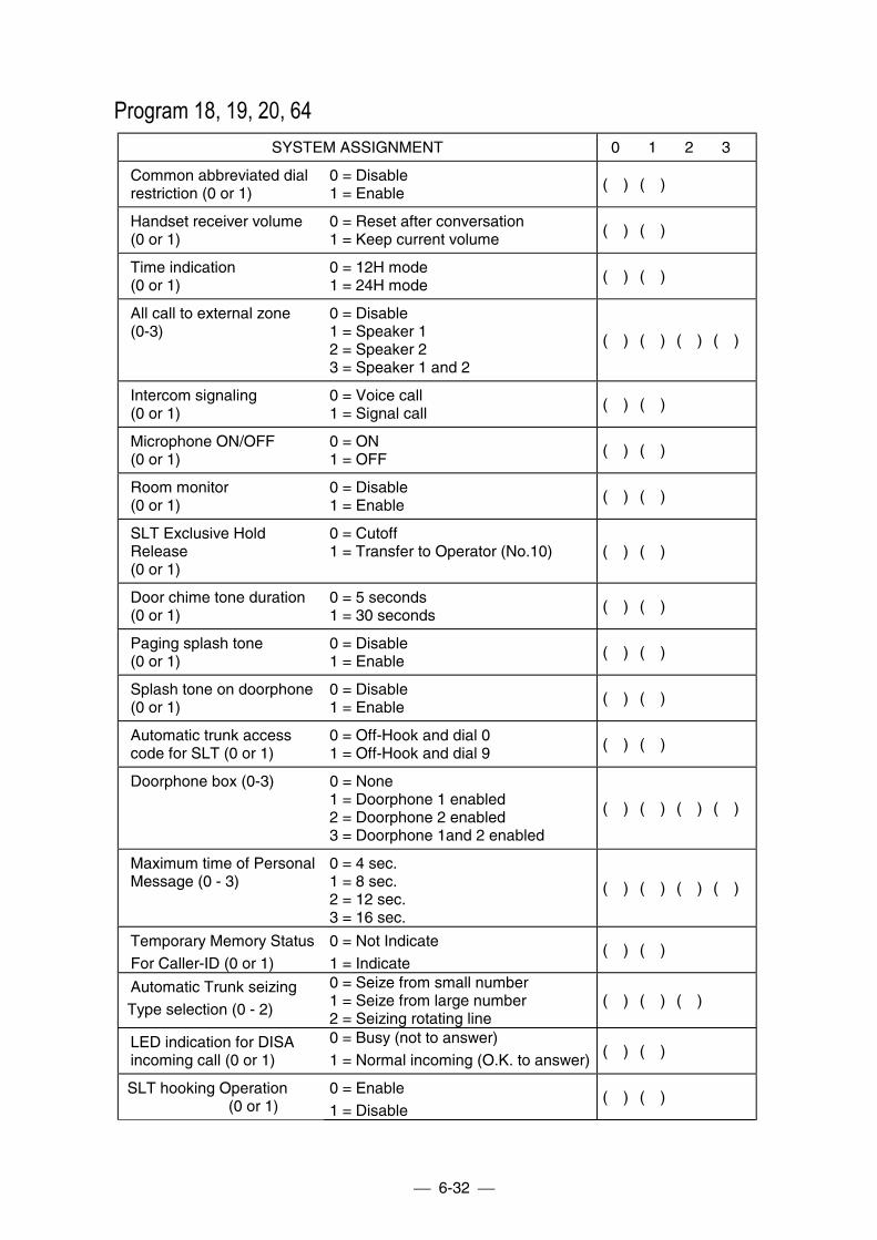
6-32
Program 18, 19, 20, 64SYSTEM ASSIGNMENT 0 1 2 3
Common abbreviated dialrestriction (0 or 1)
0 = Disable1 = Enable
( ) ( )
Handset receiver volume(0 or 1)
0 = Reset after conversation1 = Keep current volume
( ) ( )
Time indication(0 or 1)
0 = 12H mode1 = 24H mode
( ) ( )
All call to external zone(0-3)
0 = Disable1 = Speaker 12 = Speaker 23 = Speaker 1 and 2
( ) ( ) ( ) ( )
Intercom signaling(0 or 1)
0 = Voice call1 = Signal call
( ) ( )
Microphone ON/OFF(0 or 1)
0 = ON1 = OFF
( ) ( )
Room monitor(0 or 1)
0 = Disable1 = Enable
( ) ( )
SLT Exclusive HoldRelease(0 or 1)
0 = Cutoff1 = Transfer to Operator (No.10) ( ) ( )
Door chime tone duration(0 or 1)
0 = 5 seconds1 = 30 seconds
( ) ( )
Paging splash tone(0 or 1)
0 = Disable1 = Enable
( ) ( )
Splash tone on doorphone(0 or 1)
0 = Disable1 = Enable
( ) ( )
Automatic trunk accesscode for SLT (0 or 1)
0 = Off-Hook and dial 01 = Off-Hook and dial 9
( ) ( )
Doorphone box (0-3) 0 = None1 = Doorphone 1 enabled2 = Doorphone 2 enabled3 = Doorphone 1and 2 enabled
( ) ( ) ( ) ( )
Maximum time of PersonalMessage (0 - 3)
0 = 4 sec.1 = 8 sec.2 = 12 sec.3 = 16 sec.
( ) ( ) ( ) ( )
Temporary Memory StatusFor Caller-ID (0 or 1)
0 = Not Indicate1 = Indicate
( ) ( )
Automatic Trunk seizingType selection (0 - 2)
0 = Seize from small number1 = Seize from large number2 = Seizing rotating line
( ) ( ) ( )
LED indication for DISAincoming call (0 or 1)
0 = Busy (not to answer)1 = Normal incoming (O.K. to answer)
( ) ( )
SLT hooking Operation (0 or 1)
0 = Enable1 = Disable
( ) ( )
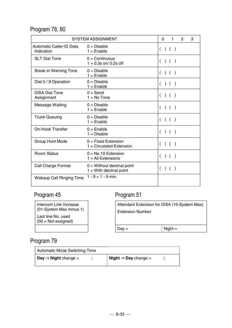
6-33
Program 78, 80SYSTEM ASSIGNMENT 0 1 2 3
Automatic Caller-ID DataIndication
0 = Disable1 = Enable
( ) ( )
SLT Dial Tone 0 = Continuous1 = 0.3s on/ 0.2s off
( ) ( )
Break In Warning Tone 0 = Disable1 = Enable
( ) ( )
Dial 0 / 9 Operation 0 = Disable1 = Enable
( ) ( )
DISA Dial ToneAssignment
0 = Send1 = No Tone
( ) ( )
Message Waiting 0 = Disable1 = Enable
( ) ( )
Trunk Queuing 0 = Disable1 = Enable
( ) ( )
On-Hook Transfer 0 = Enable1 = Disable
( ) ( )
Group Hunt Mode 0 = Fixed Extension1 = Circulated Extension
( ) ( )
Room Status
0 = No.10 Extension1 = All Extensions
( ) ( )
Call Charge Format 0 = Without decimal point1 = With decimal point
( ) ( )
Wakeup Call Ringing Time 1 - 9 = 1 - 9 min.
Program 45 Program 51Intercom Link Increase(01-System Max minus 1)
Last line No. used(00 = Not assigned)
Attendant Extension for DISA (10-System Max)
Extension Number
Day = Night =
Program 79Automatic Mode Switching Time
Day !!!! Night change = : Night !!!! Day change = :
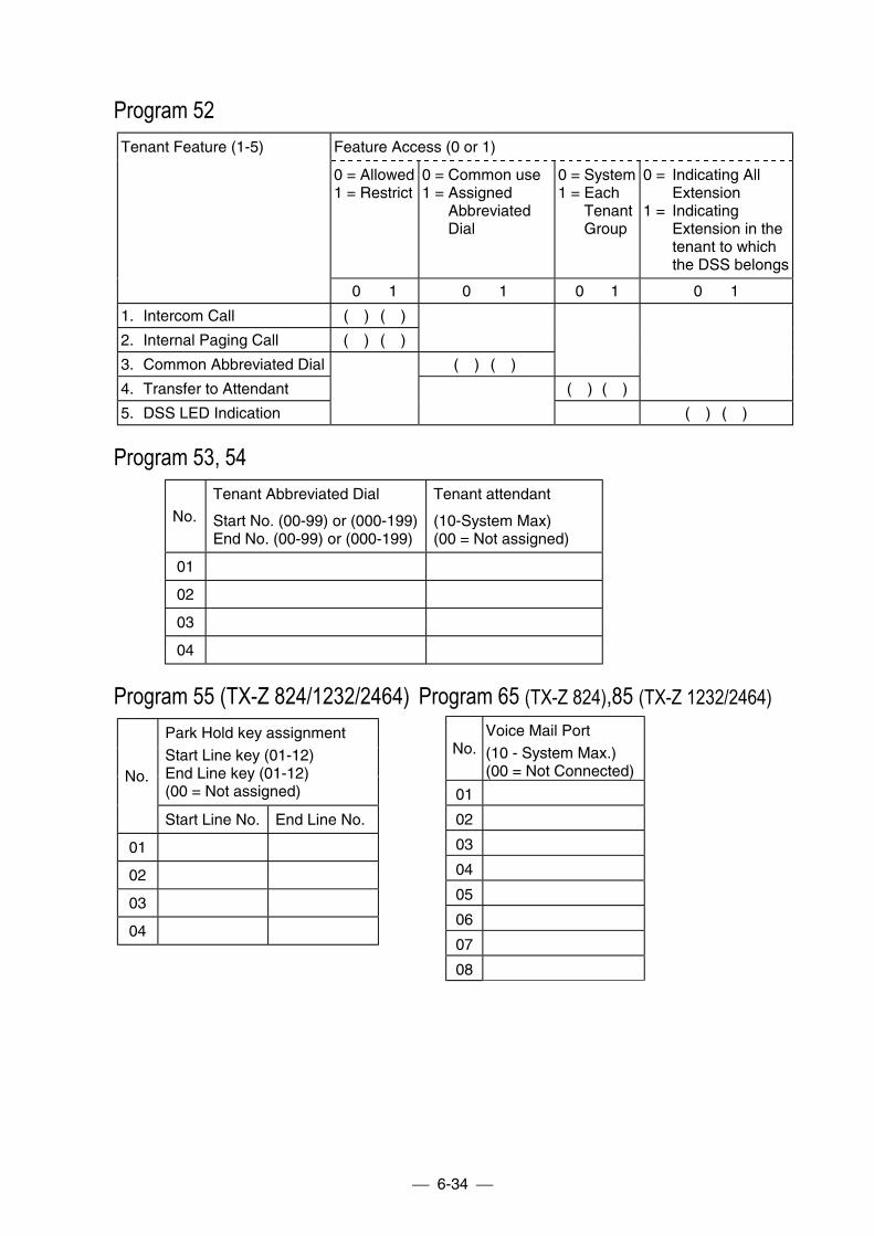
6-34
Program 52Feature Access (0 or 1)
0 = Allowed1 = Restrict
0 = Common use1 = Assigned
AbbreviatedDial
0 = System1 = Each
TenantGroup
0 = Indicating AllExtension
1 = IndicatingExtension in thetenant to whichthe DSS belongs
Tenant Feature (1-5)
0 1 0 1 0 1 0 1
1. Intercom Call ( ) ( )
2. Internal Paging Call ( ) ( )
3. Common Abbreviated Dial ( ) ( )
4. Transfer to Attendant ( ) ( )
5. DSS LED Indication ( ) ( )
Program 53, 54
No.Tenant Abbreviated Dial
Start No. (00-99) or (000-199)End No. (00-99) or (000-199)
Tenant attendant
(10-System Max)(00 = Not assigned)
01
02
03
04
Program 55 (TX-Z 824/1232/2464) Program 65 (TX-Z 824),85 (TX-Z 1232/2464)Park Hold key assignmentStart Line key (01-12)End Line key (01-12)(00 = Not assigned)
No.
Start Line No. End Line No.
01
02
03
04
No.Voice Mail Port(10 - System Max.)(00 = Not Connected)
01
02
03
04
05
06
07
08
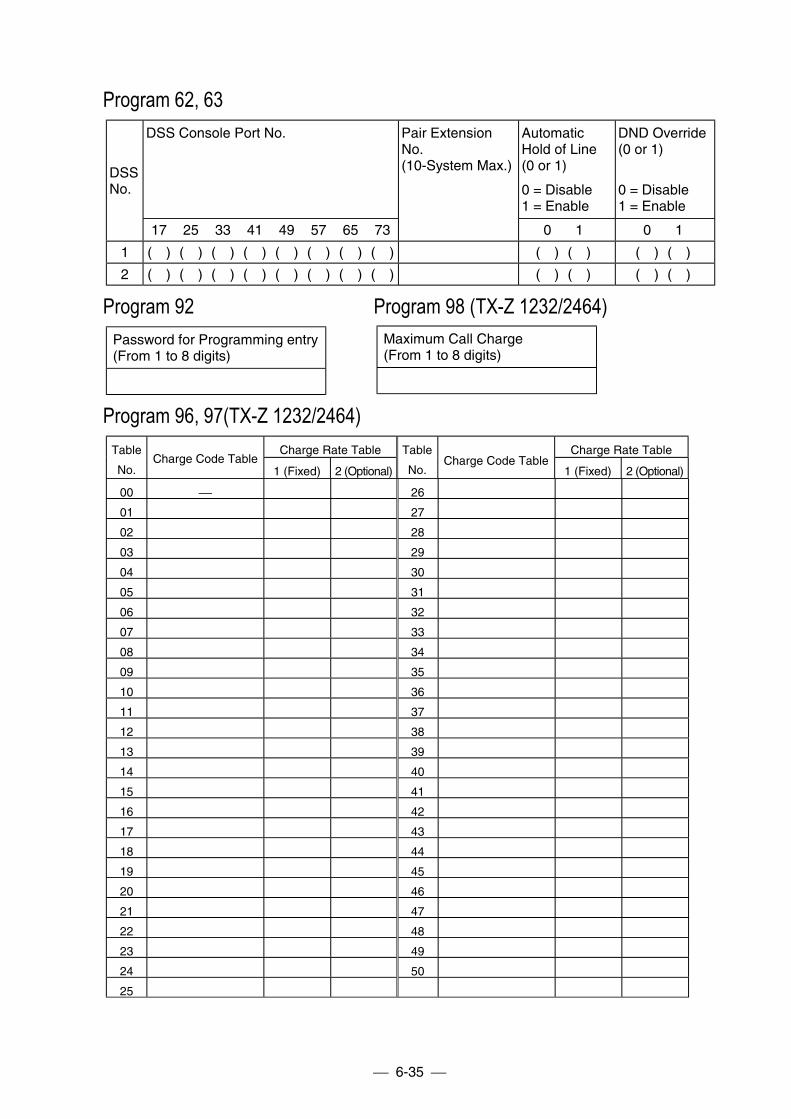
6-35
Program 62, 63DSS Console Port No. Automatic
Hold of Line(0 or 1)
0 = Disable1 = Enable
DND Override(0 or 1)
0 = Disable1 = Enable
DSSNo.
17 25 33 41 49 57 65 73
Pair ExtensionNo.(10-System Max.)
0 1 0 1
1 ( ) ( ) ( ) ( ) ( ) ( ) ( ) ( ) ( ) ( ) ( ) ( )
2 ( ) ( ) ( ) ( ) ( ) ( ) ( ) ( ) ( ) ( ) ( ) ( )
Program 92 Program 98 (TX-Z 1232/2464)Password for Programming entry(From 1 to 8 digits)
Program 96, 97(TX-Z 1232/2464)Charge Rate Table Charge Rate TableTable
No.Charge Code Table
1 (Fixed) 2 (Optional)
Table
No.Charge Code Table
1 (Fixed) 2 (Optional)
00 26
01 27
02 28
03 29
04 30
05 31
06 32
07 33
08 34
09 35
10 36
11 37
12 38
13 39
14 40
15 41
16 42
17 43
18 44
19 45
20 46
21 47
22 48
23 49
24 50
25
Maximum Call Charge(From 1 to 8 digits)
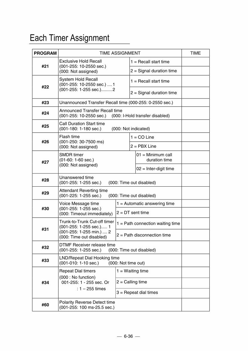
6-36
Each Timer AssignmentPROGRAM TIME ASSIGNMENT TIME
1 = Recall start time#21
Exclusive Hold Recall(001-255: 10-2550 sec.)(000: Not assigned) 2 = Signal duration time
1 = Recall start time#22
System Hold Recall(001-255: 10-2550 sec.) ....1(001-255: 1-255 sec.).........2
2 = Signal duration time
#23 Unannounced Transfer Recall time (000-255: 0-2550 sec.)
#24 Announced Transfer Recall time(001-255: 10-2550 sec.) (000: I-Hold transfer disabled)
#25 Call Duration Start time(001-180: 1-180 sec.) (000: Not indicated)
1 = CO Line#26
Flash time(001-250: 30-7500 ms)(000: Not assigned) 2 = PBX Line
01 = Minimum callduration time#27
SMDR timer(01-60: 1-60 sec.)(000: Not assigned)
02 = Inter-digit time
#28 Unanswered time(001-255: 1-255 sec.) (000: Time out disabled)
#29 Attendant Reverting time(001-225: 1-255 sec.) (000: Time out disabled)
1 = Automatic answering time#30
Voice Message time(001-255: 1-255 sec.)(000: Timeout immediately) 2 = DT sent time
1 = Path connection waiting time#31
Trunk-to-Trunk Cut-off timer(001-255: 1-255 sec.)..... 1(001-255: 1-255 min.) .... 2(000: Time out disabled) 2 = Path disconnection time
#32 DTMF Receiver release time(001-255: 1-255 sec.) (000: Time out disabled)
#33 LND/Repeat Dial Hooking time(001-010: 1-10 sec.) (000: Not time out)
1 = Waiting time
2 = Calling time#34
Repeat Dial timers(000 : No function) 001-255: 1 - 255 sec. Or : 1 – 255 times
3 = Repeat dial times
#60 Polarity Reverse Detect time(001-255: 100 ms-25.5 sec.)
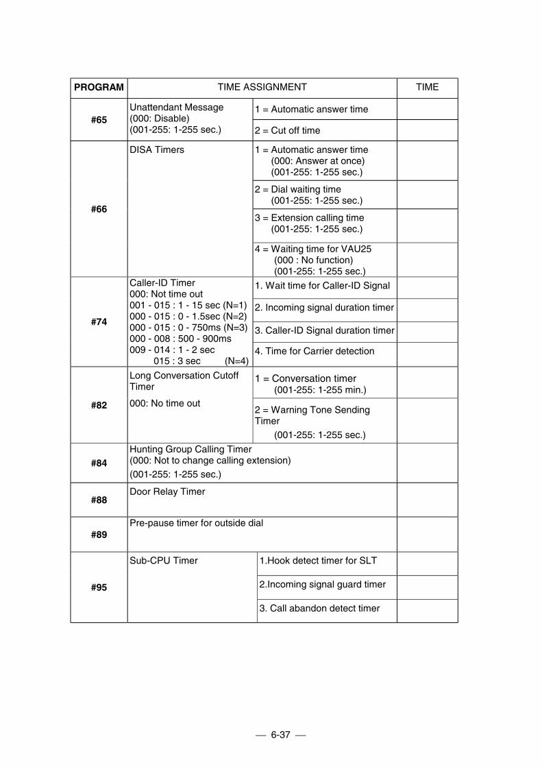
6-37
PROGRAM TIME ASSIGNMENT TIME
1 = Automatic answer time#65
Unattendant Message(000: Disable)(001-255: 1-255 sec.) 2 = Cut off time
1 = Automatic answer time(000: Answer at once)(001-255: 1-255 sec.)
2 = Dial waiting time(001-255: 1-255 sec.)
3 = Extension calling time(001-255: 1-255 sec.)
#66
DISA Timers
4 = Waiting time for VAU25 (000 : No function) (001-255: 1-255 sec.)
1. Wait time for Caller-ID Signal
2. Incoming signal duration timer
3. Caller-ID Signal duration timer#74
Caller-ID Timer000: Not time out001 - 015 : 1 - 15 sec (N=1)000 - 015 : 0 - 1.5sec (N=2)000 - 015 : 0 - 750ms (N=3)000 - 008 : 500 - 900ms009 - 014 : 1 - 2 sec 015 : 3 sec (N=4)
4. Time for Carrier detection
1 = Conversation timer (001-255: 1-255 min.)
#82
Long Conversation CutoffTimer
000: No time out2 = Warning Tone SendingTimer (001-255: 1-255 sec.)
#84Hunting Group Calling Timer(000: Not to change calling extension)(001-255: 1-255 sec.)
#88Door Relay Timer
#89Pre-pause timer for outside dial
1.Hook detect timer for SLT
2.Incoming signal guard timer#95
Sub-CPU Timer
3. Call abandon detect timer
PART 7
OPTIONAL ITEMS
PART 7-1
OPTIONAL ITEMFOR TX-Z 308/824/1232/2464
(CALLER-ID UNIT)
Table of Contents
General Description ............................................................................................................7-1-1
Required Items & Capacity .................................................................................................7-1-1
Installation of 3CIDU-A1 Unit (TX-Z 308) ...........................................................................7-1-2
Installing the Caller-ID Adaptor (TX-Z 824/1232/2464)......................................................7-1-5
Installing the SMCID PBA (TX-Z 824/1232/2464)..............................................................7-1-8
Display Indication for Caller-ID Information......................................................................7-1-11
Caller-ID Table..................................................................................................................7-1-17
Temporary Memory...........................................................................................................7-1-30
SMDR Printout ..................................................................................................................7-1-33
Feature Access Keys ........................................................................................................7-1-33
List of Display Information ................................................................................................7-1-35
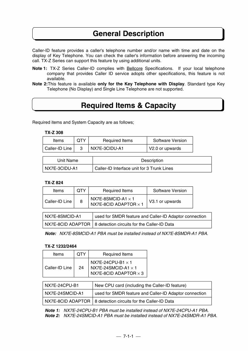
7-1-1
General Description
Caller-ID feature provides a caller's telephone number and/or name with time and date on thedisplay of Key Telephone. You can check the caller's information before answering the incomingcall. TX-Z Series can support this feature by using additional units.
Note 1: TX-Z Series Caller-ID complies with Bellcore Specifications. If your local telephonecompany that provides Caller ID service adopts other specifications, this feature is notavailable.
Note 2:This feature is available only for the Key Telephone with Display. Standard type KeyTelephone (No Display) and Single Line Telephone are not supported.
Required Items & Capacity
Required items and System Capacity are as follows;
TX-Z 308
Items QTY Required Items Software Version
Caller-ID Line 3 NX7E-3CIDU-A1 V2.0 or upwards
Unit Name Description
NX7E-3CIDU-A1 Caller-ID Interface unit for 3 Trunk Lines
TX-Z 824
Items QTY Required Items Software Version
Caller-ID Line 8NX7E-8SMCID-A1 × 1NX7E-8CID ADAPTOR × 1
V3.1 or upwards
NX7E-8SMCID-A1 used for SMDR feature and Caller-ID Adaptor connection
NX7E-8CID ADAPTOR 8 detection circuits for the Caller-ID Data
Note: NX7E-8SMCID-A1 PBA must be installed instead of NX7E-8SMDR-A1 PBA.
TX-Z 1232/2464
Items QTY Required Items
Caller-ID Line 24NX7E-24CPU-B1 × 1NX7E-24SMCID-A1 × 1NX7E-8CID ADAPTOR × 3
NX7E-24CPU-B1 New CPU card (including the Caller-ID feature)
NX7E-24SMCID-A1 used for SMDR feature and Caller-ID Adaptor connection
NX7E-8CID ADAPTOR 8 detection circuits for the Caller-ID Data
Note 1: NX7E-24CPU-B1 PBA must be installed instead of NX7E-24CPU-A1 PBA.Note 2: NX7E-24SMCID-A1 PBA must be installed instead of NX7E-24SMDR-A1 PBA.
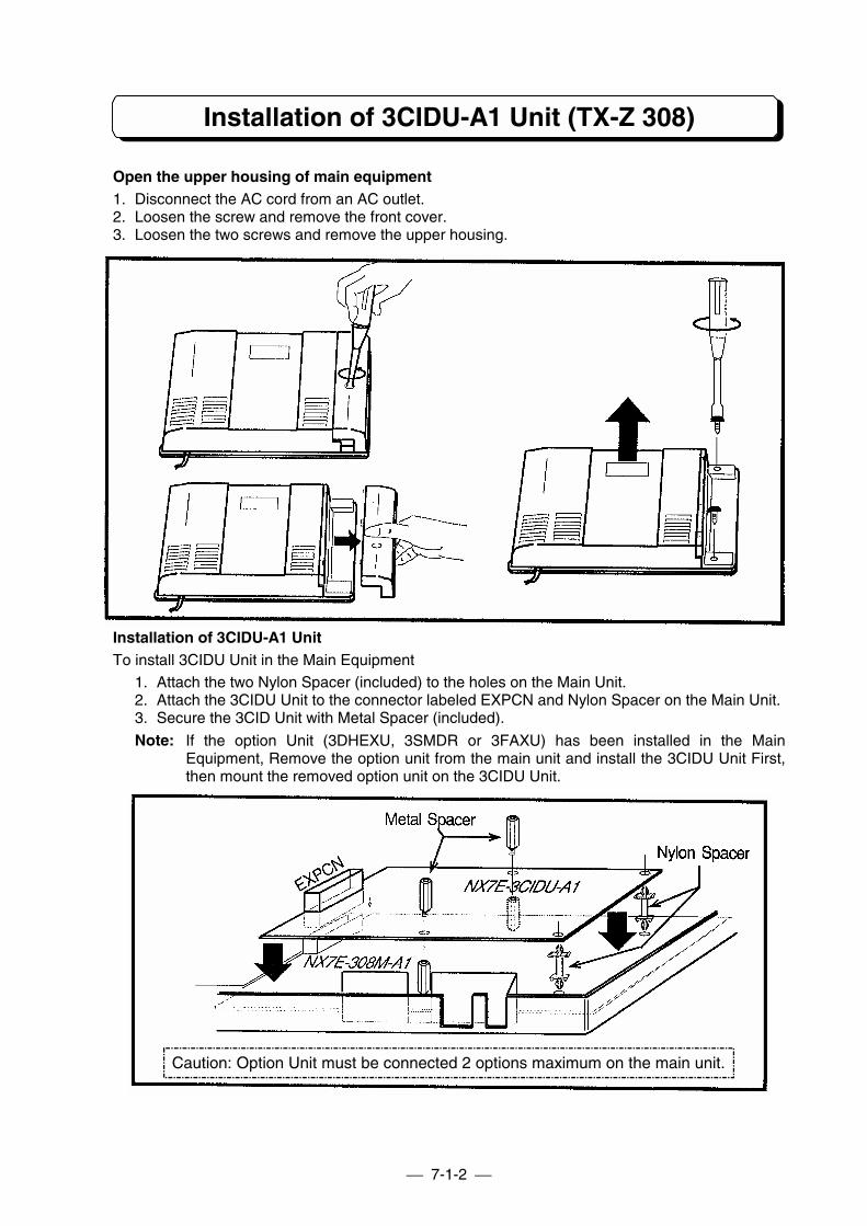
7-1-2
Installation of 3CIDU-A1 Unit (TX-Z 308)
Open the upper housing of main equipment1. Disconnect the AC cord from an AC outlet.2. Loosen the screw and remove the front cover.3. Loosen the two screws and remove the upper housing.
Installation of 3CIDU-A1 UnitTo install 3CIDU Unit in the Main Equipment
1. Attach the two Nylon Spacer (included) to the holes on the Main Unit.2. Attach the 3CIDU Unit to the connector labeled EXPCN and Nylon Spacer on the Main Unit.3. Secure the 3CID Unit with Metal Spacer (included).
Note: If the option Unit (3DHEXU, 3SMDR or 3FAXU) has been installed in the MainEquipment, Remove the option unit from the main unit and install the 3CIDU Unit First,then mount the removed option unit on the 3CIDU Unit.
Caution: Option Unit must be connected 2 options maximum on the main unit.
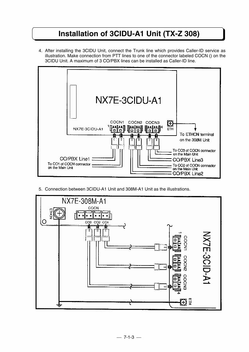
7-1-3
Installation of 3CIDU-A1 Unit (TX-Z 308)
4. After installing the 3CIDU Unit, connect the Trunk line which provides Caller-ID service asillustration. Make connection from PTT lines to one of the connector labeled COCN () on the3CIDU Unit. A maximum of 3 CO/PBX lines can be installed as Caller-ID line.
5. Connection between 3CIDU-A1 Unit and 308M-A1 Unit as the illustrations.
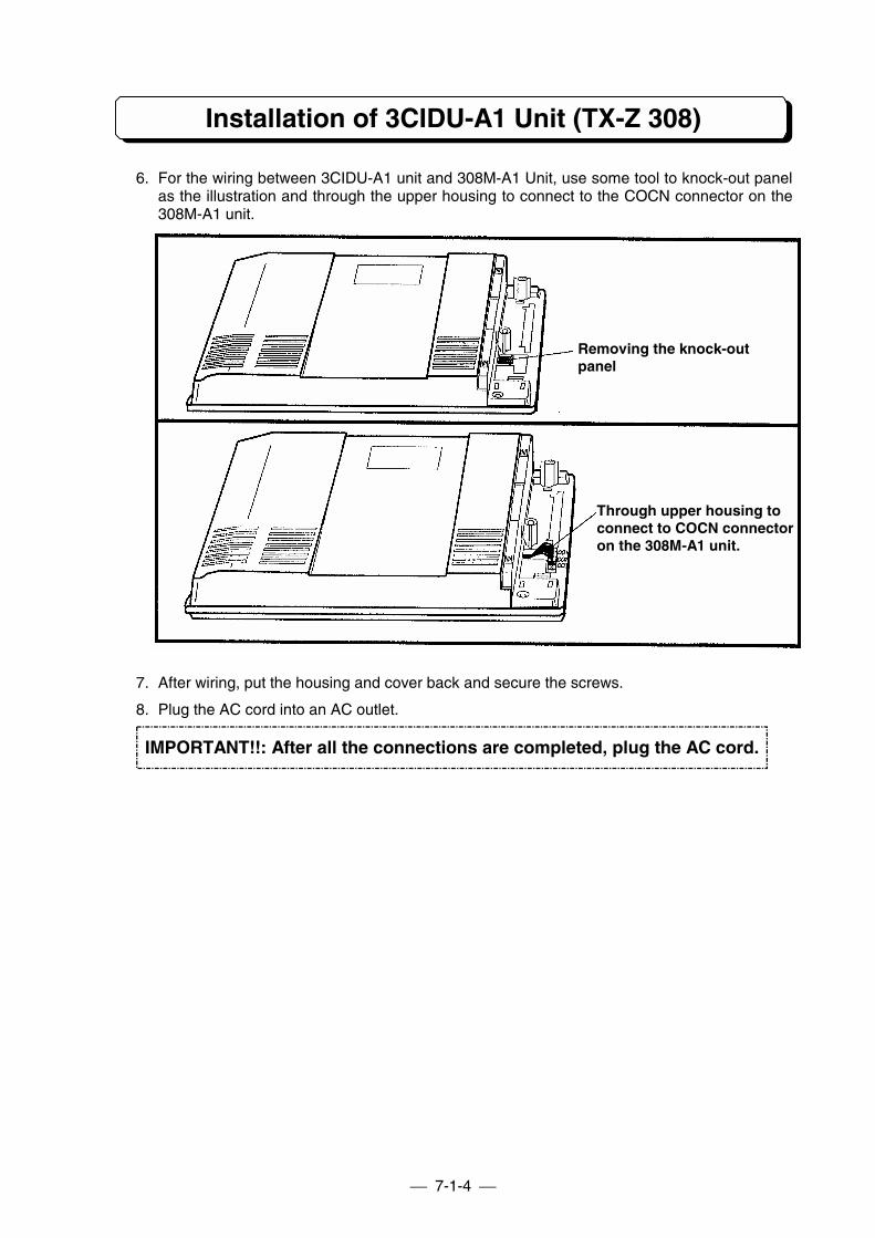
7-1-4
Installation of 3CIDU-A1 Unit (TX-Z 308)
6. For the wiring between 3CIDU-A1 unit and 308M-A1 Unit, use some tool to knock-out panelas the illustration and through the upper housing to connect to the COCN connector on the308M-A1 unit.
7. After wiring, put the housing and cover back and secure the screws.
8. Plug the AC cord into an AC outlet.
Removing the knock-outpanel
Through upper housing toconnect to COCN connectoron the 308M-A1 unit.
IMPORTANT!!: After all the connections are completed, plug the AC cord.
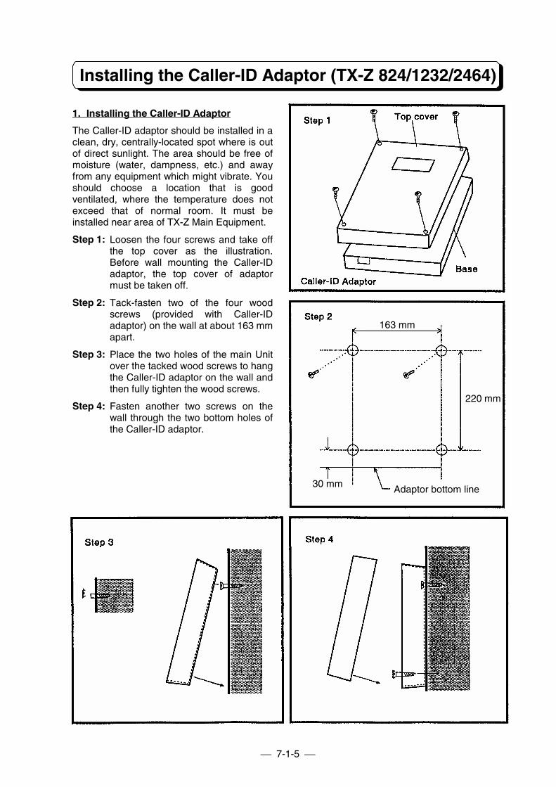
7-1-5
Installing the Caller-ID Adaptor (TX-Z 824/1232/2464)
1. Installing the Caller-ID Adaptor
The Caller-ID adaptor should be installed in aclean, dry, centrally-located spot where is outof direct sunlight. The area should be free ofmoisture (water, dampness, etc.) and awayfrom any equipment which might vibrate. Youshould choose a location that is goodventilated, where the temperature does notexceed that of normal room. It must beinstalled near area of TX-Z Main Equipment.
Step 1: Loosen the four screws and take offthe top cover as the illustration.Before wall mounting the Caller-IDadaptor, the top cover of adaptormust be taken off.
Step 2: Tack-fasten two of the four woodscrews (provided with Caller-IDadaptor) on the wall at about 163 mmapart.
Step 3: Place the two holes of the main Unitover the tacked wood screws to hangthe Caller-ID adaptor on the wall andthen fully tighten the wood screws.
Step 4: Fasten another two screws on thewall through the two bottom holes ofthe Caller-ID adaptor.
163 mm
220 mm
Adaptor bottom line30 mm
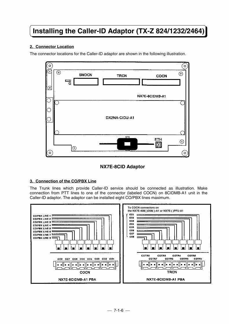
7-1-6
Installing the Caller-ID Adaptor (TX-Z 824/1232/2464)
2. Connector Location
The connector locations for the Caller-ID adaptor are shown in the following illustration.
NX7E-8CID Adaptor
3. Connection of the CO/PBX Line
The Trunk lines which provide Caller-ID service should be connected as illustration. Makeconnection from PTT lines to one of the connector (labeled COCN) on 8CIDMB-A1 unit in theCaller-ID adaptor. The adaptor can be installed eight CO/PBX lines maximum.
To COCN connectors onthe NX7E-408( )/208( )-A1 or NX7E-( )PFU-A1
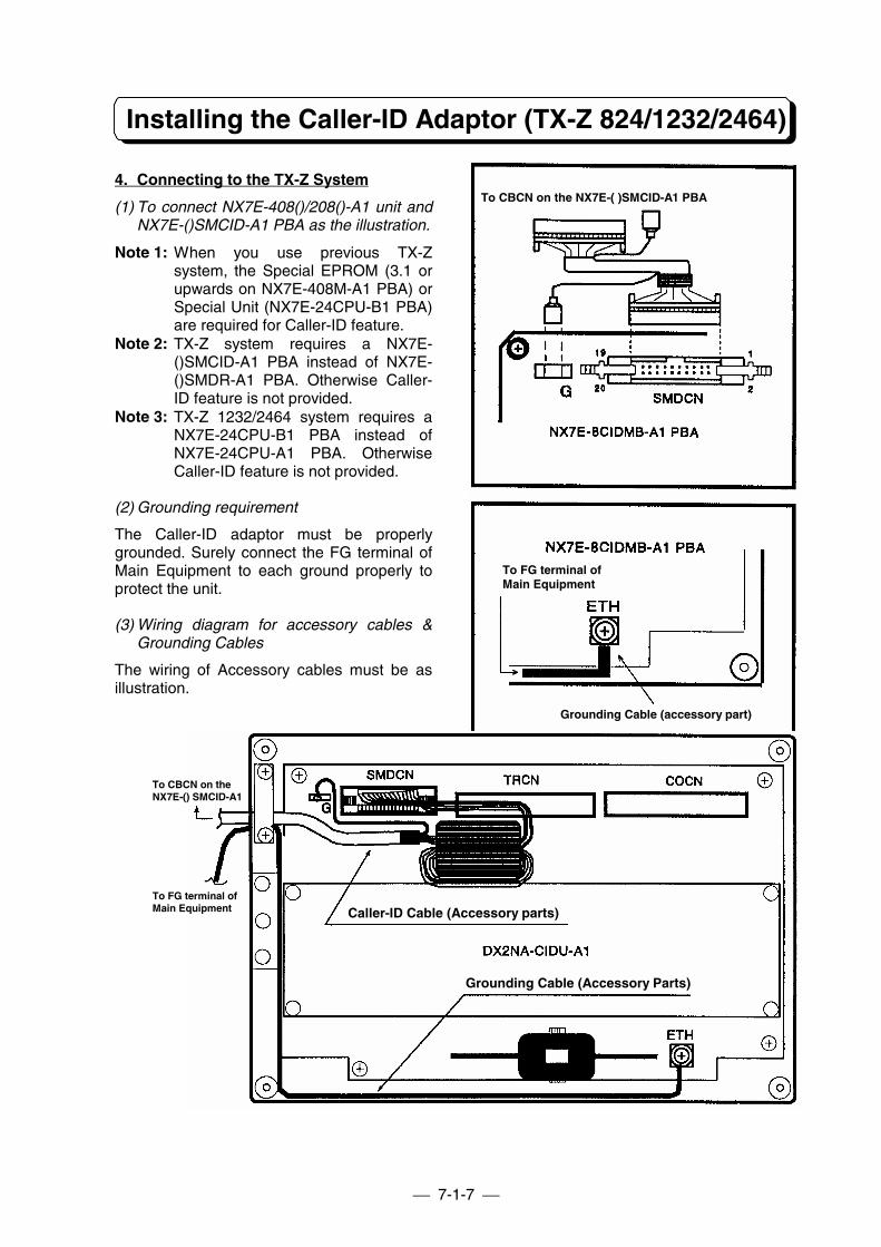
7-1-7
Installing the Caller-ID Adaptor (TX-Z 824/1232/2464)
4. Connecting to the TX-Z System
(1) To connect NX7E-408()/208()-A1 unit andNX7E-()SMCID-A1 PBA as the illustration.
Note 1: When you use previous TX-Zsystem, the Special EPROM (3.1 orupwards on NX7E-408M-A1 PBA) orSpecial Unit (NX7E-24CPU-B1 PBA)are required for Caller-ID feature.
Note 2: TX-Z system requires a NX7E-()SMCID-A1 PBA instead of NX7E-()SMDR-A1 PBA. Otherwise Caller-ID feature is not provided.
Note 3: TX-Z 1232/2464 system requires aNX7E-24CPU-B1 PBA instead ofNX7E-24CPU-A1 PBA. OtherwiseCaller-ID feature is not provided.
(2) Grounding requirement
The Caller-ID adaptor must be properlygrounded. Surely connect the FG terminal ofMain Equipment to each ground properly toprotect the unit.
(3) Wiring diagram for accessory cables &Grounding Cables
The wiring of Accessory cables must be asillustration.
To CBCN on the NX7E-( )SMCID-A1 PBA
To FG terminal ofMain Equipment
Grounding Cable (accessory part)
To CBCN on theNX7E-() SMCID-A1
To FG terminal ofMain Equipment Caller-ID Cable (Accessory parts)
Grounding Cable (Accessory Parts)
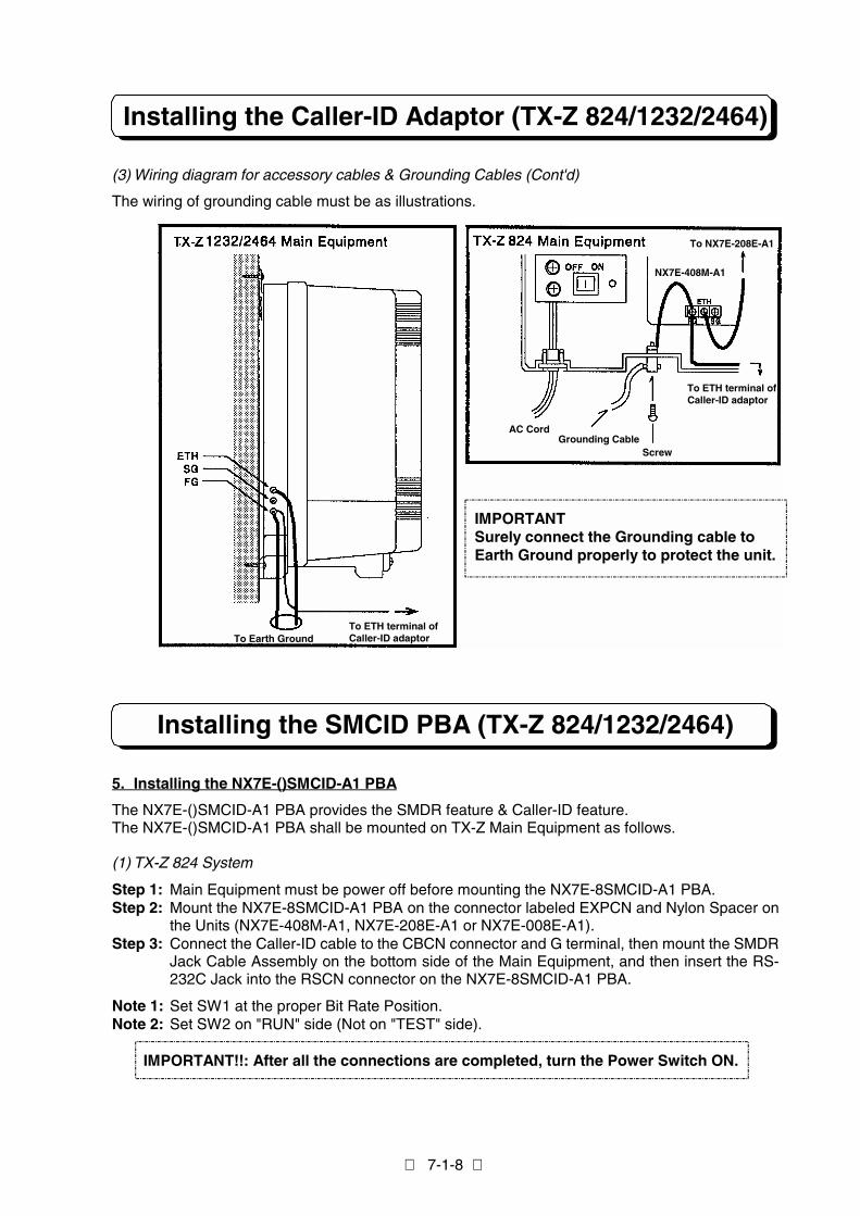
7-1-8
Installing the Caller-ID Adaptor (TX-Z 824/1232/2464)
(3) Wiring diagram for accessory cables & Grounding Cables (Cont'd)
The wiring of grounding cable must be as illustrations.
Installing the SMCID PBA (TX-Z 824/1232/2464)
5. Installing the NX7E-()SMCID-A1 PBA
The NX7E-()SMCID-A1 PBA provides the SMDR feature & Caller-ID feature.The NX7E-()SMCID-A1 PBA shall be mounted on TX-Z Main Equipment as follows.
(1) TX-Z 824 System
Step 1: Main Equipment must be power off before mounting the NX7E-8SMCID-A1 PBA.Step 2: Mount the NX7E-8SMCID-A1 PBA on the connector labeled EXPCN and Nylon Spacer on
the Units (NX7E-408M-A1, NX7E-208E-A1 or NX7E-008E-A1).Step 3: Connect the Caller-ID cable to the CBCN connector and G terminal, then mount the SMDR
Jack Cable Assembly on the bottom side of the Main Equipment, and then insert the RS-232C Jack into the RSCN connector on the NX7E-8SMCID-A1 PBA.
Note 1: Set SW1 at the proper Bit Rate Position.Note 2: Set SW2 on "RUN" side (Not on "TEST" side).
IMPORTANT!!: After all the connections are completed, turn the Power Switch ON.
To NX7E-208E-A1
To ETH terminal ofCaller-ID adaptor
NX7E-408M-A1
AC CordGrounding Cable
Screw
IMPORTANTSurely connect the Grounding cable toEarth Ground properly to protect the unit.
To Earth GroundTo ETH terminal ofCaller-ID adaptor
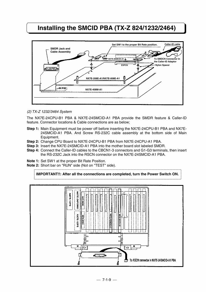
7-1-9
Installing the SMCID PBA (TX-Z 824/1232/2464)
(2) TX-Z 1232/3464 System
The NX7E-24CPU-B1 PBA & NX7E-24SMCID-A1 PBA provide the SMDR feature & Caller-IDfeature. Connector locations & Cable connections are as below;
Step 1: Main Equipment must be power off before inserting the NX7E-24CPU-B1 PBA and NX7E-24SMCID-A1 PBA. And Screw RS-232C cable assembly at the bottom side of MainEquipment.
Step 2: Change CPU Board to NX7E-24CPU-B1 PBA from NX7E-24CPU-A1 PBA.Step 3: Insert the NX7E-24SMCID-A1 PBA into the mother board slot labeled SMDR.Step 4: Connect the Caller-ID cables to the CBCN1-3 connectors and G1-G3 terminals, then insert
the RS-232C Jack into the RSCN connector on the NX7E-24SMCID-A1 PBA.
Note 1: Set SW1 at the proper Bit Rate Position.Note 2: Short bar on "RUN" side (Not on "TEST" side).
IMPORTANT!!: After all the connections are completed, turn the Power Switch ON.
To SMDCN Connector Inthe Caller-ID Adaptor
NX7E-408M-A1
Set SW1 to the proper Bit Rate position. Caller-ID cable
NX7E-8SMCID-A1
NX7E-208E-A1/NX7E-008E-A1
Nylon Spacer
SMDR Jack andCable Assembly
EXPCN
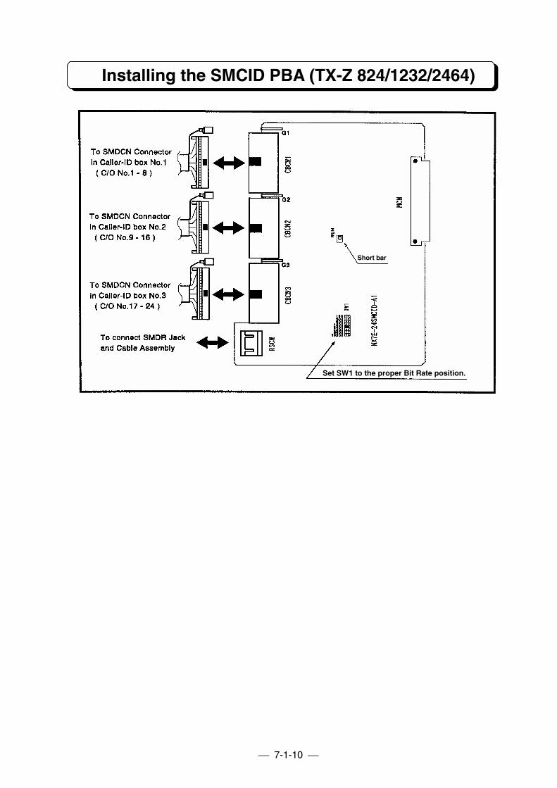
7-1-10
Installing the SMCID PBA (TX-Z 824/1232/2464)
Short barShort bar
Set SW1 to the proper Bit Rate position.
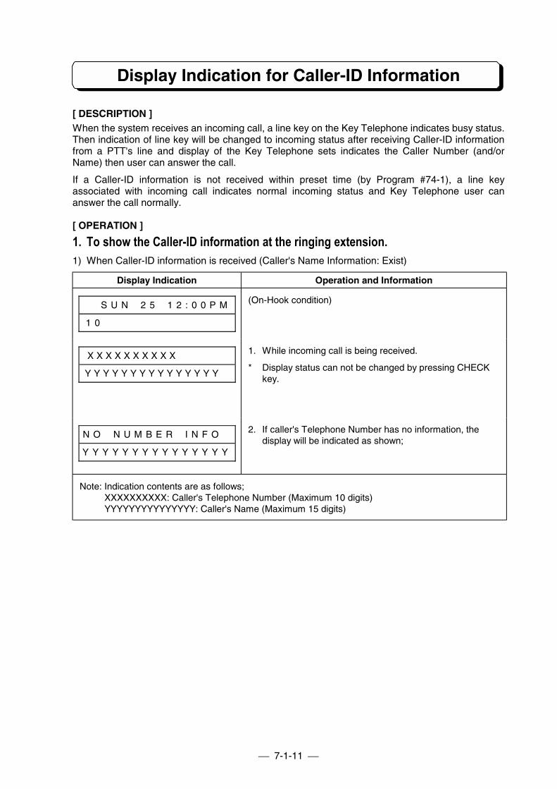
7-1-11
Display Indication for Caller-ID Information
[ DESCRIPTION ]When the system receives an incoming call, a line key on the Key Telephone indicates busy status.Then indication of line key will be changed to incoming status after receiving Caller-ID informationfrom a PTT's line and display of the Key Telephone sets indicates the Caller Number (and/orName) then user can answer the call.
If a Caller-ID information is not received within preset time (by Program #74-1), a line keyassociated with incoming call indicates normal incoming status and Key Telephone user cananswer the call normally.
[ OPERATION ]
1. To show the Caller-ID information at the ringing extension.1) When Caller-ID information is received (Caller's Name Information: Exist)
Display Indication Operation and Information
# # S U N # 2 5 # 1 2 : 0 0 P M
1 0 # # # # # # # # # # # # # #
(On-Hook condition)
X X X X X X X X X X # # # # # #
Y Y Y Y Y Y Y Y Y Y Y Y Y Y Y #
1. While incoming call is being received.
* Display status can not be changed by pressing CHECKkey.
N O # N U M B E R # I N F O #
Y Y Y Y Y Y Y Y Y Y Y Y Y Y Y
2. If caller's Telephone Number has no information, thedisplay will be indicated as shown;
Note: Indication contents are as follows;XXXXXXXXXX: Caller's Telephone Number (Maximum 10 digits)YYYYYYYYYYYYYYY: Caller's Name (Maximum 15 digits)
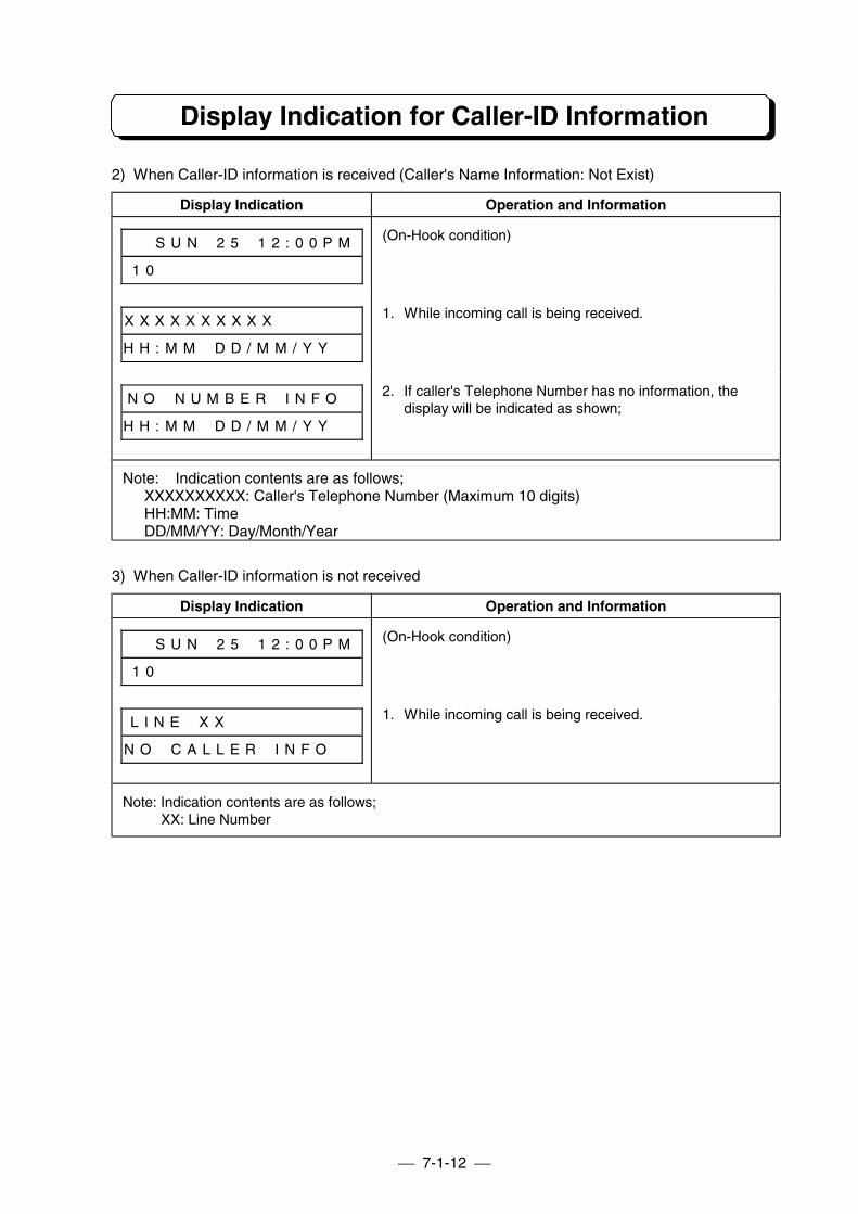
7-1-12
Display Indication for Caller-ID Information
2) When Caller-ID information is received (Caller's Name Information: Not Exist)
Display Indication Operation and Information
# # S U N # 2 5 # 1 2 : 0 0 P M
1 0 # # # # # # # # # # # # # #
(On-Hook condition)
X X X X X X X X X X # # # # # #
H H : M M # D D / M M / Y Y # #
1. While incoming call is being received.
N O # N U M B E R # I N F O #
H H : M M # D D / M M / Y Y # #
2. If caller's Telephone Number has no information, thedisplay will be indicated as shown;
Note: Indication contents are as follows;XXXXXXXXXX: Caller's Telephone Number (Maximum 10 digits)HH:MM: TimeDD/MM/YY: Day/Month/Year
3) When Caller-ID information is not received
Display Indication Operation and Information
# # S U N # 2 5 # 1 2 : 0 0 P M
1 0 # # # # # # # # # # # # # #
(On-Hook condition)
L I N E # X X # # # # # # # # #
N O # C A L L E R # I N F O # #
1. While incoming call is being received.
Note: Indication contents are as follows;XX: Line Number
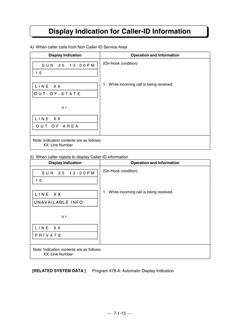
7-1-13
Display Indication for Caller-ID Information
4) When caller calls from Non Caller-ID Service Area
Display Indication Operation and Information
# # S U N # 2 5 # 1 2 : 0 0 P M
1 0 # # # # # # # # # # # # # #
(On-Hook condition)
L I N E # X X # # # # # # # # #
O U T - O F - S T A T E # # # #
o r
L I N E # X X # # # # # # # # #
O U T O F A R E A # # # #
1. While incoming call is being received.
Note: Indication contents are as follows;XX: Line Number
5) When caller rejects to display Caller-ID informationDisplay Indication Operation and Information
# # S U N # 2 5 # 1 2 : 0 0 P M
1 0 # # # # # # # # # # # # # #
(On-Hook condition)
L I N E # X X # # # # # # # # #
UNAVAI LABL E I NFO####
o r
L I N E # X X # # # # # # # # #
P R I V A T E
1. While incoming call is being received.
Note: Indication contents are as follows;XX: Line Number
[RELATED SYSTEM DATA ] Program #78-A: Automatic Display Indication
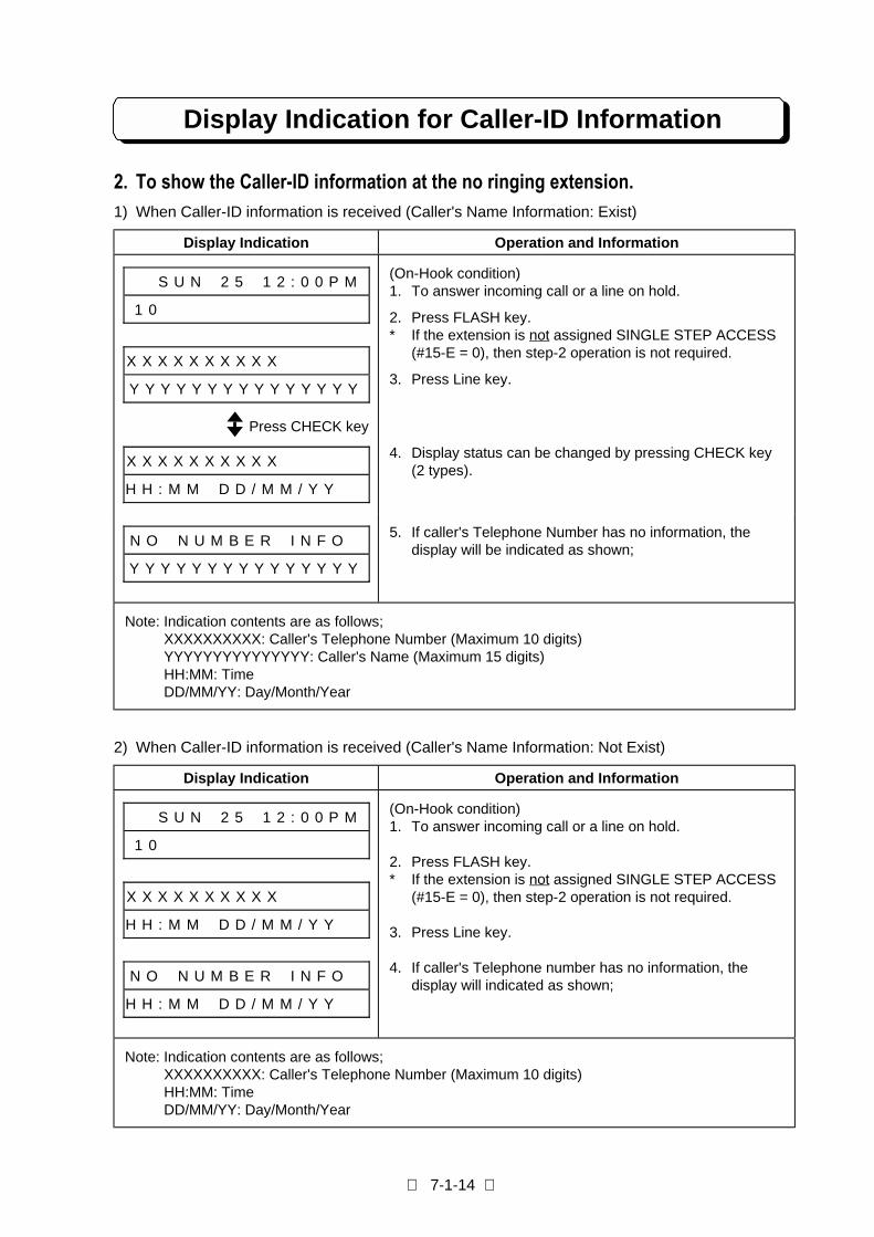
7-1-14
Display Indication for Caller-ID Information
2. To show the Caller-ID information at the no ringing extension.1) When Caller-ID information is received (Caller's Name Information: Exist)
Display Indication Operation and Information
# # S U N # 2 5 # 1 2 : 0 0 P M
1 0 # # # # # # # # # # # # # #
X X X X X X X X X X # # # # # #
Y Y Y Y Y Y Y Y Y Y Y Y Y Y Y
(On-Hook condition)1. To answer incoming call or a line on hold.
2. Press FLASH key.* If the extension is not assigned SINGLE STEP ACCESS
(#15-E = 0), then step-2 operation is not required.
3. Press Line key.
X X X X X X X X X X # # # # # #
H H : M M # D D / M M / Y Y # #
4. Display status can be changed by pressing CHECK key(2 types).
N O # N U M B E R # I N F O #
Y Y Y Y Y Y Y Y Y Y Y Y Y Y Y
5. If caller's Telephone Number has no information, thedisplay will be indicated as shown;
Note: Indication contents are as follows;XXXXXXXXXX: Caller's Telephone Number (Maximum 10 digits)YYYYYYYYYYYYYYY: Caller's Name (Maximum 15 digits)HH:MM: TimeDD/MM/YY: Day/Month/Year
2) When Caller-ID information is received (Caller's Name Information: Not Exist)
Display Indication Operation and Information
# # S U N # 2 5 # 1 2 : 0 0 P M
1 0 # # # # # # # # # # # # # #
X X X X X X X X X X # # # # # #
H H : M M # D D / M M / Y Y # #
N O # N U M B E R # I N F O #
H H : M M # D D / M M / Y Y # #
(On-Hook condition)1. To answer incoming call or a line on hold.
2. Press FLASH key.* If the extension is not assigned SINGLE STEP ACCESS
(#15-E = 0), then step-2 operation is not required.
3. Press Line key.
4. If caller's Telephone number has no information, thedisplay will indicated as shown;
Note: Indication contents are as follows;XXXXXXXXXX: Caller's Telephone Number (Maximum 10 digits)HH:MM: TimeDD/MM/YY: Day/Month/Year
Press CHECK key
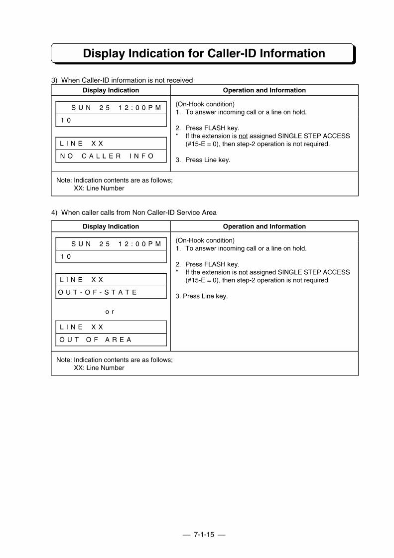
7-1-15
Display Indication for Caller-ID Information
3) When Caller-ID information is not receivedDisplay Indication Operation and Information
# # S U N # 2 5 # 1 2 : 0 0 P M
1 0 # # # # # # # # # # # # # #
L I N E # X X # # # # # # # # #
N O # C A L L E R # I N F O #
(On-Hook condition)1. To answer incoming call or a line on hold.
2. Press FLASH key.* If the extension is not assigned SINGLE STEP ACCESS
(#15-E = 0), then step-2 operation is not required.
3. Press Line key.
Note: Indication contents are as follows;XX: Line Number
4) When caller calls from Non Caller-ID Service Area
Display Indication Operation and Information
# # S U N # 2 5 # 1 2 : 0 0 P M
1 0 # # # # # # # # # # # # # #
L I N E # X X # # # # # # # # #
O U T - O F - S T A T E # # # #
o r
L I N E # X X # # # # # # # # #
O U T O F A R E A # #
(On-Hook condition)1. To answer incoming call or a line on hold.
2. Press FLASH key.* If the extension is not assigned SINGLE STEP ACCESS
(#15-E = 0), then step-2 operation is not required.
3. Press Line key.
Note: Indication contents are as follows;XX: Line Number
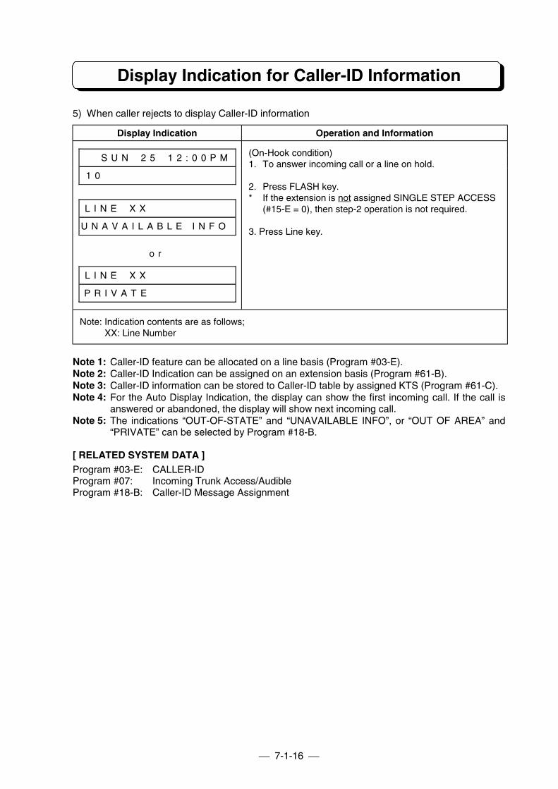
7-1-16
Display Indication for Caller-ID Information
5) When caller rejects to display Caller-ID information
Display Indication Operation and Information
# # S U N # 2 5 # 1 2 : 0 0 P M
1 0 # # # # # # # # # # # # # #
L I N E # X X # # # # # # # # #
U N A V A I L A B L E I N F O #
o r
L I N E # X X # # # # # # # # #
P R I V A T E # # # #
(On-Hook condition)1. To answer incoming call or a line on hold.
2. Press FLASH key.* If the extension is not assigned SINGLE STEP ACCESS
(#15-E = 0), then step-2 operation is not required.
3. Press Line key.
Note: Indication contents are as follows;XX: Line Number
Note 1: Caller-ID feature can be allocated on a line basis (Program #03-E).Note 2: Caller-ID Indication can be assigned on an extension basis (Program #61-B).Note 3: Caller-ID information can be stored to Caller-ID table by assigned KTS (Program #61-C).Note 4: For the Auto Display Indication, the display can show the first incoming call. If the call is
answered or abandoned, the display will show next incoming call.Note 5: The indications “OUT-OF-STATE” and “UNAVAILABLE INFO”, or “OUT OF AREA” and
“PRIVATE” can be selected by Program #18-B.
[ RELATED SYSTEM DATA ]Program #03-E: CALLER-IDProgram #07: Incoming Trunk Access/AudibleProgram #18-B: Caller-ID Message Assignment
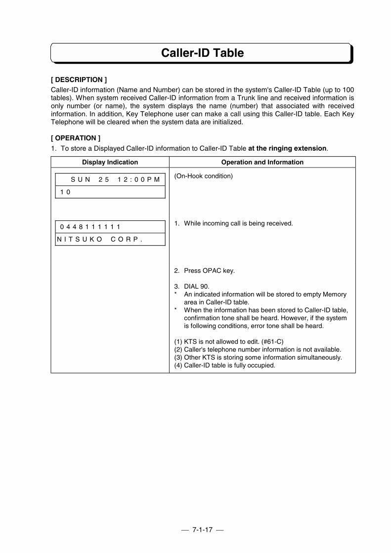
7-1-17
Caller-ID Table
[ DESCRIPTION ]Caller-ID information (Name and Number) can be stored in the system's Caller-ID Table (up to 100tables). When system received Caller-ID information from a Trunk line and received information isonly number (or name), the system displays the name (number) that associated with receivedinformation. In addition, Key Telephone user can make a call using this Caller-ID table. Each KeyTelephone will be cleared when the system data are initialized.
[ OPERATION ]1. To store a Displayed Caller-ID information to Caller-ID Table at the ringing extension.
Display Indication Operation and Information
# # S U N # 2 5 # 1 2 : 0 0 P M
1 0 # # # # # # # # # # # # # #
(On-Hook condition)
0 4 4 8 1 1 1 1 1 1 # # # # # #
N I T S U K O # C O R P . # # #
1. While incoming call is being received.
2. Press OPAC key.
3. DIAL 90.* An indicated information will be stored to empty Memory
area in Caller-ID table.* When the information has been stored to Caller-ID table,
confirmation tone shall be heard. However, if the systemis following conditions, error tone shall be heard.
(1) KTS is not allowed to edit. (#61-C)(2) Caller's telephone number information is not available.(3) Other KTS is storing some information simultaneously.(4) Caller-ID table is fully occupied.
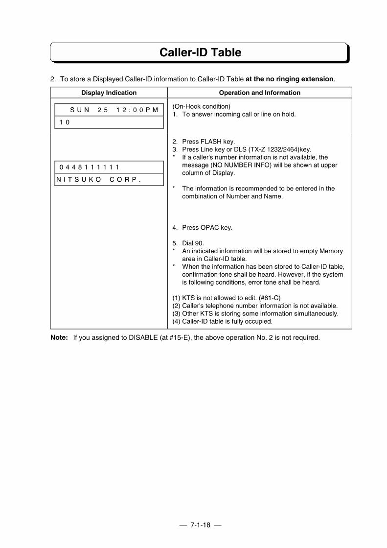
7-1-18
Caller-ID Table
2. To store a Displayed Caller-ID information to Caller-ID Table at the no ringing extension.
Display Indication Operation and Information
# # S U N # 2 5 # 1 2 : 0 0 P M
1 0 # # # # # # # # # # # # # #
(On-Hook condition)1. To answer incoming call or line on hold.
0 4 4 8 1 1 1 1 1 1 # # # # # #
N I T S U K O # C O R P . # # #
2. Press FLASH key.3. Press Line key or DLS (TX-Z 1232/2464)key.* If a caller's number information is not available, the
message (NO NUMBER INFO) will be shown at uppercolumn of Display.
* The information is recommended to be entered in thecombination of Number and Name.
4. Press OPAC key.
5. Dial 90.* An indicated information will be stored to empty Memory
area in Caller-ID table.* When the information has been stored to Caller-ID table,
confirmation tone shall be heard. However, if the systemis following conditions, error tone shall be heard.
(1) KTS is not allowed to edit. (#61-C)(2) Caller's telephone number information is not available.(3) Other KTS is storing some information simultaneously.(4) Caller-ID table is fully occupied.
Note: If you assigned to DISABLE (at #15-E), the above operation No. 2 is not required.
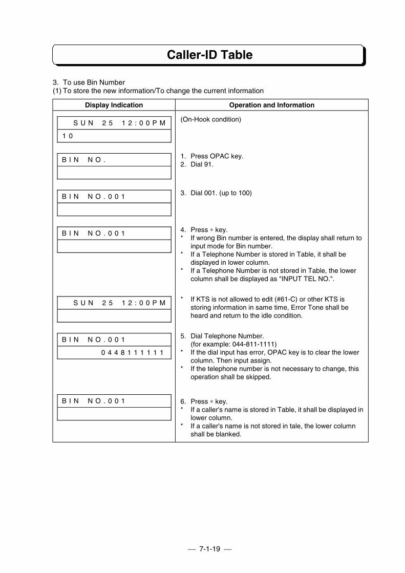
7-1-19
Caller-ID Table
3. To use Bin Number(1) To store the new information/To change the current information
Display Indication Operation and Information
# # S U N # 2 5 # 1 2 : 0 0 P M
1 0 # # # # # # # # # # # # # #
(On-Hook condition)
B I N # N O . # # # # # # # # # 1. Press OPAC key.2. Dial 91.
B I N # N O . 0 0 1 # # # # # # 3. Dial 001. (up to 100)
B I N # N O . 0 0 1 # # # # # # 4. Press ∗ key.* If wrong Bin number is entered, the display shall return to
input mode for Bin number.* If a Telephone Number is stored in Table, it shall be
displayed in lower column.* If a Telephone Number is not stored in Table, the lower
column shall be displayed as "INPUT TEL NO.".
# # S U N # 2 5 # 1 2 : 0 0 P M * If KTS is not allowed to edit (#61-C) or other KTS isstoring information in same time, Error Tone shall beheard and return to the idle condition.
B I N # N O . 0 0 1 # # # # # #
# # # # # # 0 4 4 8 1 1 1 1 1 1
5. Dial Telephone Number.(for example: 044-811-1111)
* If the dial input has error, OPAC key is to clear the lowercolumn. Then input assign.
* If the telephone number is not necessary to change, thisoperation shall be skipped.
B I N # N O . 0 0 1 # # # # # # 6. Press ∗ key.* If a caller's name is stored in Table, it shall be displayed in
lower column.* If a caller's name is not stored in tale, the lower column
shall be blanked.
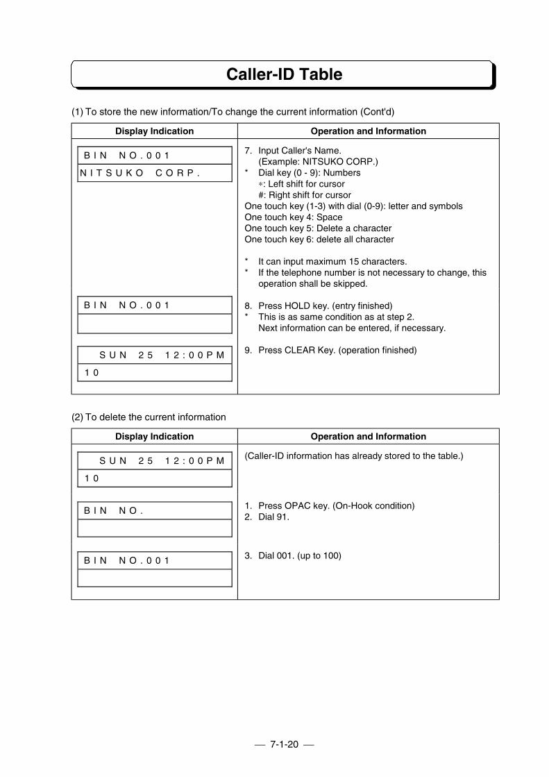
7-1-20
Caller-ID Table
(1) To store the new information/To change the current information (Cont'd)
Display Indication Operation and Information
B I N # N O . 0 0 1 # # # # # #
N I T S U K O # C O R P . # # #
7. Input Caller's Name.(Example: NITSUKO CORP.)
* Dial key (0 - 9): Numbers∗: Left shift for cursor#: Right shift for cursor
One touch key (1-3) with dial (0-9): letter and symbolsOne touch key 4: SpaceOne touch key 5: Delete a characterOne touch key 6: delete all character
* It can input maximum 15 characters.* If the telephone number is not necessary to change, this
operation shall be skipped.
B I N # N O . 0 0 1 # # # # # #
# # S U N # 2 5 # 1 2 : 0 0 P M
1 0 # # # # # # # # # # # # # #
8. Press HOLD key. (entry finished)* This is as same condition as at step 2.
Next information can be entered, if necessary.
9. Press CLEAR Key. (operation finished)
(2) To delete the current information
Display Indication Operation and Information
# # S U N # 2 5 # 1 2 : 0 0 P M
1 0 # # # # # # # # # # # # # #
(Caller-ID information has already stored to the table.)
B I N # N O . # # # # # # # # # 1. Press OPAC key. (On-Hook condition)2. Dial 91.
B I N # N O . 0 0 1 # # # # # # 3. Dial 001. (up to 100)
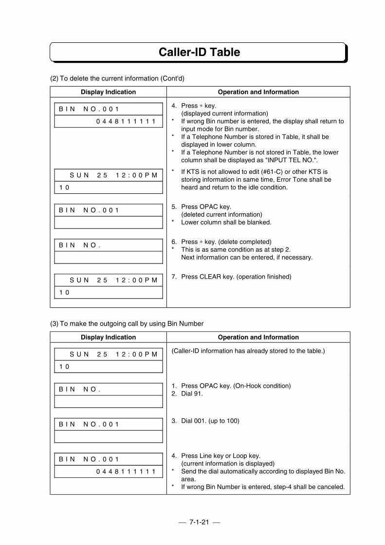
7-1-21
Caller-ID Table
(2) To delete the current information (Cont'd)
Display Indication Operation and Information
B I N # N O . 0 0 1 # # # # # #
# # # # # # 0 4 4 8 1 1 1 1 1 1
4. Press ∗ key.(displayed current information)
* If wrong Bin number is entered, the display shall return toinput mode for Bin number.
* If a Telephone Number is stored in Table, it shall bedisplayed in lower column.
* If a Telephone Number is not stored in Table, the lowercolumn shall be displayed as "INPUT TEL NO.".
# # S U N # 2 5 # 1 2 : 0 0 P M
1 0 # # # # # # # # # # # # # #
* If KTS is not allowed to edit (#61-C) or other KTS isstoring information in same time, Error Tone shall beheard and return to the idle condition.
B I N # N O . 0 0 1 # # # # # # 5. Press OPAC key.(deleted current information)
* Lower column shall be blanked.
B I N # N O . # # # # # # # # # 6. Press ∗ key. (delete completed)* This is as same condition as at step 2.
Next information can be entered, if necessary.
# # S U N # 2 5 # 1 2 : 0 0 P M
1 0 # # # # # # # # # # # # # #
7. Press CLEAR key. (operation finished)
(3) To make the outgoing call by using Bin Number
Display Indication Operation and Information
# # S U N # 2 5 # 1 2 : 0 0 P M
1 0 # # # # # # # # # # # # # #
(Caller-ID information has already stored to the table.)
B I N # N O . # # # # # # # # # 1. Press OPAC key. (On-Hook condition)2. Dial 91.
B I N # N O . 0 0 1 # # # # # # 3. Dial 001. (up to 100)
B I N # N O . 0 0 1 # # # # # #
# # # # # # 0 4 4 8 1 1 1 1 1 1
4. Press Line key or Loop key.(current information is displayed)
* Send the dial automatically according to displayed Bin No.area.
* If wrong Bin Number is entered, step-4 shall be canceled.
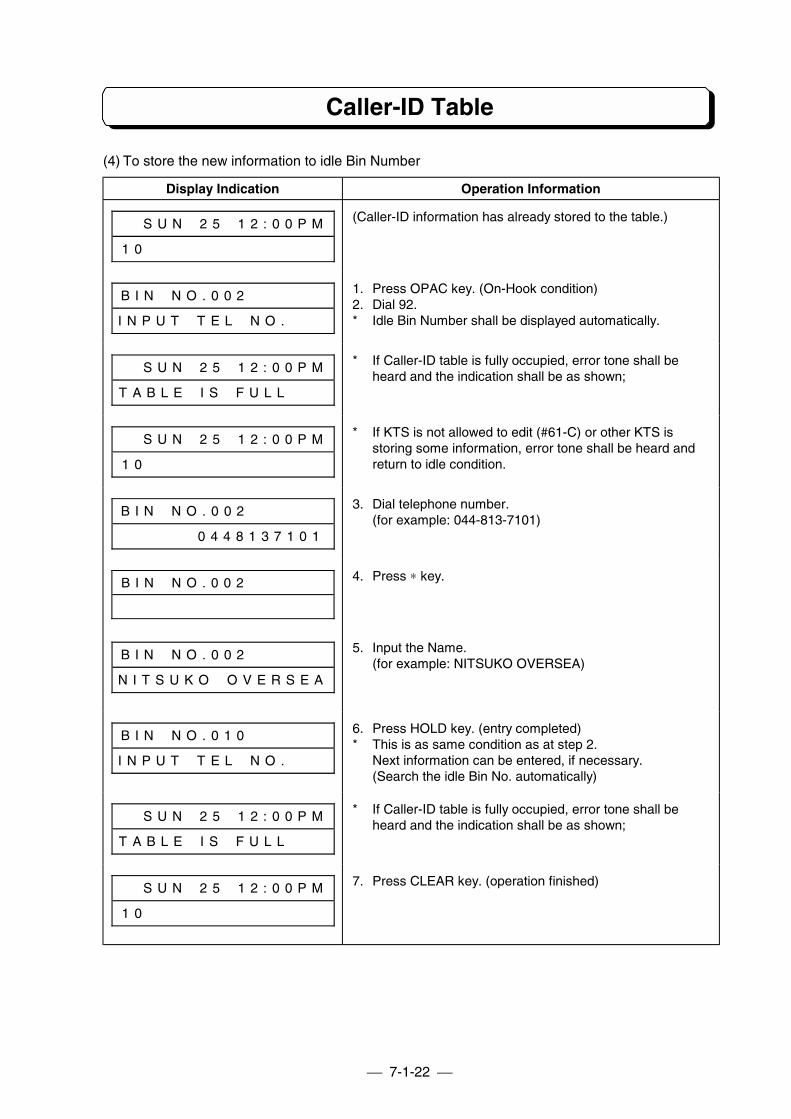
7-1-22
Caller-ID Table
(4) To store the new information to idle Bin Number
Display Indication Operation Information
# # S U N # 2 5 # 1 2 : 0 0 P M
1 0 # # # # # # # # # # # # # #
(Caller-ID information has already stored to the table.)
B I N # N O . 0 0 2 # # # # # #
I N P U T # T E L # N O . # # #
1. Press OPAC key. (On-Hook condition)2. Dial 92.* Idle Bin Number shall be displayed automatically.
# # S U N # 2 5 # 1 2 : 0 0 P M
T A B L E # I S # F U L L # # #
* If Caller-ID table is fully occupied, error tone shall beheard and the indication shall be as shown;
# # S U N # 2 5 # 1 2 : 0 0 P M
1 0 # # # # # # # # # # # # # #
* If KTS is not allowed to edit (#61-C) or other KTS isstoring some information, error tone shall be heard andreturn to idle condition.
B I N # N O . 0 0 2 # # # # # #
# # # # # # 0 4 4 8 1 3 7 1 0 1
3. Dial telephone number.(for example: 044-813-7101)
B I N # N O . 0 0 2 # # # # # # 4. Press ∗ key.
B I N # N O . 0 0 2 # # # # # #
N I T S U K O # O V E R S E A
5. Input the Name.(for example: NITSUKO OVERSEA)
B I N # N O . 0 1 0 # # # # # #
I N P U T # T E L # N O . # # #
6. Press HOLD key. (entry completed)* This is as same condition as at step 2.
Next information can be entered, if necessary.(Search the idle Bin No. automatically)
# # S U N # 2 5 # 1 2 : 0 0 P M
T A B L E # I S # F U L L # # #
* If Caller-ID table is fully occupied, error tone shall beheard and the indication shall be as shown;
# # S U N # 2 5 # 1 2 : 0 0 P M
1 0 # # # # # # # # # # # # # #
7. Press CLEAR key. (operation finished)
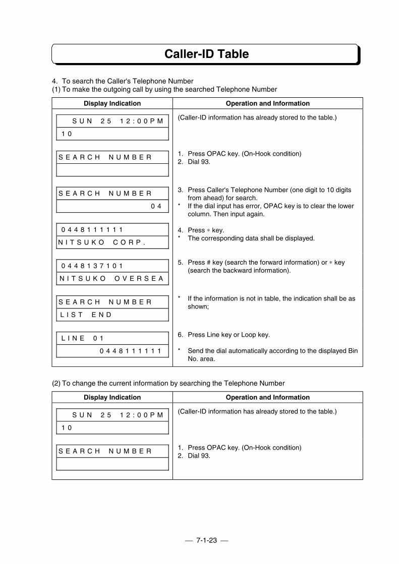
7-1-23
Caller-ID Table
4. To search the Caller's Telephone Number(1) To make the outgoing call by using the searched Telephone Number
Display Indication Operation and Information
# # S U N # 2 5 # 1 2 : 0 0 P M
1 0 # # # # # # # # # # # # # #
(Caller-ID information has already stored to the table.)
S E A R C H # N U M B E R # # 1. Press OPAC key. (On-Hook condition)2. Dial 93.
S E A R C H # N U M B E R # #
# # # # # # # # # # # # # # 0 4
3. Press Caller's Telephone Number (one digit to 10 digitsfrom ahead) for search.
* If the dial input has error, OPAC key is to clear the lowercolumn. Then input again.
0 4 4 8 1 1 1 1 1 1 # # # # # #
N I T S U K O # C O R P . # # #
4. Press ∗ key.* The corresponding data shall be displayed.
0 4 4 8 1 3 7 1 0 1 # # # # # #
N I T S U K O # O V E R S E A
5. Press # key (search the forward information) or ∗ key(search the backward information).
S E A R C H # N U M B E R # #
L I S T # E N D # # # # # # # #
* If the information is not in table, the indication shall be asshown;
L I N E # 0 1 # # # # # # # # #
# # # # # # 0 4 4 8 1 1 1 1 1 1
6. Press Line key or Loop key.
* Send the dial automatically according to the displayed BinNo. area.
(2) To change the current information by searching the Telephone Number
Display Indication Operation and Information
# # S U N # 2 5 # 1 2 : 0 0 P M
1 0 # # # # # # # # # # # # # #
(Caller-ID information has already stored to the table.)
S E A R C H # N U M B E R # # 1. Press OPAC key. (On-Hook condition)2. Dial 93.
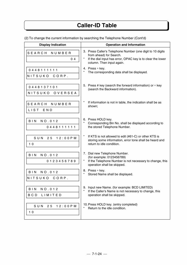
7-1-24
Caller-ID Table
(2) To change the current information by searching the Telephone Number (Cont'd)
Display Indication Operation and Information
S E A R C H # N U M B E R # #
# # # # # # # # # # # # # # 0 4
3. Press Caller's Telephone Number (one digit to 10 digitsfrom ahead) for Search.
* If the dial input has error, OPAC key is to clear the lowercolumn. Then input again.
0 4 4 8 1 1 1 1 1 1 # # # # # #
N I T S U K O # C O R P . # # #
4. Press ∗ key.* The corresponding data shall be displayed.
0 4 4 8 1 3 7 1 0 1 # # # # # #
N I T S U K O # O V E R S E A
5. Press # key (search the forward information) or ∗ key(search the Backward information).
S E A R C H # N U M B E R # #
L I S T # E N D # # # # # # # #
* If information is not in table, the indication shall be asshown;
B I N # N O . 0 1 2 # # # # # #
# # # # # # 0 4 4 8 1 1 1 1 1 1
6. Press HOLD key.* Corresponding Bin No. shall be displayed according to
the stored Telephone Number.
# # S U N # 2 5 # 1 2 : 0 0 P M
1 0 # # # # # # # # # # # # # #
* If KTS is not allowed to edit (#61-C) or other KTS isstoring some information, error tone shall be heard andreturn to idle condition.
B I N # N O . 0 1 2 # # # # # #
# # # # # # 0 1 2 3 4 5 6 7 8 9
7. Dial new Telephone Number.(for example: 0123456789)
* If the Telephone Number is not necessary to change, thisoperation shall be skipped.
B I N # N O . 0 1 2 # # # # # #
N I T S U K O # C O R P . # # #
8. Press ∗ key.* Stored Name shall be displayed.
B I N # N O . 0 1 2 # # # # # #
B C D # L I M I T E D # # # # #
9. Input new Name. (for example: BCD LIMITED)* If the Caller's Name is not necessary to change, this
operation shall be skipped.
# # S U N # 2 5 # 1 2 : 0 0 P M
1 0 # # # # # # # # # # # # # #
10.Press HOLD key. (entry completed)* Return to the idle condition.
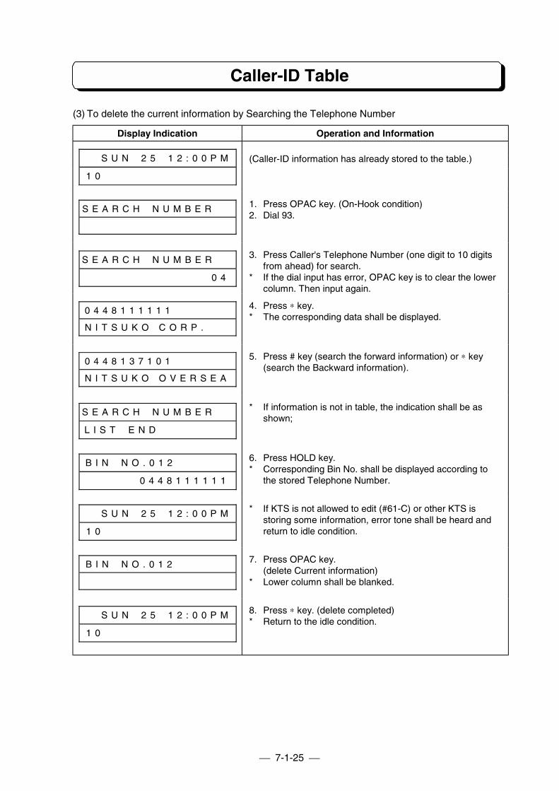
7-1-25
Caller-ID Table
(3) To delete the current information by Searching the Telephone Number
Display Indication Operation and Information
# # S U N # 2 5 # 1 2 : 0 0 P M
1 0 # # # # # # # # # # # # # #
(Caller-ID information has already stored to the table.)
S E A R C H # N U M B E R # # 1. Press OPAC key. (On-Hook condition)2. Dial 93.
S E A R C H # N U M B E R # #
# # # # # # # # # # # # # # 0 4
3. Press Caller's Telephone Number (one digit to 10 digitsfrom ahead) for search.
* If the dial input has error, OPAC key is to clear the lowercolumn. Then input again.
0 4 4 8 1 1 1 1 1 1 # #
N I T S U K O C O R P .
4. Press ∗ key.* The corresponding data shall be displayed.
0 4 4 8 1 3 7 1 0 1 # #
N I T S U K O O V E R S E A
5. Press # key (search the forward information) or ∗ key(search the Backward information).
S E A R C H # N U M B E R # #
L I S T # E N D # # # # # # # #
* If information is not in table, the indication shall be asshown;
B I N # N O . 0 1 2 # # # # # #
# # # # # # 0 4 4 8 1 1 1 1 1 1
6. Press HOLD key.* Corresponding Bin No. shall be displayed according to
the stored Telephone Number.
# # S U N # 2 5 # 1 2 : 0 0 P M
1 0 # # # # # # # # # # # # # #
* If KTS is not allowed to edit (#61-C) or other KTS isstoring some information, error tone shall be heard andreturn to idle condition.
B I N # N O . 0 1 2 # # # # # # 7. Press OPAC key.(delete Current information)
* Lower column shall be blanked.
# # S U N # 2 5 # 1 2 : 0 0 P M
1 0 # # # # # # # # # # # # # #
8. Press ∗ key. (delete completed)* Return to the idle condition.
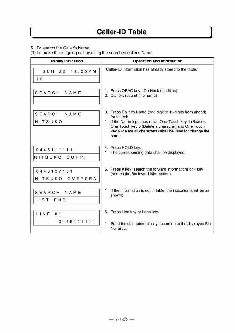
7-1-26
Caller-ID Table
5. To search the Caller's Name(1) To make the outgoing call by using the searched caller's Name
Display Indication Operation and Information
# # S U N # 2 5 # 1 2 : 0 0 P M
1 0 # # # # # # # # # # # # # #
(Caller-ID information has already stored to the table.)
S E A R C H # N A M E # # # # 1. Press OPAC key. (On Hook condition)2. Dial 94. (search the name)
S E A R C H # N A M E # # # #
N I T S U K O # # # # # # # # #
3. Press Caller's Name (one digit to 15 digits from ahead)for search.
* If the Name input has error, One-Touch key 4 (Space),One Touch key 5 (Delete a character) and One Touchkey 6 (delete all characters) shall be used for change thename.
0 4 4 8 1 1 1 1 1 1 # # # # # #
N I T S U K O # C O R P . # # #
4. Press HOLD key.* The corresponding data shall be displayed.
0 4 4 8 1 3 7 1 0 1 # # # # # #
N I T S U K O # O V E R S E A
5. Press # key (search the forward information) or ∗ key(search the Backward information).
S E A R C H # N A M E # # # #
L I S T # E N D # # # # # # # #
* If the information is not in table, the indication shall be asshown;
L I N E # 0 1 # # # # # # # # #
# # # # # # 0 4 4 8 1 1 1 1 1 1
6. Press Line key or Loop key.
* Send the dial automatically according to the displayed BinNo. area.
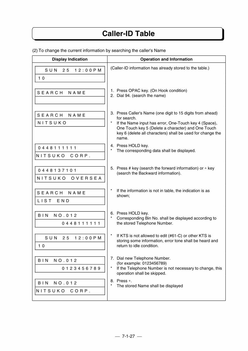
7-1-27
Caller-ID Table
(2) To change the current information by searching the caller's Name
Display Indication Operation and Information
# # S U N # 2 5 # 1 2 : 0 0 P M
1 0 # # # # # # # # # # # # # #
(Caller-ID information has already stored to the table.)
S E A R C H # N A M E # # # # 1. Press OPAC key. (On Hook condition)2. Dial 94. (search the name)
S E A R C H # N A M E # # # #
N I T S U K O
3. Press Caller's Name (one digit to 15 digits from ahead)for search.
* If the Name input has error, One-Touch key 4 (Space),One Touch key 5 (Delete a character) and One Touchkey 6 (delete all characters) shall be used for change thename.
0 4 4 8 1 1 1 1 1 1 # # # # # #
N I T S U K O # C O R P . # # #
4. Press HOLD key.* The corresponding data shall be displayed.
0 4 4 8 1 3 7 1 0 1 # # # # # #
N I T S U K O # O V E R S E A
5. Press # key (search the forward information) or ∗ key(search the Backward information).
S E A R C H # N A M E # # # #
L I S T # E N D # # # # # # # #
* If the information is not in table, the indication is asshown;
B I N # N O . 0 1 2 # # # # # #
# # # # # # 0 4 4 8 1 1 1 1 1 1
6. Press HOLD key.* Corresponding Bin No. shall be displayed according to
the stored Telephone Number.
# # S U N # 2 5 # 1 2 : 0 0 P M
1 0 # # # # # # # # # # # # # #
* If KTS is not allowed to edit (#61-C) or other KTS isstoring some information, error tone shall be heard andreturn to idle condition.
B I N # N O . 0 1 2 # # # # # #
# # # # # # 0 1 2 3 4 5 6 7 8 9
7. Dial new Telephone Number.(for example: 0123456789)
* If the Telephone Number is not necessary to change, thisoperation shall be skipped.
B I N # N O . 0 1 2 # # # # # #
N I T S U K O # C O R P . # # #
8. Press ∗.* The stored Name shall be displayed
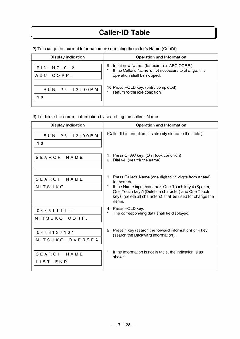
7-1-28
Caller-ID Table
(2) To change the current information by searching the caller's Name (Cont'd)
Display Indication Operation and Information
B I N # N O . 0 1 2 # # # # # #
A B C # C O R P . # # # # # # #
9. Input new Name. (for example: ABC CORP.)* If the Caller's Name is not necessary to change, this
operation shall be skipped.
# # S U N # 2 5 # 1 2 : 0 0 P M
1 0 # # # # # # # # # # # # # #
10.Press HOLD key. (entry completed)* Return to the idle condition.
(3) To delete the current information by searching the caller's Name
Display Indication Operation and Information
# # S U N # 2 5 # 1 2 : 0 0 P M
1 0 # # # # # # # # # # # # # #
(Caller-ID information has already stored to the table.)
S E A R C H # N A M E # # # # 1. Press OPAC key. (On Hook condition)2. Dial 94. (search the name)
S E A R C H # N A M E # # # #
N I T S U K O # # # # # # # # #
3. Press Caller's Name (one digit to 15 digits from ahead)for search.
* If the Name input has error, One-Touch key 4 (Space),One Touch key 5 (Delete a character) and One Touchkey 6 (delete all characters) shall be used for change thename.
0 4 4 8 1 1 1 1 1 1 # # # # # #
N I T S U K O # C O R P . # # #
4. Press HOLD key.* The corresponding data shall be displayed.
0 4 4 8 1 3 7 1 0 1 # # # # # #
N I T S U K O # O V E R S E A
5. Press # key (search the forward information) or ∗ key(search the Backward information).
S E A R C H # N A M E # # # #
L I S T # E N D # # # # # # # #
* If the information is not in table, the indication is asshown;
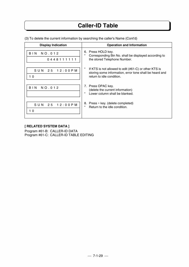
7-1-29
Caller-ID Table
(3) To delete the current information by searching the caller's Name (Cont'd)
Display Indication Operation and Information
B I N # N O . 0 1 2 # # # # # #
# # # # # # 0 4 4 8 1 1 1 1 1 1
6. Press HOLD key.* Corresponding Bin No. shall be displayed according to
the stored Telephone Number.
# # S U N # 2 5 # 1 2 : 0 0 P M
1 0 # # # # # # # # # # # # # #
* If KTS is not allowed to edit (#61-C) or other KTS isstoring some information, error tone shall be heard andreturn to idle condition.
B I N # N O . 0 1 2 # # # # # # 7. Press OPAC key.(delete the current information)
* Lower column shall be blanked.
# # S U N # 2 5 # 1 2 : 0 0 P M
1 0 # # # # # # # # # # # # # #
8. Press ∗ key. (delete completed)* Return to the idle condition.
[ RELATED SYSTEM DATA ]Program #61-B: CALLER-ID DATAProgram #61-C: CALLER-ID TABLE EDITING
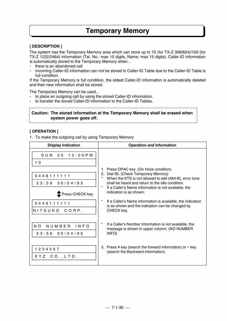
7-1-30
Temporary Memory
[ DESCRIPTION ]The system has the Temporary Memory area which can store up to 70 (for TX-Z 308/824)/100 (forTX-Z 1232/2464) information (Tel. No.: max 10 digits, Name: max 15 digits). Caller-ID informationis automatically stored to the Temporary Memory when...- there is an abandoned call- incoming Caller-ID information can not be stored to Caller-ID Table due to the Caller-ID Table is
full condition.If the Temporary Memory is full condition, the oldest Caller-ID information is automatically deletedand then new information shall be stored.
The Temporary Memory can be used...- to place an outgoing call by using the stored Caller-ID information.- to transfer the stored Caller-ID information to the Caller-ID Tables.
[ OPERATION ]1. To make the outgoing call by using Temporary Memory
Display Indication Operation and Information
# # S U N # 2 5 # 1 2 : 0 0 P M
1 0 # # # # # # # # # # # # # #
0 4 4 8 1 1 1 1 1 1 # # # # # #
2 3 : 5 6 # 3 0 / 0 4 / 9 5 # #
1. Press OPAC key. (On Hook condition)2. Dial 95. (Check Temporary Memory)* When the KTS is not allowed to edit (#64-B), error tone
shall be heard and return to the idle condition.* If a Caller's Name information is not available, the
indication is as shown;
0 4 4 8 1 1 1 1 1 1 # # # # # #
N I T S U K O # C O R P . # # #
* If a Caller's Name information is available, the indicationis as shown and the indication can be changed byCHECK key.
N O # N U M B E R # I N F O #
2 3 : 5 6 # 3 0 / 0 4 / 9 5 # #
* If a Caller's Number Information is not available, themessage is shown in upper column. (NO NUMBERINFO)
1 2 3 4 5 6 7 # # # # # # # # #
X Y Z # C O . , L T D . # # # #
3. Press # key (search the forward information) or ∗ key(search the Backward information).
Caution: The stored information at the Temporary Memory shall be erased whensystem power goes off.
Press CHECK key
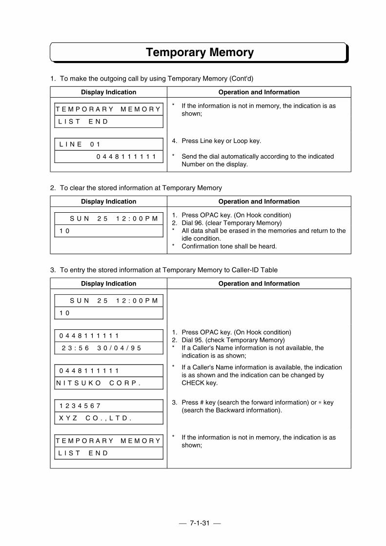
7-1-31
Temporary Memory
1. To make the outgoing call by using Temporary Memory (Cont'd)
Display Indication Operation and Information
T E M P O R A R Y # M E M O R Y
L I S T # E N D # # # # # # # #
* If the information is not in memory, the indication is asshown;
L I N E # 0 1 # # # # # # # # #
# # # # # # 0 4 4 8 1 1 1 1 1 1
4. Press Line key or Loop key.
* Send the dial automatically according to the indicatedNumber on the display.
2. To clear the stored information at Temporary Memory
Display Indication Operation and Information
# # S U N # 2 5 # 1 2 : 0 0 P M
1 0 # # # # # # # # # # # # # #
1. Press OPAC key. (On Hook condition)2. Dial 96. (clear Temporary Memory)* All data shall be erased in the memories and return to the
idle condition.* Confirmation tone shall be heard.
3. To entry the stored information at Temporary Memory to Caller-ID Table
Display Indication Operation and Information
# # S U N # 2 5 # 1 2 : 0 0 P M
1 0 # # # # # # # # # # # # # #
0 4 4 8 1 1 1 1 1 1 # # # # # #
2 3 : 5 6 # 3 0 / 0 4 / 9 5 # #
1. Press OPAC key. (On Hook condition)2. Dial 95. (check Temporary Memory)* If a Caller's Name information is not available, the
indication is as shown;
0 4 4 8 1 1 1 1 1 1 # # # # # #
N I T S U K O # C O R P . # # #
* If a Caller's Name information is available, the indicationis as shown and the indication can be changed byCHECK key.
1 2 3 4 5 6 7 # # # # # # # # #
X Y Z # C O . , L T D . # # # #
3. Press # key (search the forward information) or ∗ key(search the Backward information).
T E M P O R A R Y # M E M O R Y
L I S T # E N D # # # # # # # #
* If the information is not in memory, the indication is asshown;
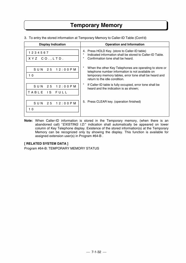
7-1-32
Temporary Memory
3. To entry the stored information at Temporary Memory to Caller-ID Table (Cont'd)
Display Indication Operation and Information
1 2 3 4 5 6 7 # # # # # # # # #
X Y Z # C O . , L T D . # # # #
# # S U N # 2 5 # 1 2 : 0 0 P M
1 0 # # # # # # # # # # # # # #
4. Press HOLD Key. (store to Caller-ID table)* Indicated information shall be stored to Caller-ID Table.* Confirmation tone shall be heard.
* When the other Key Telephones are operating to store ortelephone number information is not available ontemporary memory tables, error tone shall be heard andreturn to the idle condition.
# # S U N # 2 5 # 1 2 : 0 0 P M
T A B L E # I S # F U L L # # #
* If Caller-ID table is fully occupied, error tone shall beheard and the indication is as shown;
# # S U N # 2 5 # 1 2 : 0 0 P M
1 0 # # # # # # # # # # # # # #
5. Press CLEAR key. (operation finished)
Note: When Caller-ID information is stored in the Temporary memory, (when there is anabandoned call) "EXISTING I.D." indication shall automatically be appeared on lowercolumn of Key Telephone display. Existence of the stored information(s) at the TemporaryMemory can be recognized only by showing the display. This function is available forassigned extension user(s) in Program #64-B .
[ RELATED SYSTEM DATA ]Program #64-B: TEMPORARY MEMORY STATUS
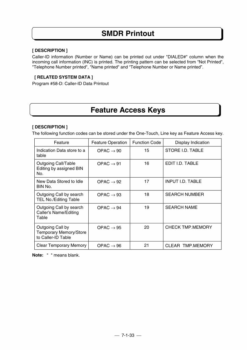
7-1-33
SMDR Printout
[ DESCRIPTION ]Caller-ID information (Number or Name) can be printed out under "DIALED#" column when theincoming call information (INC) is printed. The printing pattern can be selected from "Not Printed","Telephone Number printed", "Name printed" and “Telephone Number or Name printed”.
[ RELATED SYSTEM DATA ]Program #58-D: Caller-ID Data Printout
Feature Access Keys
[ DESCRIPTION ]The following function codes can be stored under the One-Touch, Line key as Feature Access key.
Feature Feature Operation Function Code Display Indication
Indication Data store to atable
OPAC → 90 15 STORE I.D. TABLE
Outgoing Call/TableEditing by assigned BINNo.
OPAC → 91 16 EDIT I.D. TABLE
New Data Stored to IdleBIN No.
OPAC → 92 17 INPUT I.D. TABLE
Outgoing Call by searchTEL No./Editing Table
OPAC → 93 18 SEARCH NUMBER
Outgoing Call by searchCaller's Name/EditingTable
OPAC → 94 19 SEARCH NAME
Outgoing Call byTemporary Memory/Storeto Caller-ID Table
OPAC → 95 20 CHECK TMP.MEMORY
Clear Temporary Memory OPAC → 96 21 CLEAR TMP.MEMORY
Note: " " means blank.
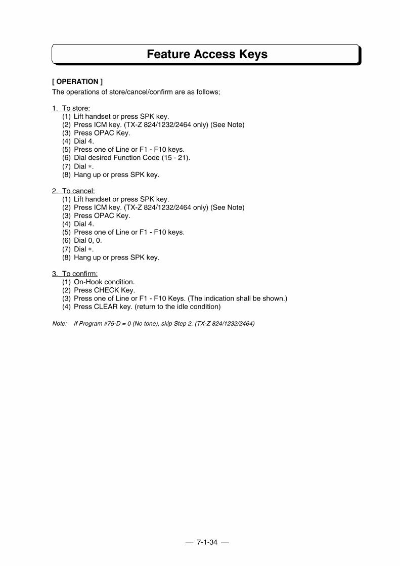
7-1-34
Feature Access Keys
[ OPERATION ]The operations of store/cancel/confirm are as follows;
1. To store:(1) Lift handset or press SPK key.(2) Press ICM key. (TX-Z 824/1232/2464 only) (See Note)(3) Press OPAC Key.(4) Dial 4.(5) Press one of Line or F1 - F10 keys.(6) Dial desired Function Code (15 - 21).(7) Dial ∗.(8) Hang up or press SPK key.
2. To cancel:(1) Lift handset or press SPK key.(2) Press ICM key. (TX-Z 824/1232/2464 only) (See Note)(3) Press OPAC Key.(4) Dial 4.(5) Press one of Line or F1 - F10 keys.(6) Dial 0, 0.(7) Dial ∗.(8) Hang up or press SPK key.
3. To confirm:(1) On-Hook condition.(2) Press CHECK Key.(3) Press one of Line or F1 - F10 Keys. (The indication shall be shown.)(4) Press CLEAR key. (return to the idle condition)
Note: If Program #75-D = 0 (No tone), skip Step 2. (TX-Z 824/1232/2464)
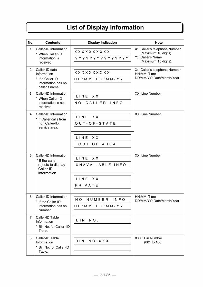
7-1-35
List of Display Information
No. Contents Display Indication Note
1 Caller-ID Information
* When Caller-IDinformation isreceived.
X X X X X X X X X X # # # # # #
Y Y Y Y Y Y Y Y Y Y Y Y Y Y Y
X: Caller's telephone Number(Maximum 10 digits)
Y: Caller's Name(Maximum 15 digits).
2 Caller-ID dataInformation
* If a Caller-IDinformation has nocaller's name.
X X X X X X X X X X # # # # # #
H H : M M # D D / M M / Y Y # #
X: Caller's telephone NumberHH:MM: TimeDD/MM/YY: Date/Month/Year
3 Caller-ID Information
* When Caller-IDinformation is notreceived.
L I N E # X X # # # # # # # # #
N O # C A L L E R # I N F O # #
XX: Line Number
L I N E # X X # # # # # # # # #
O U T - O F - S T A T E # # # #
4 Caller-ID Information
* If Caller calls fromnon Caller-IDservice area.
L I N E # X X # # # # # # # # #
O U T O F A R E A # # #
XX: Line Number
L I N E # X X # # # # # # # # #
U N A V A I L A B L E I N F O #
5 Caller-ID Information
* If the callerrejects to displayCaller-IDinformation
L I N E # X X # # # # # # # # #
P R I V A T E #
XX: Line Number
6 Caller-ID Information
* If the Caller-IDinformation has noNumber.
N O # N U M B E R # I N F O #
H H : M M # D D / M M / Y Y # #
HH:MM: TimeDD/MM/YY: Date/Month/Year
7 Caller-ID TableInformation
* Bin No. for Caller -IDTable.
B I N # N O . # # # # # # # # #
8 Caller-ID TableInformation
* Bin No. for Caller-IDTable.
B I N # N O . X X X # # # # # #XXX: Bin Number
(001 to 100)
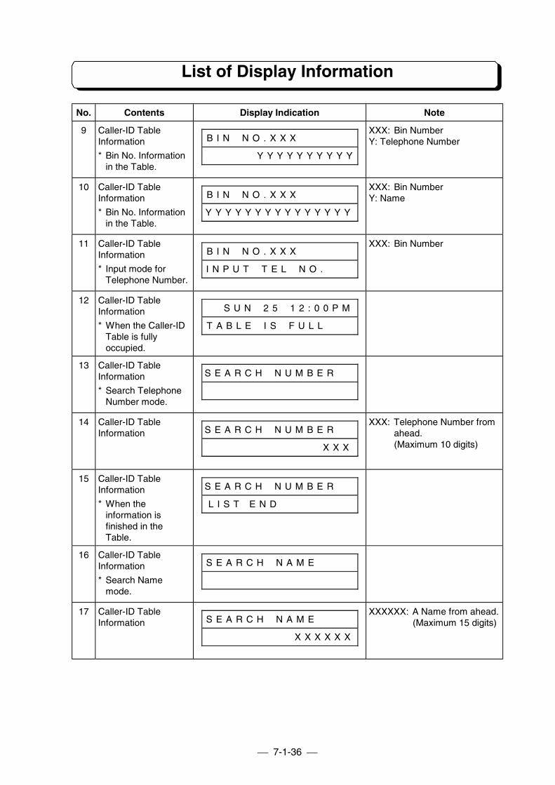
7-1-36
List of Display Information
No. Contents Display Indication Note
9 Caller-ID TableInformation
* Bin No. Informationin the Table.
B I N # N O . X X X # # # # # #
# # # # # # Y Y Y Y Y Y Y Y Y Y
XXX: Bin NumberY: Telephone Number
10 Caller-ID TableInformation
* Bin No. Informationin the Table.
B I N # N O . X X X # # # # # #
Y Y Y Y Y Y Y Y Y Y Y Y Y Y Y
XXX: Bin NumberY: Name
11 Caller-ID TableInformation
* Input mode forTelephone Number.
B I N # N O . X X X # # # # # #
I N P U T # T E L # N O . # # #
XXX: Bin Number
12 Caller-ID TableInformation
* When the Caller-IDTable is fullyoccupied.
# # S U N # 2 5 # 1 2 : 0 0 P M
T A B L E # I S # F U L L # # #
13 Caller-ID TableInformation
* Search TelephoneNumber mode.
S E A R C H # N U M B E R # #
14 Caller-ID TableInformation S E A R C H # N U M B E R # #
# # # # # # # # # # # # # X X X
XXX: Telephone Number fromahead.(Maximum 10 digits)
15 Caller-ID TableInformation
* When theinformation isfinished in theTable.
S E A R C H # N U M B E R # #
L I S T E N D # # # # # # # #
16 Caller-ID TableInformation
* Search Namemode.
S E A R C H # N A M E # # # #
17 Caller-ID TableInformation S E A R C H # N A M E # # # #
# # # # # # # # # # X X X X X X
XXXXXX: A Name from ahead.(Maximum 15 digits)
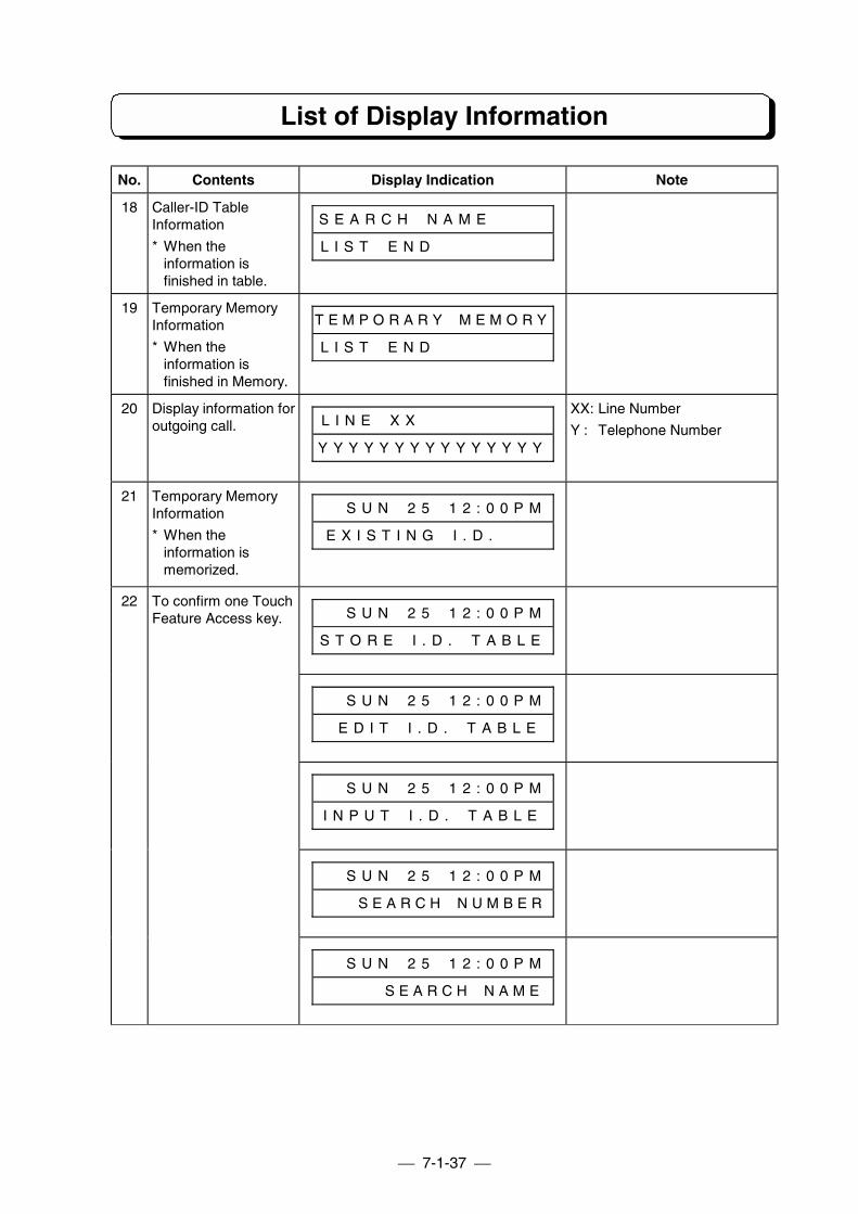
7-1-37
List of Display Information
No. Contents Display Indication Note
18 Caller-ID TableInformation
* When theinformation isfinished in table.
S E A R C H # N A M E # # # #
L I S T # E N D # # # # # # # #
19 Temporary MemoryInformation
* When theinformation isfinished in Memory.
T E M P O R A R Y # M E M O R Y
L I S T # E N D # # # # # # # #
20 Display information foroutgoing call. L I N E # X X # # # # # # # # #
Y Y Y Y Y Y Y Y Y Y Y Y Y Y Y
XX: Line Number
Y : Telephone Number
21 Temporary MemoryInformation
* When theinformation ismemorized.
# # S U N # 2 5 # 1 2 : 0 0 P M
E X I S T I N G # I . D . # # #
To confirm one TouchFeature Access key. # # S U N # 2 5 # 1 2 : 0 0 P M
S T O R E # I . D . # T A B L E
# # S U N # 2 5 # 1 2 : 0 0 P M
# E D I T # I . D . # T A B L E
# # S U N # 2 5 # 1 2 : 0 0 P M
I N P U T # I . D . # T A B L E
# # S U N # 2 5 # 1 2 : 0 0 P M
# # # S E A R C H # N U M B E R
22
# # S U N # 2 5 # 1 2 : 0 0 P M
# # # # # S E A R C H # N A M E
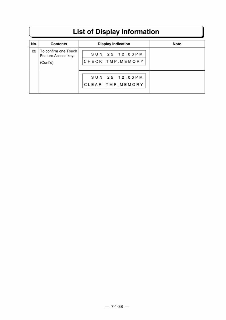
7-1-38
List of Display Information
No. Contents Display Indication Note
To confirm one TouchFeature Access key.
(Cont’d)
# # S U N # 2 5 # 1 2 : 0 0 P M
C H E C K # T M P . M E M O R Y
22
# # S U N # 2 5 # 1 2 : 0 0 P M
C L E A R # T M P . M E M O R Y
PART 7-2
OPTIONAL ITEM FOR TX-Z-308(FAX Transfer/DUD Unit)
PART 7-2-1
INSTALLATION
General DescriptionRequired ItemsInstallation of NX7E-3FAXU-A1 CardFax Machine InstallationInstallation NoticePreparation for Attendant MessageBasic Programming
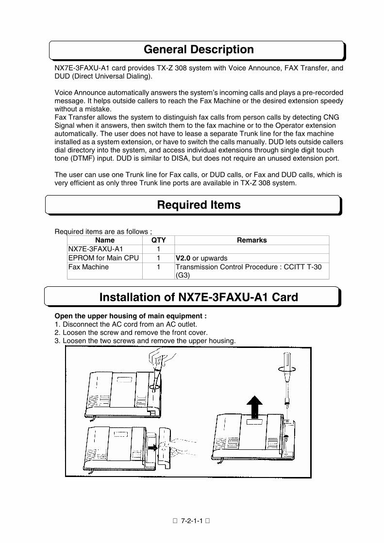
7-2-1-1
General DescriptionNX7E-3FAXU-A1 card provides TX-Z 308 system with Voice Announce, FAX Transfer, andDUD (Direct Universal Dialing).
Voice Announce automatically answers the system’s incoming calls and plays a pre-recordedmessage. It helps outside callers to reach the Fax Machine or the desired extension speedywithout a mistake.Fax Transfer allows the system to distinguish fax calls from person calls by detecting CNGSignal when it answers, then switch them to the fax machine or to the Operator extensionautomatically. The user does not have to lease a separate Trunk line for the fax machineinstalled as a system extension, or have to switch the calls manually. DUD lets outside callersdial directory into the system, and access individual extensions through single digit touchtone (DTMF) input. DUD is similar to DISA, but does not require an unused extension port.
The user can use one Trunk line for Fax calls, or DUD calls, or Fax and DUD calls, which isvery efficient as only three Trunk line ports are available in TX-Z 308 system.
Required Items
Required items are as follows ;Name QTY Remarks
NX7E-3FAXU-A1 1EPROM for Main CPU 1 V2.0 or upwardsFax Machine 1 Transmission Control Procedure : CCITT T-30
(G3)
Installation of NX7E-3FAXU-A1 CardOpen the upper housing of main equipment :1. Disconnect the AC cord from an AC outlet.2. Loosen the screw and remove the front cover.3. Loosen the two screws and remove the upper housing.
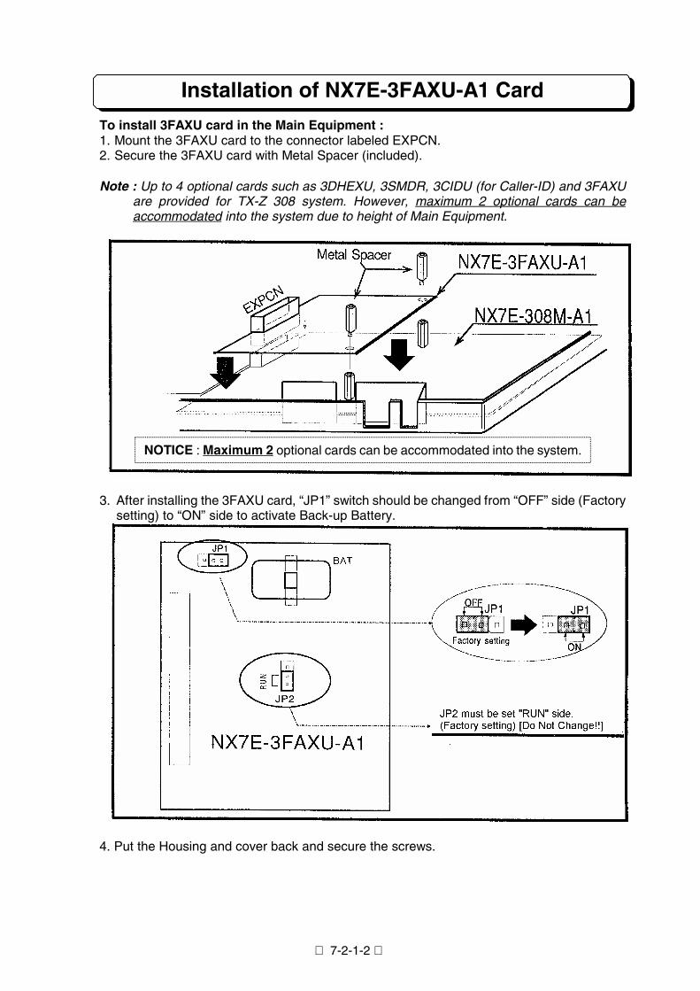
7-2-1-2
Installation of NX7E-3FAXU-A1 Card
To install 3FAXU card in the Main Equipment :1. Mount the 3FAXU card to the connector labeled EXPCN.2. Secure the 3FAXU card with Metal Spacer (included).
Note : Up to 4 optional cards such as 3DHEXU, 3SMDR, 3CIDU (for Caller-ID) and 3FAXUare provided for TX-Z 308 system. However, maximum 2 optional cards can beaccommodated into the system due to height of Main Equipment.
3. After installing the 3FAXU card, “JP1” switch should be changed from “OFF” side (Factorysetting) to “ON” side to activate Back-up Battery.
4. Put the Housing and cover back and secure the screws.
NOTICE : Maximum 2 optional cards can be accommodated into the system.
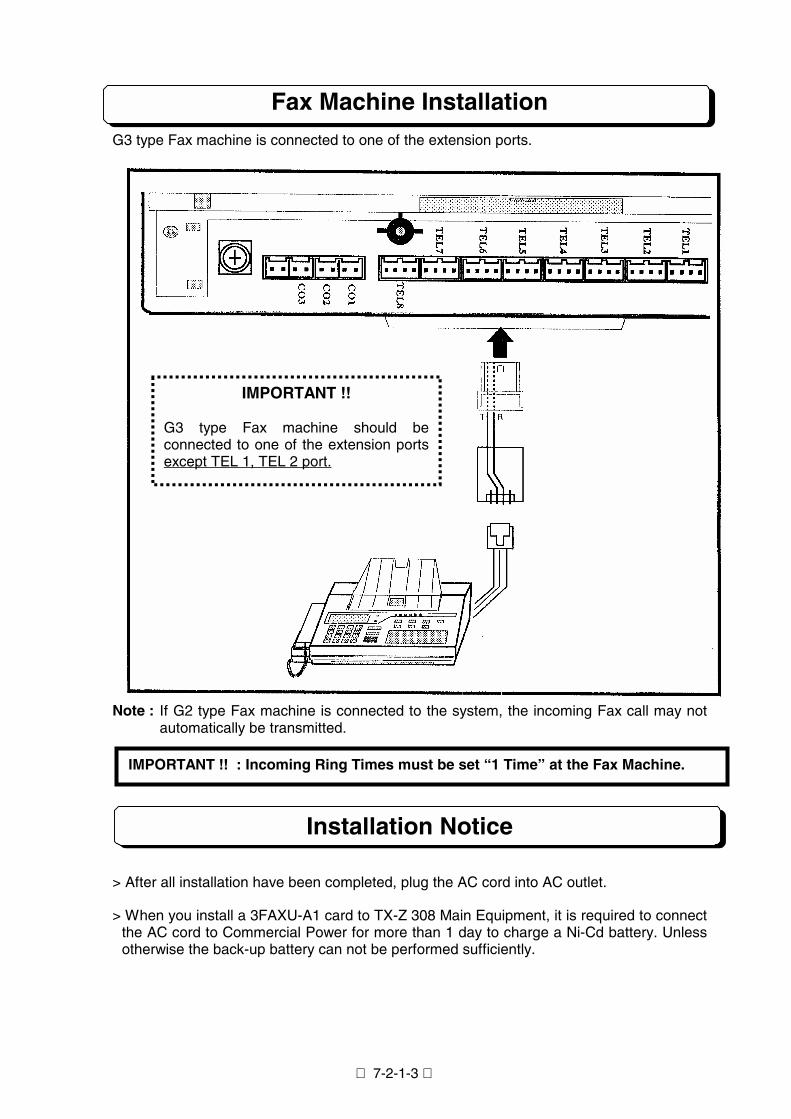
7-2-1-3
Fax Machine InstallationG3 type Fax machine is connected to one of the extension ports.
Note : If G2 type Fax machine is connected to the system, the incoming Fax call may notautomatically be transmitted.
Installation Notice
> After all installation have been completed, plug the AC cord into AC outlet.
> When you install a 3FAXU-A1 card to TX-Z 308 Main Equipment, it is required to connectthe AC cord to Commercial Power for more than 1 day to charge a Ni-Cd battery. Unlessotherwise the back-up battery can not be performed sufficiently.
IMPORTANT !! : Incoming Ring Times must be set “1 Time” at the Fax Machine.
IMPORTANT !!
G3 type Fax machine should beconnected to one of the extension portsexcept TEL 1, TEL 2 port.
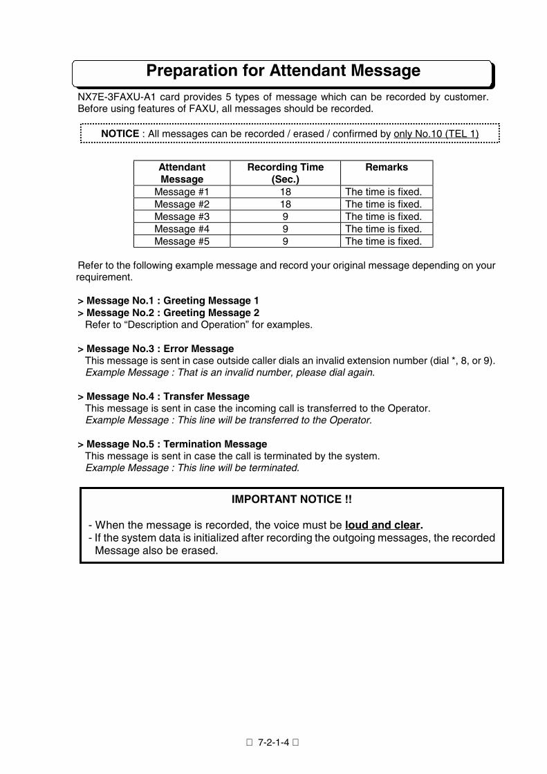
7-2-1-4
Preparation for Attendant MessageNX7E-3FAXU-A1 card provides 5 types of message which can be recorded by customer.Before using features of FAXU, all messages should be recorded.
AttendantMessage
Recording Time(Sec.)
Remarks
Message #1 18 The time is fixed.Message #2 18 The time is fixed.Message #3 9 The time is fixed.Message #4 9 The time is fixed.Message #5 9 The time is fixed.
Refer to the following example message and record your original message depending on yourrequirement.
> Message No.1 : Greeting Message 1> Message No.2 : Greeting Message 2
Refer to “Description and Operation” for examples.
> Message No.3 : Error MessageThis message is sent in case outside caller dials an invalid extension number (dial *, 8, or 9).Example Message : That is an invalid number, please dial again.
> Message No.4 : Transfer MessageThis message is sent in case the incoming call is transferred to the Operator.Example Message : This line will be transferred to the Operator.
> Message No.5 : Termination MessageThis message is sent in case the call is terminated by the system.Example Message : This line will be terminated.
NOTICE : All messages can be recorded / erased / confirmed by only No.10 (TEL 1)i
IMPORTANT NOTICE !!
- When the message is recorded, the voice must be loud and clear.- If the system data is initialized after recording the outgoing messages, the recorded
Message also be erased.
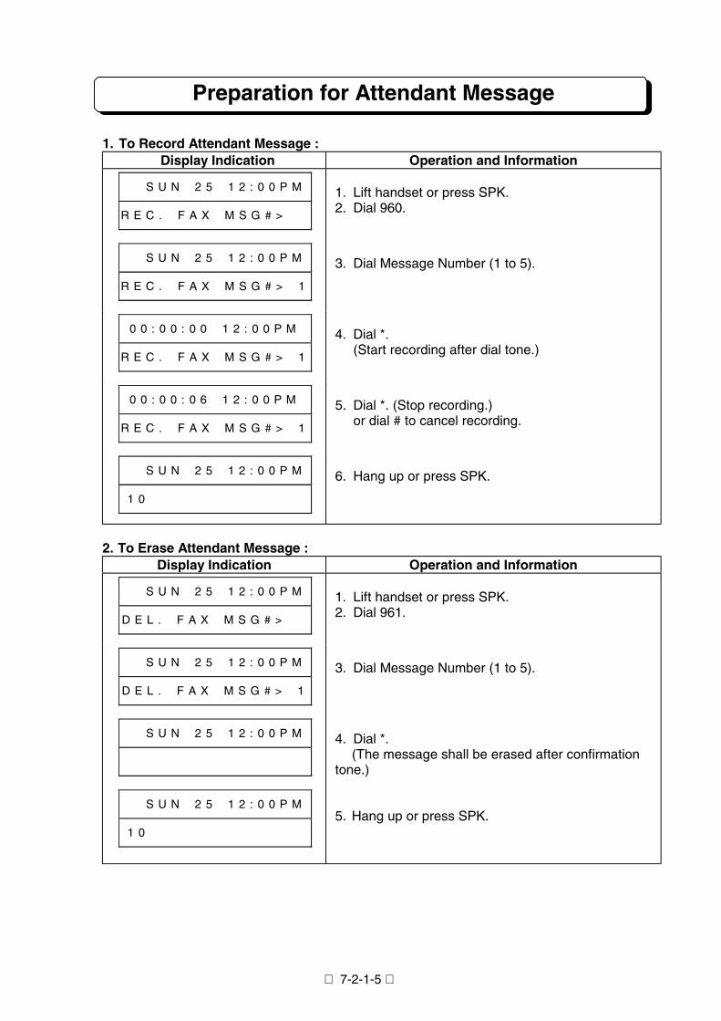
7-2-1-5
Preparation for Attendant Message
1. To Record Attendant Message :Display Indication Operation and Information
# # S U N # 2 5 # 1 2 : 0 0 P M
R E C . # F A X # M S G # > # #
1. Lift handset or press SPK.2. Dial 960.
# # S U N # 2 5 # 1 2 : 0 0 P M
R E C . # F A X # M S G # > # 1
3. Dial Message Number (1 to 5).
0 0 : 0 0 : 0 0 # 1 2 : 0 0 P M
R E C . # F A X # M S G # > # 1
4. Dial *.(Start recording after dial tone.)
0 0 : 0 0 : 0 6 # 1 2 : 0 0 P M
R E C . # F A X # M S G # > # 1
5. Dial *. (Stop recording.)or dial # to cancel recording.
# # S U N # 2 5 # 1 2 : 0 0 P M
1 0 # # # # # # # # # # # # # #
6. Hang up or press SPK.
2. To Erase Attendant Message :Display Indication Operation and Information
# # S U N # 2 5 # 1 2 : 0 0 P M
D E L . # F A X # M S G # > # #
1. Lift handset or press SPK.2. Dial 961.
# # S U N # 2 5 # 1 2 : 0 0 P M
D E L . # F A X # M S G # > # 1
3. Dial Message Number (1 to 5).
# # S U N # 2 5 # 1 2 : 0 0 P M
# # S U N # 2 5 # 1 2 : 0 0 P M
1 0 # # # # # # # # # # # # # #
4. Dial *.(The message shall be erased after confirmation
tone.)
5. Hang up or press SPK.
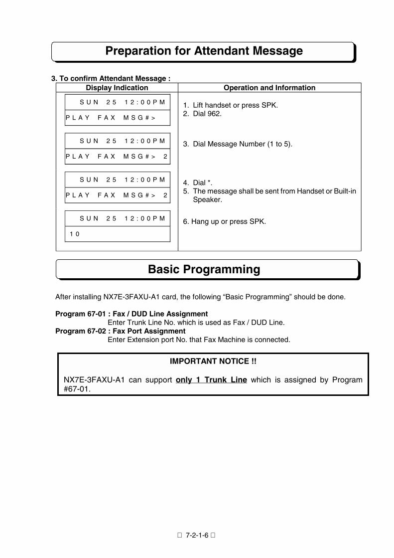
Preparation for Attendant Message
3. To confirm Attendant Message :Display Indication Operation and Information
# # S U N # 2 5 # 1 2 : 0 0 P M
P L A Y # F A X # M S G # > # #
1. Lift handset or press SPK.2. Dial 962.
# # S U N # 2 5 # 1 2 : 0 0 P M
P L A Y # F A X # M S G # > # 2
3. Dial Message Number (1 to 5).
# # S U N # 2 5 # 1 2 : 0 0 P M
P L A Y # F A X # M S G # > # 2
4. Dial *.5. The message shall be sent from Handset or Built-in
Speaker.
# # S U N # 2 5 # 1 2 : 0 0 P M
1 0 # # # # # # # # # # # v # #
6. Hang up or press SPK.
Basic Programming
After installing NX7E-3FAXU-A1 card, the following “Basic Programming” should be done.
Program 67-01 : Fax / DUD Line AssignmentEnter Trunk Line No. which is used as Fax / DUD Line.
Program 67-02 : Fax Port AssignmentEnter Extension port No. that Fax Machine is connected.
NX7E-3FAXU-A1 can suppo#67-01.
IMPORTANT NOTICE !!
rt only 1 Trunk Line which is assigned by Program
7-2-1-6
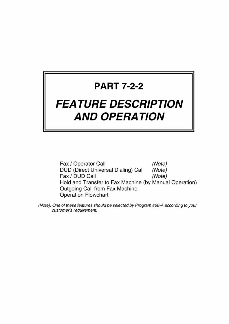
PART 7-2-2
FEATURE DESCRIPTIONAND OPERATION
Fax / Operator Call (Note)DUD (Direct Universal Dialing) Call (Note)Fax / DUD Call (Note)Hold and Transfer to Fax Machine (by Manual Operation)Outgoing Call from Fax MachineOperation Flowchart
(Note): One of these features should be selected by Program #68-A according to yourcustomer’s requirement.
7-2-2-1
Fax/Operator Call
Description
When there is an incoming call from outside caller on Fax / DUD Line which is assigned byProgram #67, the system automatically answers and sends Greeting Message (MessageNo.1) to outside caller.
<< Example Message for Message No.1 >>Thank you for calling. This is Nitsuko Corporation. If you wish to send your Fax Message,please press “START” key now. If you wish to talk, please wait a moment. Operator willanswer.
If “START” key is pressed by outside caller within defined time (Program #69-2) ...(CNG Signal* is detected)
The call shall automatically be transmitted to the connected Fax Machine. The outsidecaller (Fax Machine) can make communication with connected Fax Machine.
If assigned time (Program #69-2) has passed ... (CNG Signal* is not detected)Transfer Message (Message No.4) is sent to outside caller and this call shall automaticallybe transferred to the Operator (No.10 Extension).
(*) CNG Signal may be sent from outside caller (Fax Machine)
Note 1 : Only Operator’s extension (No.10) shall ring.Note 2 : Other extension users can pickup this call by using “Call Pickup” operation or press
flashing Line Key.Note 3 : In case the Operator is in busy status, muted ringing tone is sent from built-in
speaker and a Line key flashes green at Operator’s extension.Note 4 : If nobody answers within assigned time (Program #69-4), Termination Message
(Message No.5) is sent to outside caller and this call shall be terminated.Note 5 : In case the connected Fax Machine is in busy status, the call shall be terminated.Note 6 : Some old type Fax Machine may not send CNG Signal. If Operator answers and
hears no sound, this call shall be transferred to the Fax Machine by manualoperation.
.Related Programming
Program #68-A : Line Type (should be set to “0”)Program #68-B : When CNG Signal is not detected (should be set to “1”)Program #69-2 : CNG Signal Waiting TimeProgram #69-4 : SLT/FAX Calling Time
7-2-2-2
DUD (Direct Universal Dialing) CallDescription
NX7E-3FAXU-A1 card also provides DUD with Voice Announce feature.
When there is an incoming call from outside caller on Fax / DUD Line (assigned by Program#67), the system automatically answers and sends Greeting Message (Message No.2) tooutside caller. The outside caller can access the desired extension by dialing 1 digit (0 to 7for Extension No.10 to 17).
<< Example Message for Message No.2 >>Thank you for calling. This is Nitsuko Corporation. Please dial the desired extension No.“1” to “7”, or dial “0” to Operator.
In case the desired extension is in idle status ...Only dialed extension shall ring. However, the other extension user can pickup this call byusing “Call Pickup” operation or press flashing Line Key.
In case nobody answers within assigned time (Program #69-4) ...Termination Message (Message No.5) is sent to outside caller and this call shall beterminated.
In case the desired extension is in busy status ...There are 3 cases as follows ;[Case 1] Terminate immediately (Program #68-C : 0)
Termination Message (Message No.5) is sent to outside caller and this call shall beterminated.
[Case 2] Transfer to the Operator (Program #68-C : 1)Transfer Message (Message No.4) is sent to outside caller and this call shall betransferred to the Operator.
[Case 3] Return to previous mode (Program #68-C : 2)Greeting Message (Message No.2) is sent to outside caller again and anotherextension No. can be dialed. If the extension user is also in busy status,Termination Message (Message No.5) is sent to outside caller and this call shallautomatically be terminated.
In case of no dialing by outside caller ...Same as “In case the desired extension is in busy status ...”.
Important Notice : 3FAXU-A1 card does not support current DISA feature.
7-2-2-3
DUD (Direct Universal Dialing) Call
Information
This feature also provides following additional functions.
DUD Call at Night ModeIn case there is an incoming call from outside caller on Fax / DUD Line while the system isplaced in Night Service, the system automatically answers and sends Night Message(Message No.1) to outside caller.
<< Example Message for Message No.1 >>Thank you for calling. This is Nitsuko Corporation. Our office is closed now. Please callback again.
After sending the above message and assigned time (Program #69-3) has passed,Termination Message (Message No.5) is sent to the outside caller and this incoming callshall automatically be terminated.
Delayed DUDThis function is provided by Program #69-1 assignment. When there is an incoming call onFax / DUD line, this call is an normal incoming call (the extension assigned by Program #7may ring.). If nobody answers within pre-programmed period (Program #69-1), this callshall be in DUD mode.
Fax CallIf the outside caller want to send Fax data, this call shall be transferred to the connectedFax Machine by dialing “#” instead of dialing extension No.. Fax communication will startwhen START key is pressed by outside caller after the connected Fax machine answers.
Related Programming
Program #7 : Incoming Trunk Access / AudibleProgram #68-A : Line Type (should be set to “1”)Program #68-C : When extension is busyProgram #69-1 : Automatic Answer TimerProgram #69-3 : DTMF Signal Waiting TimeProgram #69-4 : SLT/FAX Calling Time
7-2-2-4
Fax / DUD (Direct Universal Dialing) Call
Description
When there is an incoming call from outside caller on Fax / DUD Line (which is assigned byProgram #67), the system automatically answers and sends Greeting Message (MessageNo.1) to outside caller.
<< Example Message for Message No.1 >>Thank you for calling. This is Nitsuko Corporation. If you wish to send your Fax Message,please press “START” key now. If you wish to talk, please wait a moment.
If “START” key is pressed by outside caller within defined time (Program #69-2) ...(CNG Signal* is detected)
The call shall automatically be transmitted to the connected Fax Machine. The outsidecaller (Fax Machine) can make communication with connected Fax Machine.
If assigned time (Program #69-2) has passed ... (CNG Signal* is detected)Next Greeting Message (Message No.2) is sent to outside caller. The outside caller canaccess to the desired extension by dialing 1 digit. (0 to 7 for Extension No.10 to 17, and #for Fax Machine)
<< Example Message for Message No.2 >>Please dial the desired extension No. “1” to “7”, or dial “0” to Operator. (or “#” to Fax
Machine)
For the details of DUD features, please refer to “DUD Call”.
Related Programming
Program #68-A : Line Type (should be set to “2”)Program #68-C : When extension is busyProgram #69-1 : Automatic Answer TimeProgram #69-2 : CNG Signal Waiting TimeProgram #69-3 : DTMF Signal Waiting TimeProgram #69-4 : SLT/FAX Calling Time
7-2-2-5
Hold and Transfer to Fax Machine
Description
In case an extension user answers to Fax call due to some reason (miss-operation by theoutside caller, etc...), this call can be transferred to the connected Fax Machine by manualoperation.
Related Programming
None
Operation
< Key Telephone >1. Answer an incoming call. (CNG Signal may be heard.)2. Press TRFR key.
Confirmation Tone (short beep tone) shall be heard if transmission is successful. IfError Tone (200ms ON/OFF : 3 times) is heard, transmission is failed due to somereason (Fax Machine is in busy status, etc...).
3. Hang up.
< Single Line Telephone >1. Answer an incoming call. (CNG Signal may be heard.)2. Hookflash.3. Dial the extension No. of Fax Machine and hang up.
Outgoing Call from Fax Machine
Description
The Fax data can be sent from the connected Fax Machine to outside Fax Machine withoutdialing a trunk access code.
Related Programming
Program #75-C : Automatic Trunk Access (should be set to “1”)
Operation
1. Go off-hook at Fax Machine. (Dial Tone from Exchange shall be heard.)2. Dial outside Fax Number.3. Press START key after the outside Fax Machine answers.
(Note) : This feature disables the Fax Machine to make intercom outgoing calls.
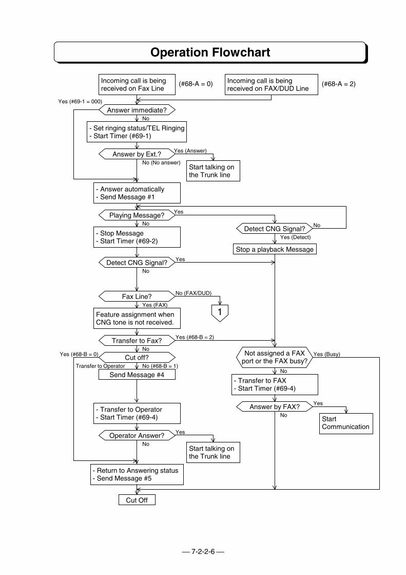
7-2-2-6
Operation Flowchart
Start talking onthe Trunk line
StartCommunication
Start talking onthe Trunk line
Stop a playback Message
Send Message #4
Cut Off
Incoming call is beingreceived on FAX/DUD Line
Incoming call is beingreceived on Fax Line
- Set ringing status/TEL Ringing- Start Timer (#69-1)
(#68-A = 2)(#68-A = 0)
Yes (#69-1 = 000)
Yes (#68-B = 0)
No
Yes (Answer)
NoNo
Yes (Detect)
No
Yes (Busy)No
Transfer to Operator No (#68-B = 1)No
Yes
No
Yes
No
No (No answer)
Yes
Yes
Yes (FAX)
- Answer automatically- Send Message #1
- Stop Message- Start Timer (#69-2)
Feature assignment whenCNG tone is not received.
- Return to Answering status- Send Message #5
- Transfer to FAX- Start Timer (#69-4)
- Transfer to Operator- Start Timer (#69-4)
Operator Answer?
Cut off?
Transfer to Fax?
Fax Line?
Detect CNG Signal?
Playing Message?
Answer by Ext.?
Answer immediate?
Detect CNG Signal?
Not assigned a FAXport or the FAX busy?
Answer by FAX?
1
No (FAX/DUD)
Yes (#68-B = 2)
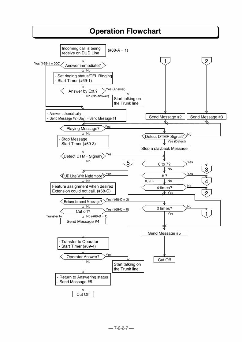
7-2-2-7
Operation Flowchart
Send Message #3
Start talking onthe Trunk line
Start talking onthe Trunk line
Send Message #2
Stop a playback Message
Send Message #5
Send Message #4
Cut Off
Cut Off
Incoming call is beingreceive on DUD Line
- Set ringing status/TEL Ringing- Start Timer (#69-1)
(#68-A = 1)
Yes (#69-1 = 000)
No
Yes (Answer)
No
Yes
No
No
Yes
Yes
Yes
No
No
No
Yes (Detect)
No
No
Transfer to No (#68-B = 1)
Yes
No
No (No answer)
Yes
Yes
No
- Answer automatically- Send Message #2 (Day), - Send Message #1
- Stop Message- Start Timer (#69-3)
Feature assignment when desiredExtension could not call. (#68-C)
- Return to Answering status- Send Message #5
- Transfer to Operator- Start Timer (#69-4)
Operator Answer?
Cut off?
Return to send Message?
DUD Line With Night mode?
Detect DTMF Signal?
Playing Message?
Answer by Ext.?
Answer immediate?
Detect DTMF Signal?
1
Yes
8, 9, ∗
Yes (#68-C = 2)
Yes (#68-C = 0)
2
0 to 7?
# ?
4 times?
2 times?
3
4
2
1
5
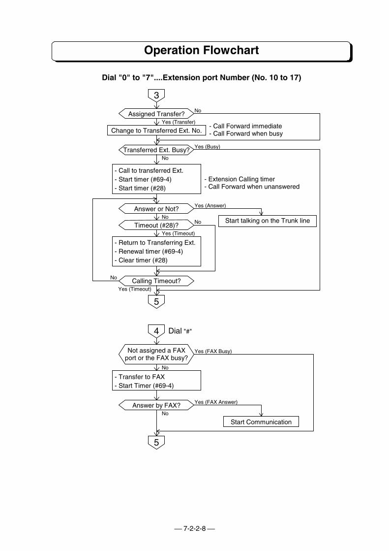
7-2-2-8
Operation Flowchart
Dial "0" to "7"....Extension port Number (No. 10 to 17)
Change to Transferred Ext. No.
Start talking on the Trunk line
- Call Forward immediate- Call Forward when busy
- Extension Calling timer- Call Forward when unanswered
- Call to transferred Ext.- Start timer (#69-4)- Start timer (#28)
- Return to Transferring Ext.- Renewal timer (#69-4)- Clear timer (#28)
No
No
Yes (Transfer)
Yes (Busy)
Assigned Transfer?
3
5
Transferred Ext. Busy?
Answer or Not?
Timeout (#28)?
Calling Timeout?
NoNo
No
Yes (Answer)
Yes (Timeout)
Yes (Timeout)
Dial "#"
Start Communication
- Transfer to FAX- Start Timer (#69-4)
No
No
4
Not assigned a FAXport or the FAX busy?
Answer by FAX?
5
Yes (FAX Busy)
Yes (FAX Answer)
PART 7-3
OPTIONAL ITEMFOR TX-Z 1232/2464
(Voice Announce/Record Unit)
PART 7-3-1
OUTLINE OF VAU
Introduction
VAU Capacity
How to Record VAU Message
How to Erase VAU Message
How to Confirm VAU Message
Table of VAU Message
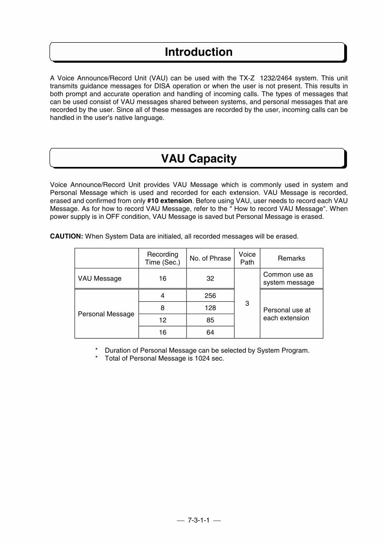
7-3-1-1
Introduction
A Voice Announce/Record Unit (VAU) can be used with the TX-Z 1232/2464 system. This unittransmits guidance messages for DISA operation or when the user is not present. This results inboth prompt and accurate operation and handling of incoming calls. The types of messages thatcan be used consist of VAU messages shared between systems, and personal messages that arerecorded by the user. Since all of these messages are recorded by the user, incoming calls can behandled in the user's native language.
VAU Capacity
Voice Announce/Record Unit provides VAU Message which is commonly used in system andPersonal Message which is used and recorded for each extension. VAU Message is recorded,erased and confirmed from only #10 extension. Before using VAU, user needs to record each VAUMessage. As for how to record VAU Message, refer to the " How to record VAU Message". Whenpower supply is in OFF condition, VAU Message is saved but Personal Message is erased.
CAUTION: When System Data are initialed, all recorded messages will be erased.
RecordingTime (Sec.)
No. of PhraseVoicePath
Remarks
VAU Message 16 32Common use assystem message
4 256
8 128
12 85Personal Message
16 64
3Personal use ateach extension
* Duration of Personal Message can be selected by System Program.* Total of Personal Message is 1024 sec.
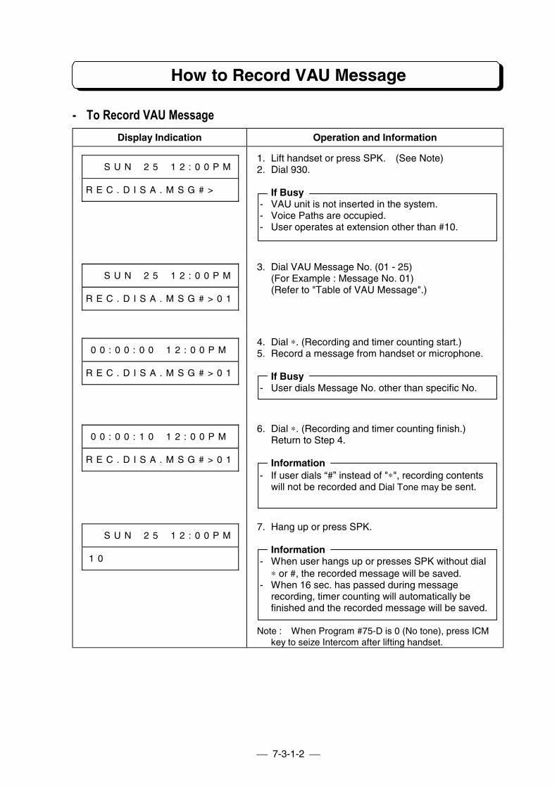
7-3-1-2
How to Record VAU Message
- To Record VAU MessageDisplay Indication Operation and Information
# # S U N # 2 5 # 1 2 : 0 0 P M
R E C . D I S A . M S G # > # #
1. Lift handset or press SPK. (See Note)2. Dial 930.
If Busy- VAU unit is not inserted in the system.- Voice Paths are occupied.- User operates at extension other than #10.
# # S U N # 2 5 # 1 2 : 0 0 P M
R E C . D I S A . M S G # > 0 1
3. Dial VAU Message No. (01 - 25)(For Example : Message No. 01)(Refer to "Table of VAU Message".)
0 0 : 0 0 : 0 0 # 1 2 : 0 0 P M
R E C . D I S A . M S G # > 0 1
4. Dial ∗. (Recording and timer counting start.)5. Record a message from handset or microphone.
If Busy- User dials Message No. other than specific No.
0 0 : 0 0 : 1 0 # 1 2 : 0 0 P M
R E C . D I S A . M S G # > 0 1
6. Dial ∗. (Recording and timer counting finish.)Return to Step 4.
Information- If user dials “#” instead of "∗", recording contents
will not be recorded and Dial Tone may be sent.
# # S U N # 2 5 # 1 2 : 0 0 P M
1 0 # # # # # # # # # # # # # #
7. Hang up or press SPK.
Information- When user hangs up or presses SPK without dial
∗ or #, the recorded message will be saved.- When 16 sec. has passed during message
recording, timer counting will automatically befinished and the recorded message will be saved.
Note : When Program #75-D is 0 (No tone), press ICMkey to seize Intercom after lifting handset.
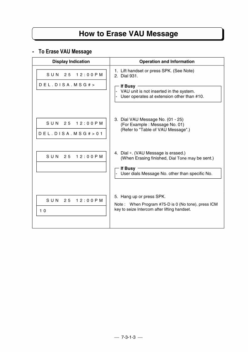
7-3-1-3
How to Erase VAU Message
- To Erase VAU MessageDisplay Indication Operation and Information
# # S U N # 2 5 # 1 2 : 0 0 P M
D E L . D I S A . M S G # > # #
1. Lift handset or press SPK. (See Note)2. Dial 931.
If Busy- VAU unit is not inserted in the system.- User operates at extension other than #10.
# # S U N # 2 5 # 1 2 : 0 0 P M
D E L . D I S A . M S G # > 0 1
3. Dial VAU Message No. (01 - 25)(For Example : Message No. 01)(Refer to "Table of VAU Message".)
# # S U N # 2 5 # 1 2 : 0 0 P M4. Dial ∗. (VAU Message is erased.)
(When Erasing finished, Dial Tone may be sent.)
If Busy- User dials Message No. other than specific No.
# # S U N # 2 5 # 1 2 : 0 0 P M
1 0 # # # # # # # # # # # # # #
5. Hang up or press SPK.
Note : When Program #75-D is 0 (No tone), press ICMkey to seize Intercom after lifting handset.
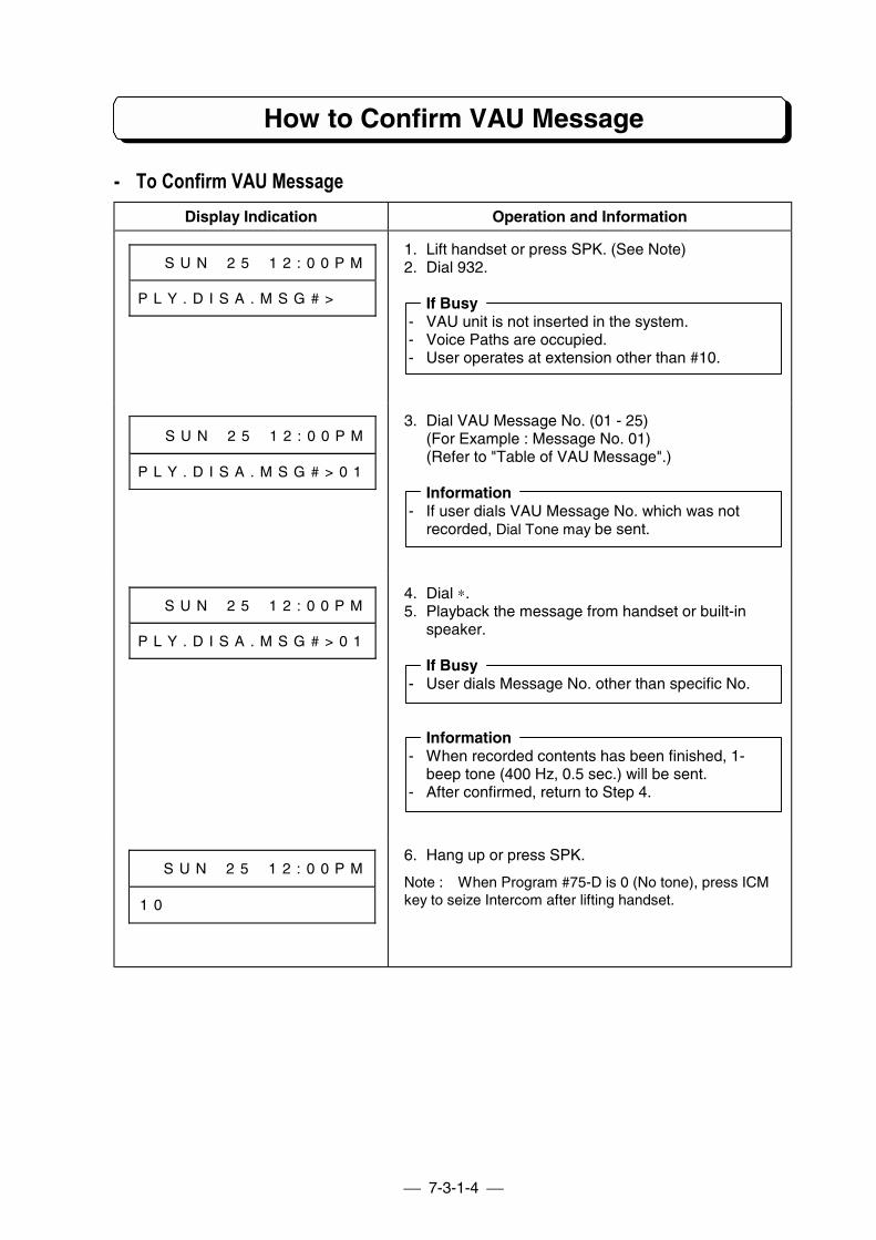
7-3-1-4
How to Confirm VAU Message
- To Confirm VAU MessageDisplay Indication Operation and Information
# # S U N # 2 5 # 1 2 : 0 0 P M
P L Y . D I S A . M S G # > # #
1. Lift handset or press SPK. (See Note)2. Dial 932.
If Busy- VAU unit is not inserted in the system.- Voice Paths are occupied.- User operates at extension other than #10.
# # S U N # 2 5 # 1 2 : 0 0 P M
P L Y . D I S A . M S G # > 0 1
3. Dial VAU Message No. (01 - 25)(For Example : Message No. 01)(Refer to "Table of VAU Message".)
Information- If user dials VAU Message No. which was not
recorded, Dial Tone may be sent.
# # S U N # 2 5 # 1 2 : 0 0 P M
P L Y . D I S A . M S G # > 0 1
4. Dial ∗.5. Playback the message from handset or built-in
speaker.
If Busy- User dials Message No. other than specific No.
Information- When recorded contents has been finished, 1-
beep tone (400 Hz, 0.5 sec.) will be sent.- After confirmed, return to Step 4.
# # S U N # 2 5 # 1 2 : 0 0 P M
1 0 # # # # # # # # # # # # # #
6. Hang up or press SPK.
Note : When Program #75-D is 0 (No tone), press ICMkey to seize Intercom after lifting handset.
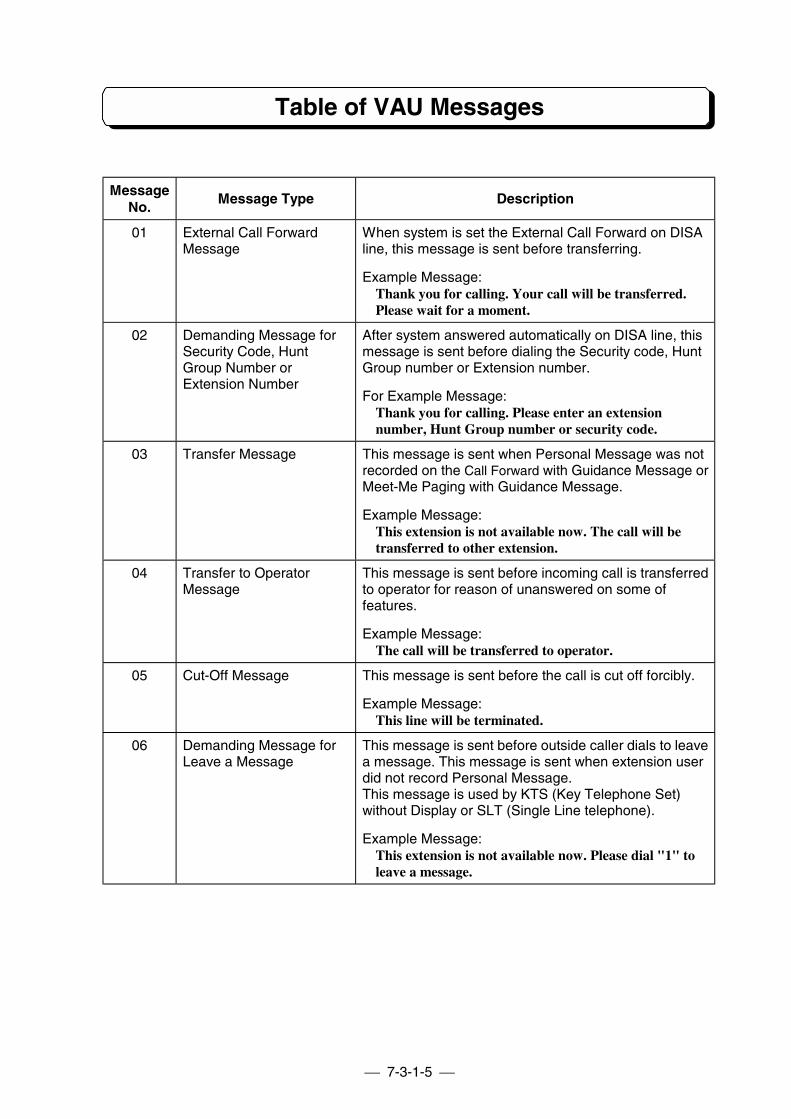
7-3-1-5
Table of VAU Messages
MessageNo.
Message Type Description
01 External Call ForwardMessage
When system is set the External Call Forward on DISAline, this message is sent before transferring.
Example Message:Thank you for calling. Your call will be transferred.Please wait for a moment.
02 Demanding Message forSecurity Code, HuntGroup Number orExtension Number
After system answered automatically on DISA line, thismessage is sent before dialing the Security code, HuntGroup number or Extension number.
For Example Message:Thank you for calling. Please enter an extensionnumber, Hunt Group number or security code.
03 Transfer Message This message is sent when Personal Message was notrecorded on the Call Forward with Guidance Message orMeet-Me Paging with Guidance Message.
Example Message:This extension is not available now. The call will betransferred to other extension.
04 Transfer to OperatorMessage
This message is sent before incoming call is transferredto operator for reason of unanswered on some offeatures.
Example Message:The call will be transferred to operator.
05 Cut-Off Message This message is sent before the call is cut off forcibly.
Example Message:This line will be terminated.
06 Demanding Message forLeave a Message
This message is sent before outside caller dials to leavea message. This message is sent when extension userdid not record Personal Message.This message is used by KTS (Key Telephone Set)without Display or SLT (Single Line telephone).
Example Message:This extension is not available now. Please dial "1" toleave a message.
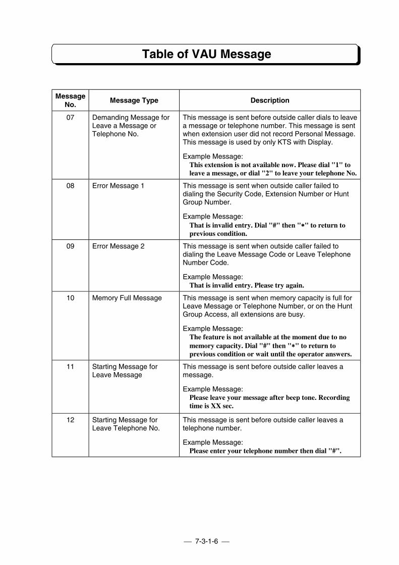
7-3-1-6
Table of VAU Message
MessageNo.
Message Type Description
07 Demanding Message forLeave a Message orTelephone No.
This message is sent before outside caller dials to leavea message or telephone number. This message is sentwhen extension user did not record Personal Message.This message is used by only KTS with Display.
Example Message:This extension is not available now. Please dial "1" toleave a message, or dial "2" to leave your telephone No.
08 Error Message 1 This message is sent when outside caller failed todialing the Security Code, Extension Number or HuntGroup Number.
Example Message:That is invalid entry. Dial "#" then "∗∗∗∗" to return toprevious condition.
09 Error Message 2 This message is sent when outside caller failed todialing the Leave Message Code or Leave TelephoneNumber Code.
Example Message:That is invalid entry. Please try again.
10 Memory Full Message This message is sent when memory capacity is full forLeave Message or Telephone Number, or on the HuntGroup Access, all extensions are busy.
Example Message:The feature is not available at the moment due to nomemory capacity. Dial "#" then "∗∗∗∗" to return toprevious condition or wait until the operator answers.
11 Starting Message forLeave Message
This message is sent before outside caller leaves amessage.
Example Message:Please leave your message after beep tone. Recordingtime is XX sec.
12 Starting Message forLeave Telephone No.
This message is sent before outside caller leaves atelephone number.
Example Message:Please enter your telephone number then dial "#".
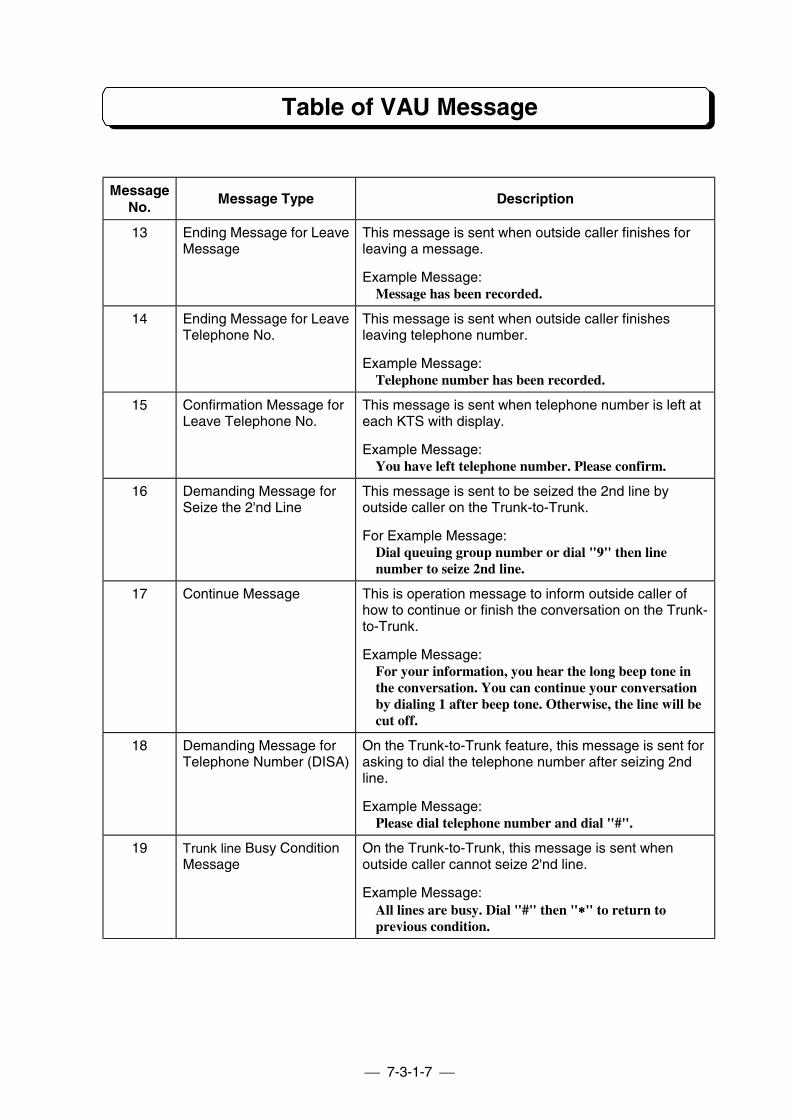
7-3-1-7
Table of VAU Message
MessageNo.
Message Type Description
13 Ending Message for LeaveMessage
This message is sent when outside caller finishes forleaving a message.
Example Message:Message has been recorded.
14 Ending Message for LeaveTelephone No.
This message is sent when outside caller finishesleaving telephone number.
Example Message:Telephone number has been recorded.
15 Confirmation Message forLeave Telephone No.
This message is sent when telephone number is left ateach KTS with display.
Example Message:You have left telephone number. Please confirm.
16 Demanding Message forSeize the 2'nd Line
This message is sent to be seized the 2nd line byoutside caller on the Trunk-to-Trunk.
For Example Message:Dial queuing group number or dial "9" then linenumber to seize 2nd line.
17 Continue Message This is operation message to inform outside caller ofhow to continue or finish the conversation on the Trunk-to-Trunk.
Example Message:For your information, you hear the long beep tone inthe conversation. You can continue your conversationby dialing 1 after beep tone. Otherwise, the line will becut off.
18 Demanding Message forTelephone Number (DISA)
On the Trunk-to-Trunk feature, this message is sent forasking to dial the telephone number after seizing 2ndline.
Example Message:Please dial telephone number and dial "#".
19 Trunk line Busy ConditionMessage
On the Trunk-to-Trunk, this message is sent whenoutside caller cannot seize 2'nd line.
Example Message:All lines are busy. Dial "#" then "∗∗∗∗" to return toprevious condition.
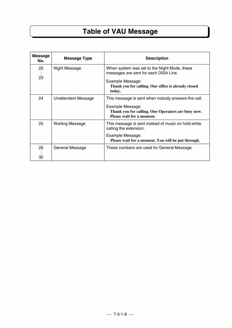
7-3-1-8
Table of VAU Message
MessageNo.
Message Type Description
20
23
Night Message When system was set to the Night Mode, thesemessages are sent for each DISA Line.
Example Message:Thank you for calling. Our office is already closedtoday.
24 Unattendant Message This message is sent when nobody answers the call.
Example Message:Thank you for calling. Our Operators are busy now.Please wait for a moment.
25 Waiting Message This message is sent instead of music on hold.whilecalling the extension.
Example Message: Please wait for a moment. You will be put through.
26
32
General Message These numbers are used for General Message.
PART 7-3-2
INSTALLATION OF VAU
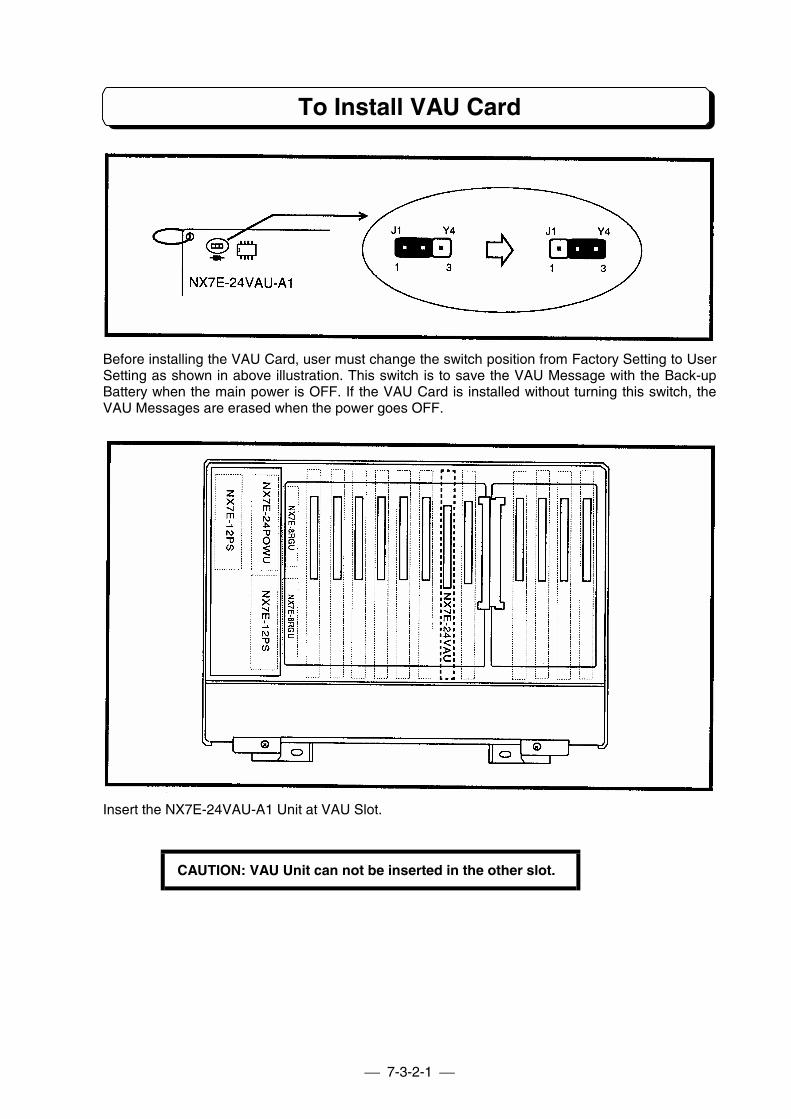
7-3-2-1
To Install VAU Card
Before installing the VAU Card, user must change the switch position from Factory Setting to UserSetting as shown in above illustration. This switch is to save the VAU Message with the Back-upBattery when the main power is OFF. If the VAU Card is installed without turning this switch, theVAU Messages are erased when the power goes OFF.
Insert the NX7E-24VAU-A1 Unit at VAU Slot.
CAUTION: VAU Unit can not be inserted in the other slot.
PART 7-3-3
FEATURE DESCRIPTIONAND OPERATION
Table of Contents
Features on DISA ............................................................................................................... 7-3-3-1
DISA with Automated Attendant ....................................................................7-3-3-1Leave a Message (from outside) ...................................................................7-3-3-2Leave a Telephone Number ..........................................................................7-3-3-8External Call Forward to Mobile Phone.......................................................7-3-3-12Call Information to Pager .............................................................................7-3-3-13Message Playback from Outside.................................................................7-3-3-14Waiting Message .........................................................................................7-3-3-14
Features on Transfer.....................................................................................7-3-3-15
Call Forward with Guidance Message.........................................................7-3-3-15Meet-Me Paging with Guidance Message...................................................7-3-3-18
Other Features ................................................................................................7-3-3-24
General Message.........................................................................................7-3-3-24Unattendant Message (Automated Attendant for normal incoming)...........7-3-3-29
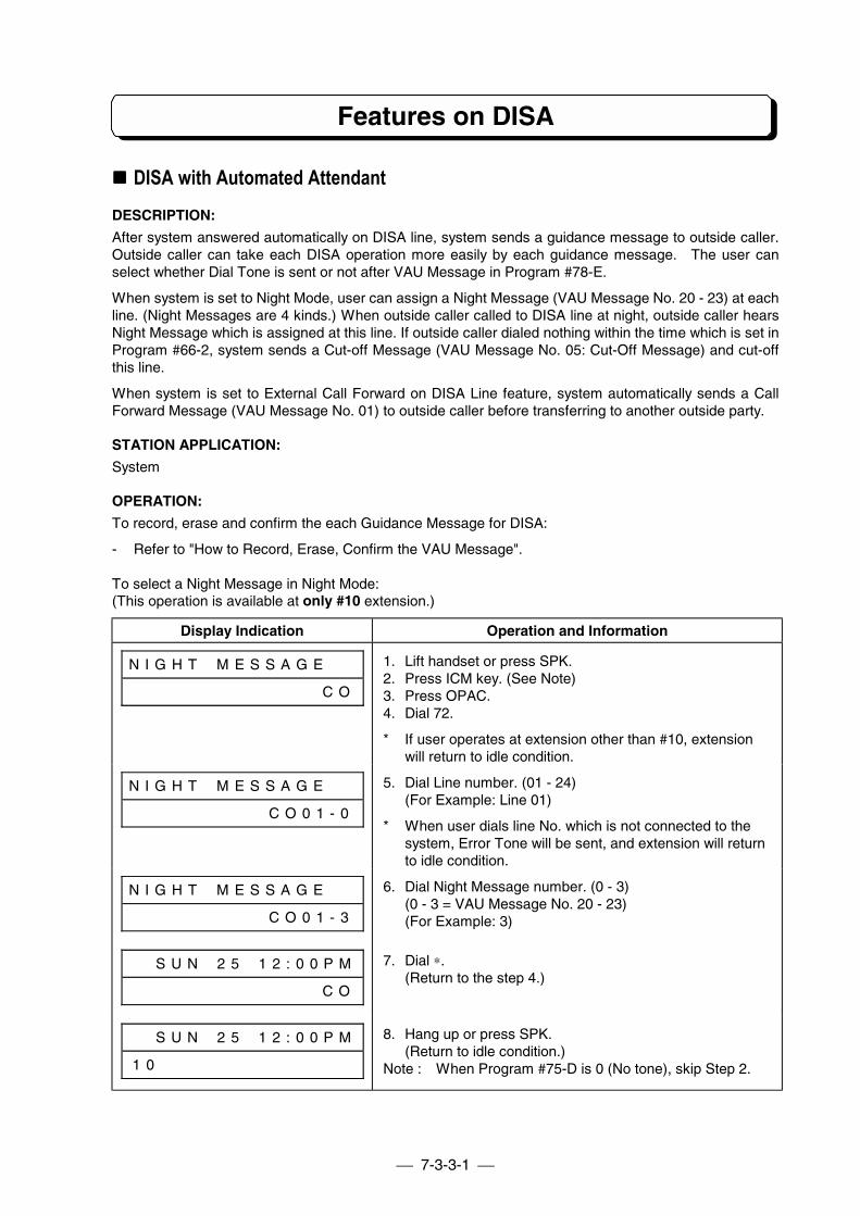
7-3-3-1
Features on DISA
!!!! DISA with Automated AttendantDESCRIPTION:
After system answered automatically on DISA line, system sends a guidance message to outside caller.Outside caller can take each DISA operation more easily by each guidance message. The user canselect whether Dial Tone is sent or not after VAU Message in Program #78-E.
When system is set to Night Mode, user can assign a Night Message (VAU Message No. 20 - 23) at eachline. (Night Messages are 4 kinds.) When outside caller called to DISA line at night, outside caller hearsNight Message which is assigned at this line. If outside caller dialed nothing within the time which is set inProgram #66-2, system sends a Cut-off Message (VAU Message No. 05: Cut-Off Message) and cut-offthis line.
When system is set to External Call Forward on DISA Line feature, system automatically sends a CallForward Message (VAU Message No. 01) to outside caller before transferring to another outside party.
STATION APPLICATION:
System
OPERATION:
To record, erase and confirm the each Guidance Message for DISA:
- Refer to "How to Record, Erase, Confirm the VAU Message".
To select a Night Message in Night Mode:(This operation is available at only #10 extension.)
Display Indication Operation and Information
N I G H T # M E S S A G E # #
# # # # # # # # # # # # # # C O
1. Lift handset or press SPK.2. Press ICM key. (See Note)3. Press OPAC.4. Dial 72.
* If user operates at extension other than #10, extensionwill return to idle condition.
N I G H T # M E S S A G E # #
# # # # # # # # # # C O 0 1 - 0
5. Dial Line number. (01 - 24)(For Example: Line 01)
* When user dials line No. which is not connected to thesystem, Error Tone will be sent, and extension will returnto idle condition.
N I G H T # M E S S A G E # #
# # # # # # # # # # C O 0 1 - 3
6. Dial Night Message number. (0 - 3)(0 - 3 = VAU Message No. 20 - 23)(For Example: 3)
# # S U N # 2 5 # 1 2 : 0 0 P M
# # # # # # # # # # # # # # C O
7. Dial ∗.(Return to the step 4.)
# # S U N # 2 5 # 1 2 : 0 0 P M
1 0 # # # # # # # # # # # # # #
8. Hang up or press SPK.(Return to idle condition.)
Note : When Program #75-D is 0 (No tone), skip Step 2.
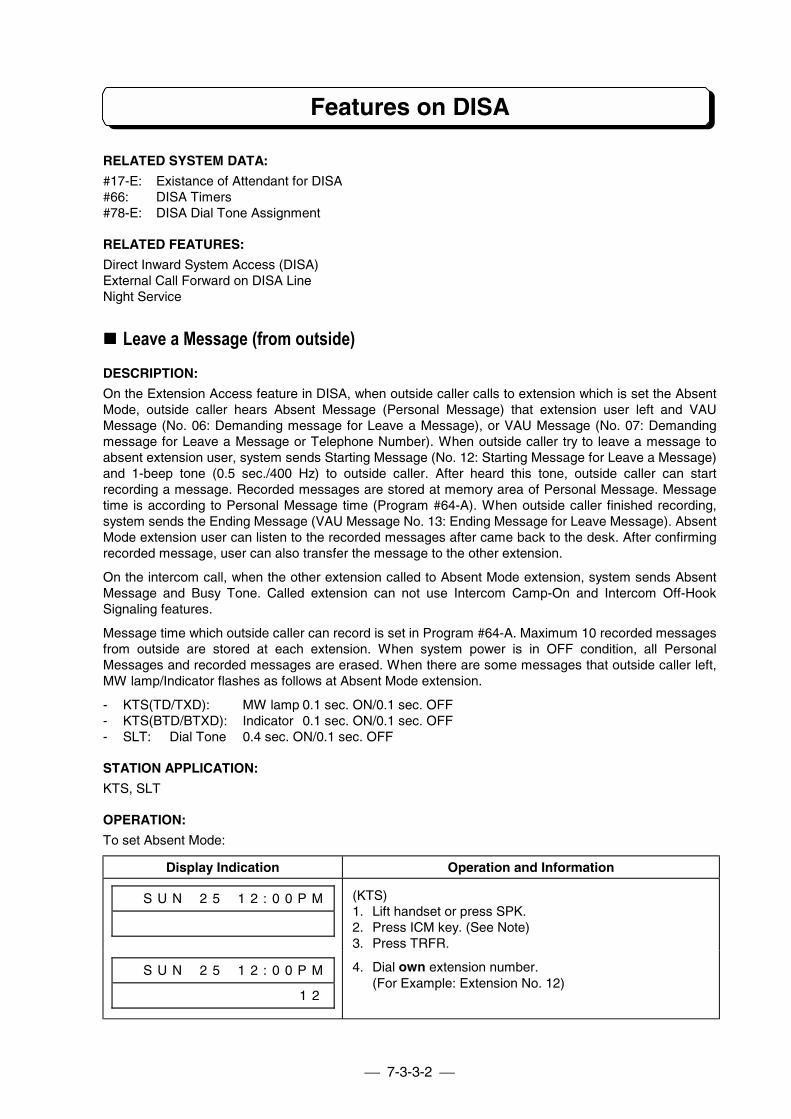
7-3-3-2
Features on DISA
RELATED SYSTEM DATA:
#17-E: Existance of Attendant for DISA#66: DISA Timers#78-E: DISA Dial Tone Assignment
RELATED FEATURES:
Direct Inward System Access (DISA)External Call Forward on DISA LineNight Service
!!!! Leave a Message (from outside)DESCRIPTION:
On the Extension Access feature in DISA, when outside caller calls to extension which is set the AbsentMode, outside caller hears Absent Message (Personal Message) that extension user left and VAUMessage (No. 06: Demanding message for Leave a Message), or VAU Message (No. 07: Demandingmessage for Leave a Message or Telephone Number). When outside caller try to leave a message toabsent extension user, system sends Starting Message (No. 12: Starting Message for Leave a Message)and 1-beep tone (0.5 sec./400 Hz) to outside caller. After heard this tone, outside caller can startrecording a message. Recorded messages are stored at memory area of Personal Message. Messagetime is according to Personal Message time (Program #64-A). When outside caller finished recording,system sends the Ending Message (VAU Message No. 13: Ending Message for Leave Message). AbsentMode extension user can listen to the recorded messages after came back to the desk. After confirmingrecorded message, user can also transfer the message to the other extension.
On the intercom call, when the other extension called to Absent Mode extension, system sends AbsentMessage and Busy Tone. Called extension can not use Intercom Camp-On and Intercom Off-HookSignaling features.
Message time which outside caller can record is set in Program #64-A. Maximum 10 recorded messagesfrom outside are stored at each extension. When system power is in OFF condition, all PersonalMessages and recorded messages are erased. When there are some messages that outside caller left,MW lamp/Indicator flashes as follows at Absent Mode extension.
- KTS(TD/TXD): MW lamp 0.1 sec. ON/0.1 sec. OFF- KTS(BTD/BTXD): Indicator 0.1 sec. ON/0.1 sec. OFF- SLT: Dial Tone 0.4 sec. ON/0.1 sec. OFF
STATION APPLICATION:
KTS, SLT
OPERATION:
To set Absent Mode:
Display Indication Operation and Information
# # S U N # 2 5 # 1 2 : 0 0 P M (KTS)1. Lift handset or press SPK.2. Press ICM key. (See Note)3. Press TRFR.
# # S U N # 2 5 # 1 2 : 0 0 P M
# # # # # # # # # # # # # # 1 2
4. Dial own extension number.(For Example: Extension No. 12)
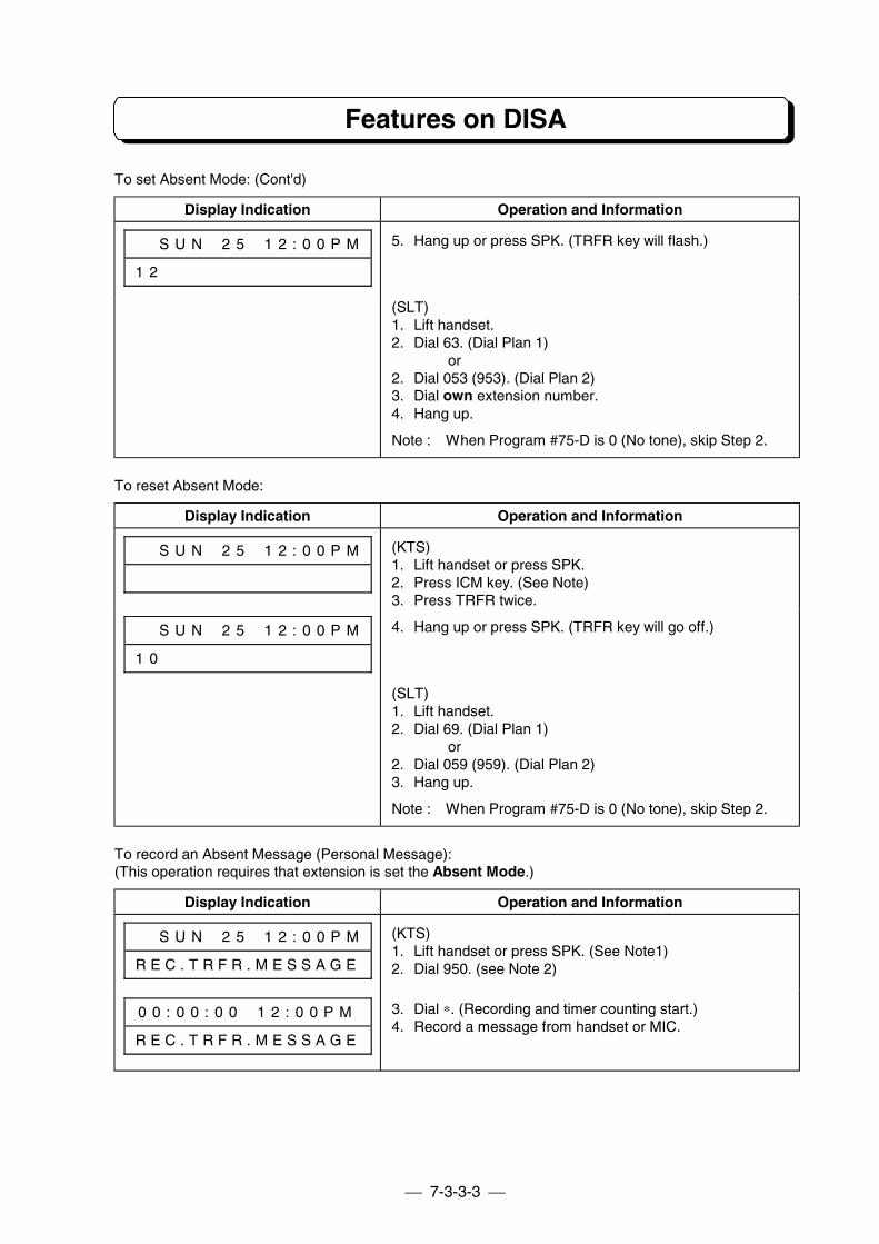
7-3-3-3
Features on DISA
To set Absent Mode: (Cont'd)
Display Indication Operation and Information
# # S U N # 2 5 # 1 2 : 0 0 P M
1 2 # # # # # # # # # # # # # #
5. Hang up or press SPK. (TRFR key will flash.)
(SLT)1. Lift handset.2. Dial 63. (Dial Plan 1)
or2. Dial 053 (953). (Dial Plan 2)3. Dial own extension number.4. Hang up.
Note : When Program #75-D is 0 (No tone), skip Step 2.
To reset Absent Mode:
Display Indication Operation and Information
# # S U N # 2 5 # 1 2 : 0 0 P M (KTS)1. Lift handset or press SPK.2. Press ICM key. (See Note)3. Press TRFR twice.
# # S U N # 2 5 # 1 2 : 0 0 P M
1 0 # # # # # # # # # # # # # #
4. Hang up or press SPK. (TRFR key will go off.)
(SLT)1. Lift handset.2. Dial 69. (Dial Plan 1)
or2. Dial 059 (959). (Dial Plan 2)3. Hang up.
Note : When Program #75-D is 0 (No tone), skip Step 2.
To record an Absent Message (Personal Message):(This operation requires that extension is set the Absent Mode.)
Display Indication Operation and Information
# # S U N # 2 5 # 1 2 : 0 0 P M
R E C . T R F R . M E S S A G E
(KTS)1. Lift handset or press SPK. (See Note1)2. Dial 950. (see Note 2)
0 0 : 0 0 : 0 0 # 1 2 : 0 0 P M
R E C . T R F R . M E S S A G E
3. Dial ∗. (Recording and timer counting start.)4. Record a message from handset or MIC.
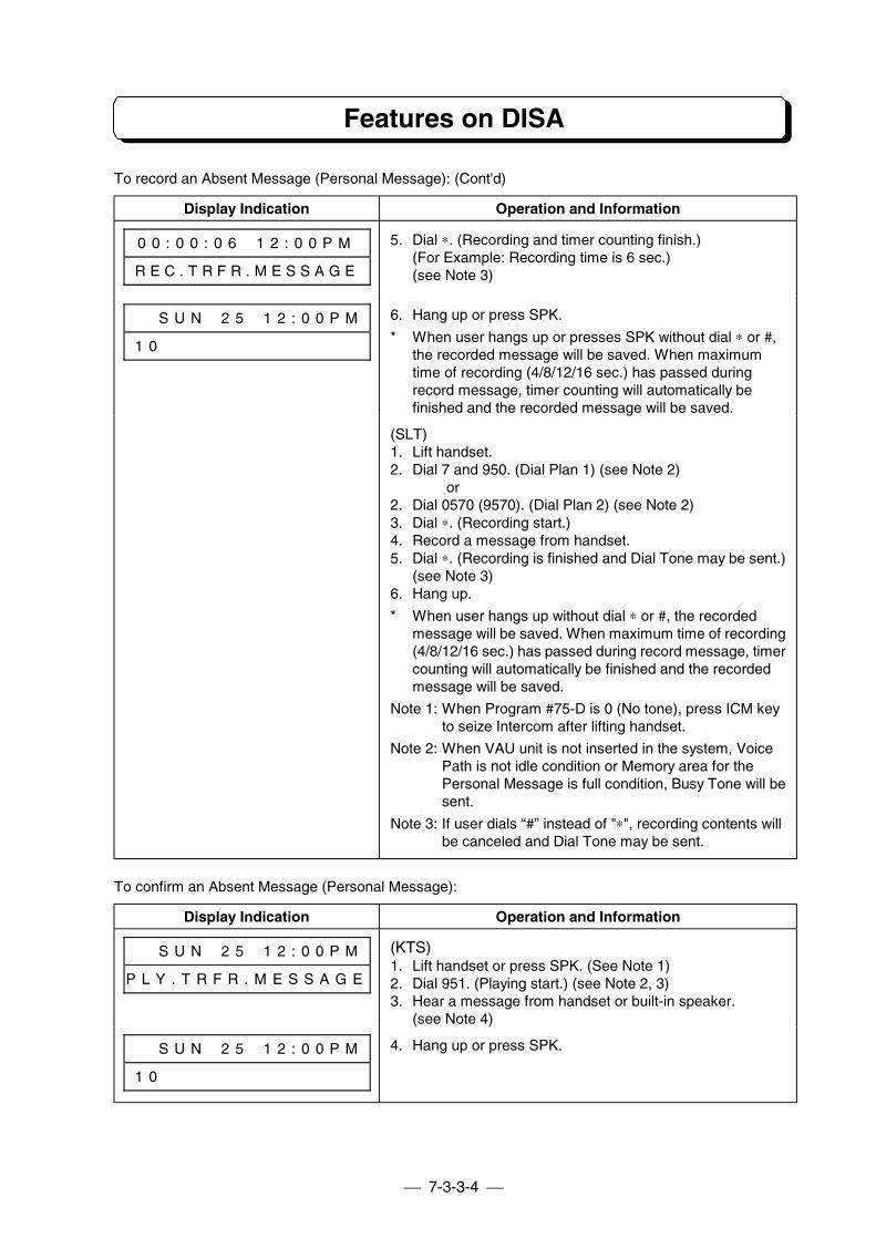
7-3-3-4
Features on DISA
To record an Absent Message (Personal Message): (Cont'd)
Display Indication Operation and Information
0 0 : 0 0 : 0 6 # 1 2 : 0 0 P M
R E C . T R F R . M E S S A G E
5. Dial ∗. (Recording and timer counting finish.)(For Example: Recording time is 6 sec.)(see Note 3)
# # S U N # 2 5 # 1 2 : 0 0 P M
1 0 # # # # # # # # # # # # # #
6. Hang up or press SPK.
* When user hangs up or presses SPK without dial ∗ or #,the recorded message will be saved. When maximumtime of recording (4/8/12/16 sec.) has passed duringrecord message, timer counting will automatically befinished and the recorded message will be saved.
(SLT)1. Lift handset.2. Dial 7 and 950. (Dial Plan 1) (see Note 2)
or2. Dial 0570 (9570). (Dial Plan 2) (see Note 2)3. Dial ∗. (Recording start.)4. Record a message from handset.5. Dial ∗. (Recording is finished and Dial Tone may be sent.)
(see Note 3)6. Hang up.
* When user hangs up without dial ∗ or #, the recordedmessage will be saved. When maximum time of recording(4/8/12/16 sec.) has passed during record message, timercounting will automatically be finished and the recordedmessage will be saved.
Note 1: When Program #75-D is 0 (No tone), press ICM keyto seize Intercom after lifting handset.
Note 2: When VAU unit is not inserted in the system, VoicePath is not idle condition or Memory area for thePersonal Message is full condition, Busy Tone will besent.
Note 3: If user dials “#” instead of "∗", recording contents willbe canceled and Dial Tone may be sent.
To confirm an Absent Message (Personal Message):
Display Indication Operation and Information
# # S U N # 2 5 # 1 2 : 0 0 P M
P L Y . T R F R . M E S S A G E
(KTS)1. Lift handset or press SPK. (See Note 1)2. Dial 951. (Playing start.) (see Note 2, 3)3. Hear a message from handset or built-in speaker.
(see Note 4)
# # S U N # 2 5 # 1 2 : 0 0 P M
1 0 # # # # # # # # # # # # # #
4. Hang up or press SPK.
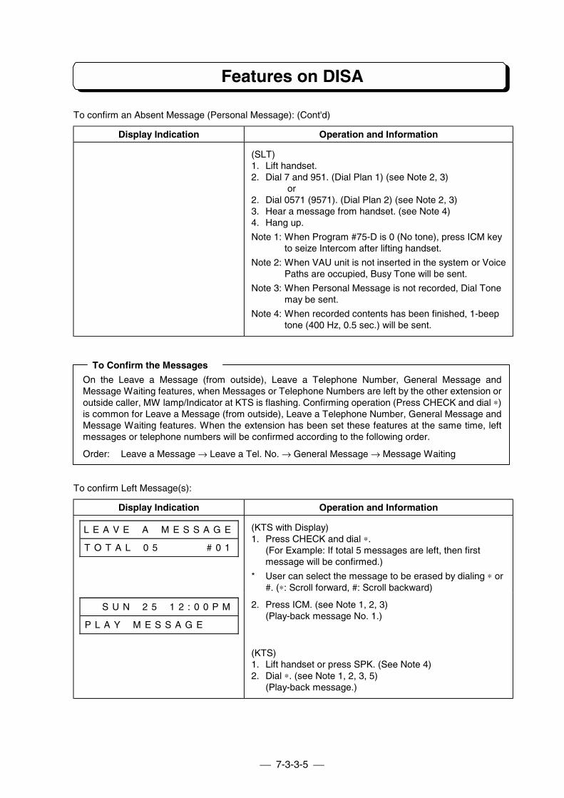
7-3-3-5
Features on DISA
To confirm an Absent Message (Personal Message): (Cont'd)
Display Indication Operation and Information
(SLT)1. Lift handset.2. Dial 7 and 951. (Dial Plan 1) (see Note 2, 3)
or2. Dial 0571 (9571). (Dial Plan 2) (see Note 2, 3)3. Hear a message from handset. (see Note 4)4. Hang up.
Note 1: When Program #75-D is 0 (No tone), press ICM keyto seize Intercom after lifting handset.
Note 2: When VAU unit is not inserted in the system or VoicePaths are occupied, Busy Tone will be sent.
Note 3: When Personal Message is not recorded, Dial Tonemay be sent.
Note 4: When recorded contents has been finished, 1-beeptone (400 Hz, 0.5 sec.) will be sent.
To Confirm the Messages
On the Leave a Message (from outside), Leave a Telephone Number, General Message andMessage Waiting features, when Messages or Telephone Numbers are left by the other extension oroutside caller, MW lamp/Indicator at KTS is flashing. Confirming operation (Press CHECK and dial ∗)is common for Leave a Message (from outside), Leave a Telephone Number, General Message andMessage Waiting features. When the extension has been set these features at the same time, leftmessages or telephone numbers will be confirmed according to the following order.
Order: Leave a Message → Leave a Tel. No. → General Message → Message Waiting
To confirm Left Message(s):
Display Indication Operation and Information
L E A V E # A # M E S S A G E
T O T A L # 0 5 # # # # # # 0 1
(KTS with Display)1. Press CHECK and dial ∗.
(For Example: If total 5 messages are left, then firstmessage will be confirmed.)
* User can select the message to be erased by dialing ∗ or#. (∗: Scroll forward, #: Scroll backward)
# # S U N # 2 5 # 1 2 : 0 0 P M
P L A Y # M E S S A G E # # #
2. Press ICM. (see Note 1, 2, 3)(Play-back message No. 1.)
(KTS)1. Lift handset or press SPK. (See Note 4)2. Dial ∗. (see Note 1, 2, 3, 5)
(Play-back message.)
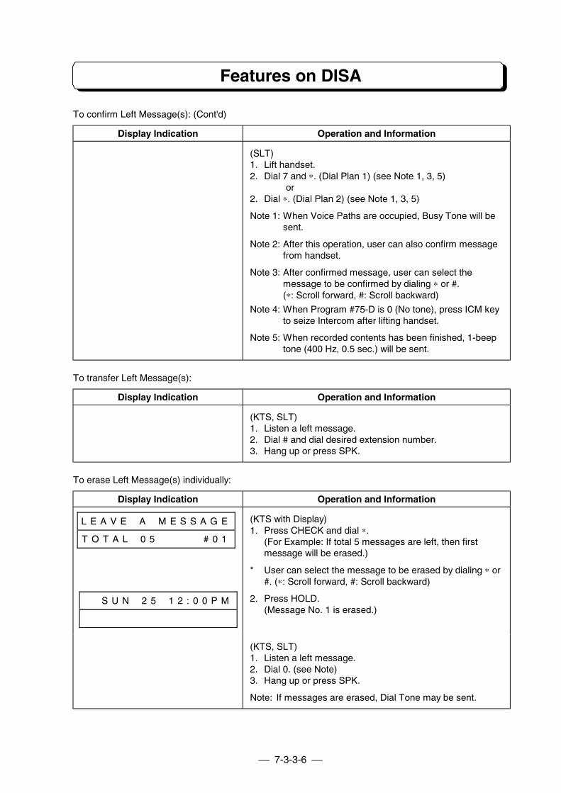
7-3-3-6
Features on DISA
To confirm Left Message(s): (Cont'd)
Display Indication Operation and Information
(SLT)1. Lift handset.2. Dial 7 and ∗. (Dial Plan 1) (see Note 1, 3, 5)
or2. Dial ∗. (Dial Plan 2) (see Note 1, 3, 5)
Note 1: When Voice Paths are occupied, Busy Tone will besent.
Note 2: After this operation, user can also confirm messagefrom handset.
Note 3: After confirmed message, user can select themessage to be confirmed by dialing ∗ or #.(∗: Scroll forward, #: Scroll backward)
Note 4: When Program #75-D is 0 (No tone), press ICM keyto seize Intercom after lifting handset.
Note 5: When recorded contents has been finished, 1-beeptone (400 Hz, 0.5 sec.) will be sent.
To transfer Left Message(s):
Display Indication Operation and Information
(KTS, SLT)1. Listen a left message.2. Dial # and dial desired extension number.3. Hang up or press SPK.
To erase Left Message(s) individually:
Display Indication Operation and Information
L E A V E # A # M E S S A G E
T O T A L # 0 5 # # # # # # 0 1
(KTS with Display)1. Press CHECK and dial ∗.
(For Example: If total 5 messages are left, then firstmessage will be erased.)
* User can select the message to be erased by dialing ∗ or#. (∗: Scroll forward, #: Scroll backward)
# # S U N # 2 5 # 1 2 : 0 0 P M 2. Press HOLD.(Message No. 1 is erased.)
(KTS, SLT)1. Listen a left message.2. Dial 0. (see Note)3. Hang up or press SPK.
Note: If messages are erased, Dial Tone may be sent.
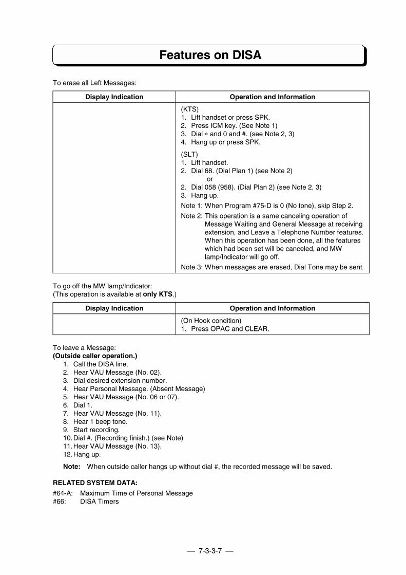
7-3-3-7
Features on DISA
To erase all Left Messages:
Display Indication Operation and Information
(KTS)1. Lift handset or press SPK.2. Press ICM key. (See Note 1)3. Dial ∗ and 0 and #. (see Note 2, 3)4. Hang up or press SPK.
(SLT)1. Lift handset.2. Dial 68. (Dial Plan 1) (see Note 2)
or2. Dial 058 (958). (Dial Plan 2) (see Note 2, 3)3. Hang up.
Note 1: When Program #75-D is 0 (No tone), skip Step 2.
Note 2: This operation is a same canceling operation ofMessage Waiting and General Message at receivingextension, and Leave a Telephone Number features.When this operation has been done, all the featureswhich had been set will be canceled, and MWlamp/Indicator will go off.
Note 3: When messages are erased, Dial Tone may be sent.
To go off the MW lamp/Indicator:(This operation is available at only KTS.)
Display Indication Operation and Information
(On Hook condition)1. Press OPAC and CLEAR.
To leave a Message:(Outside caller operation.)
1. Call the DISA line.2. Hear VAU Message (No. 02).3. Dial desired extension number.4. Hear Personal Message. (Absent Message)5. Hear VAU Message (No. 06 or 07).6. Dial 1.7. Hear VAU Message (No. 11).8. Hear 1 beep tone.9. Start recording.10.Dial #. (Recording finish.) (see Note)11.Hear VAU Message (No. 13).12.Hang up.
Note: When outside caller hangs up without dial #, the recorded message will be saved.
RELATED SYSTEM DATA:
#64-A: Maximum Time of Personal Message#66: DISA Timers
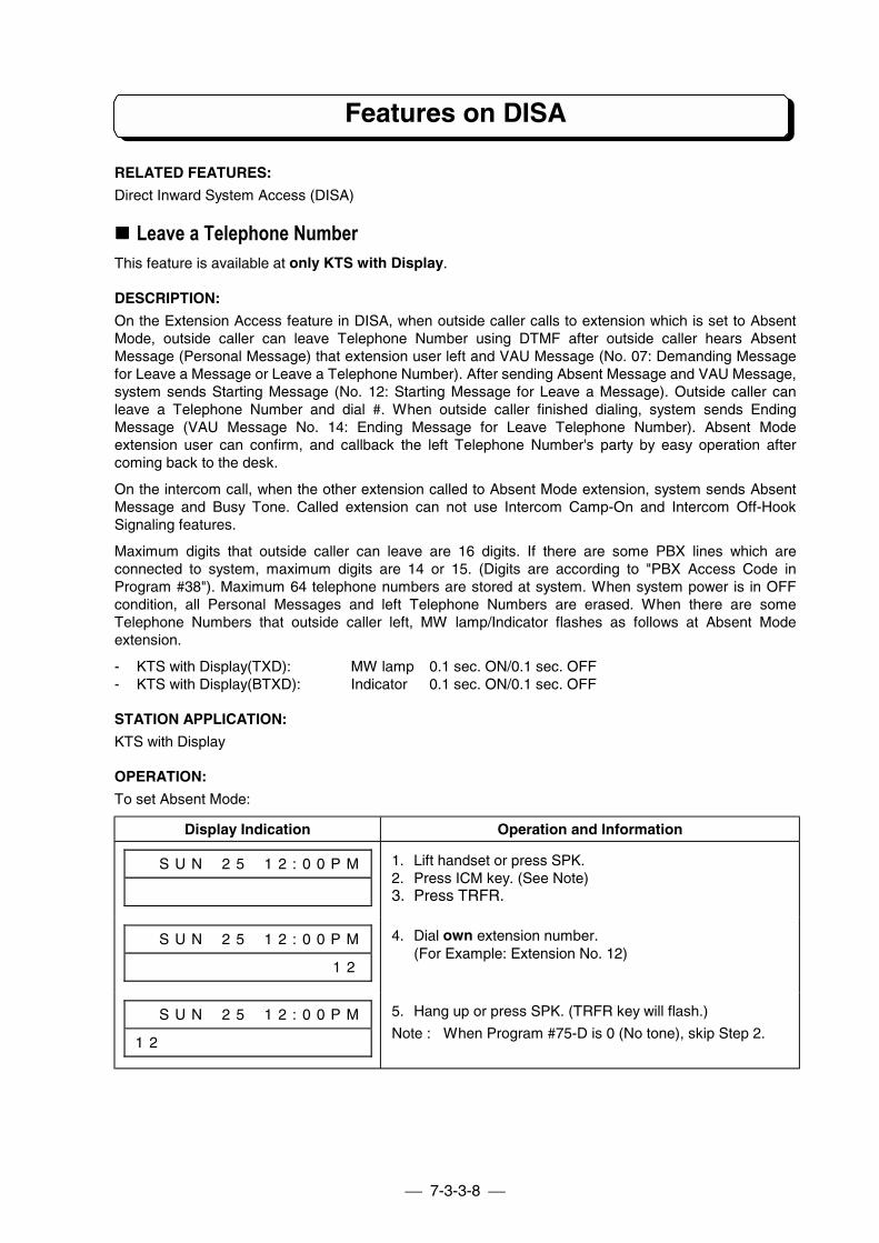
7-3-3-8
Features on DISA
RELATED FEATURES:
Direct Inward System Access (DISA)
!!!! Leave a Telephone NumberThis feature is available at only KTS with Display.
DESCRIPTION:
On the Extension Access feature in DISA, when outside caller calls to extension which is set to AbsentMode, outside caller can leave Telephone Number using DTMF after outside caller hears AbsentMessage (Personal Message) that extension user left and VAU Message (No. 07: Demanding Messagefor Leave a Message or Leave a Telephone Number). After sending Absent Message and VAU Message,system sends Starting Message (No. 12: Starting Message for Leave a Message). Outside caller canleave a Telephone Number and dial #. When outside caller finished dialing, system sends EndingMessage (VAU Message No. 14: Ending Message for Leave Telephone Number). Absent Modeextension user can confirm, and callback the left Telephone Number's party by easy operation aftercoming back to the desk.
On the intercom call, when the other extension called to Absent Mode extension, system sends AbsentMessage and Busy Tone. Called extension can not use Intercom Camp-On and Intercom Off-HookSignaling features.
Maximum digits that outside caller can leave are 16 digits. If there are some PBX lines which areconnected to system, maximum digits are 14 or 15. (Digits are according to "PBX Access Code inProgram #38"). Maximum 64 telephone numbers are stored at system. When system power is in OFFcondition, all Personal Messages and left Telephone Numbers are erased. When there are someTelephone Numbers that outside caller left, MW lamp/Indicator flashes as follows at Absent Modeextension.
- KTS with Display(TXD): MW lamp 0.1 sec. ON/0.1 sec. OFF- KTS with Display(BTXD): Indicator 0.1 sec. ON/0.1 sec. OFF
STATION APPLICATION:
KTS with Display
OPERATION:
To set Absent Mode:
Display Indication Operation and Information
# # S U N # 2 5 # 1 2 : 0 0 P M 1. Lift handset or press SPK.2. Press ICM key. (See Note)3. Press TRFR.
# # S U N # 2 5 # 1 2 : 0 0 P M
# # # # # # # # # # # # # # 1 2
4. Dial own extension number.(For Example: Extension No. 12)
# # S U N # 2 5 # 1 2 : 0 0 P M
1 2 # # # # # # # # # # # # # #
5. Hang up or press SPK. (TRFR key will flash.)
Note : When Program #75-D is 0 (No tone), skip Step 2.
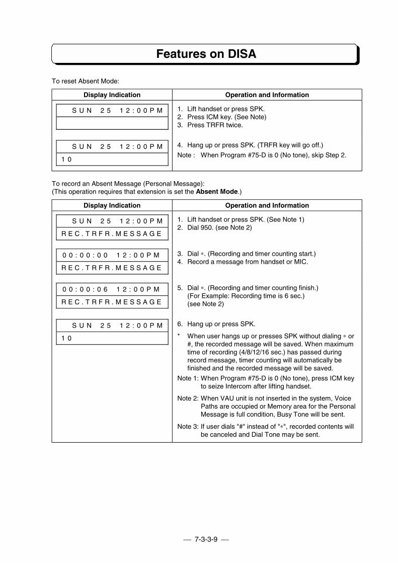
7-3-3-9
Features on DISA
To reset Absent Mode:
Display Indication Operation and Information
# # S U N # 2 5 # 1 2 : 0 0 P M 1. Lift handset or press SPK.2. Press ICM key. (See Note)3. Press TRFR twice.
# # S U N # 2 5 # 1 2 : 0 0 P M
1 0 # # # # # # # # # # # # # #
4. Hang up or press SPK. (TRFR key will go off.)
Note : When Program #75-D is 0 (No tone), skip Step 2.
To record an Absent Message (Personal Message):(This operation requires that extension is set the Absent Mode.)
Display Indication Operation and Information
# # S U N # 2 5 # 1 2 : 0 0 P M
R E C . T R F R . M E S S A G E
1. Lift handset or press SPK. (See Note 1)2. Dial 950. (see Note 2)
0 0 : 0 0 : 0 0 # 1 2 : 0 0 P M
R E C . T R F R . M E S S A G E
3. Dial ∗. (Recording and timer counting start.)4. Record a message from handset or MIC.
0 0 : 0 0 : 0 6 # 1 2 : 0 0 P M
R E C . T R F R . M E S S A G E
5. Dial ∗. (Recording and timer counting finish.)(For Example: Recording time is 6 sec.)(see Note 2)
# # S U N # 2 5 # 1 2 : 0 0 P M
1 0 # # # # # # # # # # # # # #
6. Hang up or press SPK.
* When user hangs up or presses SPK without dialing ∗ or#, the recorded message will be saved. When maximumtime of recording (4/8/12/16 sec.) has passed duringrecord message, timer counting will automatically befinished and the recorded message will be saved.
Note 1: When Program #75-D is 0 (No tone), press ICM keyto seize Intercom after lifting handset.
Note 2: When VAU unit is not inserted in the system, VoicePaths are occupied or Memory area for the PersonalMessage is full condition, Busy Tone will be sent.
Note 3: If user dials "#" instead of "∗", recorded contents willbe canceled and Dial Tone may be sent.
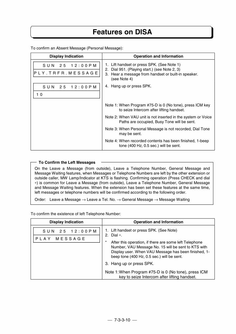
7-3-3-10
Features on DISA
To confirm an Absent Message (Personal Message):
Display Indication Operation and Information
# # S U N # 2 5 # 1 2 : 0 0 P M
P L Y . T R F R . M E S S A G E
1. Lift handset or press SPK. (See Note 1)2. Dial 951. (Playing start.) (see Note 2, 3)3. Hear a message from handset or built-in speaker.
(see Note 4)
# # S U N # 2 5 # 1 2 : 0 0 P M
1 0 # # # # # # # # # # # # # #
4. Hang up or press SPK.
Note 1: When Program #75-D is 0 (No tone), press ICM keyto seize Intercom after lifting handset.
Note 2: When VAU unit is not inserted in the system or VoicePaths are occupied, Busy Tone will be sent.
Note 3: When Personal Message is not recorded, Dial Tonemay be sent.
Note 4: When recorded contents has been finished, 1-beeptone (400 Hz, 0.5 sec.) will be sent.
To Confirm the Left Messages
On the Leave a Message (from outside), Leave a Telephone Number, General Message andMessage Waiting features, when Messages or Telephone Numbers are left by the other extension oroutside caller, MW Lamp/Indicator at KTS is flashing. Confirming operation (Press CHECK and dial∗) is common for Leave a Message (from outside), Leave a Telephone Number, General Messageand Message Waiting features. When the extension has been set these features at the same time,left messages or telephone numbers will be confirmed according to the following order.
Order: Leave a Message → Leave a Tel. No. → General Message → Message Waiting
To confirm the existence of left Telephone Number:
Display Indication Operation and Information
# # S U N # 2 5 # 1 2 : 0 0 P M
P L A Y # M E S S A G E # # #
1. Lift handset or press SPK. (See Note)2. Dial ∗.
* After this operation, if there are some left TelephoneNumber, VAU Message No. 15 will be sent to KTS withDisplay user. When VAU Message has been finished, 1-beep tone (400 Hz, 0.5 sec.) will be sent.
3. Hang up or press SPK.
Note 1:When Program #75-D is 0 (No tone), press ICMkey to seize Intercom after lifting handset.
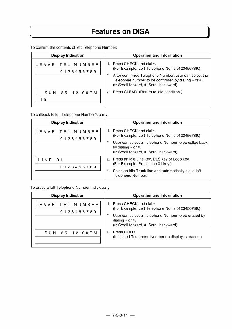
7-3-3-11
Features on DISA
To confirm the contents of left Telephone Number:
Display Indication Operation and Information
L E A V E # T E L . N U M B E R
# # # # # # 0 1 2 3 4 5 6 7 8 9
1. Press CHECK and dial ∗.(For Example: Left Telephone No. is 0123456789.)
* After confirmed Telephone Number, user can select theTelephone number to be confirmed by dialing ∗ or #.(∗: Scroll forward, #: Scroll backward)
# # S U N # 2 5 # 1 2 : 0 0 P M
1 0 # # # # # # # # # # # # #
2. Press CLEAR. (Return to idle condition.)
To callback to left Telephone Number's party:
Display Indication Operation and Information
L E A V E # T E L . N U M B E R
# # # # # # 0 1 2 3 4 5 6 7 8 9
1. Press CHECK and dial ∗.(For Example: Left Telephone No. is 0123456789.)
* User can select a Telephone Number to be called backby dialing ∗ or #.(∗: Scroll forward, #: Scroll backward)
L I N E # 0 1 # # # # # # # # #
# # # # # # 0 1 2 3 4 5 6 7 8 9
2. Press an idle Line key, DLS key or Loop key.(For Example: Press Line 01 key.)
* Seize an idle Trunk line and automatically dial a leftTelephone Number.
To erase a left Telephone Number individually:
Display Indication Operation and Information
L E A V E # T E L . N U M B E R
# # # # # # 0 1 2 3 4 5 6 7 8 9
1. Press CHECK and dial ∗.(For Example: Left Telephone No. is 0123456789.)
* User can select a Telephone Number to be erased bydialing ∗ or #.(∗: Scroll forward, #: Scroll backward)
# # S U N # 2 5 # 1 2 : 0 0 P M 2. Press HOLD.(Indicated Telephone Number on display is erased.)
7-3-3-12
Features on DISA
To erase all left Telephone Numbers: (To go off the MW Lamp/Indicator:)
Display Indication Operation and Information
(On Hook condition)1. Press OPAC and CLEAR.
Or
1. Lift handset or press SPK.2. Press ICM key. (See Note 1)3. Dial ∗ and 0 and #.4. Hang up or press SPK.
Note 1: When Program #75-D is 0 (No tone), skip Step 2.
To leave a Telephone Number:(Outside caller’s operation.)
1. Call the DISA line.2. Hear VAU Message (No. 02).3. Dial desired extension number.4. Hear Personal Message. (Absent Message)5. Hear VAU Message (No. 07)6. Dial 2.7. Hear VAU Message (No. 12). (Dial Tone may be heard)8. Dial Telephone Number using DTMF. (This Number shall be stored.)9. Dial #. (Recording finish.) (see Note)10.Hear VAU Message (No. 14)11.Hang up.
Note: When outside caller hangs up without dialing #, the recorded number will be saved.
RELATED SYSTEM DATA:
#64-A: Maximum Time of Personal Message#66: DISA Timers
RELATED FEATURES:
Direct Inward System Access (DISA)
!!!! External Call Forward to Mobile PhoneDESCRIPTION:
When outside caller calls to an extension (key telephone) in Absent Mode, through DISA line and dials “3”,External Call Forward Message (VAU Message No.1: External Call Forward Message) is sent to theoutside caller, and this call is automatically transferred to the mobile phone whose No. is stored underOne-Touch key No.9.
STATION APPLICATION:
KTS
7-3-3-13
Features on DISA
OPERATION:
To set External Call Forward to Mobile Phone:
1. Store the desired mobile phone No. to One-Touch key No.9. (Max. 18 digits including TrunkAccess Code.)
2. Set Absent Mode.
(Outside caller operation)
1. Call DISA line.2. Hear VAU Message (No. 02).3. Dial desired extension number.4. Hear Personal Message or VAU Message No.07. (Absent Message)5. Dial 3.6. Hear VAU Message No. 01.
- An idle Trunk line is seized and the stored mobile phone No. is dialed.7. Make conversation with the mobile phone user.
Note: This conversation is same as Trunk-to-Trunk feature. Dial “#”, “#” to finish theconversation.
!!!! Call Information to PagerDESCRIPTION:
If outside caller left a message to key telephone through DISA line, key telephone automatically dialspager number which is stored at One-Touch key No.7 and No.8.
STATION APPLICATION:
KTS
OPERATION:
To set Call Information to Pager:
1. Store the desired pager No. to One-Touch key No.7 (Max. 18 digits including Trunk AccessCode) ,and if the pager No. exceeds 18 digits, store the rest to No.8 (Max. 18 digits).
Note: The numbers stored at One-Touch key No.7 and No.8 are continuously dialed.2. . Set Absent Mode
(Outside caller operation)
1. Call DISA line.2. Hear VAU Message (No. 02).3. Dial desired extension number.4. Hear Personal Message or VAU Message No.07. (Absent Message)5. Dial 1 and leave a message.
- An idle Trunk line is automatically seized and the stored pager No. is dialed after the message isleft by the outside caller.
6. Hang up.
7-3-3-14
Features on DISA
RELATED SYSTEM DATA:
#75-A: Auto-dial Assignment
RELATED FEATURES:
Direct Inward System Access (DISA)One-Touch Dialing
!!!! Message Playback from OutsideDESCRIPTION:
The extension user who sets Absent Mode can playback the left messages from outside through DISAline. A 4-digit password to listen to the messages can be assigned per extension in Program #76.
STATION APPLICATION:
KTS, SLT
OPERATION:
The extension must be set to Absent Mode.
(Outside caller operation)
1. Call DISA line.2. Hear VAU Message (No. 02).3. Dial desired extension number.4. Hear Personal Message or VAU Message No.07. (Absent Message)5. Dial 0 and 4 digits password.
Note: If the password is not correct Error message (VAU Message No.09) is sent.- Beep tone is sent as a confirmation tone after a left message is sent to the outside caller.
6. Dial “0” to clear the message, “∗” to play the next message, or “#” to finish.Note: If nothing is dialed within the “Dial waiting time (Program#66-2)”, Cut-Off
Message (VAU Message No.05) is sent and this line will be terminated.
RELATED SYSTEM DATA:
#76: Password for Message Playback
RELATED FEATURES:
Direct Inward System Access (DISA)
!!!! Waiting MessageDESCRIPTION:
When an outside caller calls to DISA line, Waiting Message (VAU Message No.25: Waiting Message) issent to the outside caller repeatedly instead of music on hold while the system is calling the desiredextension. Sending interval time for the message can be set by Program #66-4.
STATION APPLICATION:
System
7-3-3-15
Features on DISA
OPERATION:To record Waiting Message:
- Refer to How to Record VAU message.
Note: Waiting Message (VAU Message No.25: Waiting Message) must be recorded before usingthis feature.
RELATED SYSTEM DATA:
#66-4: VAU Message No.25 Waiting Time
RELATED FEATURES:
Direct Inward System Access (DISA)
Features on Transfer
!!!! Call Forward with Guidance MessageDESCRIPTION:
On the Call Forward feature, system can send a Transfer Message (Personal Massage) before this call istransferred to the other extension.On the Extension Access on DISA feature, when outside caller called to Call Forward Mode extension,outside caller hears Transfer Message (Personal Message) and this call is automatically transferred to theother extension. Destination extension is set by Call Forward Mode extension. After this call wastransferred, destination extension rings. If destination extension did not answer within time which is set inProgram #66-3, this call will be transferred to Operator. When extension user forgot to record the TransferMessage, system sends the substitution of Transfer Message (VAU Message No. 03: Transfer Message)for Personal Message to outside caller.
On the intercom call, the same functions as above are applicable basically. But if extension user forgotrecording the Transfer message, system automatically transfers to destination extension without sendingthe message. When intercom call is transferred to destination extension, destination extension rings.
When system power is in OFF condition, all Personal Messages are erased.
STATION APPLICATION:
KTS, SLT
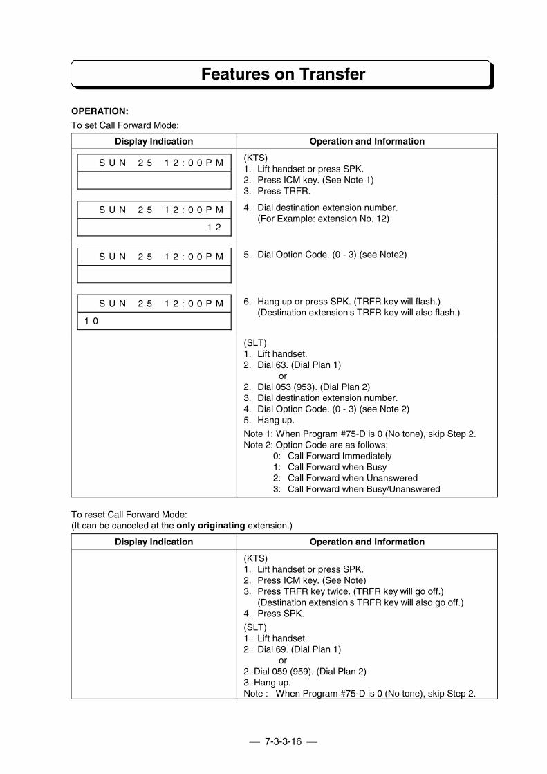
7-3-3-16
Features on Transfer
OPERATION:
To set Call Forward Mode:
Display Indication Operation and Information
# # S U N # 2 5 # 1 2 : 0 0 P M (KTS)1. Lift handset or press SPK.2. Press ICM key. (See Note 1)3. Press TRFR.
# # S U N # 2 5 # 1 2 : 0 0 P M
# # # # # # # # # # # # # # 1 2
4. Dial destination extension number.(For Example: extension No. 12)
# # S U N # 2 5 # 1 2 : 0 0 P M 5. Dial Option Code. (0 - 3) (see Note2)
# # S U N # 2 5 # 1 2 : 0 0 P M
1 0 # # # # # # # # # # # # # #
6. Hang up or press SPK. (TRFR key will flash.)(Destination extension's TRFR key will also flash.)
(SLT)1. Lift handset.2. Dial 63. (Dial Plan 1)
or2. Dial 053 (953). (Dial Plan 2)3. Dial destination extension number.4. Dial Option Code. (0 - 3) (see Note 2)5. Hang up.
Note 1: When Program #75-D is 0 (No tone), skip Step 2.Note 2: Option Code are as follows;
0: Call Forward Immediately1: Call Forward when Busy2: Call Forward when Unanswered3: Call Forward when Busy/Unanswered
To reset Call Forward Mode:(It can be canceled at the only originating extension.)
Display Indication Operation and Information
(KTS)1. Lift handset or press SPK.2. Press ICM key. (See Note)3. Press TRFR key twice. (TRFR key will go off.)
(Destination extension's TRFR key will also go off.)4. Press SPK.
(SLT)1. Lift handset.2. Dial 69. (Dial Plan 1)
or2. Dial 059 (959). (Dial Plan 2)3. Hang up.Note : When Program #75-D is 0 (No tone), skip Step 2.
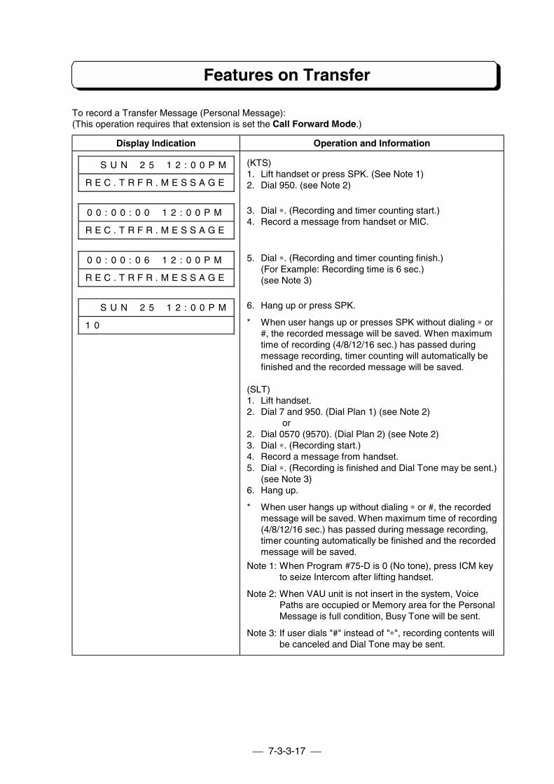
7-3-3-17
Features on Transfer
To record a Transfer Message (Personal Message):(This operation requires that extension is set the Call Forward Mode.)
Display Indication Operation and Information
# # S U N # 2 5 # 1 2 : 0 0 P M
R E C . T R F R . M E S S A G E
(KTS)1. Lift handset or press SPK. (See Note 1)2. Dial 950. (see Note 2)
0 0 : 0 0 : 0 0 # 1 2 : 0 0 P M
R E C . T R F R . M E S S A G E
3. Dial ∗. (Recording and timer counting start.)4. Record a message from handset or MIC.
0 0 : 0 0 : 0 6 # 1 2 : 0 0 P M
R E C . T R F R . M E S S A G E
5. Dial ∗. (Recording and timer counting finish.)(For Example: Recording time is 6 sec.)(see Note 3)
# # S U N # 2 5 # 1 2 : 0 0 P M
1 0 # # # # # # # # # # # # # #
6. Hang up or press SPK.
* When user hangs up or presses SPK without dialing ∗ or#, the recorded message will be saved. When maximumtime of recording (4/8/12/16 sec.) has passed duringmessage recording, timer counting will automatically befinished and the recorded message will be saved.
(SLT)1. Lift handset.2. Dial 7 and 950. (Dial Plan 1) (see Note 2)
or2. Dial 0570 (9570). (Dial Plan 2) (see Note 2)3. Dial ∗. (Recording start.)4. Record a message from handset.5. Dial ∗. (Recording is finished and Dial Tone may be sent.)
(see Note 3)6. Hang up.
* When user hangs up without dialing ∗ or #, the recordedmessage will be saved. When maximum time of recording(4/8/12/16 sec.) has passed during message recording,timer counting automatically be finished and the recordedmessage will be saved.
Note 1: When Program #75-D is 0 (No tone), press ICM keyto seize Intercom after lifting handset.
Note 2: When VAU unit is not insert in the system, VoicePaths are occupied or Memory area for the PersonalMessage is full condition, Busy Tone will be sent.
Note 3: If user dials "#" instead of "∗", recording contents willbe canceled and Dial Tone may be sent.
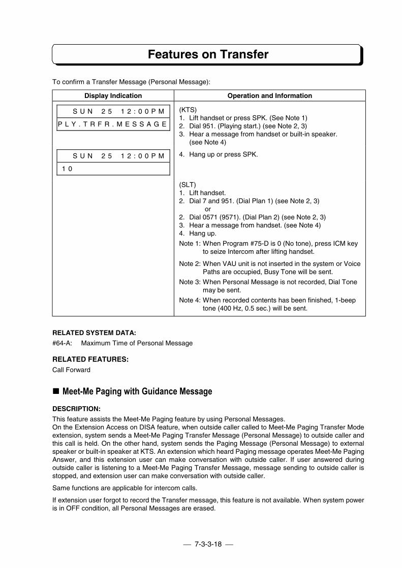
7-3-3-18
Features on Transfer
To confirm a Transfer Message (Personal Message):
Display Indication Operation and Information
# # S U N # 2 5 # 1 2 : 0 0 P M
P L Y . T R F R . M E S S A G E
(KTS)1. Lift handset or press SPK. (See Note 1)2. Dial 951. (Playing start.) (see Note 2, 3)3. Hear a message from handset or built-in speaker.
(see Note 4)
# # S U N # 2 5 # 1 2 : 0 0 P M
1 0 # # # # # # # # # # # # # #
4. Hang up or press SPK.
(SLT)1. Lift handset.2. Dial 7 and 951. (Dial Plan 1) (see Note 2, 3)
or2. Dial 0571 (9571). (Dial Plan 2) (see Note 2, 3)3. Hear a message from handset. (see Note 4)4. Hang up.
Note 1: When Program #75-D is 0 (No tone), press ICM keyto seize Intercom after lifting handset.
Note 2: When VAU unit is not inserted in the system or VoicePaths are occupied, Busy Tone will be sent.
Note 3: When Personal Message is not recorded, Dial Tonemay be sent.
Note 4: When recorded contents has been finished, 1-beeptone (400 Hz, 0.5 sec.) will be sent.
RELATED SYSTEM DATA:
#64-A: Maximum Time of Personal Message
RELATED FEATURES:Call Forward
!!!! Meet-Me Paging with Guidance MessageDESCRIPTION:
This feature assists the Meet-Me Paging feature by using Personal Messages.On the Extension Access on DISA feature, when outside caller called to Meet-Me Paging Transfer Modeextension, system sends a Meet-Me Paging Transfer Message (Personal Message) to outside caller andthis call is held. On the other hand, system sends the Paging Message (Personal Message) to externalspeaker or built-in speaker at KTS. An extension which heard Paging message operates Meet-Me PagingAnswer, and this extension user can make conversation with outside caller. If user answered duringoutside caller is listening to a Meet-Me Paging Transfer Message, message sending to outside caller isstopped, and extension user can make conversation with outside caller.
Same functions are applicable for intercom calls.
If extension user forgot to record the Transfer message, this feature is not available. When system poweris in OFF condition, all Personal Messages are erased.
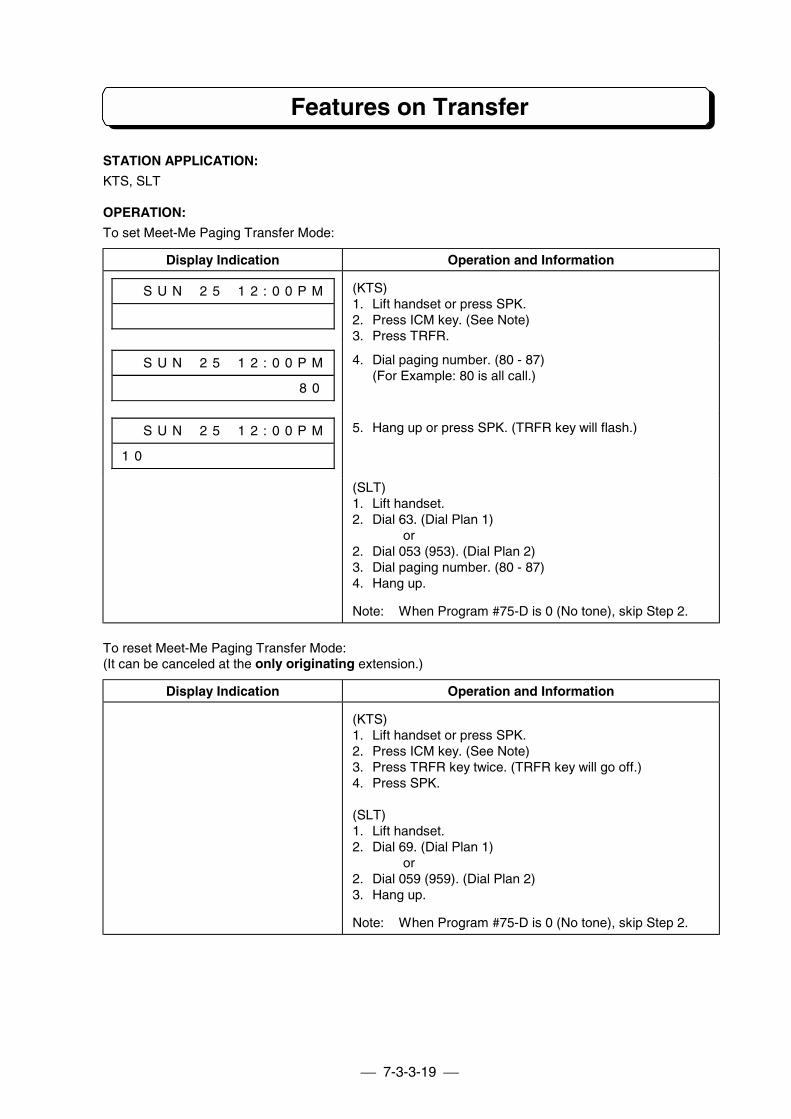
7-3-3-19
Features on Transfer
STATION APPLICATION:
KTS, SLT
OPERATION:
To set Meet-Me Paging Transfer Mode:
Display Indication Operation and Information
# # S U N # 2 5 # 1 2 : 0 0 P M (KTS)1. Lift handset or press SPK.2. Press ICM key. (See Note)3. Press TRFR.
# # S U N # 2 5 # 1 2 : 0 0 P M
# # # # # # # # # # # # # # 8 0
4. Dial paging number. (80 - 87)(For Example: 80 is all call.)
# # S U N # 2 5 # 1 2 : 0 0 P M
1 0 # # # # # # # # # # # # # #
5. Hang up or press SPK. (TRFR key will flash.)
(SLT)1. Lift handset.2. Dial 63. (Dial Plan 1)
or2. Dial 053 (953). (Dial Plan 2)3. Dial paging number. (80 - 87)4. Hang up.
Note: When Program #75-D is 0 (No tone), skip Step 2.
To reset Meet-Me Paging Transfer Mode:(It can be canceled at the only originating extension.)
Display Indication Operation and Information
(KTS)1. Lift handset or press SPK.2. Press ICM key. (See Note)3. Press TRFR key twice. (TRFR key will go off.)4. Press SPK.
(SLT)1. Lift handset.2. Dial 69. (Dial Plan 1)
or2. Dial 059 (959). (Dial Plan 2)3. Hang up.
Note: When Program #75-D is 0 (No tone), skip Step 2.
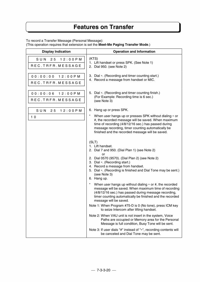
7-3-3-20
Features on Transfer
To record a Transfer Message (Personal Message):(This operation requires that extension is set the Meet-Me Paging Transfer Mode.)
Display Indication Operation and Information
# # S U N # 2 5 # 1 2 : 0 0 P M
R E C . T R F R . M E S S A G E
(KTS)1. Lift handset or press SPK. (See Note 1)2. Dial 950. (see Note 2)
0 0 : 0 0 : 0 0 # 1 2 : 0 0 P M
R E C . T R F R . M E S S A G E
3. Dial ∗. (Recording and timer counting start.)4. Record a message from handset or MIC.
0 0 : 0 0 : 0 6 # 1 2 : 0 0 P M
R E C . T R F R . M E S S A G E
5. Dial ∗. (Recording and timer counting finish.)(For Example: Recording time is 6 sec.)(see Note 3)
# # S U N # 2 5 # 1 2 : 0 0 P M
1 0 # # # # # # # # # # # # # #
6. Hang up or press SPK.
* When user hangs up or presses SPK without dialing ∗ or#, the recorded message will be saved. When maximumtime of recording (4/8/12/16 sec.) has passed duringmessage recording, timer counting automatically befinished and the recorded message will be saved.
(SLT)1. Lift handset.2. Dial 7 and 950. (Dial Plan 1) (see Note 2)
or2. Dial 0570 (9570). (Dial Plan 2) (see Note 2)3. Dial ∗. (Recording start.)4. Record a message from handset.5. Dial ∗. (Recording is finished and Dial Tone may be sent.)
(see Note 3)6. Hang up.
* When user hangs up without dialing ∗ or #, the recordedmessage will be saved. When maximum time of recording(4/8/12/16 sec.) has passed during message recording,timer counting automatically be finished and the recordedmessage will be saved.
Note 1: When Program #75-D is 0 (No tone), press ICM keyto seize Intercom after lifting handset.
Note 2: When VAU unit is not insert in the system, VoicePaths are occupied or Memory area for the PersonalMessage is full condition, Busy Tone will be sent.
Note 3: If user dials "#" instead of "∗", recording contents willbe canceled and Dial Tone may be sent.
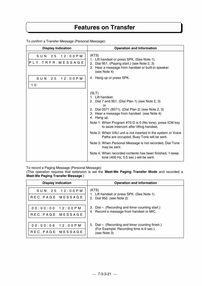
7-3-3-21
Features on Transfer
To confirm a Transfer Message (Personal Message):
Display Indication Operation and Information
# # S U N # 2 5 # 1 2 : 0 0 P M
P L Y . T R F R . M E S S A G E
(KTS)1. Lift handset or press SPK. (See Note 1)2. Dial 951. (Playing start.) (see Note 2, 3)3. Hear a message from handset or built-in speaker.
(see Note 4)
# # S U N # 2 5 # 1 2 : 0 0 P M
1 0 # # # # # # # # # # # # # #
4. Hang up or press SPK.
(SLT)1. Lift handset.2. Dial 7 and 951. (Dial Plan 1) (see Note 2, 3)
or2. Dial 0571 (9571). (Dial Plan 2) (see Note 2, 3)3. Hear a message from handset. (see Note 4)4. Hang up.
Note 1: When Program #75-D is 0 (No tone), press ICM keyto seize Intercom after lifting handset.
Note 2: When VAU unit is not inserted in the system or VoicePaths are occupied, Busy Tone will be sent.
Note 3: When Personal Message is not recorded, Dial Tonemay be sent.
Note 4: When recorded contents has been finished, 1-beeptone (400 Hz, 0.5 sec.) will be sent.
To record a Paging Message (Personal Message):(This operation requires that extension is set the Meet-Me Paging Transfer Mode and recorded aMeet-Me Paging Transfer Message.)
Display Indication Operation and Information
# # S U N # 2 5 # 1 2 : 0 0 P M
R E C . P A G E # M E S S A G E
(KTS)1. Lift handset or press SPK. (See Note 1)2. Dial 952. (see Note 2)
0 0 : 0 0 : 0 0 # 1 2 : 0 0 P M
R E C . P A G E # M E S S A G E
3. Dial ∗. (Recording and timer counting start.)4. Record a message from handset or MIC.
0 0 : 0 0 : 0 6 # 1 2 : 0 0 P M
R E C . P A G E # M E S S A G E
5. Dial ∗. (Recording and timer counting finish.)(For Example: Recording time is 6 sec.)(see Note 3)
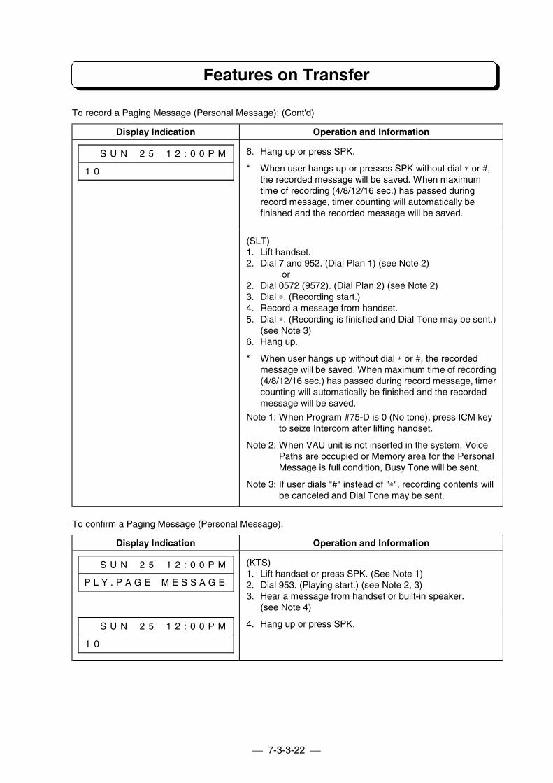
7-3-3-22
Features on Transfer
To record a Paging Message (Personal Message): (Cont'd)
Display Indication Operation and Information
# # S U N # 2 5 # 1 2 : 0 0 P M
1 0 # # # # # # # # # # # # # #
6. Hang up or press SPK.
* When user hangs up or presses SPK without dial ∗ or #,the recorded message will be saved. When maximumtime of recording (4/8/12/16 sec.) has passed duringrecord message, timer counting will automatically befinished and the recorded message will be saved.
(SLT)1. Lift handset.2. Dial 7 and 952. (Dial Plan 1) (see Note 2)
or2. Dial 0572 (9572). (Dial Plan 2) (see Note 2)3. Dial ∗. (Recording start.)4. Record a message from handset.5. Dial ∗. (Recording is finished and Dial Tone may be sent.)
(see Note 3)6. Hang up.
* When user hangs up without dial ∗ or #, the recordedmessage will be saved. When maximum time of recording(4/8/12/16 sec.) has passed during record message, timercounting will automatically be finished and the recordedmessage will be saved.
Note 1: When Program #75-D is 0 (No tone), press ICM keyto seize Intercom after lifting handset.
Note 2: When VAU unit is not inserted in the system, VoicePaths are occupied or Memory area for the PersonalMessage is full condition, Busy Tone will be sent.
Note 3: If user dials "#" instead of "∗", recording contents willbe canceled and Dial Tone may be sent.
To confirm a Paging Message (Personal Message):
Display Indication Operation and Information
# # S U N # 2 5 # 1 2 : 0 0 P M
P L Y . P A G E # M E S S A G E
(KTS)1. Lift handset or press SPK. (See Note 1)2. Dial 953. (Playing start.) (see Note 2, 3)3. Hear a message from handset or built-in speaker.
(see Note 4)
# # S U N # 2 5 # 1 2 : 0 0 P M
1 0 # # # # # # # # # # # # # #
4. Hang up or press SPK.
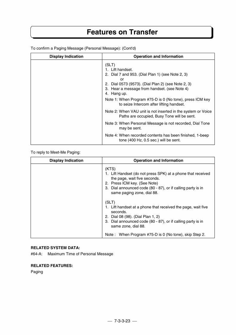
7-3-3-23
Features on Transfer
To confirm a Paging Message (Personal Message): (Cont'd)
Display Indication Operation and Information
(SLT)1. Lift handset.2. Dial 7 and 953. (Dial Plan 1) (see Note 2, 3)
or2. Dial 0573 (9573). (Dial Plan 2) (see Note 2, 3)3. Hear a message from handset. (see Note 4)4. Hang up.
Note 1: When Program #75-D is 0 (No tone), press ICM keyto seize Intercom after lifting handset.
Note 2: When VAU unit is not inserted in the system or VoicePaths are occupied, Busy Tone will be sent.
Note 3: When Personal Message is not recorded, Dial Tonemay be sent.
Note 4: When recorded contents has been finished, 1-beeptone (400 Hz, 0.5 sec.) will be sent.
To reply to Meet-Me Paging:
Display Indication Operation and Information
(KTS)1. Lift Handset (do not press SPK) at a phone that received
the page, wait five seconds.2. Press ICM key. (See Note)3. Dial announced code (80 - 87), or if calling party is in
same paging zone, dial 88.
(SLT)1. Lift handset at a phone that received the page, wait five
seconds.2. Dial 08 (98). (Dial Plan 1, 2)3. Dial announced code (80 - 87), or if calling party is in
same zone, dial 88.
Note : When Program #75-D is 0 (No tone), skip Step 2.
RELATED SYSTEM DATA:
#64-A: Maximum Time of Personal Message
RELATED FEATURES:
Paging
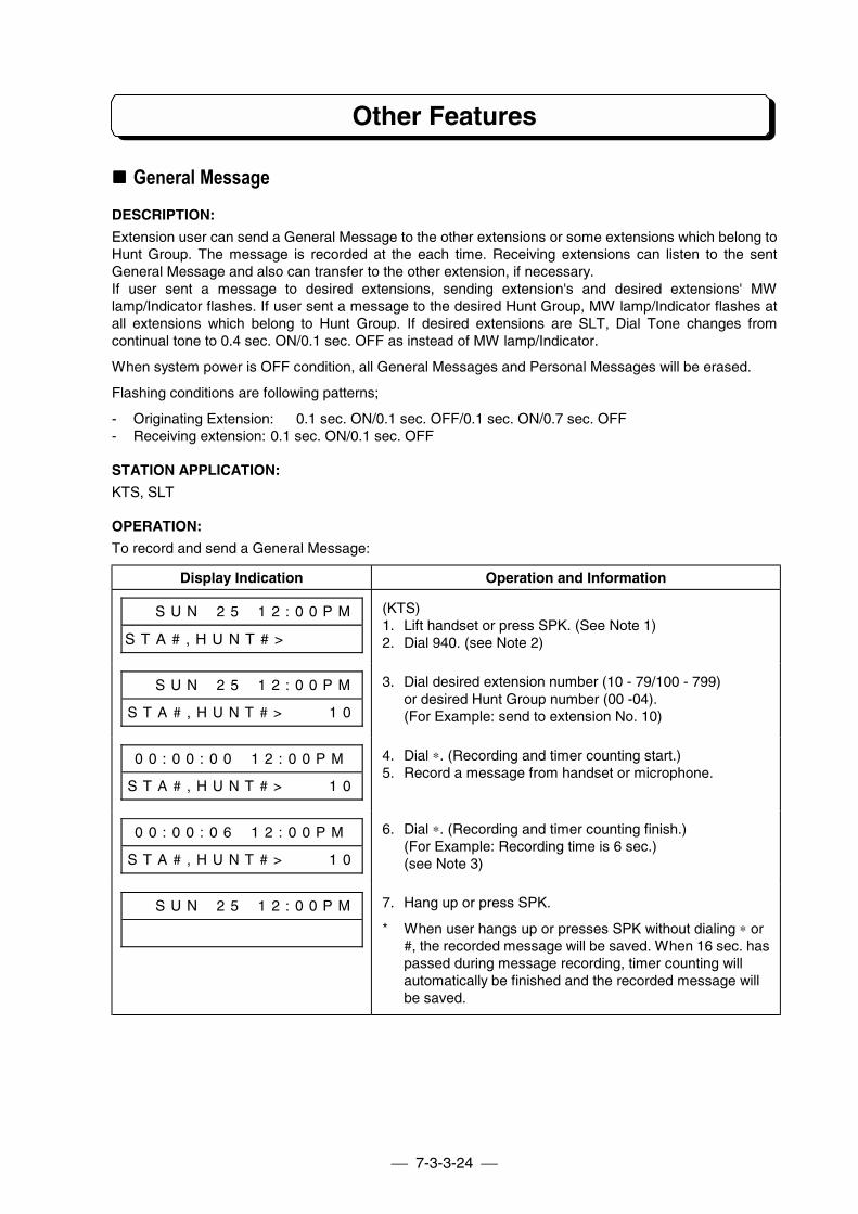
7-3-3-24
Other Features
!!!! General MessageDESCRIPTION:
Extension user can send a General Message to the other extensions or some extensions which belong toHunt Group. The message is recorded at the each time. Receiving extensions can listen to the sentGeneral Message and also can transfer to the other extension, if necessary.If user sent a message to desired extensions, sending extension's and desired extensions' MWlamp/Indicator flashes. If user sent a message to the desired Hunt Group, MW lamp/Indicator flashes atall extensions which belong to Hunt Group. If desired extensions are SLT, Dial Tone changes fromcontinual tone to 0.4 sec. ON/0.1 sec. OFF as instead of MW lamp/Indicator.
When system power is OFF condition, all General Messages and Personal Messages will be erased.
Flashing conditions are following patterns;
- Originating Extension: 0.1 sec. ON/0.1 sec. OFF/0.1 sec. ON/0.7 sec. OFF- Receiving extension: 0.1 sec. ON/0.1 sec. OFF
STATION APPLICATION:
KTS, SLT
OPERATION:
To record and send a General Message:
Display Indication Operation and Information
# # S U N # 2 5 # 1 2 : 0 0 P M
S T A # , H U N T # > # # # # #
(KTS)1. Lift handset or press SPK. (See Note 1)2. Dial 940. (see Note 2)
# # S U N # 2 5 # 1 2 : 0 0 P M
S T A # , H U N T # > # # # 1 0
3. Dial desired extension number (10 - 79/100 - 799)or desired Hunt Group number (00 -04).(For Example: send to extension No. 10)
0 0 : 0 0 : 0 0 # 1 2 : 0 0 P M
S T A # , H U N T # > # # # 1 0
4. Dial ∗. (Recording and timer counting start.)5. Record a message from handset or microphone.
0 0 : 0 0 : 0 6 # 1 2 : 0 0 P M
S T A # , H U N T # > # # # 1 0
6. Dial ∗. (Recording and timer counting finish.)(For Example: Recording time is 6 sec.)(see Note 3)
# # S U N # 2 5 # 1 2 : 0 0 P M 7. Hang up or press SPK.
* When user hangs up or presses SPK without dialing ∗ or#, the recorded message will be saved. When 16 sec. haspassed during message recording, timer counting willautomatically be finished and the recorded message willbe saved.
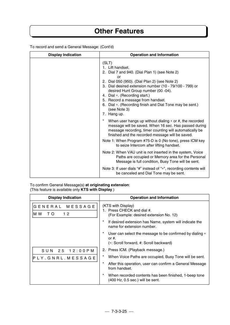
7-3-3-25
Other Features
To record and send a General Message: (Cont'd)
Display Indication Operation and Information
(SLT)1. Lift handset.2. Dial 7 and 940. (Dial Plan 1) (see Note 2)
or2. Dial 050 (950). (Dial Plan 2) (see Note 2)3. Dial desired extension number (10 - 79/100 - 799) or
desired Hunt Group number (00 -04).4. Dial ∗. (Recording start.)5. Record a message from handset.6. Dial ∗. (Recording finish and Dial Tone may be sent.)
(see Note 3)7. Hang up.
* When user hangs up without dialing ∗ or #, the recordedmessage will be saved. When 16 sec. Has passed duringmessage recording, timer counting will automatically befinished and the recorded message will be saved.
Note 1: When Program #75-D is 0 (No tone), press ICM keyto seize Intercom after lifting handset.
Note 2: When VAU unit is not inserted in the system, VoicePaths are occupied or Memory area for the PersonalMessage is full condition, Busy Tone will be sent.
Note 3: If user dials “#” instead of "∗", recording contents willbe canceled and Dial Tone may be sent.
To confirm General Message(s) at originating extension:(This feature is available only KTS with Display.)
Display Indication Operation and Information
G E N E R A L # M E S S A G E
M W # T O # # 1 2 # # # # # # #
(KTS with Display)1. Press CHECK and dial #.
(For Example: desired extension No. 12)
* If desired extension has Name, system will indicate thename for extension number.
* User can select the message to be confirmed by dialing ∗or #.(∗: Scroll forward, #: Scroll backward)
# # S U N # 2 5 # 1 2 : 0 0 P M
P L Y . G N R L . M E S S A G E
2. Press ICM. (Playback message.)
* When Voice Paths are occupied, Busy Tone will be sent.
* After this operation, user can confirm a General Messagefrom handset.
* When recorded contents has been finished, 1-beep tone(400 Hz, 0.5 sec.) will be sent.
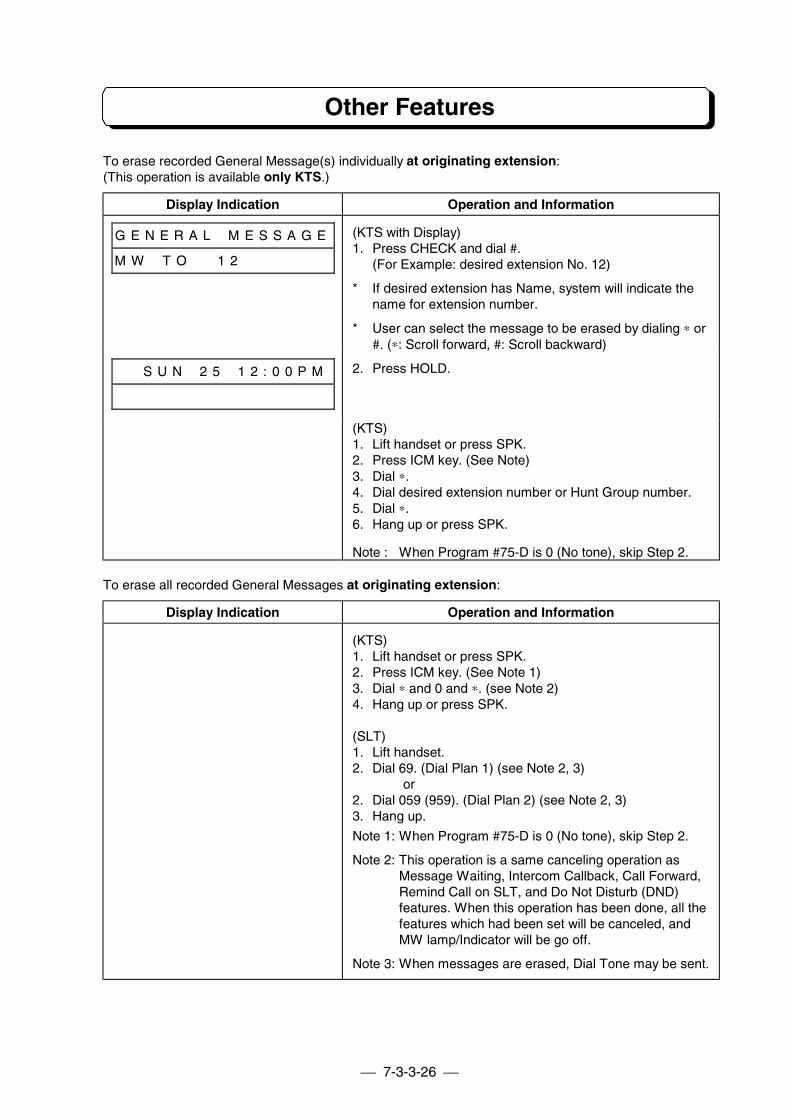
7-3-3-26
Other Features
To erase recorded General Message(s) individually at originating extension:(This operation is available only KTS.)
Display Indication Operation and Information
G E N E R A L # M E S S A G E
M W # T O # # 1 2 # # # # # # #
(KTS with Display)1. Press CHECK and dial #.
(For Example: desired extension No. 12)
* If desired extension has Name, system will indicate thename for extension number.
* User can select the message to be erased by dialing ∗ or#. (∗: Scroll forward, #: Scroll backward)
# # S U N # 2 5 # 1 2 : 0 0 P M 2. Press HOLD.
(KTS)1. Lift handset or press SPK.2. Press ICM key. (See Note)3. Dial ∗.4. Dial desired extension number or Hunt Group number.5. Dial ∗.6. Hang up or press SPK.
Note : When Program #75-D is 0 (No tone), skip Step 2.
To erase all recorded General Messages at originating extension:
Display Indication Operation and Information
(KTS)1. Lift handset or press SPK.2. Press ICM key. (See Note 1)3. Dial ∗ and 0 and ∗. (see Note 2)4. Hang up or press SPK.
(SLT)1. Lift handset.2. Dial 69. (Dial Plan 1) (see Note 2, 3)
or2. Dial 059 (959). (Dial Plan 2) (see Note 2, 3)3. Hang up.
Note 1: When Program #75-D is 0 (No tone), skip Step 2.
Note 2: This operation is a same canceling operation asMessage Waiting, Intercom Callback, Call Forward,Remind Call on SLT, and Do Not Disturb (DND)features. When this operation has been done, all thefeatures which had been set will be canceled, andMW lamp/Indicator will be go off.
Note 3: When messages are erased, Dial Tone may be sent.
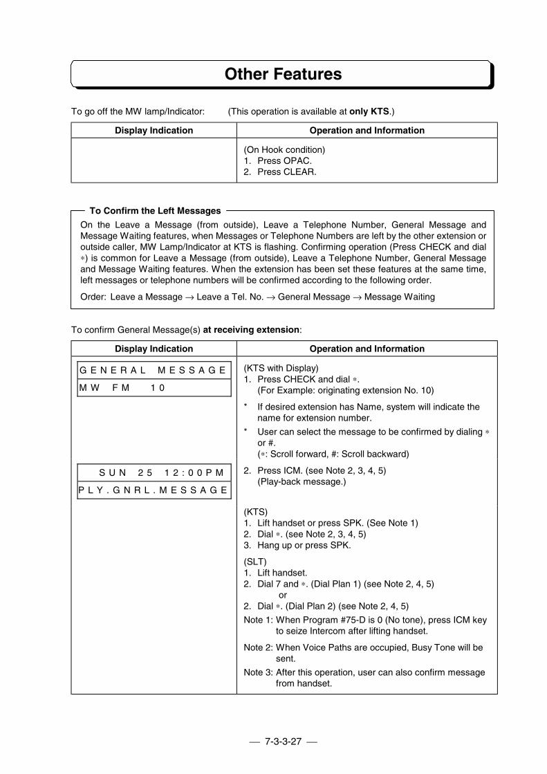
7-3-3-27
Other Features
To go off the MW lamp/Indicator: (This operation is available at only KTS.)
Display Indication Operation and Information
(On Hook condition)1. Press OPAC.2. Press CLEAR.
To Confirm the Left Messages
On the Leave a Message (from outside), Leave a Telephone Number, General Message andMessage Waiting features, when Messages or Telephone Numbers are left by the other extension oroutside caller, MW Lamp/Indicator at KTS is flashing. Confirming operation (Press CHECK and dial∗) is common for Leave a Message (from outside), Leave a Telephone Number, General Messageand Message Waiting features. When the extension has been set these features at the same time,left messages or telephone numbers will be confirmed according to the following order.
Order: Leave a Message → Leave a Tel. No. → General Message → Message Waiting
To confirm General Message(s) at receiving extension:
Display Indication Operation and Information
G E N E R A L # M E S S A G E
M W # F M # # 1 0 # # # # # # #
(KTS with Display)1. Press CHECK and dial ∗.
(For Example: originating extension No. 10)
* If desired extension has Name, system will indicate thename for extension number.
* User can select the message to be confirmed by dialing ∗or #.(∗: Scroll forward, #: Scroll backward)
# # S U N # 2 5 # 1 2 : 0 0 P M
P L Y . G N R L . M E S S A G E
2. Press ICM. (see Note 2, 3, 4, 5)(Play-back message.)
(KTS)1. Lift handset or press SPK. (See Note 1)2. Dial ∗. (see Note 2, 3, 4, 5)3. Hang up or press SPK.
(SLT)1. Lift handset.2. Dial 7 and ∗. (Dial Plan 1) (see Note 2, 4, 5)
or2. Dial ∗. (Dial Plan 2) (see Note 2, 4, 5)
Note 1: When Program #75-D is 0 (No tone), press ICM keyto seize Intercom after lifting handset.
Note 2: When Voice Paths are occupied, Busy Tone will besent.
Note 3: After this operation, user can also confirm messagefrom handset.
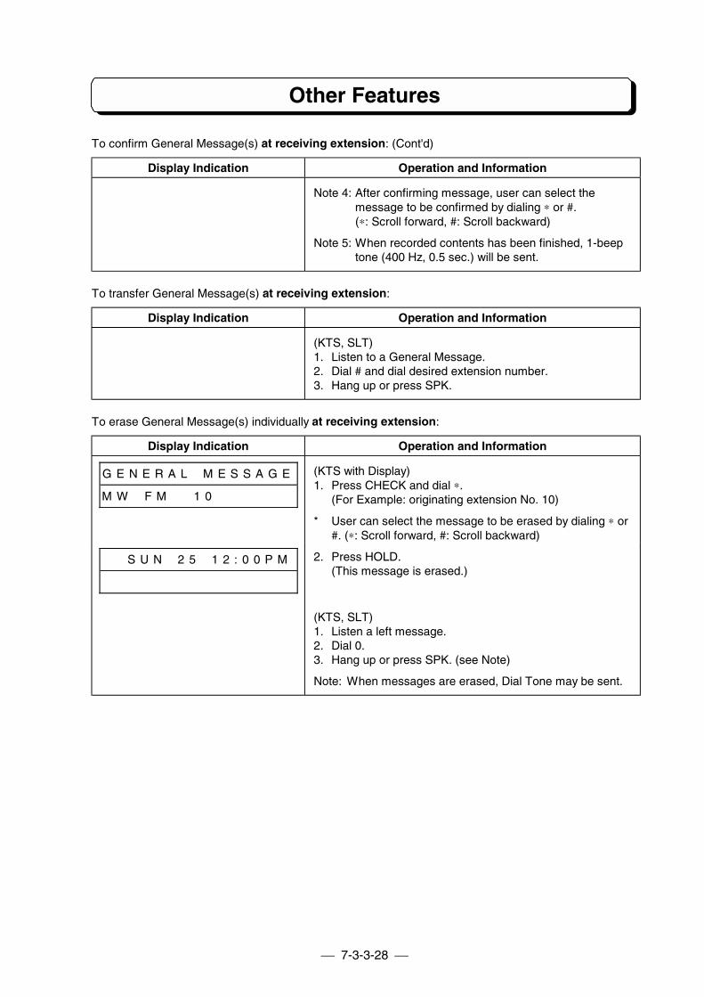
7-3-3-28
Other Features
To confirm General Message(s) at receiving extension: (Cont'd)
Display Indication Operation and Information
Note 4: After confirming message, user can select themessage to be confirmed by dialing ∗ or #.(∗: Scroll forward, #: Scroll backward)
Note 5: When recorded contents has been finished, 1-beeptone (400 Hz, 0.5 sec.) will be sent.
To transfer General Message(s) at receiving extension:
Display Indication Operation and Information
(KTS, SLT)1. Listen to a General Message.2. Dial # and dial desired extension number.3. Hang up or press SPK.
To erase General Message(s) individually at receiving extension:
Display Indication Operation and Information
G E N E R A L # M E S S A G E
M W # F M # # 1 0 # # # # # # #
(KTS with Display)1. Press CHECK and dial ∗.
(For Example: originating extension No. 10)
* User can select the message to be erased by dialing ∗ or#. (∗: Scroll forward, #: Scroll backward)
# # S U N # 2 5 # 1 2 : 0 0 P M 2. Press HOLD.(This message is erased.)
(KTS, SLT)1. Listen a left message.2. Dial 0.3. Hang up or press SPK. (see Note)
Note: When messages are erased, Dial Tone may be sent.
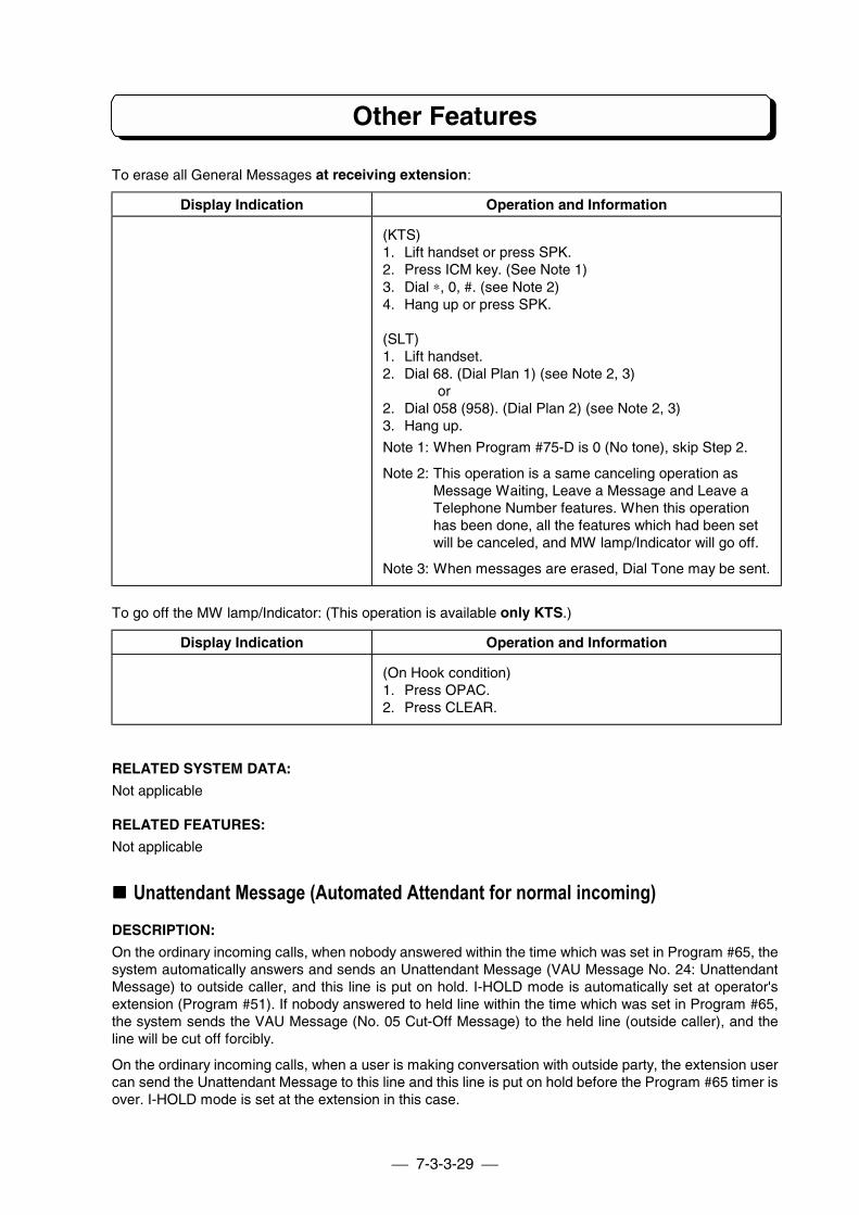
7-3-3-29
Other Features
To erase all General Messages at receiving extension:
Display Indication Operation and Information
(KTS)1. Lift handset or press SPK.2. Press ICM key. (See Note 1)3. Dial ∗, 0, #. (see Note 2)4. Hang up or press SPK.
(SLT)1. Lift handset.2. Dial 68. (Dial Plan 1) (see Note 2, 3)
or2. Dial 058 (958). (Dial Plan 2) (see Note 2, 3)3. Hang up.
Note 1: When Program #75-D is 0 (No tone), skip Step 2.
Note 2: This operation is a same canceling operation asMessage Waiting, Leave a Message and Leave aTelephone Number features. When this operationhas been done, all the features which had been setwill be canceled, and MW lamp/Indicator will go off.
Note 3: When messages are erased, Dial Tone may be sent.
To go off the MW lamp/Indicator: (This operation is available only KTS.)
Display Indication Operation and Information
(On Hook condition)1. Press OPAC.2. Press CLEAR.
RELATED SYSTEM DATA:
Not applicable
RELATED FEATURES:
Not applicable
!!!! Unattendant Message (Automated Attendant for normal incoming)DESCRIPTION:
On the ordinary incoming calls, when nobody answered within the time which was set in Program #65, thesystem automatically answers and sends an Unattendant Message (VAU Message No. 24: UnattendantMessage) to outside caller, and this line is put on hold. I-HOLD mode is automatically set at operator'sextension (Program #51). If nobody answered to held line within the time which was set in Program #65,the system sends the VAU Message (No. 05 Cut-Off Message) to the held line (outside caller), and theline will be cut off forcibly.
On the ordinary incoming calls, when a user is making conversation with outside party, the extension usercan send the Unattendant Message to this line and this line is put on hold before the Program #65 timer isover. I-HOLD mode is set at the extension in this case.
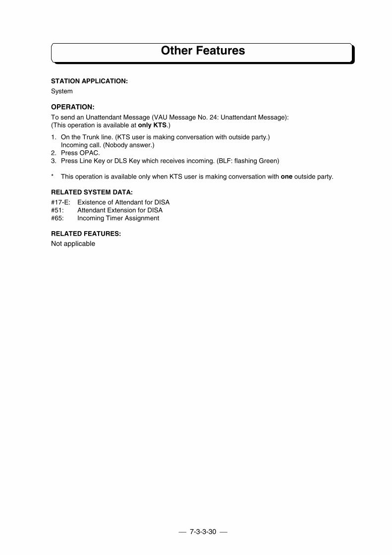
7-3-3-30
Other Features
STATION APPLICATION:
System
OPERATION:To send an Unattendant Message (VAU Message No. 24: Unattendant Message):(This operation is available at only KTS.)
1. On the Trunk line. (KTS user is making conversation with outside party.)Incoming call. (Nobody answer.)
2. Press OPAC.3. Press Line Key or DLS Key which receives incoming. (BLF: flashing Green)
* This operation is available only when KTS user is making conversation with one outside party.
RELATED SYSTEM DATA:
#17-E: Existence of Attendant for DISA#51: Attendant Extension for DISA#65: Incoming Timer Assignment
RELATED FEATURES:
Not applicable
PART 8
HOW TO USE FORSINGLE LINE TELEPHONE
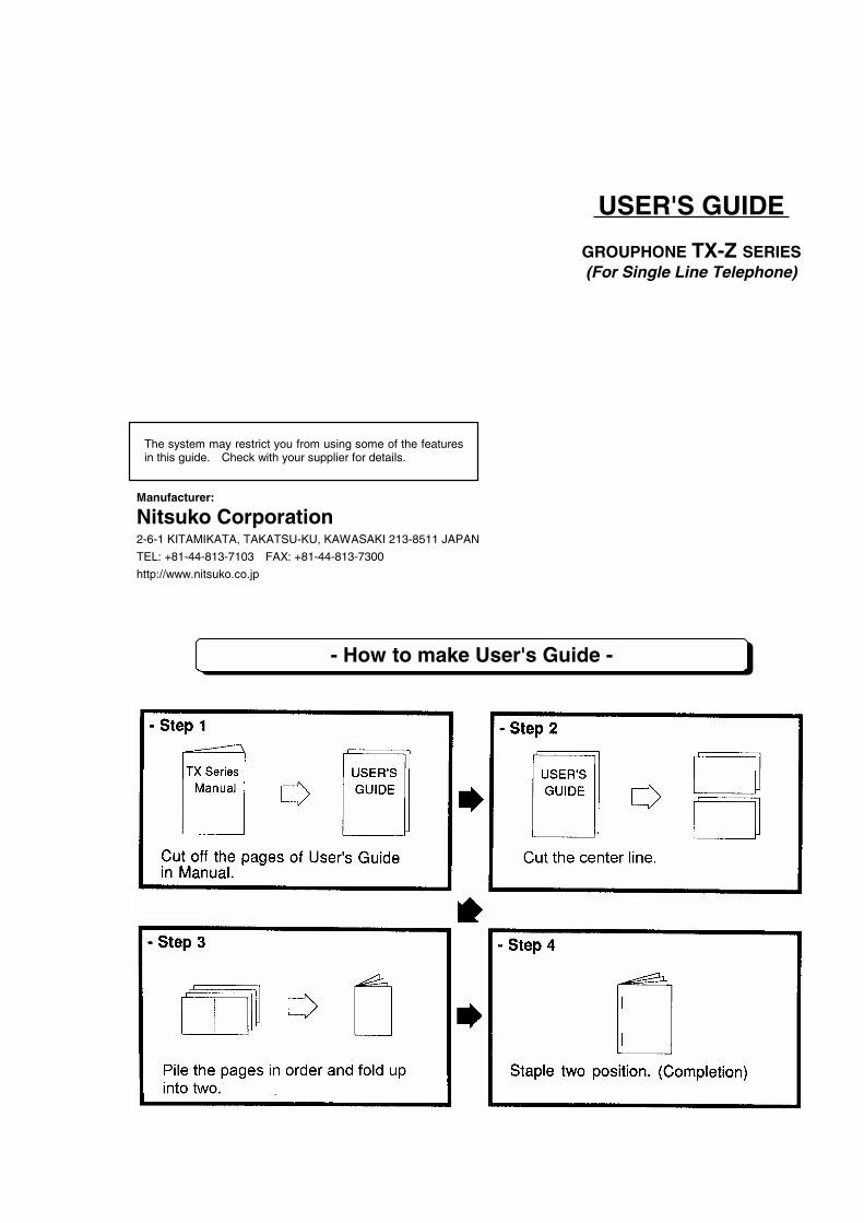
USER'S GUIDE
GROUPHONE TX-Z SERIES(For Single Line Telephone)
Manufacturer:
Nitsuko Corporation2-6-1 KITAMIKATA, TAKATSU-KU, KAWASAKI 213-8511 JAPAN
TEL: +81-44-813-7103 FAX: +81-44-813-7300
http://www.nitsuko.co.jp
- How to make User's Guide -
The system may restrict you from using some of the featuresin this guide. Check with your supplier for details.
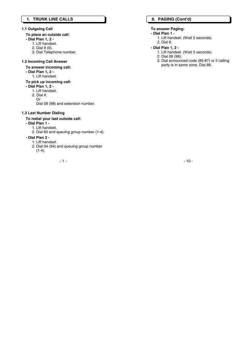
1. TRUNK LINE CALLS
1.1 Outgoing Call
To place an outside call:- Dial Plan 1, 2 -
1. Lift handset.2. Dial 9 (0).3. Dial Telephone number.
1.2 Incoming Call Answer
To answer incoming call:- Dial Plan 1, 2 -
1. Lift handset.
To pick up incoming call:- Dial Plan 1, 2 -
1. Lift handset.2. Dial #.
OrDial 08 (98) and extension number.
1.3 Last Number Dialing
To redial your last outside call:- Dial Plan 1 -
1. Lift handset.2. Dial 60 and queuing group number (1-4).
- Dial Plan 2 -1. Lift handset.2. Dial 04 (94) and queuing group number
(1-4).
8. PAGING (Cont'd)
To answer Paging:- Dial Plan 1 -
1. Lift handset. (Wait 5 seconds)2. Dial 8.
- Dial Plan 1, 2 -1. Lift handset. (Wait 5 seconds)2. Dial 08 (98),3. Dial announced code (80-87) or if calling
party is in same zone, Dial 88.
- 1 - - 10 -
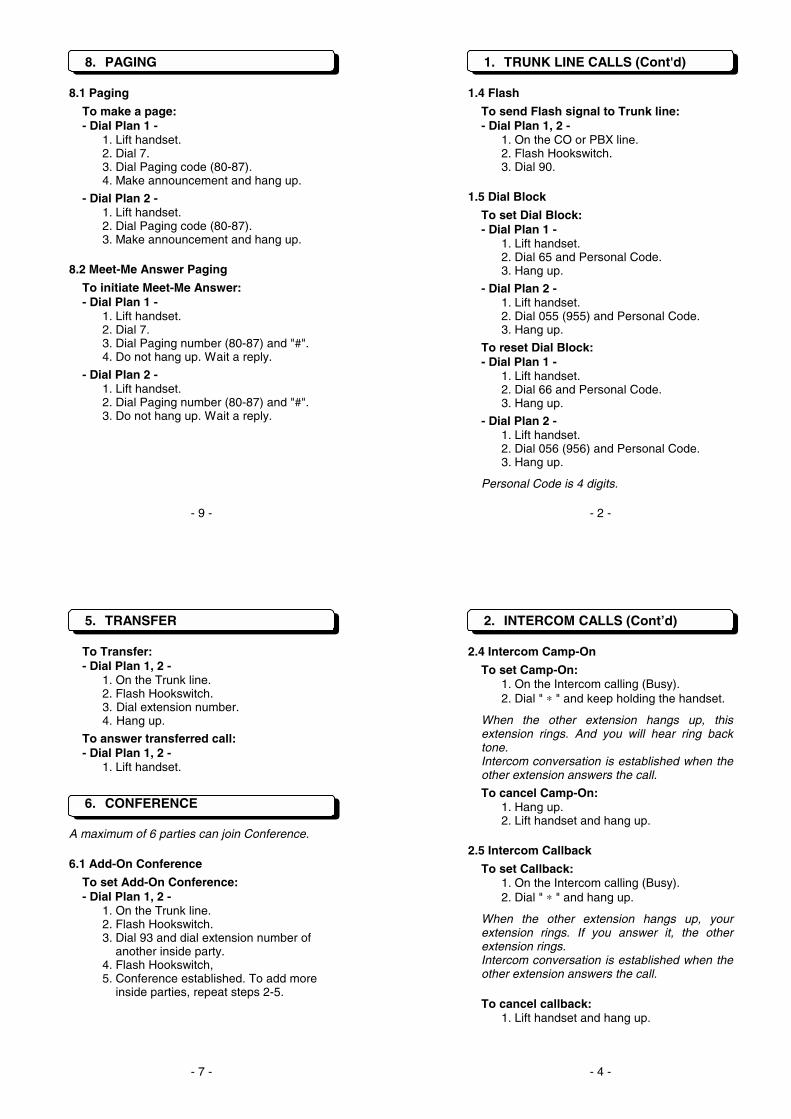
8. PAGING
8.1 Paging
To make a page:- Dial Plan 1 -
1. Lift handset.2. Dial 7.3. Dial Paging code (80-87).4. Make announcement and hang up.
- Dial Plan 2 -1. Lift handset.2. Dial Paging code (80-87).3. Make announcement and hang up.
8.2 Meet-Me Answer Paging
To initiate Meet-Me Answer:- Dial Plan 1 -
1. Lift handset.2. Dial 7.3. Dial Paging number (80-87) and "#".4. Do not hang up. Wait a reply.
- Dial Plan 2 -1. Lift handset.2. Dial Paging number (80-87) and "#".3. Do not hang up. Wait a reply.
1. TRUNK LINE CALLS (Cont'd)
1.4 Flash
To send Flash signal to Trunk line:- Dial Plan 1, 2 -
1. On the CO or PBX line.2. Flash Hookswitch.3. Dial 90.
1.5 Dial Block
To set Dial Block:- Dial Plan 1 -
1. Lift handset.2. Dial 65 and Personal Code.3. Hang up.
- Dial Plan 2 -1. Lift handset.2. Dial 055 (955) and Personal Code.3. Hang up.
To reset Dial Block:- Dial Plan 1 -
1. Lift handset.2. Dial 66 and Personal Code.3. Hang up.
- Dial Plan 2 -1. Lift handset.2. Dial 056 (956) and Personal Code.3. Hang up.
Personal Code is 4 digits.
- 9 - - 2 -
5. TRANSFER
To Transfer:- Dial Plan 1, 2 -
1. On the Trunk line.2. Flash Hookswitch.3. Dial extension number.4. Hang up.
To answer transferred call:- Dial Plan 1, 2 -
1. Lift handset.
6. CONFERENCE
A maximum of 6 parties can join Conference.
6.1 Add-On Conference
To set Add-On Conference:- Dial Plan 1, 2 -
1. On the Trunk line.2. Flash Hookswitch.3. Dial 93 and dial extension number of
another inside party.4. Flash Hookswitch,5. Conference established. To add more
inside parties, repeat steps 2-5.
2. INTERCOM CALLS (Cont’d)
2.4 Intercom Camp-On
To set Camp-On:1. On the Intercom calling (Busy).2. Dial " ∗ " and keep holding the handset.
When the other extension hangs up, thisextension rings. And you will hear ring backtone.Intercom conversation is established when theother extension answers the call.
To cancel Camp-On:1. Hang up.2. Lift handset and hang up.
2.5 Intercom Callback
To set Callback:1. On the Intercom calling (Busy).2. Dial " ∗ " and hang up.
When the other extension hangs up, yourextension rings. If you answer it, the otherextension rings.Intercom conversation is established when theother extension answers the call.
To cancel callback:1. Lift handset and hang up.
- 7 - - 4 -
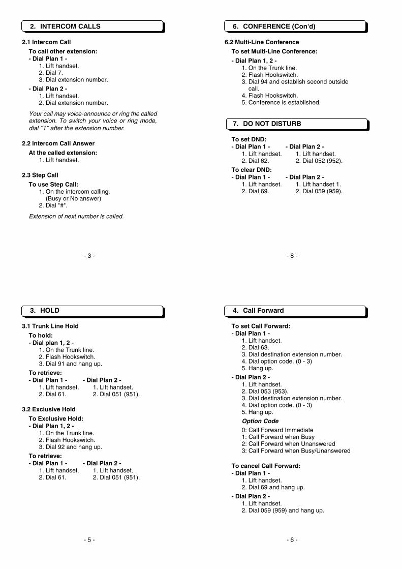
2. INTERCOM CALLS
2.1 Intercom Call
To call other extension:- Dial Plan 1 -
1. Lift handset.2. Dial 7.3. Dial extension number.
- Dial Plan 2 -1. Lift handset.2. Dial extension number.
Your call may voice-announce or ring the calledextension. To switch your voice or ring mode,dial ″1″ after the extension number.
2.2 Intercom Call Answer
At the called extension:1. Lift handset.
2.3 Step Call
To use Step Call:1. On the intercom calling.
(Busy or No answer)2. Dial "#".
Extension of next number is called.
6. CONFERENCE (Con'd)
6.2 Multi-Line Conference
To set Multi-Line Conference:
- Dial Plan 1, 2 -1. On the Trunk line.2. Flash Hookswitch.3. Dial 94 and establish second outside
call.4. Flash Hookswitch.5. Conference is established.
7. DO NOT DISTURB
To set DND:- Dial Plan 1 - - Dial Plan 2 -
1. Lift handset. 1. Lift handset.2. Dial 62. 2. Dial 052 (952).
To clear DND:- Dial Plan 1 - - Dial Plan 2 -
1. Lift handset. 1. Lift handset 1.2. Dial 69. 2. Dial 059 (959).
- 3 - - 8 -
3. HOLD
3.1 Trunk Line Hold
To hold:- Dial plan 1, 2 -
1. On the Trunk line.2. Flash Hookswitch.3. Dial 91 and hang up.
To retrieve:- Dial Plan 1 - - Dial Plan 2 -
1. Lift handset. 1. Lift handset.2. Dial 61. 2. Dial 051 (951).
3.2 Exclusive Hold
To Exclusive Hold:- Dial Plan 1, 2 -
1. On the Trunk line.2. Flash Hookswitch.3. Dial 92 and hang up.
To retrieve:- Dial Plan 1 - - Dial Plan 2 -
1. Lift handset. 1. Lift handset.2. Dial 61. 2. Dial 051 (951).
4. Call Forward
To set Call Forward:- Dial Plan 1 -
1. Lift handset.2. Dial 63.3. Dial destination extension number.4. Dial option code. (0 - 3)5. Hang up.
- Dial Plan 2 -1. Lift handset.2. Dial 053 (953).3. Dial destination extension number.4. Dial option code. (0 - 3)5. Hang up.
Option Code0: Call Forward Immediate1: Call Forward when Busy2: Call Forward when Unanswered3: Call Forward when Busy/Unanswered
To cancel Call Forward:- Dial Plan 1 -
1. Lift handset.2. Dial 69 and hang up.
- Dial Plan 2 -1. Lift handset.2. Dial 059 (959) and hang up.
- 5 - - 6 -

Manufacturer:
Nitsuko Corporation2-6-1 KITAMIKATA, TAKATSU-KU, KAWASAKI 213-8511 JAPANTEL: +81-44-813-7104 FAX: +81-44-813-7300http://www.nitsuko.co.jp