Embed Size (px)
Citation preview

Manufactured byK & W Mfg. Co. Inc., Corona, California
Installation & Operation InstructionsFor Gas Barbecues Models 5453 and 5457

1
A Note to YouThank you for buying a Flame-Broil barbecue grill. To ensure that you enjoy your barbecue equipment for manyyears, we developed these instructions. They contain valuable information about how to install, operate andmaintain your barbecue equipment. Please read them carefully.
Keep this booklet and your sales receipt together in a safe place for future reference. It is important for you tosave your sales receipt showing the date of purchase. Proof of purchase will assure you of warranty service.
If you need assistance or service, you can reach us at:
K & W Mfg. Co., Inc.23107 Temescal Canyon RoadCorona CA 92883-5045Phone: 909-277-3300FAX: 909-277-2070www.k-and-w-mfg.com
Happy Barbecuing!
Limited WarrantyK & W Mfg. Co., Inc. warrants Flame-Broil Barbecue Equipment to be free from defects in design, materials, andworkmanship at the time of manufacture.
For a period of five (5) years following purchase, K & W Mfg. Co., Inc. will repair or replace, at the discretion ofK & W Mfg. Co., Inc., any Flame-Broil Barbecue unit found to be defective by K & W Mfg. Co., Inc. or theirauthorized representative. This warranty does not cover the normal wear and tear that occurs from operation ofthe unit, nor does it including neglect or abuse. The Flame-Broil Barbecue unit must be installed and operated inaccordance with the installation and operating instructions of K & W Mfg. Co., Inc., and any local area buildingand fire codes. K & W Mfg. Co., Inc. shall not be responsible for any indirect, incidental, or other damage.
In order claim remedy under the five-year warranty, the unit must be returned to the factory, at the owner’sexpense, with a copy of the purchase receipt. If the unit is found to be defective, K & W Mfg. Co., Inc. will repairor replace the unit at their discretion, and return the unit to the owner at the company’s expense.
At any time, K & W Mfg. Co., Inc. will repair or replace any Flame-Broil Barbecue unit, returned to the factory atthe owner’s cost, for a cost of no more that half of the current suggested retail price of the most similar currentmodel.
Unpacking your BarbecueWhen you unpack your barbecue unit, you should find:
� The main body of the barbecue unit with the burner(s) installed� A drip tray at the bottom of the unit� A box inserted into the inner liner of the barbecue unit. This box should contain:
� These instructions� Two small hex-head orifices for converting from natural gas to propane (LP).� Two smaller cooking grills� One larger briquet grate� Three or four bags of stainless steel Broilettes

2
1 Installation
1.1 Setting up your stand or enclosureFlame-Broil barbecue equipment may be installed in many different types of enclosures or stands. If you areplanning to build a permanent enclosure and/or change your gas plumbing, it is highly recommended that youcheck with your local building department concerning building codes and permits. The following diagram willprovide you with the dimensions your equipment needs to fit its enclosure or stand.
1.1.1 Combustible Materials
Our barbecue units are intended for use in masonry or other fireproof locations. They are not insulated. Theyshould never be in contact with any combustible materials.
While operating your barbecue equipment, you should be at least 2 feet from any combustible house sidings. Inaddition, you should never operate your barbecue equipment under a roof overhang or patio cover made fromcombustible materials.
1.1.2 Drainage
Allowing water to pool in and around your barbecue equipment will increase the normal wear and tear to thecomponents, and lower their life expectancy. We recommend that you provide for drainage when building yourenclosure so that water will not pool underneath the barbecue, or inside the enclosure.

3
1.1.3 Ventilation
Blockage of fresh airflow into and around yourbarbecue equipment will cause overheating, poorcombustion and possible damage to components.There is an air space at the bottom of the barbecueunits, below the face. This air space must remainopen for your barbecue equipment to operate properly.
Our barbecues are also designed to vent though thecooking grill area. Therefore, air must be allowed toflow though the top of the unit. Only use a Flame-Broilbarbecue accessory to cover the cooking grill area.
CAUTION: Propane, also known as LP, is a gas that is heavier than the surrounding air. You should not storeyour propane bottle in an area that can trap any escaping gas. This means that your storage area must bevented at the level of the base of your tank.
1.2 Gas ConnectionsPlease study this connection information carefully. If you do not feel confident about making these connectionsyourself, please get help from a professional plumber or gas appliance installer before proceeding.
Be sure to use pipe tape or pipe joint compound approved for gas when making your connections. Check allconnections for leaks with a soapy solution (50% water / 50% detergent) before lighting the barbecue unit for thefirst time. Bubbles indicate a leak that must be repaired before proceeding.
We recommend that you remove the face of the unit for easier access. Be sure to remove all of the loosecomponents and accessories from the unit. Next, you remove the knobs by pulling them straight out from theface. Then, remove the four screws retaining the face to the frame. Carefully lift the face away from the frame.(Occasionally, we need to add spacers between the face and the frame to ensure that the cooking grills will fitcorrectly. Be sure to save any spacers you may find there.)

4
1.2.1 Permanent Gas Connection
Standard 1/2 in. iron gas pipe is recommended to make the connection from your household gas supply to yourbarbecue equipment. A shut-off valve in the gas line is recommended for safety and convenience. If thebarbecue unit is accessible to children, a shut-off valve with a removable key is highly recommended.
Stainless steel flexible connectors may be used for difficult locations. A 7/8 in. outside diameter connector is therecommended size. Smaller sizes may cause a gas flow restriction. This problem is usually indicated by awhistling sound in the gas line, and not enough heat available for cooking. The barbecue manifold will require a1/2 in. female end fitting.

5
1.2.2 Propane (LP) Bottle Connection
You must use a fuel pressure regulator with your propane bottle because the gas is stored under pressure. Werecommend using iron gas pipe to extend outside of the body of your unit before connecting to the hose andregulator.
CAUTION: Propane, also known as LP, is a gas that is heavier than the surrounding air. You should not storeyour propane bottle in an area that can trap any escaping gas. This means that your storage area must bevented at the level of the base of your tank.
1.3 Natural Gas to Propane (LP) ConversionYour barbecue equipment normally comes from the factoryready to use natural gas.To use propane, you need to change the orifice on your gasvalve(s). The orifice is on the end of the valve opposite fromthe stem where the control knob mounts.
You will need to slide the venturi air shutter from over theorifice, and move it out of the way. Using a 1/4 inch wrench,remove the natural gas orifice and replace it with the LPorifice that came with your equipment. Replace the venturi bysliding the air shutter back over the orifice end of the valve.
6
1.4 Adjusting the Fuel MixtureAfter you have completed your gas connections, you should check for the proper fuel and air mixture. (Pleaseremember to check all of the gas connections for leaks with a50/50 soap bubble solution.) With the face removed,temporarily replace the control knobs. Turn the gas on and lightthe BBQ. (See the lighting instructions in the Operationsection.) If the flames burn with a slightly yellow tip, and do notlift from the burner ports, no further adjustment is necessary.
To adjust combustion, loosen the air shutter set screw. Forexcessive yellow flame, you turn the air shutter to increase theair shutter opening. For flame that lifts off the burner ports, youturn air shutter to decrease the air shutter opening. Afteradjusting the fuel mixture, tighten the air shutter screw.
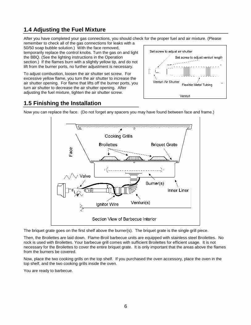
1.5 Finishing the InstallationNow you can replace the face. (Do not forget any spacers you may have found between face and frame.)
The briquet grate goes on the first shelf above the burner(s). The briquet grate is the single grill piece.
Then, the Broilettes are laid down. Flame-Broil barbecue units are equipped with stainless steel Broilettes. Norock is used with Broilettes. Your barbecue grill comes with sufficient Broilettes for efficient usage. It is notnecessary for the Broilettes to cover the entire briquet grate. It is only important that the areas above the flamesfrom the burners be covered.
Now, place the two cooking grills on the top shelf. If you purchased the oven accessory, place the oven in thetop shelf, and the two cooking grills inside the oven.
You are ready to barbecue.

7
2 Operation
CAUTION: Do not leave your barbecue equipment unattended after the burner has been lit. Most fires andaccidents occur when the unit has been left unattended while the flame is burning.
2.1 Lighting the BurnerYour barbecue equipment will have several knobs on the facefor controlling the gas and lighting the gas. The gas controlknobs are labeled “PUSH TO TURN” in the center, “OFF” atthe twelve o’clock position, “HIGH” at the three o’clock positionand “MED LOW” at the six o’clock position. The rotary ignitorknobs are the smaller knobs with the directional arrows.
The gas control knob has a “click” stop at “OFF” position. Tostart the gas, the knob is depressed and turnedcounterclockwise to the “HIGH” position. There is another“click” stop at the “HIGH” position. To shut the gas off,depress the knob and turn clockwise to the “OFF” position.
The rotary ignitor generates a spark as you turn the knob, andthis spark lights the gas. It is very important to only turn the rotary ignitor knob clockwise, in the direction of thearrows. You will damage the ignitor by turning the knob in the opposite direction.
2.1.1 To light the burner with the rotary ignitor
Turn the gas on and immediately begin turning the rotary ignitor knob. If the burner does not light after a fewturns of the ignitor knob, turn off the gas. Allow any gas to dissipate for a few minutes. Repeat this lightingprocedure.If the unit still does not light, use the trouble-shooting section on lighting. If you have determined that the ignitor isnot functioning, you may use a match for lighting until you have a chance to clean or replace the ignitor.
2.1.2 To light the burner with a match,
Strike the match first. Drop the lit match into the unit, close to the burner’s edge. Make sure the match stayslit, and turn on the gas. The burner should light within 5 seconds of turning on the gas. If the burner does notlight, turn off the gas. Use the trouble-shooting section to check for an obstruction in your gas supply.
If you still cannot light the burner, please contact us for help.
2.2 Adjusting the FlameThe highest flame setting is with the gas control knob set at the “HIGH” position. To adjust to a lower flame,depress the gas control knob and turn counterclockwise. The lowest flame setting is at the “MED LOW” position.The flame will adjust between these two settings.
To turn off the flame, depress the gas control knob and turn clockwise to the “OFF” position.

8
2.3 Trouble-shootingHere are some of the common problems that sometimes occur with gas barbecue equipment. If these solutionsdo not solve your problem, please contact us for help.
2.3.1 It won’t light.
There are two possible reasons for the unit not to light.
a) The rotary ignitor isn’t sparking.
With the gas shut off, watch the electrode tip inside the gas collector boxwhile turning the ignitor knob. It may be necessary to use a small handmirror to see inside the collector box. A spark should jump from theelectrode tip to the inner roof of the collector box.
If there is no spark, follow the maintenance procedure for the rotaryignitor.
b) The gas is not reaching the ignitor collection box or the burner(s).
There is an obstruction somewhere in the gas supply.
� Check that the source of your gas supply is turned on at your shut-off valve or your propane bottle.� Check for any blockage of the gas control valve, or the venturi and burner. Follow the maintenance
procedure on cleaning the valve(s), burner(s) and venturi(s).� Check for any restriction in your gas supply lines. A common problem is to use a pipe or flexible
connector with a smaller diameter than recommended when installing the gas connections. Review thegas connection instructions in the Installation section.
2.3.2 It won’t get hot.
a) The LP gas valve orifice is being used when thebarbecue equipment is burning natural gas.
The table on the left gives the drill size of the holes in theorifice(s). If you do not have a drill set to test yourorifice(s), try comparing all of the orifices that came withyour equipment. The hole in the natural gas orifice(s) islarger than the hole in the LP orifice(s). If your barbecueequipment is burning natural gas, the orifice(s) with thelarger holes should be installed in the gas controlvalve(s).
b) An obstruction is partially blocking the gas supply to theburner(s).
� Check that the source of your gas supply is turned onat your shut-off valve or your propane bottle.
� Check for any blockage of the gas control valve, or the venturi and burner. Follow the maintenanceprocedure on cleaning the valve(s), burner(s) and venturi(s).
� Check for any restriction in your gas supply lines. A common problem is to use a pipe or flexibleconnector with a smaller diameter than recommended when installing the gas connections. Review thegas connection instructions in the Installation section.

9
2.3.3 It gets too hot.
The natural gas valve orifice is being used when thebarbecue equipment is burning LP (propane) gas. The tableon the left gives the drill size of the holes in the orifice(s). Ifyou do not have a drill set to test your orifice(s), try comparingall of the orifices that came with your equipment. The hole inthe natural gas orifice(s) is larger than the hole in the LPorifice(s). If your barbecue equipment is burning LP(propane) gas, the orifice(s) with the smaller holes should beinstalled in the gas control valve(s).
2.3.4 There is a whistling noise.
There is a restriction in your gas supply lines. A commonproblem is to use a pipe or flexible connector with a smallerdiameter than recommended when installing the gasconnections. Review the gas connection instructions in the Installation section.
2.3.5 Flames around the gas control knob.
This is known as a flashback fire. There is an obstruction in the venturi and/or the burner. This obstructioncauses gas to back up and escape out the venturi air shutter where it ignites when you light the unit. Follow themaintenance procedure on cleaning the burner(s) and venturis.

10
3 MaintenancePeriodic inspection and cleaning of your barbecue equipment will ensure its proper operation. The followingchecklist is recommended.
� Clean the cooking grills, broilettes and briquet grate.� Clean the burner(s), venturis and valves.� Clean the grill interior.� Check the rotary ignitor.� Reassemble and test.
If you live in an area where inclement weather prevents you from using your barbecue equipment during certaintimes of the year, it is a good idea to remove and store the unit. This practice will extend the life of yourequipment and its components. If you cannot remove the unit, try to cover it completely from the elements.
3.1 PreparationAlways shut off the gas supply at the source before doing any maintenance or repairs.
Many parts will have a greasy film or rusty residue. Wear protective clothing and protect the area around thebarbecue equipment.
Before removing any components, have a notebook handy to keep notes on the order and placement of theparts.
You will need:
� Bucket or small tub� Wire brush� Steel wool or nylon pad� Fine sandpaper or emery cloth� Toothpick or small piece of wire
� Philips screwdriver� 1/4 inch wrench� Putty knife or scraper� Strong detergent or degreaser� Rubbing Alcohol
� Vegetable oil� WD40 or similar lubricant� Venturi spider brush (optional)
3.2 Clean the Cooking Grills, Broilettes and Briquet GrateCooking grills are most efficiently and easily cleaned on an ongoing basis bysimply pre-heating the grill on high for 10 minutes before each use. Afterheating, scrubbing with a brass bristle brush to remove the loose residue, andthen carefully wipe down with a wet paper towel.Tip - Coating the cooking grills with vegetable oil before cooking helps preventthe food from sticking and makes cleaning easier.
For a thorough cleaning, remove and inspect the cooking grills. If you findbroken welds or excessive rust, you may opt to replace the grills. If thecooking grills are not too badly deteriorated, soak in a hot soapy water solutionto loosen accumulated grease (a degreaser may also be used), then scrub with a steel wool pad or a stiff nylonpad. Rinse thoroughly and lightly coat with vegetable oil before use.
Next, remove and inspect the stainless steel Broilettes. Any badly deterioratedones should be replaced. A light coating of rust is okay. Knock off any looserust or deposits with a wire brush. You may wash them if you desire.
Finally, inspect the briquet grate. This component is subject to very hightemperatures and will weaken and deteriorate over time. If the grate is verythin, or sags excessively, replace it with a new grate. Otherwise, knock off anyloose rust and scale with a wire brush.

11
3.3 Clean the Burner(s), Venturi(s) and Valve(s)At this point, you should remove the face of the unitfor easier access. Remove the knobs by pullingthem straight out from the face. Next, remove thefour screws retaining the face to the frame. Carefullylift the face away from the frame. (Occasionally, weneed to add spacers between the face and the frameto ensure that the cooking grills will fit correctly. Besure to save any spacers you may find there.)
The wire, which connects the rotary ignitor generatorto the collector box, is usually loosely wrappedaround the venturi tube. This wire must bedisconnected from the spark generator, andunwrapped from the venturi tube before the burner isremoved.
Carefully remove the burner(s) from the inner liningarea. With the model #5457, you may need to pry back the clips that hold the burners to the liner. Lightly brushthe burner with a wire brush to remove loose rust and scale. Inspect the burner for holes or split seams, andreplace if necessary. If the burner passes inspection, next inspect the venturi.
IT IS EXTREMELY IMPORTANT to clean the venturitubes of any obstructions, such as spider or insectwebs, etc. A small web can block the gas flow andcause poor burner performance or a flashback fire.A flexible spider brush is the best tool for cleaning theventuri tubes. Special care should be taken to makesure the brush passes through the entire venturitube, all the way to the burner.
If a spider brush is not available, you may flush outthe venturi with a strong flow of water from a gardenhose. Pay special attention to how the water exitsthe burner port holes, as clogged holes are easilyspotted. Clogged holes can be opened with an awlor piece of wire. Clogged holes can cause a grill tohave hot and cold spots because of uneven flamecharacteristics.
The valves can now be checked. Temporarily slide thevalve knobs back onto the valve stems. The knobsshould depress, turn and release (pop up) freely. If theyare sluggish, carefully spray a small amount of WD40 orsimilar lubricant onto the valve stem area. Work knobs afew times to distribute the lubricant. Valves that bindseverely should be replaced.
Small insects can also block the valve orifice, which willrestrict gas flow. Debris in the gas supply lines may alsoclog these tiny holes. So, remove the hex head orifice witha 1/4 inch wrench, and make sure the hole is completelyclean. Also, check the inner portion of the valve fromwhere the orifice was removed. Debris can be removedwith a small piece of wire or toothpick. Re-install orifices and tighten.

12
3.4 Clean the Grill InteriorFirst, protect the ignitor collector box with the electrode by covering it witha protective cloth or plastic, or aluminum foil.
Secondly, scrape off heavy grease or cooking debris accumulation with aputty knife or scraper. You can vacuum this debris with a shop vacuumcleaner, or brush it through the holes in the burner tray, at the bottom ofthe liner, onto the drip tray. When you are done, you should remove anddump the contents of the drip tray.
Lastly, scrub the interior with a strong detergent solution (a degreaser mayalso be used). Rinse, and let dry. Remove protective covers installedearlier.
3.5 Check the Rotary IgnitorThe ignitor sends a high voltage along the wire to the ignitor electrode inside thecollector box. The collector box collects a quantity of gas, which a spark lights.
Grease, dirt and/or rust on the electrode or the collector box can prevent theelectrode from sparking. Clean any dirt and grease with alcohol. Remove anyrust by lightly sanding with emery cloth or fine sandpaper.
Check that the electrode insulation isn't cracked or broken, and replace if it is.Cracks collect moisture that keeps the spark from getting to the electrode. It isnormal for the wire to fit loosely in the porcelain.
Check the ignitor wire for abrasions, cuts or burns in the insulation. Also, checkthat the wire is not broken inside the insulation. Replace if you find any of theseproblems. Check the wire connections for corrosion or looseness. Clean ortighten as needed.
3.6 Reassemble and TestReinstall the burner(s). Slide the venturi air shutterback over the orifice end of the valves. Re-wrap theignitor wire around the venturi and restore itsconnections. Turn the ignitor knob while watchingthe connections from the underside of the grill toassure the spark isn't jumping from a connection tothe grill body. Then, turn the ignitor knob whilewatching the inside of the collector box to assure thatthe spark is jumping from the electrode to the innerroof of the collector box. It may be necessary to usea small hand mirror to see inside the collector box.
Turn on the gas supply, and test light the burner(s).Review the section on adjusting the fuel mixture, andcheck your flame.
Now you can replace the face. (Do not forget anyspacers you may have found between face andframe.)
Replace the briquet grate and the broilettes. Distribute the broilettes evenly in the areas on the briquet gratesurface above the flames from the burners. This will help the grill cook at an overall even temperature.
Finally, you can replace the cooking grills. If you purchased the oven accessory, place the oven in the top shelf,and the two cooking grills inside the oven.
13
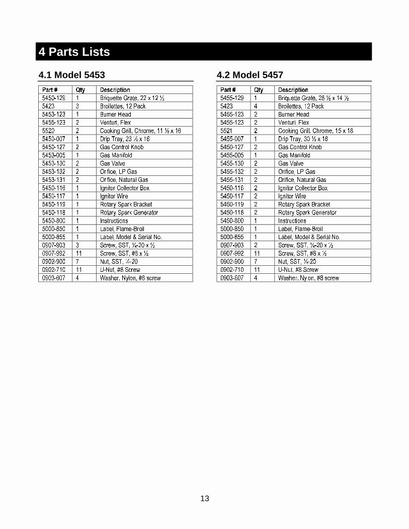
4 Parts Lists
4.1 Model 5453
���� � ��� ��� �� ��
�������� � ��� �� ��� � �� � �� �
���� � ��� �� �� �� ����
�������� � ��� � ��
�������� � � ���� � �
���� � !����" ���� !#�$ � �� � � �%
�������& � '( )�*� �� � � �%
�������& � ��� !����� +��,
�������� � ��� -��.���
�������� � ��� ���/
�������� � 0.� � 1� ���
�������� � 0.� � 2����� ���
�������% � 3"��� !��� ��� ���
�������& � 3"��� 4
�������� � 5���* 6(�� ���� �
�������7 � 5���* 6(�� � � ���
�����7�� � 3���������
�����7�� � 1�, �� ��$ ����
�����7�� � 1�, �� -�� � 8 6 �� 2�9
���&���� � 6� :� 66)� ;��� � �
���&���� �� 6� :� 66)� <7 � �
�������� & 2��� 66)� ;���
�����&�� �� =�2��� <7 6� :
�����%�& � 4��# � 2*���� <7 �� :
4.2 Model 5457
���� � ��� ��� �� ��
�������� � ��� �� ��� � �7 � � �� �
���� � ��� �� �� �� ����
�������� � ��� � ��
�������� � � ���� � �
���� � !����" ���� !#�$ � �� � �7
�������& � '( )�*� �� � � �7
�������& � ��� !����� +��,
�������� � ��� -��.���
�������� � ��� ���/
�������� � 0.� � 1� ���
�������� � 0.� � 2����� ���
�������% � 3"��� !��� ��� ���
�������& � 3"��� 4
�������� � 5���* 6(�� ���� �
�������7 � 5���* 6(�� � � ���
�����7�� � 3���������
�����7�� � 1�, �� ��$ ����
�����7�� � 1�, �� -�� � 8 6 �� 2�9
���&���� � 6� :� 66)� ;��� � �
���&���� �� 6� :� 66)� <7 � �
�������� & 2��� 66)� ;���
�����&�� �� =�2��� <7 6� :
�����%�& � 4��# � 2*���� <7 �� :