Embed Size (px)
Citation preview

Installation and Configuration Guide for Microsoft Exchange Server 2013
Designed for organizations implementing Exchange 2013 in a virtual environment
Includes step-by-step implementation guidance
Describes a highly available and site-resilient implementation
Includes sizing recommendations for servers, storage, and networking
Roland Mueller
Last update: 25 January 2016

2 Installation and Configuration Guide for Microsoft SharePoint Server 2013
Table of Contents
1 Introduction ............................................................................................... 4
2 Installation and configuration .................................................................. 5
3 Server installation ..................................................................................... 6
3.1 Hardware configuration ............................................................................................ 6
3.2 Windows OS installation and configuration .............................................................. 6
4 Networking ................................................................................................ 7
4.1 Using ISCLI to configure the CN4093 10 Gb Scalable Switch module .................... 9
4.2 Configuring the ISL and VLAG peer relationship ..................................................... 9 4.2.1 Configure vLAG peer health checks ........................................................................................... 11 4.2.2 Enable tagging on host ports ...................................................................................................... 11 4.2.3 Configure the VLANs .................................................................................................................. 11 4.2.4 Configure LACP teams and enable vLAG on the host connections .......................................... 13
4.3 Creating the NIC team and network adapters ........................................................ 14 4.3.1 Creating the NIC team and network adapters for the Hyper-V cluster servers ......................... 14
5 Storage networking ................................................................................ 18
5.1 Storage zoning ....................................................................................................... 18
5.2 Configuring the host bus adapters ......................................................................... 20
5.3 Enabling multipathing ............................................................................................. 21
5.4 Host definition on the Storwize V3700 ................................................................... 22
6 Storage partitioning ................................................................................ 26
6.1 Create storage pool ............................................................................................... 26
6.2 Create logical volumes ........................................................................................... 27
7 Creating a Windows cluster ................................................................... 31
7.1 Create the WSFC cluster ....................................................................................... 31
3 Installation and Configuration Guide for Microsoft SharePoint Server 2013
7.2 Adding the cluster shared volumes ........................................................................ 33
7.3 Configuring the cluster network .............................................................................. 36
8 Microsoft Hyper-V configuration ........................................................... 39
9 Creating a highly available VM for Exchange ...................................... 40
9.1 Creation of Exchange VMs .................................................................................... 40
9.2 Changing the VM save state on shut down for migration ....................................... 41
9.3 VM preferred owners ............................................................................................. 42
9.4 VM network configuration ...................................................................................... 44
9.5 Adding an additional drive for the Exchange install files ........................................ 45
10 Installing and configuring Exchange .................................................... 46
10.1 Active Directory requirements ................................................................................ 46
10.2 Installing software prerequisites ............................................................................. 46
10.3 Installing Exchange ................................................................................................ 47
10.4 Exchange 2013 post-installation configuration tasks ............................................. 51
References .................................................................................................... 52

4 Installation and Configuration Guide for Microsoft SharePoint Server 2013
1 Introduction This document provides information on how to implement the solution as described in the paper “Reference Architecture: Microsoft Exchange Server 2013” which is available from:
https://lenovopress.com/tips1308-microsoft-exchange-server-2013-ra
Whereas the reference architecture provides the planning, design considerations, and best practices for creating a Microsoft Exchange Server 2013 architecture, this document provides the steps necessary to configure and install the solution using Lenovo products.
The intended audience of this document is IT professionals, technical architects, and consultants to assist in planning, designing, and implementing the solution as described in the reference architecture.

5 Installation and Configuration Guide for Microsoft SharePoint Server 2013
2 Installation and configuration Using a set of test-proven planning and deployment techniques can contribute significantly to the successful deployment and operation of a virtualized Exchange Server 2013 environment that uses Windows Server Failover Clustering (WSFC) and Microsoft Hyper-V. Proper planning includes sizing resource requirements for servers (CPU and memory), storage (capacity and IOPS), and networking (bandwidth and VLAN assignment) to support the infrastructure. The sizing information, combined with industry-standard best practices, can be used to achieve optimal performance and growth headroom necessary for the life of the solution.
Configuration best practices and implementation guidelines, which aid in planning and configuration of the solution, are described in the following topics:
• 3 Server installation • 4 Networking • 5 Storage networking • 6 Storage partitioning • 7 Creating a Windows cluster • 8 Microsoft Hyper-V configuration • 9 Creating a highly available VM for Exchange • 10 Installing and configuring Exchange

6 Installation and Configuration Guide for Microsoft SharePoint Server 2013
3 Server installation Dual-socket Lenovo Flex System x240 M5 servers with the following configuration:
• 384 GB RAM • Two Intel Xeon E5-2697 v3 (Haswell) 2.6 GHz 14-core processors • One Flex System CN4052 2-port Virtual Fabric Adapter 5 • One Flex System FC3052 2-port 8gb Fibre Channel HBA
Setup of the server involves the installation and configuration of the following items:
• Windows Server 2012 R2 Datacenter edition • Networking • Storage
Windows Server 2012 R2 Datacenter edition allows unlimited Windows virtual machine (VM) rights on the host servers and is the preferred version for building private cloud configurations. Windows Server 2012 R2 Standard edition supports clustering as well, but provides licensing rights for only up to two Windows VMs and is intended for physical servers that are hosting few or no VMs.
3.1 Hardware configuration Before installing the Windows Server operating system, verify the following on each of the servers:
• Confirm that the Emulex network adapter and HBA are installed • Validate that firmware levels are consistent across all servers • Verify that the two local drives are configured as a RAID-1 array for the operating system
3.2 Windows OS installation and configuration Install Windows Server 2012 R2 Datacenter edition on the servers and then perform the following on each of the servers:
• Set your server name. • Run Windows Update to ensure that any new patches are installed. All the servers in a Windows.
Server failover cluster (WSFC) should have the same software updates (patches) and service packs. • Download and install the latest chipset driver. • Download and install the latest network adapter and HBA drivers from the Lenovo Support portal:
http://support.lenovo.com/us/en/products • Install the Emulex OneCommand Manager utility to provide additional insight to the converged
infrastructure. This utility is available from: http://emulex.com/downloads/emulex/drivers/windows/windows-server-2012-r2/management/
• Install the Hyper-V role on the servers. Because the servers use a virtual switch, this step is a prerequisite for configuring networking.
• Install the Failover Clustering feature. • After network configuration is complete, join the servers to the domain.

7 Installation and Configuration Guide for Microsoft SharePoint Server 2013
4 Networking This section describes the networking topology, virtual LAN (VLAN) definitions and includes instructions to correctly configure the network environment, as shown in Figure 1 below.
Figure 1. Network configuration
VLANs are used to provide logical isolation between the various data traffic.
All data traffic is over a single NIC team built using the Flex System CN4052 2-port Virtual Fabric Adapter 5 installed in each of the servers. The NIC team is created using the Windows Server 2012 R2 in-box NIC teaming feature, which provides fault tolerance and load balancing for the networks. The VLANs described in this section share the bandwidth of the single NIC team. Therefore, Quality of Service (QoS) will be applied from Windows to ensure each VLAN has available bandwidth.
The suggested VLANs are listed in Table 1.

8 Installation and Configuration Guide for Microsoft SharePoint Server 2013
Table 1. VLAN Definitions
VLAN ID Name Description
VLAN 70 Management Network A network used for host management, storage
management, and out-of-band communication to IMM
devices.
VLAN 60 Cluster Private Network A network reserved for cluster private (heartbeat and
cluster shared volume) communication between the
clustered Hyper-V host servers. There should be no IP
routing or default gateways for cluster private networks.
VLAN 50 Live Migration Network A network to support Live Migration for the management
cluster. There should be no routing on the live migration
VLAN.
VLAN 40 Cluster Public (Corporate
Network) / MAPI Traffic
A network reserved for connecting to the domain controller
and to the corporate network. MAPI traffic will use this
network.
VLAN 30 Exchange (Replication
Network)
A network for Exchange database replication.
VLAN 100 vLAG (Virtual Link
Aggregation Group)
A dedicated VLAN to support communication between
Server 1 and the switch ports that are configured as
vLAG/LACP (Link Aggregation Control Protocol) teams.
VLAN 200 vLAG A dedicated VLAN to support communication between
Server 2 and the switch ports that are configured as
vLAG/LACP teams.
VLAN 300 vLAG A dedicated VLAN to support communication between
Server 3 and the switch ports that are configured as
vLAG/LACP teams.
VLAN 4094 Inter-Switch Link (ISL) A dedicated VLAN to support the ISL trunk group between
the two switches. The spanning tree protocol should be
disabled on the trunk group VLAN.

9 Installation and Configuration Guide for Microsoft SharePoint Server 2013
4.1 Using ISCLI to configure the CN4093 10 Gb Scalable Switch module
Below are some examples of the ISCLI commands to setup and configure the Flex Fabric CN4093 10 Gb Converged Scalable Switch module. The commands below are for use with switches running Networking OS 7.2.2.0 software. If your switch has a different version, please refer to the applicable Application Guide for the appropriate commands. To download the CN4093 Application Guide, visit the following website: http://pic.dhe.ibm.com/infocenter/flexsys/information/topic/com.lenovo.acc.cn4093.doc/CN4093_AG_8-2.pdf
Changes to the running configuration on the switch must be made from Global Configuration Mode. Global Configuration Mode is accessed from Privileged EXEC mode, which in turn is accessed from User Exec Mode.
1. After entering the appropriate password to enter User Exec Mode, run the following command to access Privileged EXEC Mode:
Router> enable
2. To access Global Configuration Mode from Privileged Exec Mode, enter the following command:
Router# configure terminal
The CN4093 switch module can accept abbreviated commands. For example, conf t can be used instead of configure terminal.
The commands shown in the remainder of this section are run in Global Configuration Mode.
4.2 Configuring the ISL and VLAG peer relationship This section covers the creation of an inter-switch link (ISL) between the two network switches that allows traffic to flow between the two switches as if they were one logical entity. A vLAG is then enabled to utilize the full bandwidth of the two ports being used in the ISL.
The commands in this section should be run in the order shown.
Comments are provided in italic blue. Comments are for informational purposes only and are not typed in the command line.
1. If Spanning-Tree Protocol (STP) is desired on the switch, use PVRST or MSTP mode only. To configure STP to run in PVRST mode run the following command on each switch before continuing:
Router(config)# spanning-tree mode pvrst
2. Enable vLAG globally by running the following command on each switch before continuing:
Router(config)# vlag enable
3. Place the ISL into a dedicated VLAN (VLAN 4094 is recommended) by running the following commands on each switch before continuing:

10 Installation and Configuration Guide for Microsoft SharePoint Server 2013
Router(config)# vlan 4094
The output of the previous command will be similar to the output shown below:
Router(config)# vlan 4094 was assigned to STG 126
Take note of the number immediately following STG as it will be used in a later command (in the example this is the number 126).
Run the remaining commands to enable the VLAN:
Router(config-vlan)# enable
Router(config-vlan)# member ext1-ext2 Adds to two external ports to the VLAN
Router(config-vlan)# exit
4. Configure the ISL ports on each switch and place them into a port trunk group by running the following commands on each switch before continuing:
Router(config)# interface port ext1-ext2
Router(config-if)# tagging
Router(config-if)# lacp mode active
Router(config-if)# lacp key 200
Router(config-if)# exit
5. Configure the vLAG Tier ID. This is used to identify the vLAG switch in a multitier environment:
Router(config)# vlag tier-id 10
6. If STP is used on the switch, turn spanning-tree off for the ISL by running the following commands on each switch before continuing. Use the spanning tree number that was assigned to VLAN 4094 in step 3, above:
Router(config)# spanning-tree stp 126 vlan 4094
Router(config)# no spanning-tree stp 126 enable
Although STP is disabled on the ISL, STP should be enabled on all switches on other networks, according to your organization’s requirements.
7. Define the vLAG peer relationship by running the following commands on each switch before continuing:
Router(config)# vlag isl vlan 4094
Router(config)# vlag isl adminkey 200
Router(config)# exit
8. Save the configuration changes by running the following command on each switch:
Router# write

11 Installation and Configuration Guide for Microsoft SharePoint Server 2013
4.2.1 Configure vLAG peer health checks Lenovo recommends configuring the CN4093 to check the health status of its vLAG peer. Although the operational status of the vLAG peer is generally determined via the ISL connection, configuring a network health check provides an alternative means to check peer status in case the ISL links fail. Use an independent link (such as the 1 Gb management port) between the vLAG peer switches for the health check.
Comments are provided in italic blue. Comments are for informational purposes only and are not to be typed in the command line. Run the following commands from the ISCLI on each switch:
Router(config)# interface ip 128
Router(config-if-ip)# ip address 10.10.10.1 255.255.255.0
Use 10.10.10.2 on the second CN4093 switch
Router(config-if-ip)# enable
Router(config-if-ip)# exit
After the previous set of commands has been run from each of the network switches, run the following command from the ISCLI on each of the switches to its vLAG peer.
Router(config)# vlag hlthchk peer-ip 10.10.10.2
Use 10.10.10.1 on the second CN4093 switch
4.2.2 Enable tagging on host ports Before creating VLANs, tagging should be enabled on the host ports (internal ports 3, 4, and 5 in our example environment) on each switch.
The commands in this section should be run in the order shown and after the commands in previous sections have been run.
Run the following commands from the ISCLI on each switch:
Router(config)# interface port inta3-inta5
Router(config-if)# tagging
Router(config-if)# exit
4.2.3 Configure the VLANs Define and assign the VLANs before the vLAGs are formed on the host ports.
1. Run the following commands from the ISCLI on each of the switches to configure the VLANs. (Each VLAN includes the ports ext1 and ext2 used in the ISL.)
Router(config)# vlan 70
Router(config-vlan)# enable
Router(config-vlan)# member inta3-inta5,ext1-ext2
Router(config-vlan)# exit

12 Installation and Configuration Guide for Microsoft SharePoint Server 2013
Router(config)# vlan 60
Router(config-vlan)# enable
Router(config-vlan)# member inta3-inta5,ext1-ext2
Router(config-vlan)# exit
Router(config)# vlan 50
Router(config-vlan)# enable
Router(config-vlan)# member inta3-inta5,ext1-ext2
Router(config-vlan)# exit
Router(config)# vlan 40
Router(config-vlan)# enable
Router(config-vlan)# member inta10-inta12,ext1-ext2
Router(config-vlan)# exit
Router(config)# vlan 30
Router(config-vlan)# enable
Router(config-vlan)# member inta3-inta5,ext1-ext2
Router(config-vlan)# exit
2. To verify that the VLANs have been configured correctly, run the following command:
Router(config)# show vlan
Figure 2 shows the example output from this command.
Figure 2. Results from the “show vlan” command
3. Save the configuration changes by running the following command on each switch:
Router(config)# write

13 Installation and Configuration Guide for Microsoft SharePoint Server 2013
4.2.4 Configure LACP teams and enable vLAG on the host connections This section describes the steps required to create an LACP team using the two 10 GbE connections from each host server to each of the switches. After the LACP team has been created, vLAG is enabled on the team to provide active-active usage of the connections.
The commands in this section should be run in the order shown and after the commands in previous sections have been run. Comments are provided in italic blue are for informational purposes only and are not typed in the command line.
1. Configure the LACP team for server 1. Run the following commands on both switches before continuing.
Router(config)# vlan 100 Create VLAN 100 for vLAG communication
Router(config-vlan)# enable
Router(config-vlan)# member ext1,ext2,inta3 Adds the ISL and host ports to the
VLAN
Router(config-vlan)# exit
Router(config)# interface port inta3 Select the host port server 1
Router(config-if)# lacp mode active Activates LACP for the host port
Router(config-if)# lacp key 1000 Assigns a unique admin key for the LACP team
Router(config-if)# exit
2. Enable vLAG for the LACP team on each switch. This allows the LACP teams to be formed across the two CN4093 switches. Run the following command on both switches before continuing.
Router(config)# vlag adminkey 1000 enable
3. Configure the LACP team for server 2. Run the following commands on both switches before continuing.
Router(config)# vlan 200 Create VLAN 200 for vLAG communication
Router(config-vlan)# enable
Router(config-vlan)# member ext1,ext2,inta4 Adds the ISL and host ports to the
VLAN
Router(config-vlan)# exit
Router(config)# interface port inta4 Select the host port for server 2
Router(config-if)# lacp mode active Activates LACP for the host port
Router(config-if)# lacp key 2000 Assigns a unique admin key for the LACP team
Router(config-if)# exit
4. Enable vLAG for the LACP team on each switch. This allows LACP teams to be formed across the two CN4093 switches. Run the following command on both switches before continuing.
Router(config)# vlag adminkey 2000 enable
5. Configure the LACP team for server 3. Run the following commands on both switches before continuing.
Router(config)# vlan 300 Create VLAN 300 for vLAG communication

14 Installation and Configuration Guide for Microsoft SharePoint Server 2013
Router(config-vlan)# enable
Router(config-vlan)# member ext1,ext2,inta5 Adds the ISL and host ports to the
VLAN
Router(config-vlan)# exit
Router(config)# interface port inta5 Select the host port for server 3
Router(config-if)# lacp mode active Activates LACP for the host port
Router(config-if)# lacp key 3000 Assigns a unique admin key for the LACP team
Router(config-if)# exit
6. Enable vLAG for the LACP team on each switch. This allows LACP teams to be formed across the two CN4093 switches. Run the following command on both switches before continuing.
Router(config)# vlag adminkey 3000 enable
7. Write the running configuration to the startup configuration by running the following command:
Router(config)# write
The LACP teams have been created and vLAG has been enabled. However, the vLAGs will show as “not formed” in the ISCLI of each of the switches until the NIC teaming has been configured on each of the servers from within Windows Server 2012 R2.
4.3 Creating the NIC team and network adapters Lenovo recommends renaming the network interface ports in Windows to better document the network topology. In the example shown in Figure 3, the ports are renamed to identify the ports as 10 Gb Ethernet (10 GbE). Assign each port with an identifier (PT1 =Port 1) and document the switch and port to which it is connected (SW1-3 = Switch 1:Port 3).
Figure 3. Renamed 10 GbE network ports in Windows Server 2012 R2
After the network adapter ports have been renamed, the NIC team, virtual switch, and virtual network adapters can be created using Windows PowerShell commands.
4.3.1 Creating the NIC team and network adapters for the Hyper-V cluster servers As a prerequisite, the Hyper-V role must be installed on each of the servers. Run the following commands from each of the servers:

15 Installation and Configuration Guide for Microsoft SharePoint Server 2013
1. Run the following command from PowerShell to form a NIC team named “ClusterTeam” using the two 10 GbE network ports:
PS> New-NetLbfoTeam -name "ClusterTeam" -TeamMembers "10gbE-PT1-SW1-3",
"10gbE-PT2-SW2-3" -TeamingMode LACP
When running this command on the second and third servers, the adapter names used in the command should be changed to match the name of the adapter ports in the server. For example, this guide uses “10gbE-PT1-SW1-4” and “10gbE-PT2-SW2-4” as the adapter port names on the second server.
2. Run the following command to create a virtual switch, named “ClusterSwitch”, which uses the newly formed NIC team:
PS> New-VMSwitch -Name "ClusterSwitch" -NetAdapterName "ClusterTeam"
-MinimumBandwidthMode Weight -AllowManagementOS $true
3. To fulfill the networking requirements, four virtual network adapters must be created. Run the following command to create the virtual network adapters (“ClusterPublicAdapter”, “ClusterPrivateAdapter”, “ManagementAdapter”, and “LiveMigrationAdapter”):
PS> Add-VMNetworkAdapter -ManagementOS -Name "ClusterPublicAdapter" -SwitchName
"ClusterSwitch"
PS> Add-VMNetworkAdapter -ManagementOS -Name "ClusterPrivateAdapter" -SwitchName
"ClusterSwitch"
PS> Add-VMNetworkAdapter -ManagementOS -Name "ManagementAdapter" -SwitchName
"ClusterSwitch"
PS> Add-VMNetworkAdapter -ManagementOS -Name "LiveMigrationAdapter" -SwitchName
"ClusterSwitch"
4. Because the various virtual network adapters will communicate over a single 10 GbE pipe, quality of service (QoS) must be configured to ensure each network has available bandwidth. The commands below will guarantee that the “ClusterPublicAdapter” virtual network adapter and the “ClusterPrivateAdapter” virtual network adapter each have a minimum bandwidth of 10% of the total bandwidth available. The “LiveMigrationAdapter” virtual network adapter may require more bandwidth to migrate VMs; therefore it is assigned a minimum bandwidth of 20%.
PS> Set-VMNetworkAdapter -ManagementOS -Name "ClusterPublicAdapter"
-MinimumBandwidthWeight 5
PS> Set-VMNetworkAdapter -ManagementOS -Name "ClusterPrivateAdapter"
-MinimumBandwidthWeight 2
PS> Set-VMNetworkAdapter -ManagementOS -Name "ManagementAdapter"
-MinimumBandwidthWeight 1
PS> Set-VMNetworkAdapter -ManagementOS -Name "LiveMigrationAdapter"
-MinimumBandwidthWeight 3

16 Installation and Configuration Guide for Microsoft SharePoint Server 2013
5. To logically isolate the various networks, run the following commands to assign VLANs to the virtual network adapters:
PS> Set-VMNetworkAdapterVLAN -ManagementOS -VMNetworkAdapterName
"ClusterPublicAdapter" -Access -VlanId 40
PS> Set-VMNetworkAdapterVLAN -ManagementOS -VMNetworkAdapterName
"ClusterPrivateAdapter" -Access -VlanId 60
PS> Set-VMNetworkAdapterVLAN -ManagementOS -VMNetworkAdapterName
"ManagementAdapter" -Access -VlanId 70
PS> Set-VMNetworkAdapterVLAN -ManagementOS -VMNetworkAdapterName
"LiveMigrationAdapter" -Access -VlanId 50
6. When configuring the IP addresses on the virtual network adapters, it is important for the ClusterPublicAdapter’s IP address to be on the same subnet as the domain controllers and DNS servers in your environment. In most cases this network adapter should be set to obtain an IP address through DHCP. However, for this guide a static IP address is assigned. Also, to prevent a warning during cluster validation, you should configure a gateway IP address on the ClusterPublicAdapter.
To configure the network IP address on the virtual network adapters, run the following commands:
When running these commands on the second server, increment the last octet by 1. For example, rather than 192.168.70.10, use 192.168.70.11 on the second host server.
PS> New-NetIPAddress -InterfaceAlias "vEthernet (ClusterPublicAdapter)"
-IPAddress 192.168.40.10 -PrefixLength 24
PS> New-NetIPAddress -InterfaceAlias "vEthernet (ClusterPrivateAdapter)"
-IPAddress 192.168.60.10 -PrefixLength 24
PS> New-NetIPAddress -InterfaceAlias "vEthernet (ManagementAdapter)" -IPAddress
192.168.70.10 -PrefixLength 24
PS> New-NetIPAddress -InterfaceAlias "vEthernet (LiveMigrationAdapter)"
-IPAddress 192.168.50.10 -PrefixLength 24
7. Finally, if the DNS is not being set by the DHCP server, set the DNS server on the “ClusterPublicAdapter” by running the following command:
PS> Set-DnsClientServerAddress -Interfacealias "vEthernet
(ClusterPublicAdapter)" -ServerAddress <IP Address of your DNS server>
The DNS server should be on the same subnet as the “ClusterPublicAdapter” virtual network adapter.
8. Cluster nodes are multihomed systems. Network priority affects DNS Clients for outbound network connectivity. Network adapters used for client communication should be at the top in the binding order. Non-routed networks can be placed at lower priority. Windows Server 2012 R2 automatically places the Cluster Network Driver (NETFT.SYS) adapter at the bottom of the binding order list.
Set the network binding order so the cluster public network (ClusterPublicAdapter - VLAN 40) is at the top.

17 Installation and Configuration Guide for Microsoft SharePoint Server 2013
This can be accomplished from the Network Connections window in the server’s operating system. Click Alt to make the command ribbon visible and click Advanced. Click Advanced Settings to open the Advanced Settings window shown in Figure 4. The available connections are listed under Connections. Use the arrows to move ClusterPublicAdapter to the top of the list. Click OK. Do this on each server.
Figure 4. Changing the network binding order
Before continuing, test the network implementation thoroughly to ensure correct failover when a network switch is down or a connection is broken.
18 Installation and Configuration Guide for Microsoft SharePoint Server 2013
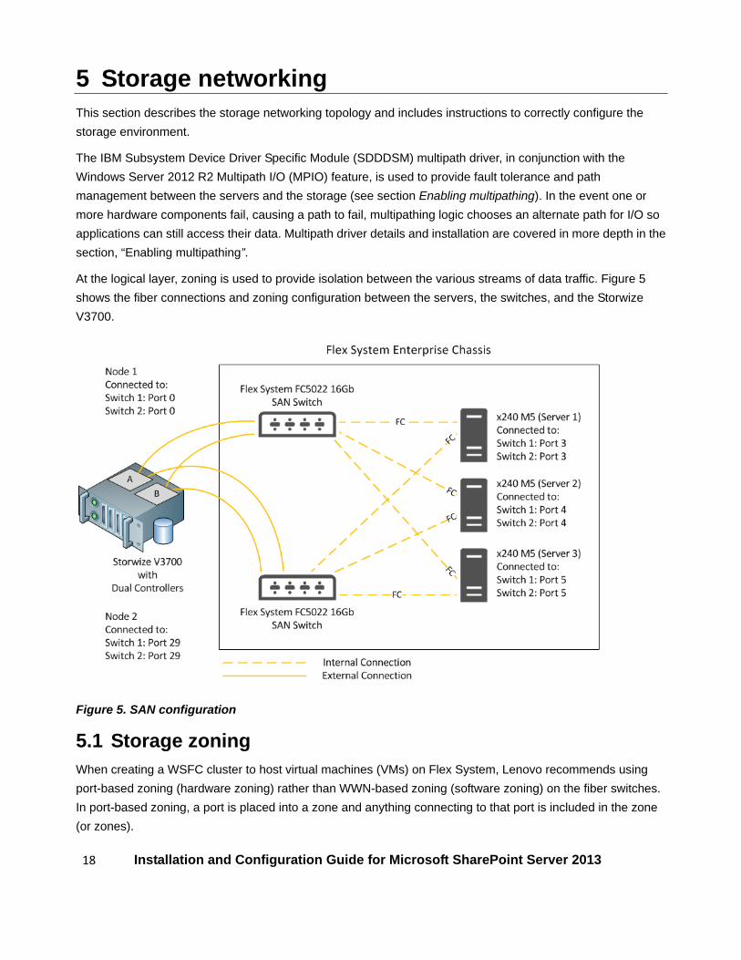
5 Storage networking This section describes the storage networking topology and includes instructions to correctly configure the storage environment.
The IBM Subsystem Device Driver Specific Module (SDDDSM) multipath driver, in conjunction with the Windows Server 2012 R2 Multipath I/O (MPIO) feature, is used to provide fault tolerance and path management between the servers and the storage (see section Enabling multipathing). In the event one or more hardware components fail, causing a path to fail, multipathing logic chooses an alternate path for I/O so applications can still access their data. Multipath driver details and installation are covered in more depth in the section, “Enabling multipathing”.
At the logical layer, zoning is used to provide isolation between the various streams of data traffic. Figure 5 shows the fiber connections and zoning configuration between the servers, the switches, and the Storwize V3700.
Figure 5. SAN configuration
5.1 Storage zoning When creating a WSFC cluster to host virtual machines (VMs) on Flex System, Lenovo recommends using port-based zoning (hardware zoning) rather than WWN-based zoning (software zoning) on the fiber switches. In port-based zoning, a port is placed into a zone and anything connecting to that port is included in the zone (or zones).

19 Installation and Configuration Guide for Microsoft SharePoint Server 2013
Lenovo recommends using single-initiator zoning for path isolation. In single-initiator zoning, zones are created based on a single initiator. This means that each zone contains a single HBA port, or initiator. Multiple storage array ports can be added to the zone without violating the single initiator rule as storage arrays are the targets.
Zoning can be configured from the switch’s command-line interface or from the management web interface. This guide focuses on the command-line interface.
Table 2 lists the port definitions with connected devices, as well as the aliases that are defined on each of the SAN Switches. The WWNs in Table 2 are unique to the test environment; the WWNs for your environment will be different from those shown here.
Table 2. Port definitions on the Flex System FC3171 8Gb SAN Switches
Flex System FC5022 16 SAN Switch 1
Port Connected To Alias Zones
3 HBA Port-1 of Server 1 S1PORT1 ZONE1 4 HBA Port-1 of Server 2 S2PORT1 ZONE2 5 HBA Port-1 of Server 3 S3PORT1 ZONE3 0 V3700 Node-1 Port-1 N1PORT1 ZONE1, ZONE2, ZONE3 29 V3700 Node-2 Port-1 N2PORT1 ZONE1, ZONE2, ZONE3
Flex System FC5022 16 SAN Switch 2
Port Connected To Alias Zones
3 HBA Port-2 of Server 1 S1PORT2 ZONE1 4 HBA Port-2 of Server 2 S2PORT2 ZONE2 5 HBA Port-2 of Server 3 S3PORT2 ZONE3 0 V3700 Node-1 Port-2 N1PORT2 ZONE1, ZONE2, ZONE3 29 V3700 Node-2 Port-2 N2PORT2 ZONE1, ZONE2, ZONE3
To create the necessary zoning, Lenovo recommends following the steps below:
1. Create aliases for the HBA ports and the V3700 ports.
2. Create zones using the aliases created in step 1. Each zone should consist of a single initiator (HBA port), and two V3700 ports, as shown in Table 2 above.
3. Create the zone configuration and add the zones created in step 2.
4. Save the zone configuration.
5. Enable the zone configuration.
To define the zones on the switches, perform the following steps:
1. Using SSH (Secure Shell), log in to the CLI of the first switch using the management IP address of the switch.
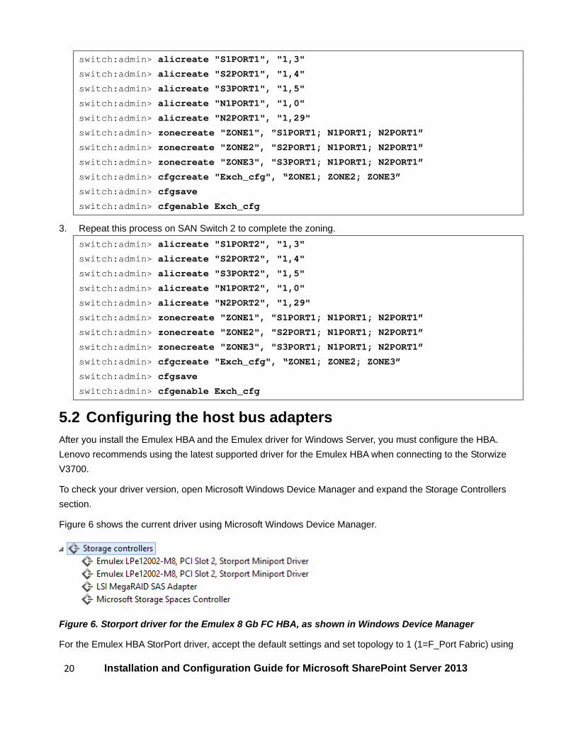
2. Run the following commands on SAN Switch 1 to create the zone configuration.
20 Installation and Configuration Guide for Microsoft SharePoint Server 2013
switch:admin> alicreate "S1PORT1", "1,3"
switch:admin> alicreate "S2PORT1", "1,4"
switch:admin> alicreate "S3PORT1", "1,5"
switch:admin> alicreate "N1PORT1", "1,0"
switch:admin> alicreate "N2PORT1", "1,29"
switch:admin> zonecreate "ZONE1", "S1PORT1; N1PORT1; N2PORT1”
switch:admin> zonecreate "ZONE2", "S2PORT1; N1PORT1; N2PORT1”
switch:admin> zonecreate "ZONE3", "S3PORT1; N1PORT1; N2PORT1”
switch:admin> cfgcreate "Exch_cfg", “ZONE1; ZONE2; ZONE3”
switch:admin> cfgsave
switch:admin> cfgenable Exch_cfg
3. Repeat this process on SAN Switch 2 to complete the zoning. switch:admin> alicreate "S1PORT2", "1,3"
switch:admin> alicreate "S2PORT2", "1,4"
switch:admin> alicreate "S3PORT2", "1,5"
switch:admin> alicreate "N1PORT2", "1,0"
switch:admin> alicreate "N2PORT2", "1,29"
switch:admin> zonecreate "ZONE1", "S1PORT1; N1PORT1; N2PORT1”
switch:admin> zonecreate "ZONE2", "S2PORT1; N1PORT1; N2PORT1”
switch:admin> zonecreate "ZONE3", "S3PORT1; N1PORT1; N2PORT1”
switch:admin> cfgcreate "Exch_cfg", “ZONE1; ZONE2; ZONE3”
switch:admin> cfgsave
switch:admin> cfgenable Exch_cfg
5.2 Configuring the host bus adapters After you install the Emulex HBA and the Emulex driver for Windows Server, you must configure the HBA. Lenovo recommends using the latest supported driver for the Emulex HBA when connecting to the Storwize V3700.
To check your driver version, open Microsoft Windows Device Manager and expand the Storage Controllers section.
Figure 6 shows the current driver using Microsoft Windows Device Manager.
Figure 6. Storport driver for the Emulex 8 Gb FC HBA, as shown in Windows Device Manager
For the Emulex HBA StorPort driver, accept the default settings and set topology to 1 (1=F_Port Fabric) using

21 Installation and Configuration Guide for Microsoft SharePoint Server 2013
the Emulex utility OneCommand Manager (default is 2). Reset the port using OneCommand Manager after making the change (the option to reset the port is located under Port in the main menu).
Figure 7 shows the location of the topology setting in OneCommand Manager.
Figure 7. Changing the topology of the HBA ports using OneCommand Manager
Modify the topology setting to “1” for each of the HBA ports on each of the servers before continuing.
5.3 Enabling multipathing The IBM Subsystem Device Driver Device-Specific Module (SDDDSM) is a multipath driver that is required when multiple connections to storage are present. When you use SDDDSM for multipathing with the Storwize V3700, it is important to use the latest HBA driver provided by IBM.
For this document, we used SDDDSM version 2.4.4.0 for Windows Server 2012 R2.
SDDDSM works in conjunction with the Microsoft Multipath I/O (MPIO) feature to support dynamic multipathing. Dynamic multipathing automatically configures and updates available paths to a storage volume. SDDDSM uses a load-balancing policy to equalize the load across all preferred paths. No user intervention is required, other than the typical new device discovery on a Windows Server operating system. SDDDSM is dependent on
22 Installation and Configuration Guide for Microsoft SharePoint Server 2013
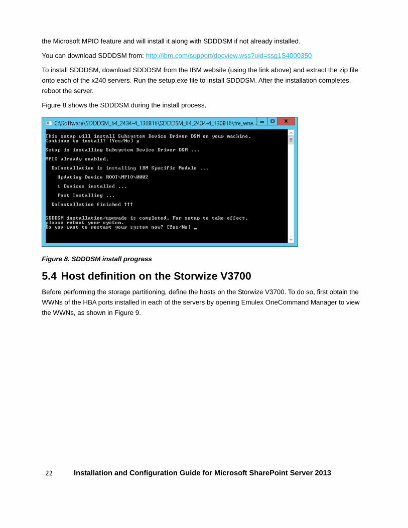
the Microsoft MPIO feature and will install it along with SDDDSM if not already installed.
You can download SDDDSM from: http://ibm.com/support/docview.wss?uid=ssg1S4000350
To install SDDDSM, download SDDDSM from the IBM website (using the link above) and extract the zip file onto each of the x240 servers. Run the setup.exe file to install SDDDSM. After the installation completes, reboot the server.
Figure 8 shows the SDDDSM during the install process.
Figure 8. SDDDSM install progress
5.4 Host definition on the Storwize V3700 Before performing the storage partitioning, define the hosts on the Storwize V3700. To do so, first obtain the WWNs of the HBA ports installed in each of the servers by opening Emulex OneCommand Manager to view the WWNs, as shown in Figure 9.

23 Installation and Configuration Guide for Microsoft SharePoint Server 2013
Figure 9. Finding WWPNs using OneCommand Manager
After you have listed the HBA port WWNs, open the Storwize V3700 web interface and authenticate. The web interface is shown in Figure 10.
Figure 10. Storwize V3700 Web UI
To define the hosts, follow the steps below:
1. Open the Hosts window by clicking the icon illustrated by a disk-group attached to a server (highlighted in Figure 11) and then click Hosts.
24 Installation and Configuration Guide for Microsoft SharePoint Server 2013
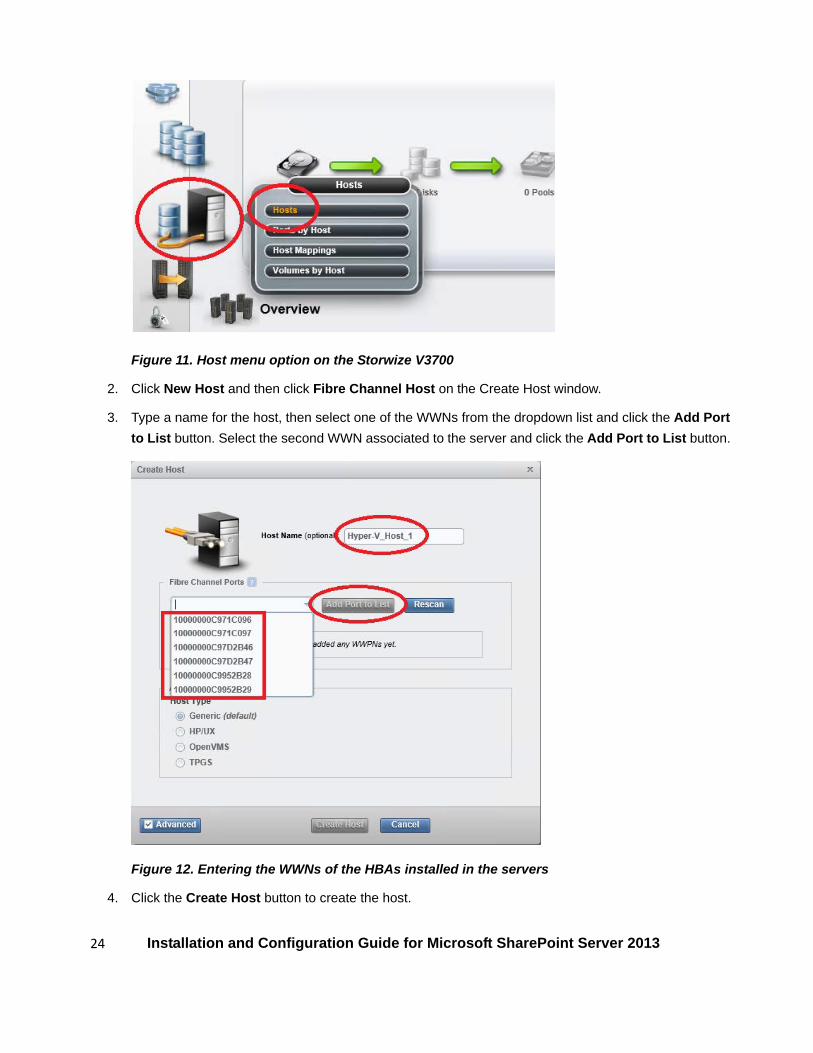
Figure 11. Host menu option on the Storwize V3700
2. Click New Host and then click Fibre Channel Host on the Create Host window.
3. Type a name for the host, then select one of the WWNs from the dropdown list and click the Add Port to List button. Select the second WWN associated to the server and click the Add Port to List button.
Figure 12. Entering the WWNs of the HBAs installed in the servers
4. Click the Create Host button to create the host.

25 Installation and Configuration Guide for Microsoft SharePoint Server 2013
5. Repeat the process for the HBA ports on the remaining servers.

26 Installation and Configuration Guide for Microsoft SharePoint Server 2013
6 Storage partitioning This section provides details on storage partitioning using the Storwize V3700 management interface.
First, a storage pool is created. Then the storage pool is split into two logical drives: a 5 GB logical drive for the cluster quorum drive and a larger drive for the cluster-shared volume (CSV), which houses the Hyper-V VHDX files for the VM system files.
6.1 Create storage pool To create a storage pool, follow the steps below:
1. Open the Internal Storage window by clicking the graphic shown in Figure 13 and then clicking Internal Storage from the pop-up menu.
Figure 13. Internal Storage menu option
2. On the Internal Storage window, click the Configure Storage button to open the Configure Internal Storage dialogue box.
3. On the Configure Internal Storage dialogue box select the radio button labelled Select a different configuration. Next, select the appropriate drive class from the from the Drive Class drop-down (the drive class will vary depending on the type of drives you have installed). In this example, 3 TB large form factor (LFF) 7.2k NL-SAS drives are used for the cluster volumes. Next, select the type of RAID to use for the MDisk; in is this case it is RAID-10 for the cluster pool. Next select optimize for performance. Finally, enter the number of drives you want defined as MDisks. Figure 14 shows that 8 disks have been selected to create the MDisk.

27 Installation and Configuration Guide for Microsoft SharePoint Server 2013
Figure 14. Configuring internal storage
4. Click Next after you have configured the internal storage.
5. On the next page of the dialogue box, select the radio button labelled Create one more new pools. Finally, type a name for the new storage pool and click Finish.
6.2 Create logical volumes The next step is to define logical volumes from the storage pool that you just created and map the volumes to the hosts that were defined in a previous section. To define the logical volumes and map them to the hosts follow the steps below:
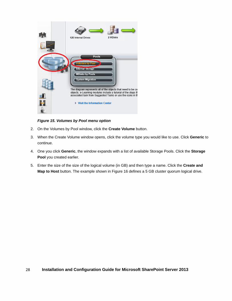
1. Open the Volumes by Pool window by clicking the graphic shown in Figure 15 and then clicking Volumes by Pool.
28 Installation and Configuration Guide for Microsoft SharePoint Server 2013
Figure 15. Volumes by Pool menu option
2. On the Volumes by Pool window, click the Create Volume button.
3. When the Create Volume window opens, click the volume type you would like to use. Click Generic to continue.
4. One you click Generic, the window expands with a list of available Storage Pools. Click the Storage Pool you created earlier.
5. Enter the size of the size of the logical volume (in GB) and then type a name. Click the Create and Map to Host button. The example shown in Figure 16 defines a 5 GB cluster quorum logical drive.

29 Installation and Configuration Guide for Microsoft SharePoint Server 2013
Figure 16. Defining the size and name of a logical volume
6. After the task completes, click the Continue button.
7. On the next window, select a host from the drop-down to open the Modify Host Mappings window.
8. Click the Apply button to apply the current mapping, then using the Host drop-down select the second server, as shown in Figure 17.

30 Installation and Configuration Guide for Microsoft SharePoint Server 2013
Figure 17. Modify Host Mappings window
9. Click the Apply button again, to apply the same mapping to the second host. At this point, a warning dialogue will appear informing you a logical volume has been mapped to multiple hosts. Click Map All Volumes to continue.
10. Repeat steps 8 and 9 to map the quorum volume to the third server.
Next, follow the steps outlined above to create a volume to house the VHDX files for the VMs. This guide uses 4 VMs per data center. Each VM will be assigned a 127 GB VHDx file for the VM’s system files. Therefore, a 508 GB volume is required to house the VHDx files. However, extra space should be allowed for additional VMs that might be needed in the future. Therefore, create a single volume using the storage pool’s remaining capacity and map it to the three servers that comprise the Hyper-V cluster.
Microsoft recommends the following minimum free space on CSV volumes containing Hyper-V VM VHD and/or VHDX files:
• 15% free space if the partition size is less than 1 TB • 10% free space if the partition size is between 1 TB and 5 TB • 5% free space if the partition size is greater than 5 TB

31 Installation and Configuration Guide for Microsoft SharePoint Server 2013
7 Creating a Windows cluster This section describes how to configure the Windows servers for clustering and connect them to the shared storage volumes used for the cluster shared volume (CSV) and for the cluster quorum.
The logical volumes created in the previous section should now be visible to the servers. Before continuing, verify that the logical volumes are visible in the Disks section of Windows Disk Manager on all the servers, as shown in Figure 18. It may be necessary to perform a disk rescan to refresh the list.
Figure 18. Windows Disk Manager showing the new logical volumes on a Hyper-V cluster server
At this stage, only one server can have a disk online at a time, until they have been added to CSV using the Failover Cluster Manager.
Verify that the drives can be brought online from a single server. Once the drives are online, initialize the drives as GPT (GUID Partition Table) disks and then create a new Windows volume on each of the drive using the entire available capacity. It is not necessary to assign drive letters because the volumes will be used for specific clustering roles such as CSV and cluster quorum. Format the new volumes using NTFS. Volumes used for VHD/VHDx files, including CSV’s, should use an allocation size of 64K.
7.1 Create the WSFC cluster To create the WSFC cluster on Windows Server follow the steps outlined below:
1. If the Failover Clustering feature has not been installed on the servers, install the feature using Windows Server Manager.
2. After the Failover Clustering feature is installed, open the Failover Cluster Manager.
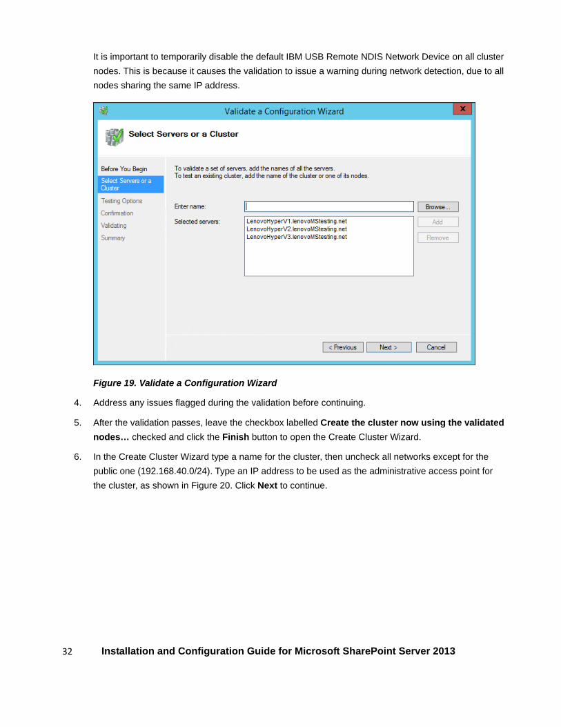
3. Validate the server configuration by running the Validate a Configuration Wizard from the Failover Cluster Manager. Because the cluster has not yet been formed, add the servers to the validation, as shown in Figure 19. The cluster validation wizard checks for available cluster-compatible servers, and validates storage and networking. To ensure a successful test, verify that the intended cluster storage is online to only one of the cluster nodes.
32 Installation and Configuration Guide for Microsoft SharePoint Server 2013
It is important to temporarily disable the default IBM USB Remote NDIS Network Device on all cluster nodes. This is because it causes the validation to issue a warning during network detection, due to all nodes sharing the same IP address.
Figure 19. Validate a Configuration Wizard
4. Address any issues flagged during the validation before continuing.
5. After the validation passes, leave the checkbox labelled Create the cluster now using the validated nodes… checked and click the Finish button to open the Create Cluster Wizard.
6. In the Create Cluster Wizard type a name for the cluster, then uncheck all networks except for the public one (192.168.40.0/24). Type an IP address to be used as the administrative access point for the cluster, as shown in Figure 20. Click Next to continue.

33 Installation and Configuration Guide for Microsoft SharePoint Server 2013
Figure 20. Defining the administrative access point for the cluster
7. On the Confirmation page, uncheck the checkbox labelled Add all eligible storage to the cluster and click Next.
8. After the cluster has formed, click the Finish button to exit the wizard and return to the Failover Cluster Manager.
7.2 Adding the cluster shared volumes After the cluster has been created, the storage volumes need to be assigned as disks under Windows. Follow the steps below to assign the disks.
1. Using Failover Cluster Manager, select the cluster from the navigation pane and expand the Storage section. Click Add Disk in the Actions pane, as shown in Figure 21.

34 Installation and Configuration Guide for Microsoft SharePoint Server 2013
Figure 21. Adding a disk to the cluster
2. Confirm that both the cluster quorum volume and the VHDx volume are checked and then click OK to continue.
3. Lenovo recommends renaming the disks within the Failover Cluster Manager for better documentation. After the disks have been added, you can right-click a disk and click Properties. Type a new name for the disk and click the OK button. The names used in this guide are Quorum and CSV_VHDx.
4. Right-click the disk named CSV_VHDx (the 11.00 TB disk), and click Add to Cluster Shared Volumes from the right-click menu. The Assigned To column will update from Assigned Storage to Cluster Shared Volume.
Next the quorum disk needs to be assigned. To manually assign the quorum disk, follow the steps below:
1. With the cluster selected, on the Actions pane click More Actions (shown in Figure 22), and then click Configure Cluster Quorum Settings. The Configure Cluster Quorum Wizard appears. Click Next.
Figure 22. Failover Cluster Manager - More Actions menu option
2. On the Select Quorum Configuration Options page, select the radio button labelled Select the

35 Installation and Configuration Guide for Microsoft SharePoint Server 2013
quorum witness. Click Next.
3. On the Select Quorum Witness page, select the radio button labelled Configure a disk witness. Click Next.
4. On the Configure Storage Witness page, check the drive you would like to use for the cluster quorum, as shown in Figure 23. Click Next.
Figure 23. Select a disk to use as the quorum
5. Click Next on the Confirmation page. Once it completes click Finish to close the wizard.
6. Verify that the disk has successfully been added as a cluster quorum disk witness by navigating to Disks and checking the Assigned To column. The cluster quorum disk should be assigned to Disk Witness in Quorum.
Once you have assigned the cluster shared volume and the cluster quorum disk, the storage section should look similar to that shown in Figure 24.

36 Installation and Configuration Guide for Microsoft SharePoint Server 2013
Figure 24. The Storage section of Failover Cluster Manager
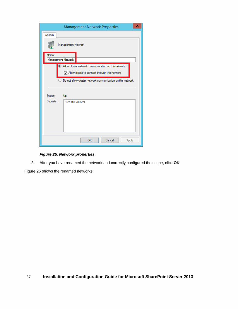
7.3 Configuring the cluster network Lenovo recommends renaming the cluster networks for better documentation. The networks should also be configured to limit the scope of network traffic to its intended use. To change the name and scope of the network follow the steps below:
1. Expand the Networks section in the Navigation pane and right-click each of the listed networks. Click Properties from the right-click menu.
2. Rename the network using Table 1 (from page 8) to determine the name and scope of the network. The Live Migration network and the Cluster Private network should be Cluster Only. The Management network and the Public network should include the clients. If a network requires client access, check the box labeled Allow clients to connect through this network, as shown in Figure 25.
37 Installation and Configuration Guide for Microsoft SharePoint Server 2013
Figure 25. Network properties
3. After you have renamed the network and correctly configured the scope, click OK.
Figure 26 shows the renamed networks.

38 Installation and Configuration Guide for Microsoft SharePoint Server 2013
Figure 26. Renamed networks on the Hyper-V cluster
The last step is to configure Live Migration:
1. Click Live Migration Settings in the Actions pane to open the Live Migration Settings window.
2. Uncheck all networks except the 192.168.50.0 network (named Live Migration Network). Click OK.

39 Installation and Configuration Guide for Microsoft SharePoint Server 2013
8 Microsoft Hyper-V configuration This section covers the Hyper-V configuration for the Hyper-V cluster servers.
Using Hyper-V Manager, set the default paths for VM creation to use the CSV. The CSV disks are identified by a path name and each path appears to be on the system drive of the host server as a numbered volume under the \ClusterStorage folder. This path is the same when viewed from any node in the cluster. For example, the CSV created earlier will appear to each node in the cluster as C:\ClusterStorage\Volume1.
To configure Hyper-V to use the CSV follow the steps outlined below:
1. Using Hyper-V Manager, select the Hyper-V server and click Hyper-V Settings… from the Actions pane.
2. In the Server section, select the first option, Virtual Hard Disks. Type a new path for the VHDX files that points to the CSV.
3. Repeat the process to change the path for the VM configuration settings by selecting VMs and typing a new path that points to the CSV.
4. Repeat this process on the remaining cluster nodes.
At this point the Hyper-V cluster is operational and ready to host active roles.

40 Installation and Configuration Guide for Microsoft SharePoint Server 2013
9 Creating a highly available VM for Exchange After the Hyper-V cluster is up and running, the Exchange virtual infrastructure can be created. The first step is to build the VMs that will provide the virtual infrastructure for the Exchange environment.
For this guide, four VMs are required in each data center. The VMs have the following configuration:
• 160 GB memory • 13 virtual processors • 1 SCSI controller with two VHDX files
o 127 GB VHDX for the system files and operating system o 80 GB VHDX for the Exchange installation
• 2 network adapters o Network adapter 1 = Public network 192.168.40.x o Network adapter 2 = Exchange database replication network 192.168.30.x
9.1 Creation of Exchange VMs Follow the steps below to create the highly available VMs:
1. In Failover Cluster Manager, with the cluster selected, click Roles in the Navigation pane.
2. In the Actions pane, click Virtual Machines…, and then click New Virtual Machine. The New Virtual Machine Wizard appears. Select one of the cluster nodes and click OK.
It is important to spread the VMs among the cluster nodes. Don’t place all the VMs on the same node.
3. Click Next to bypass the Before You Begin page.
4. On the Specify Name and Location page, type a name for the VM. Verify that the location to store the VM files is the path to the cluster shared volume. Click Next.
5. On the Specify Generation page, select Generation 2. Click Next.
6. On the Assign Memory page, specify the amount of memory required for the operating system that will run on this VM. Click Next.
Do not select dynamic memory as it is not supported by Exchange Server 2013.
7. On the Configure Networking page, connect the network adapter to the virtual switch that is associated with the physical network adapter (ClusterSwitch in this guide). Click Next.
8. On the Connect Virtual Hard Disk page, select Create a virtual hard disk. If you want to change the name, type a new a name for the virtual hard disk. The default location of the VM files is located on the CSV and was configured in section Microsoft Hyper-V configuration. Click Next.
9. On the Installation Options page, click Install an operating system from a bootable image file. Navigate to the location of your installation media and select the appropriate file. Click Open to select the file, and then click Finish.

41 Installation and Configuration Guide for Microsoft SharePoint Server 2013
10. After the Windows installation completes, install Windows updates and the Exchange Server 2013 prerequisites as described here: http://social.technet.microsoft.com/wiki/contents/articles/16730.installing-microsoft-exchange-server-2013-prerequisites-on-windows-server-2012.aspx
After the VM is created, the High Availability Wizard in Failover Cluster Manager automatically configures the VM for high availability.
Before the VM is powered on, assign the correct number of virtual processors using the following steps:
1. In Failover Cluster Manager, select the cluster and click Roles in the Navigation pane.
2. In the Details pane, right-click the VM that was just created and click Settings.
3. Under the Hardware section of the Settings window, click Processor.
In the Details pane of the Settings window, use the drop-down labelled Number of virtual processors to assign the correct number of processors.
4. Click OK.
The VM configuration is now complete. Repeat the configuration process on the remaining VMs.
9.2 Changing the VM save state on shutdown for migration For each VM you can configure automatic stop and start behavior if a physical computer shuts down. The options for stop are as follows:
• Save State. The current state of the VM is saved. When the VM is started, Hyper-V restores the VM to the saved state.
• Turn Off. This is the equivalent of pulling the power plug on a server. • Shut Down the Guest OS. This is the equivalent of shutting down a computer by using the Windows
Shut down option.
VMs that start from a saved state will be out of sync with the other servers. Therefore, Microsoft recommends that you configure the Exchange VMs to use shutdown as the migration method (rather than save state), because it minimizes that chances that the VM can be corrupted. When a shutdown happens, all timer jobs that are running can finish, and there will be no synchronization issues when the VM restarts.
Therefore, all failover activity occurring at the hypervisor level must result in a cold boot when the VM is activated on the target node. All planned migrations must result in either a shutdown and cold boot, or an online migration that makes use of a technology such as Hyper-V Live Migration.
The opposite of an automatic stop is an automatic start. Hyper-V provides the following startup options when the physical server restarts:
• Do nothing. You have to start the VM manually regardless of its state when the physical server shut down.
• Automatically start if the VM was running when the service stopped.

42 Installation and Configuration Guide for Microsoft SharePoint Server 2013
• Always start this VM automatically. Hyper-V starts the VM regardless of its state when the physical server shut down.
Microsoft recommends you select either of the first two options. Both options are acceptable. In addition to the previous start options, you can configure a startup time delay for a VM. Microsoft recommends you do this to reduce resource contention on a virtualization host. However, if your start option is to do nothing, this is not an issue.
To configure the VMs to shut down rather than save state upon a migration, follow the steps below:
1. In Failover Cluster Manager, select the cluster and click Roles in the Navigation pane.
2. In the Details pane, right-click the VM that was just created in the section Creation of Exchange VMs. Click Settings.
3. In the Navigation pane, scroll down to the Management section. Click Automatic Stop Action.
4. In the Details pane, select the radio button to shut down the guest operating system. Click OK.
To configure the VMs to automatically start, follow the steps below:
1. In Failover Cluster Manager, select the cluster and click Roles in the Navigation pane.
2. In the Details pane, right-click the VM that was just created and click Settings.
3. In the Navigation pane, scroll down to the Management section. Click Automatic Start Action.
4. In the Details pane, select the radio button to automatically start if it was running when the service stopped.
5. Under the section labeled Automatic Start Delay enter the startup delay in seconds to stagger the start of the VMs. (For example the first VM might have a 0 second start delay, while the second VM has a 20 second start delay.) Click OK.
9.3 VM preferred owners To help prevent situations where all VMs migrate to a single cluster node when others are available, you can configure a highly available VM with degrees of affinity for available nodes in the cluster. This affinity is called preferred owners. For example, a VM that is hosted on node-1 of the cluster and has preferred owners configured as node-1, node 2, and node-3 in descending priority order would failover to node-2 if node-1 were to fail. If node-2 failed, or was offline, the VM would failover to node-3.
The VMs are configured as shown below in Table 3.

43 Installation and Configuration Guide for Microsoft SharePoint Server 2013
Table 3. VM cluster node preferred ownership
VMs Hyper-V Cluster Node1 Hyper-V Cluster Node 2 Hyper-V Cluster Node 3
Exchange VM 1 1st Priority 2nd Priority 3rd Priority
Exchange VM 2 3rd Priority 1st Priority 2nd Priority
Exchange VM 3 2nd Priority 3rd Priority 1st Priority
Exchange VM 4 1st Priority 2nd Priority 3rd Priority
To configure preferred ownership follow the steps below:
1. In Failover Cluster Manager, select the cluster and click Roles in the Navigation pane.
2. In the Details pane, double-click the VM you wish to configure to open its Properties window.
3. In the Properties window, click the checkbox next to the Hyper-V host servers and use the arrow keys to change the priority with the highest priority on top, as shown in Figure 27. Click OK.
Figure 27. Changing host server preferred ownership

44 Installation and Configuration Guide for Microsoft SharePoint Server 2013
4. Repeat this process to configure the preferred owner of the remaining virtual machines.
9.4 VM network configuration The VMs are each assigned two virtual network adapters. The first network adapter is on the public network (VLAN 40) so the VM can join the domain. The second network adapter is on the Exchange database replication network (VLAN 30) so the Exchange mailbox databases have an isolated network to use for replication.
To add and assign the VM’s network adapters, follow the steps below:
1. After a VM has been created, from within Failover Cluster Manager, click Roles from the navigation pane.
2. Right-click the VM and click Settings.
3. Click Add Hardware from the Hardware section.
If you added a virtual switch during the creation of the VM, there will be an existing network adapter under the Hardware section. Therefore, only one additional adapter should be created. The existing adapter will need a VLAN assigned.
4. Select Network Adapter from the Hardware section and click Add, as shown in Figure 28.
Figure 28. Adding a virtual network adapter
5. On the next page, select ClusterSwitch (or the name you defined for the virtual switch) from the drop-down labelled Virtual switch. Check the checkbox labelled Enable virtual LAN identification and type 40 as the VLAN identifier (or 30, if you are creating the adapter for the database replication network). Click OK.
6. Repeat this process until each VM has two network adapters: one on VLAN 40 and one on VLAN 30.
After the network adapters have been added and assigned to VLANs, start the VMs and assign IP addresses from within Windows Server and join the VMs to the domain.
45 Installation and Configuration Guide for Microsoft SharePoint Server 2013
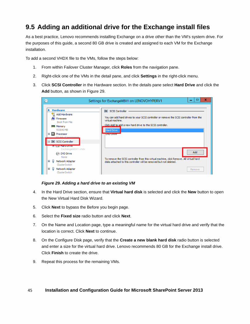
9.5 Adding an additional drive for the Exchange install files As a best practice, Lenovo recommends installing Exchange on a drive other than the VM’s system drive. For the purposes of this guide, a second 80 GB drive is created and assigned to each VM for the Exchange installation.
To add a second VHDX file to the VMs, follow the steps below:
1. From within Failover Cluster Manager, click Roles from the navigation pane.
2. Right-click one of the VMs in the detail pane, and click Settings in the right-click menu.
3. Click SCSI Controller in the Hardware section. In the details pane select Hard Drive and click the Add button, as shown in Figure 29.
Figure 29. Adding a hard drive to an existing VM
4. In the Hard Drive section, ensure that Virtual hard disk is selected and click the New button to open the New Virtual Hard Disk Wizard.
5. Click Next to bypass the Before you begin page.
6. Select the Fixed size radio button and click Next.
7. On the Name and Location page, type a meaningful name for the virtual hard drive and verify that the location is correct. Click Next to continue.
8. On the Configure Disk page, verify that the Create a new blank hard disk radio button is selected and enter a size for the virtual hard drive. Lenovo recommends 80 GB for the Exchange install drive. Click Finish to create the drive.
9. Repeat this process for the remaining VMs.

46 Installation and Configuration Guide for Microsoft SharePoint Server 2013
10 Installing and configuring Exchange This section covers the steps required to install and configure Exchange Server 2013.
Once Windows Server 2012 has been installed on the VMs and they have been joined to the domain and fully updated, a number of prerequisite software must be installed.
10.1 Active Directory requirements The minimum requirement for Active Directory is that the forest functionality mode must be at Windows Server 2003 or higher. The following article describes how to raise the forest functional level:
http://technet.microsoft.com/en-us/library/cc730985.aspx
10.2 Installing software prerequisites Exchange Server 2013 has two roles, the Mailbox role and the Client Access Server (CAS) role. These roles can be deployed separately on different VMs or combined onto a single VM in what is called a multi-role assignment. Microsoft recommends deploying Exchange Server 2013 in a multi-role assignment.
To install the Exchange prerequisites follow the steps below:
1. Run Windows PowerShell as Administrator and run the following command: Install-WindowsFeature AS-HTTP-Activation, Desktop-Experience,
NET-Framework-45-Features, RPC-over-HTTP-proxy, RSAT-Clustering,
RSAT-Clustering-CmdInterface, RSAT-Clustering-Mgmt,
RSAT-Clustering-PowerShell, Web-Mgmt-Console, WAS-Process-Model,
Web-Asp-Net45, Web-Basic-Auth, Web-Client-Auth, Web-Digest-Auth,
Web-Dir-Browsing, Web-Dyn-Compression, Web-Http-Errors, Web-Http-Logging,
Web-Http-Redirect, Web-Http-Tracing, Web-ISAPI-Ext, Web-ISAPI-Filter,
Web-Lgcy-Mgmt-Console, Web-Metabase, Web-Mgmt-Console, Web-Mgmt-Service,
Web-Net-Ext45, Web-Request-Monitor, Web-Server, Web-Stat-Compression,
Web-Static-Content, Web-Windows-Auth, Web-WMI, Windows-Identity-Foundation,
RSAT-ADDS
2. Once the PowerShell command finishes as shown in Figure 30, reboot the VM.
Figure 30. Installing Exchange prerequisites

47 Installation and Configuration Guide for Microsoft SharePoint Server 2013
3. Next, download and install the Microsoft Unified Communications Managed API 4.0, Core Runtime 64-bit. The download can be obtained at the following website: http://microsoft.com/en-us/download/details.aspx?id=34992
4. Then, download and Install Microsoft Office 2010 Filter Packs 64-bit. The download can be obtained at the following website: http://microsoft.com/en-us/download/details.aspx?id=17062
5. Finally, once the filter pack has been installed, download and install SP1 for the filter pack. Service Pack 1 for Microsoft Office Filter Pack 2010 64-bit Edition can be downloaded from the following website: http://microsoft.com/en-us/download/details.aspx?id=26604
Once the prerequisite software has been installed, Exchange server 2013 can be installed on the VM.
10.3 Installing Exchange Once the prerequisites have been installed, install Exchange on the VMs.
1. On the Exchange installation splash screen select the appropriate radio button (see Figure 31) depending on whether you want the installation to check for Windows Updates or not and then click Next.
Figure 31. Exchange Installation Check for Updates page
2. On the Windows Update page, click Next to continue.
48 Installation and Configuration Guide for Microsoft SharePoint Server 2013
3. Click Next to bypass the Introduction page.
4. Accept the License Agreement and click Next.
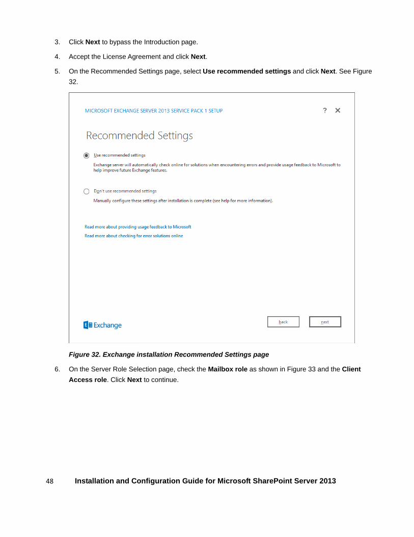
5. On the Recommended Settings page, select Use recommended settings and click Next. See Figure 32.
Figure 32. Exchange installation Recommended Settings page
6. On the Server Role Selection page, check the Mailbox role as shown in Figure 33 and the Client Access role. Click Next to continue.

49 Installation and Configuration Guide for Microsoft SharePoint Server 2013
Figure 33. Exchange installation Server Role Selection page
6. On the Installation Space and Location page, browse to a location (see Figure 34) to install Exchange and click Next.

50 Installation and Configuration Guide for Microsoft SharePoint Server 2013
Figure 34. Exchange installation Installation Space and Location page
7. On the Exchange Organization page type a name for your organization as shown in Figure 35 and click Next.

51 Installation and Configuration Guide for Microsoft SharePoint Server 2013
Figure 35. Exchange installation Exchange Organization page
8. On the Malware Protection Settings page determine whether you want to disable malware scanning by selecting the appropriate radio button. Click Next to initiate readiness checks.
9. After the readiness check completes, address any issues and click Install.
10. Once the installation completes, click Finish.
10.4 Exchange 2013 post-installation configuration tasks For a list of common post-installation configuration tasks review the following TechNet article:
http://technet.microsoft.com/en-us/library/bb124397(v=exchg.150).aspx

52 Installation and Configuration Guide for Microsoft SharePoint Server 2013
References • Reference Architecture: Microsoft Exchange Server 2013
http://lenovopress.com/tips1308
• Exchange 2013 post-installation tasks http://technet.microsoft.com/en-us/library/bb124397(v=exchg.150).aspx
• Checklist: Perform a new installation of Exchange 2013 http://technet.microsoft.com/en-us/library/ff805042(v=exchg.150).aspx
• Create a Windows Server Failover Clustering cluster http://technet.microsoft.com/en-us/library/Dn505754.aspx
• Configure a Hyper-V virtual machine for high availability http://technet.microsoft.com/en-us/library/Dd759216.aspx

53 Installation and Configuration Guide for Microsoft SharePoint Server 2013
Trademarks and special notices
© Copyright Lenovo 2016.
References in this document to Lenovo products or services do not imply that Lenovo intends to make them available in every country.
Lenovo, the Lenovo logo and Flex System, are trademarks of Lenovo.
IBM, the IBM logo, and ibm.com are trademarks or registered trademarks of International Business Machines Corporation in the United States, other countries, or both.
Microsoft, Windows, Windows Server, the Windows logo and Hyper-V are trademarks of Microsoft Corporation in the United States, other countries, or both.
Intel, Intel Inside (logos), and Xeon are trademarks of Intel Corporation in the United States, other countries, or both.
Other company, product, or service names may be trademarks or service marks of others.
Information is provided "AS IS" without warranty of any kind.
All customer examples described are presented as illustrations of how those customers have used Lenovo products and the results they may have achieved. Actual environmental costs and performance characteristics may vary by customer.
Information concerning non-Lenovo products was obtained from a supplier of these products, published announcement material, or other publicly available sources and does not constitute an endorsement of such products by Lenovo. Sources for non-Lenovo list prices and performance numbers are taken from publicly available information, including vendor announcements and vendor worldwide homepages. Lenovo has not tested these products and cannot confirm the accuracy of performance, capability, or any other claims related to non-Lenovo products. Questions on the capability of non-Lenovo products should be addressed to the supplier of those products.
All statements regarding Lenovo future direction and intent are subject to change or withdrawal without notice, and represent goals and objectives only. Contact your local Lenovo office or Lenovo authorized reseller for the full text of the specific Statement of Direction.
Some information addresses anticipated future capabilities. Such information is not intended as a definitive statement of a commitment to specific levels of performance, function or delivery schedules with respect to any future products. Such commitments are only made in Lenovo product announcements. The information is presented here to communicate Lenovo’s current investment and development activities as a good faith effort to help with our customers' future planning.
Performance is based on measurements and projections using standard Lenovo benchmarks in a controlled environment. The actual throughput or performance that any user will experience will vary depending upon considerations such as the amount of multiprogramming in the user's job stream, the I/O configuration, the storage configuration, and the workload processed. Therefore, no assurance can be given that an individual user will achieve throughput or performance improvements equivalent to the ratios stated here.
Photographs shown are of engineering prototypes. Changes may be incorporated in production models.
Any references in this information to non-Lenovo websites are provided for convenience only and do not in any manner serve as an endorsement of those websites. The materials at those websites are not part of the materials for this Lenovo product and use of those websites is at your own risk.