Embed Size (px)
Citation preview

September 2020 © 2020 Honeywell. All rights reserved. Document: 800-25695 V1 I
PRO4200
Intelligent Controller (PRO42IC)
Installation and Configuration Guide

September 2020 © 2020 Honeywell. All rights reserved. Document: 800-25695 V1 II
Copyright © 2020 Honeywell. All rights reserved.
All product and brand names are the service marks, trademarks, registered trademarks, or registered service marks of their respective owners. Printed in the United States of America. Honeywell reserves the right to change any information in this document at any time without prior notice.WIN-PAK® is a trademark of Honeywell, Inc.
Ordering Information
Please contact your local Honeywell representative or visit us on the web at www.honeywellaccess.com for information about ordering.
Feedback
Honeywell appreciates your comments about this manual. Please visit us on the web at www.honeywellac-cess.com to post your comments.
Discover | Customer PortalSelf-Service Product Support and Learning Management Systemhttps://honeywelldiscovertraining.com/login/discover/default.asp
YouTube | Honeywell Help and Supporthttps://www.youtube.com/channel/UCBEL6ouNV_LN5lEpYRujMTg/featured

PRO4200 (PRO42IC) Installation and Configuration Guide, Document 800-25695V1 III
1 Notices .......................................................................................................................... . . . . . . . . . 81.1 Warnings and Cautions ............................................................................... . . . . . . . . . . 81.2 Damage During Shipment ........................................................................... . . . . . . . . . 101.3 Electro Static Discharge............................................................................... . . . . . . . . . 101.4 Disclaimer – Product Liability; Mutual Indemnification ....................... . . . . . . . . . 101.5 CE and WEEE Marking............................................................................... . . . . . . . . . 111.6 Unpacking Procedure .................................................................................. . . . . . . . . . 111.7 Shipping Instructions ................................................................................... . . . . . . . . . 111.8 Limited Warranty ......................................................................................... . . . . . . . . . 121.9 Confidentiality .............................................................................................. . . . . . . . . . 121.10 Compliance .................................................................................................. . . . . . . . . . 13
2 Product Overview..................................................................................................... . . . . . . . . 142.1 PRO4200 and PRO3200 .............................................................................. . . . . . . . . . 142.2 Port Settings ................................................................................................... . . . . . . . . . 142.3 Other................................................................................................................ . . . . . . . . . 14
3 Setting Up the PRO4200 Hardware................................................................... . . . . . . . . 173.1 Setting the Jumpers ....................................................................................... . . . . . . . . . 173.2 Setting the DIP Switches ............................................................................. . . . . . . . . . 183.3 Factory Default Communication Parameters: Interface 1 (NIC1)......... . . . . . . . . . 193.4 Bulk Erase Configuration Memory ............................................................ . . . . . . . . . 193.5 Bulk Erase ...................................................................................................... . . . . . . . . . 193.6 Status LEDs .................................................................................................. . . . . . . . . . 213.7 Initialization ................................................................................................... . . . . . . . . . 213.8 LED Activity when Supplying Power to the PRO4200 Interface ......... . . . . . . . . . 213.9 Supplying Power to the PRO4200 Interface ............................................. . . . . . . . . . 223.10 Communications Wiring............................................................................ . . . . . . . . . 233.11 Cabinet Tamper and Power Failure Input Wiring.................................. . . . . . . . . . 243.12 Memory and Real Time Clock Backup Battery ..................................... . . . . . . . . . 24
4 System Configuration via Web Interface ....................................................... . . . . . . . . 254.1 Connecting to ACDSM for the First Time................................................ . . . . . . . . . 254.2 Login Page ..................................................................................................... . . . . . . . . . 254.3 Home Page ..................................................................................................... . . . . . . . . . 264.4 WIN-PAK Network Settings....................................................................... . . . . . . . . . 274.5 Host Communication.................................................................................... . . . . . . . . . 284.6 Device Information ....................................................................................... . . . . . . . . . 304.7 User Configuration........................................................................................ . . . . . . . . . 324.8 Restore Default Screen................................................................................. . . . . . . . . . 334.9 Apply Setting Screen.................................................................................... . . . . . . . . . 344.10 Log Out......................................................................................................... . . . . . . . . . 34
5 Reader Module........................................................................................................... . . . . . . . . 355.1 Reader Wiring................................................................................................ . . . . . . . . . 365.2 Input Wiring................................................................................................... . . . . . . . . . 375.3 Control Output Wiring ................................................................................. . . . . . . . . . 37
TABLE OF CONTENTS

IV www.honeywell.com
(This page is Intentionally left blank)

PRO4200 (PRO42IC) Installation and Configuration Guide, Document 800-25695V1 V
LIST OF FIGURES
Figure 1: PRO4200 Connections, LEDs, and DIP Switches . . . . . . . . . . . . . . . . . 16 Figure 2: PRO4200 Power Terminals . . . . . . . . . . . . . . . . . . . . . . . . . . . . . . . . . . 23 Figure 3: PRO4200 Port Wiring . . . . . . . . . . . . . . . . . . . . . . . . . . . . . . . . . . . . . . 24 Figure 4: PRO4200 TMP and FLT Terminals . . . . . . . . . . . . . . . . . . . . . . . . . . . 24 Figure 5: PRO4200 Web Server Login Screen . . . . . . . . . . . . . . . . . . . . . . . . . . . 25 Figure 6: PRO4200 Web Server Home Page . . . . . . . . . . . . . . . . . . . . . . . . . . . . 26 Figure 7: PRO4200 Web Server Network Settings Screen . . . . . . . . . . . . . . . . . . 27 Figure 8: PRO4200 Host Port Configuration Screen with IP Server Connection . 28 Figure 9: PRO4200 Host Comm Configuration Screen with IP Client Connection 30 Figure 10: PRO4200 Web Server Device HW Info Screen . . . . . . . . . . . . . . . . . 31 Figure 11: PRO4200 Web Server User Info Screen . . . . . . . . . . . . . . . . . . . . . . . 32 Figure 12: PRO4200 Web Server Restore Default Screen . . . . . . . . . . . . . . . . . . 33 Figure 13: PRO4200 Web Server Apply Setting Screen . . . . . . . . . . . . . . . . . . . 34 Figure 14: PRO4200 Intelligent Controller Module Wiring: Connectors TB1,TB3-9. . . . . . . . . . . . . . . . . . . . . . . . . . . . . . . . . . . . 35 Figure 15: PRO4200 Input wiring . . . . . . . . . . . . . . . . . . . . . . . . . . . . . . . . . . . . . 37 Figure 16: PRO4200 Output Wiring . . . . . . . . . . . . . . . . . . . . . . . . . . . . . . . . . . . 38

PRO4200 (PRO42IC) Installation and Configuration Guide, Document 800-25695V1 VI
LIST OF TABLES
Table 1 PRO4200 Jumper Settings ........................................................................................... 17 Table 2 PRO4200 DIP Switch Settings .....................................................................................18 Table 3 PRO4200 Technical Specifications .............................................................................. 20 Table 4 PRO4200 Status LED Combinations During Run Time .............................................. 21 Table 5 Settings for Wiring to a Reader Port ............................................................................36 Table 6 Settings for Configuring an LED Control Terminal ....................................................36

PRO4200 Installation and Configuration Guide, Document 800-25695V1 7
PRO4200 Installation
In this chapter...
Notices 8Product Overview 14Setting Up the PRO4200 Hardware 17System Configuration via Web Interface 25
8
PRO4200 InstallationNotices
www.honeywell.com
1 Notices
1.1 Warnings and Cautions Note: See the Remote Enclosure Installation Manuals PRO32ENC1, PRO32ENC2, PRO32ENC3 or PRO32ENC5 for installation instructions.
Before Installation
Warning: Before installation, TURN OFF the external circuit breaker which supplies power to the system.
Before connecting the device to the power supply, verify that the output voltage is within specifications of the power supply (see 'Technical Specification' on page 20).
Do not apply power to the system until after the installation has been completed. Personal injury or death can occur, and the equipment can be damaged beyond repair, if this precaution is not observed.
Fire Safety and Liability Notice
Warning: Never connect card readers to any critical entry, exit door, barrier, elevator or gate without providing an alternative exit in accordance with all the fire and life safety codes pertinent to the installation.
These fire and safety codes vary from city to city and you must get approval from local fire officials whenever using an electronic product to control a door or other barrier. Use of egress buttons, for example, may be illegal in some cities. In most applications, single action exit without prior knowledge of what to do is a life safety requirement. Always make certain that any required approvals are obtained in writing. DO NOT ACCEPT VERBAL APPROVALS SINCE THEY ARE NOT VALID.
Honeywell never recommends using the PRO4200 or related products for use as a primary warning or monitoring system. Primary warning or monitoring systems should always meet the local fire and safety code requirements. The installer must also test the system on a regular basis by instructing the end user in appropriate daily testing procedures. Failure to test a system regularly could make the installer liable for damages to the end user if a problem occurs.
Earth Grounding
Warning: EARTH ground all enclosures for proper installation.
Use Suppressors
Warning: Use suppressors on all door strikes. Use S-4 suppressors for installation. Honeywell recommends only DC strikes.
PRO4200 InstallationNotices
PRO4200 Installation and Configuration Guide, Document 800-25695V1 9
UL/ULC Warnings
Warning: Wiring methods shall be in accordance with the National Electrical Code (ANSI/NFPA70):
• All interconnecting devices must be UL Listed.
• Not Evaluated by UL for fire, life safety, or burglary applications.
• Do Not Connect To A Receptacle Controlled By A Switch.
• All interconnecting wire must be UL/ULC Listed, rated and suitable for the use.
• The battery leads and primary AC main power wiring is non-power limited. This wiring must be separated from all other wiring by at least.25” and cannot be installed in the same conduit as any other power limited wiring.
• Replacement 3 volt lithium coin cell must be one of the following:
– Rayovac: BR2325 or BR2335-B
• The system must be configured to activate an alarm or trouble signal. Failure to do so will not allow the access function to operate in the event of a tamper.
• Shielded cable shall be employed for all Input/Output wiring.
Note: The following applies to installations that require UL or ULC compliance:
• Only UL/ULC Listed readers with standard Wiegand data output communication format (protocol) have been evaluated for use with this system.
• This product is intended to be installed indoors, within the protected premises.• Access Control System, Model PRO4200, and Controller, Model PRO42IC
meet the requirements for CAN/ULC-S319-05 Equipment Class 1. • This product's compliance to ULC-S319, Electronic Access Control Systems,
will be considered invalidated through the use of any add-on, expansion, memory or other module manufactured or supplied by the manufacturer or manufacturer's representative, unless specifically evaluated by ULC.
• All unused conduit holes must be properly plated or incorporate a Listed plug to fill any voids.
Note: Total current draw for all included assemblies shall not exceed 4A, including input rating and output load current.
• Suitable for S319, Class I• Suitable for the following UL293/UL294 Performance Levels:• Endurance: IV• Standby: I• Line Security: I • Attack: I

10
PRO4200 InstallationNotices
www.honeywell.com
• Suitable panic or exit hardware shall be employed for fail secure applications. For UL293 applications, the Sys Fault contacts of the power supply and the door held, door forced shall be monitored by suitable audible device.
1.2 Damage During ShipmentCaution: IF ANY DAMAGE TO THE SHIPMENT IS NOTICED, A CLAIM MUST BE FILED WITH THE COMMERCIAL CARRIER RESPONSIBLE FOR THE DAMAGE.
1.3 Electro Static DischargeCaution: Electro-static discharge (ESD) can damage CMOS integrated circuits and modules.
To prevent damage always follow these procedures: • Use static shield packaging and containers to transport all electronic
components, including completed reader assemblies. • Handle all ESD sensitive components at an approved static-controlled
workstation. These workstations consist of a desk mat, floor mat and an ESD wrist strap. Workstations are available from various vendors.
Note: This equipment has been tested and found to comply with the limits for a Class A digital device, pursuant to part 15 of the FCC Rules. These limits are designed to provide reasonable protection against harmful interference when the equipment is operated in a commercial environment.This equipment generates, uses, and can radiate radio frequency energy and, if not installed and used in accordance with the installation and user guides, may cause harmful interference to radio communications. Operation of this equipment in a residential area is likely to cause harmful interference in which case the user will be required to correct the interference at his own expense.
Note: This document and the data in it shall not be duplicated, used or disclosed to others for procurement or manufacturing, except as authorized by and with the written permission of Honeywell.The information contained in this document or in the product itself is the exclusive property and trade secrets of Honeywell. Copyright laws of the United States protect all information in this document or in the software product itself.
Note: Any use of this product is subject to the terms and acceptance of the Honeywell. Software Agreement. Please request a copy from Honeywell (http://www.honeywellaccess.com), and review the agreement carefully.
1.4 Disclaimer – Product Liability; Mutual Indemnification If a Customer receives a claim that a Product or any component thereof has caused personal injury or damage to the property of others, Customer shall immediately notify Honeywell in writing of all such claims. Honeywell shall defend or settle such claims and shall indemnify and hold Customer harmless for any costs or damages including reasonable attorneys’ fees which Customer may be required to pay as a

PRO4200 InstallationNotices
PRO4200 Installation and Configuration Guide, Document 800-25695V1 11
result of the defective Product or the negligence of Honeywell, its agents, or its employees.
Customer shall hold harmless and indemnify Honeywell from and against all claims, demands, losses and liability arising out of damage to property or injury to persons occasioned by or in connection with the acts or omissions of Customer and its agents and employees, and from and against all claims, demands, losses and liability for costs of fees, including reasonable attorneys’ fees, in connection therewith.
1.5 CE and WEEE MarkingDescription of the used symbol.
1.6 Unpacking Procedure Caution: If any damage to the shipment is noticed before unpacking, a claim must be filed with the commercial carrier.
All containers should be opened and unpacked carefully in order to prevent damage to the contents.
Follow these steps to unpack equipment in preparation for installation:
1. Open the container and remove the unit(s) and all packing material. Retain the container and all the packing materials. They may be used again for reshipment of the equipment, if needed.
2. Inspect the contents to see if anything is missing. If you notice any missing items, contact the order entry department at 1-800-323-4576 and follow the prompts.
3. Visually check the contents. If you see any damage, do the following:
a. If shipping has caused damage to the unit, a claim must be filed with the commercial carrier.
b. If any other defect is apparent, call for a return authorization.
1.7 Shipping Instructions To ship equipment back to Honeywell, contact the customer service department at 1-800-323-4576 before returning the equipment. When you call, please have available:
• A description of the problem or the reason you are returning the equipment.
CE -Standard -Logo. This product complies with the harmonized Regulation of the EU
WEEE symbol.It indicates this product is to be recycling and not been thrown in the dustbin

12
PRO4200 InstallationNotices
www.honeywell.com
• Your original purchase order number, invoice number and if the unit is still under warranty.
• A new purchase order number if the unit is not under warranty From the customer service department, obtain the Return Authorization Number (RMA). Show the RMA number on all packages shipped. Packages, which are not marked with an RMA number will be refused at the factory and returned to you COD. Carefully pack the equipment for shipment. Use the original packing material whenever possible
1.8 Limited Warranty All Products sold or licensed by Honeywell include a warranty registration card which must be completed and returned to Honeywell by or on behalf of the end user for Honeywell to provide warranty service, repair, credit or exchange. All warranty work shall be handled through Customer which shall notify Honeywell and apply for a Return Merchandise Authorization (RMA) number prior to returning any Product for service, repair, credit or exchange. Honeywell warrants that its Products shall be free from defects in materials and workmanship for a period of two years from the date of shipment of the Product to Customer. The warranty on Terminals, Printers, Communications Products and Upgrade kits is 90 days from the date of shipment. Satisfaction of this warranty shall be limited to repair or replacement of Products which are defective or defective under normal use. Honeywell’s warranty shall not extend to any Product which, upon examination, is determined to be defective as a result of misuse, improper storage, incorrect installation, operation or maintenance, alteration, modification, accident or unusual deterioration of the Product due to physical environments in excess of the limits set forth in Product manuals. THERE ARE NO WARRANTIES WHICH EXTEND BEYOND THIS PROVISION. THIS WARRANTY IS IN LIEU OF ALL OTHER WARRANTIES WHETHER EXPRESS, IMPLIED OR STATUTORY, INCLUDING IMPLIED WARRANTIES OF MERCHANTABILITY OR FITNESS FOR ANY PARTICULAR PURPOSE. NO REPRESENTATION OR WARRANTY OF THE DISTRIBUTOR SHALL EXTEND THE LIABILITY OR RESPONSIBILITY OF THE MANUFACTURER BEYOND THE TERMS OF THIS PROVISION. IN NO EVENT SHALL HONEYWELL BE LIABLE FOR ANY RE-PROCUREMENT COSTS, LOSS OF PROFITS, LOSS OF USE, INCIDENTAL, CONSEQUENTIAL OR SPECIAL DAMAGES TO ANY PERSON RESULTING FROM THE USE OF HONEYWELL’S PRODUCTS.
1.9 Confidentiality All software, drawings, diagrams, specifications, catalogs, literature, manuals and other materials furnished by Honeywell relating to the design, use and service of the Products shall remain confidential and shall constitute the proprietary rights of Honeywell and Customer agrees to treat such information as confidential. Customer shall acquire no rights in the design of the Products or the related materials except to use such information solely for the purpose of and only during the time it sells the Products. Customer shall not copy the design of any of the Products or use or cause to

PRO4200 InstallationNotices
PRO4200 Installation and Configuration Guide, Document 800-25695V1 13
be used any Product design or related materials for its own benefit or for the benefit of any other party. The covenants contained in this section shall remain effective throughout the term of this Agreement and thereafter unless specifically waived by Honeywell in writing.
1.10 ComplianceTo obtain applicable EU compliance Declaration of Conformities for this product, please refer to our website, https://www.security.honeywell.com/All-Categories/access-control-systems/control-panels-hardware. For any additional information regarding the compliance of this product to any EU-specific requirements, please contact:Honeywell Security & CommunicationsHoneywell Security - Quality Assurance Dept., Newhouse Industrial EstateMotherwellLanarkshire ML1 5SBScotlandUnited KingdomTel: +44(0) 1698 738200Email: [email protected]

14
PRO4200 InstallationProduct Overview
www.honeywell.com
2 Product OverviewThe Intelligent Controller is the heart of the PRO4200 and provides the real time processing for the connected I/O interfaces. The PRO4200 is designed to operate without the need for a PC. It can be connected to a WIN-PAK host computer using the TCP/IP network connection. The PRO4200 holds the database for the subsystem configuration and card holders, and the event log buffer, which is in battery-backed memory.
2.1 PRO4200 and PRO3200• The PRO4200 controller configuration and operation is similar to the
PRO3200 controller and has additional the R2 functions on board; both use the WIN-PAK front end.
Note: The PRO4200 controller is compatible with the following Honeywell modules: PRO42R1, PRO42IN,PRO42R2,PRO42OUT, PRO32R2, PRO32IN, and PRO32OUT.
2.2 Port Settings• Port 0 provides the host-embedded Ethernet interface. • Ports 1 for RS-485 2-wire downstream support for connecting 32 I/O devices.
Note: That the I/O communications must be mapped differently in WIN-PAK, according to the following table:.
2.3 Other• An on-board real time clock maintains the date and time, taking into account
leap year and accounting for global time zones and daylight savings time changes.
• The database for the system configuration and card holders are stored in FLASH memory.
• The event log buffer is stored in battery-backed memory.• Configuration data and event/status reports are communicated to the host via
on-board 10-BaseT/100Base-TX Ethernet port.• Transactions are stored in 1 MB of battery-backed SRAM. The maximum
number of transactions stored while the host is offline is 100k Card and 100k Events to be configured.
PRO4200 WIN-PAK Port
1 6

PRO4200 InstallationProduct Overview
PRO4200 Installation and Configuration Guide, Document 800-25695V1 15
• Cards are stored in Flash memory and read into DRAM when the board is powered up. The amount of storage available for cards and biometric records is 15 MB. The maximum number of cards depends on the card record database configuration, but the number is approximately 100,000. This maximum is dependent on how the card is configured with more space per card used with longer card number, more clearance codes, and so on.

16
PRO4200 InstallationProduct Overview
www.honeywell.com
Figure 1: PRO4200 Connections, LEDs, and DIP Switches

PRO4200 InstallationSetting Up the PRO4200 Hardware
PRO4200 Installation and Configuration Guide, Document 800-25695V1 17
3 Setting Up the PRO4200 HardwareThe PRO4200 processor is configured with 4 jumpers and a set of 4 DIP switches. These jumpers/switches set up the port interface, end of line termination, and operating mode configuration. Refer to the tables below to set the jumpers as required.
3.1 Setting the JumpersTable 1 PRO4200 Jumper Settings
Jumpers Set At Description
J5 OFF RS-485 EOL Terminator is without termination
ON RS-485 EOL Terminator is terminated
J7 Reader Power Select
Reader 0 5V-12V, 2-3 12V (default), 1-2 5V
J8 Reader 1 5V-12V, 2-3 12V (default), 1-2 5V
J19 Battery OFF= Battery OFF
ON = Battery ON

18
PRO4200 InstallationSetting Up the PRO4200 Hardware
www.honeywell.com
3.2 Setting the DIP SwitchesDual In-line Package (DIP) switches are read when the system powers up, except where noted otherwise. The following table shows the setting options.Table 2 PRO4200 DIP Switch Settings
The PRO4200 DIP switches need to be set twice:
1. Configure the S4-S3-S2-S1 DIP switches to off-off-on-off to set the default TCP/IP address to 192.168.0.251.
2. Apply power to the panel to set the IP address.
3. Change the S4-S3-S2-S1 combination to off-off-off-on.(DIP switch 1 is “read on the fly”). This sets the login to the default user ID (“admin”) and password (“password”) for Ethernet communications.
4. Create users. See User Configuration for instructions.
5. Set the S4-S3-S2-S1 combination to off-off-off-off.
6. Configure the host port for TCP/IP and/or Serial communications. See Host Communication for instructions. This will enable both TCP/IP and serial hardware networking when you log in again.
S1 S2 S3 S4 Selection
OFF OFF OFF OFF Normal Operating Mode.
ON OFF OFF OFF When DIP switch 1 is ON, Port 0 communicates with the web browser. Port 1 is used for 485 communications. After the panel initialization, enable the default user name (admin) and password (password). The user name and password are read dynamically; you do not need to reboot the panel.
OFF ON OFF OFF Use the factory default communication parameters.
ON ON OFF OFF Unless the network administrator reserves an IP address for the panel (based on the controller board’s Media Access Control (MAC) address), the PRO4200 uses Dynamic Host Configuration Protocol (DHCP) to obtain an IP address from the network DHCP server.When power is applied with the switches in this position, there is a ten second window (when LEDs 1and 2 flash alternately with LEDs 3 and 4), during which memory is cleared if switch 1 or switch 2 is changed to OFF. When switch 1 or 2 is changed to OFF, only LED 2 flashes and memory begins to be cleared. This period of clearing lasts several minutes. When the memory has been cleared, the LED pattern changes to the flashing of LEDs 1 and 4. The panel then reboots by itself. All data in memory is erased except the serial number, MAC address, hardware revision, and OEM code.
OFF OFF OFF ON DIP4 = ON -> Legacy Mode, PRO42IC works as PRO32IC.DIP4 = OFF -> Native Mode, PRO4200 Supported Functions and Capabilities, Readers and IN/OUTPUTs on PRO42IC can be used

PRO4200 InstallationSetting Up the PRO4200 Hardware
PRO4200 (PRO42IC) Installation and Configuration Guide, Document 800-25695V1 19
3.3 Factory Default Communication Parameters: Interface 1 (NIC1)
3.4 Bulk Erase Configuration MemoryThe bulk erase function can be used for the following purpose:
• Erase all configuration and cardholder database (sanitize boars, less third party applications)• Update the OEM default parameters after OEM code is changed.
Note: If clearing the memory does not correct the initializing problem, contact technical support.
3.5 Bulk EraseNote: Do not remove power during steps 1-8.
1. Set S1 DIP switches to 1 & 2 “ON” and, 3 & 4 OFF”.
2. Apply power to the PRO42IC board. LED 1 ON for about 15 seconds while PW7K1IC boots up.
3. After the PRO42IC boots up, watch for LEDs 1& 2 and 3 & 4 to alternately flash at a 0.5 second rate.
4. Within 10 seconds after the above patterns starts, change switches 1 or 2 to “OFF”. if these switches are not changed, then PRO42IC board will power up using the OEM default communication parameters.
5. LED 2 will flash indicating that the configuration memory is being erased.
6. Full memory erase will take up to 60 seconds, usually a lot less.
7. Once complete. only LED’s 1&4 will flash for 3 seconds.
8. The PRO42IC board will complete its initialization in 2 seconds after LEDs 1 & 4 stop flashing.
Network: static IP address 192.168.0.251
Subnet Mask: Default Gateway 255.255.0.0
Default Gateway 192.168.0.1
DNS Server 192.168.0.1
Primary Host port: IP server,Data Security: TLS if Available,port 3001, communication address
0
Alternate Host Port Disable
20
PRO4200 InstallationSetting Up the PRO4200 Hardware
www.honeywell.com
Technical Specification
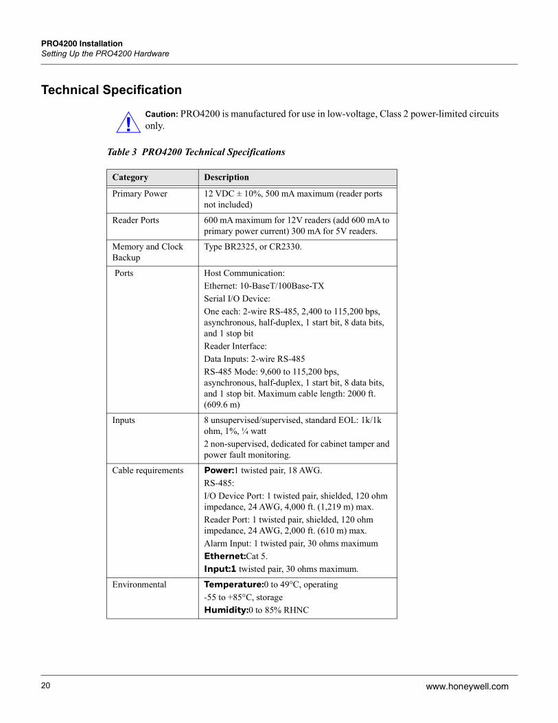
Table 3 PRO4200 Technical Specifications
Caution: PRO4200 is manufactured for use in low-voltage, Class 2 power-limited circuits only.
Category Description
Primary Power 12 VDC ± 10%, 500 mA maximum (reader ports not included)
Reader Ports 600 mA maximum for 12V readers (add 600 mA to primary power current) 300 mA for 5V readers.
Memory and Clock Backup
Type BR2325, or CR2330.
Ports Host Communication:Ethernet: 10-BaseT/100Base-TXSerial I/O Device:One each: 2-wire RS-485, 2,400 to 115,200 bps, asynchronous, half-duplex, 1 start bit, 8 data bits, and 1 stop bitReader Interface:Data Inputs: 2-wire RS-485RS-485 Mode: 9,600 to 115,200 bps, asynchronous, half-duplex, 1 start bit, 8 data bits, and 1 stop bit. Maximum cable length: 2000 ft. (609.6 m)
Inputs 8 unsupervised/supervised, standard EOL: 1k/1k ohm, 1%, ¼ watt2 non-supervised, dedicated for cabinet tamper and power fault monitoring.
Cable requirements Power:1 twisted pair, 18 AWG.RS-485:I/O Device Port: 1 twisted pair, shielded, 120 ohm impedance, 24 AWG, 4,000 ft. (1,219 m) max.Reader Port: 1 twisted pair, shielded, 120 ohm impedance, 24 AWG, 2,000 ft. (610 m) max.Alarm Input: 1 twisted pair, 30 ohms maximumEthernet:Cat 5.Input:1 twisted pair, 30 ohms maximum.
Environmental Temperature:0 to 49°C, operating-55 to +85°C, storageHumidity:0 to 85% RHNC
PRO4200 InstallationSetting Up the PRO4200 Hardware
PRO4200 (PRO42IC) Installation and Configuration Guide, Document 800-25695V1 21
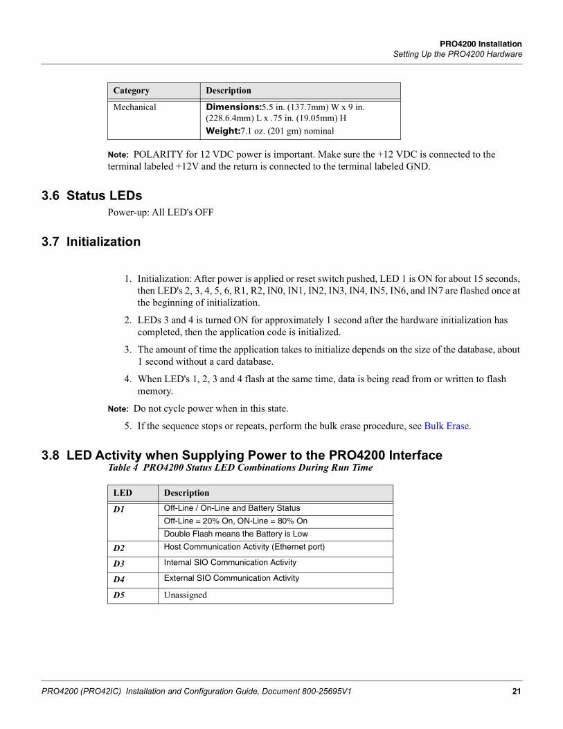
Note: POLARITY for 12 VDC power is important. Make sure the +12 VDC is connected to the terminal labeled +12V and the return is connected to the terminal labeled GND.
3.6 Status LEDs Power-up: All LED's OFF
3.7 Initialization
1. Initialization: After power is applied or reset switch pushed, LED 1 is ON for about 15 seconds, then LED's 2, 3, 4, 5, 6, R1, R2, IN0, IN1, IN2, IN3, IN4, IN5, IN6, and IN7 are flashed once at the beginning of initialization.
2. LEDs 3 and 4 is turned ON for approximately 1 second after the hardware initialization has completed, then the application code is initialized.
3. The amount of time the application takes to initialize depends on the size of the database, about 1 second without a card database.
4. When LED's 1, 2, 3 and 4 flash at the same time, data is being read from or written to flash memory.
Note: Do not cycle power when in this state.
5. If the sequence stops or repeats, perform the bulk erase procedure, see Bulk Erase.
3.8 LED Activity when Supplying Power to the PRO4200 InterfaceTable 4 PRO4200 Status LED Combinations During Run Time
Mechanical Dimensions:5.5 in. (137.7mm) W x 9 in. (228.6.4mm) L x .75 in. (19.05mm) HWeight:7.1 oz. (201 gm) nominal
Category Description
LED Description
D1 Off-Line / On-Line and Battery Status
Off-Line = 20% On, ON-Line = 80% On
Double Flash means the Battery is Low
D2 Host Communication Activity (Ethernet port)
D3 Internal SIO Communication Activity
D4 External SIO Communication Activity
D5 Unassigned

22
PRO4200 InstallationSetting Up the PRO4200 Hardware
www.honeywell.com
3.9 Supplying Power to the PRO4200 InterfaceThe processor accepts 12 VDC for power. Locate power source as close to the unit as possible and connect it with minimum of 18AWG wires.
D6 Reader 0:Clock/Data or D1/Do mode: Flashes when Data is Received, Either Input F/2F Mode: Flashes when Transmitting Data/Acknowledgment is Received Rs-485 Mode (OSDP): Flashes when Transmitting Data
D7 Reader 1:Clock/Data or D1/D0 Mode: Flashes when Data is Revived, Either Input F?2F Mode: when Data/Acknowledgment is Received RS-485 Mode (OSDP): Flashes when Transmitting Data
D8 Input IN0 Status: OFF = Inactive, ON = Active, Flash = Fault*
D9 Input IN1 Status: OFF = Inactive, ON = Active, Flash = Fault*
D10 Input IN2 Status: OFF = Inactive, ON = Active, Flash = Fault*
D11 Input IN3 Status: OFF = Inactive, ON = Active, Flash = Fault*
D12 Input IN4 Status: OFF = Inactive, ON = Active, Flash = Fault*
D13 Input IN5 Status: OFF = Inactive, ON = Active, Flash = Fault*
D14 Input IN6 Status: OFF = Inactive, ON = Active, Flash = Fault*
D15 Input IN7 Status: OFF = Inactive, ON = Active, Flash = Fault*
D17 RelayK0:ON = Energized, Door Relay
D18 Relay K1: ON = Energized, Door Relay
D19 Relay K2: ON = Energized
D20 Relay K3: ON = Energized
D23 Flashes with Ethernet Traffic
LED Description
Caution: Observe POLARITY on 12 VDC.
Caution: ATTENTION: Observez la polarité du 12 VCC

PRO4200 InstallationSetting Up the PRO4200 Hardware
PRO4200 (PRO42IC) Installation and Configuration Guide, Document 800-25695V1 23
Figure 2: PRO4200 Power Terminals
3.10 Communications WiringThe PRO4200 processor communicates to the host via on-board Ethernet 10Base-T/100Base-TX port.The serial I/O device communication port (TB1) is a 2-wire RS-485 interface which can be used to connect additional I/O panels. The interface allows multi-drop communication on a single bus of up to 4,000 feet (1,219 m). Use 1-twisted pair with drain wire and shield, 120-ohm impedance, 24 AWG, 4,000 ft. (1,219 m) maximum for communication.

24
PRO4200 InstallationSetting Up the PRO4200 Hardware
www.honeywell.com
Figure 3: PRO4200 Port Wiring
3.11 Cabinet Tamper and Power Failure Input WiringFigure 4: PRO4200 TMP and FLT Terminals
Inputs TMP and FLT are used for monitoring cabinet tamper and power failure with normally closed contacts. These two inputs are for contact closure monitoring only; do not use end-of-line (EOL) resistor(s). If these inputs are not used, install a short piece of wire at the input to indicate a safe condition.
3.12 Memory and Real Time Clock Backup BatteryThe event log buffer and the real time clock are backed up by BR2325. This BR2325, BR2330, or CR2330 battery should be replaced annually. A replacement battery may be obtained However, the replacement battery must be UL recognized.
Warning: Battery may explode if mistreated. DO NOT RECHARGE, DISASSEMBLE or DISPOSE OF IN FIRE!
PRO4200 InstallationSystem Configuration via Web Interface
PRO4200 (PRO42IC) Installation and Configuration Guide, Document 800-25695V1 25
4 System Configuration via Web InterfaceThe PRO4200 comes with Access Control Device Server Manager (ACDSM). The ACDSM is a built-in web server, through which you can configure network and other system settings.
Notes:
• If you are using Internet Explorer Enhanced Security Configuration, you cannot access the ACDSM web server. All pages will display “Bad Request!” You must uninstall the Enhanced Security option before you can access the ACDSM.
• The default factory-set TCP/IP address for the built-in system configuration web server is 192.168.0.251
4.1 Connecting to ACDSM for the First Time1. Use the factory default controller IP address 192.168.0.251.
2. Set the DIP switches to S4=OFF, S3=OFF, S2=ON, S1=OFF.
Note: S1 must be set to OFF for the factory default. After the panel powers up, change S1 to ON to enable the use of the default user name and password.
3. Connect the computer to host the web server via Ethernet Port 0. Connection should be via crossover Ethernet cable or by the regular Ethernet cables connected via the hub.
4. Set the host computer to the static IP address 192.168.0.250 to be able to connect to the factory-default PRO4200 controller at address 192.168.0.251.
5. Power up the PRO4200 controller.
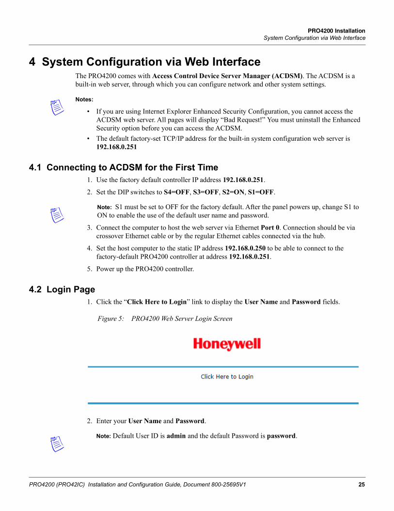
4.2 Login Page1. Click the “Click Here to Login” link to display the User Name and Password fields.
Figure 5: PRO4200 Web Server Login Screen
2. Enter your User Name and Password.
Note: Default User ID is admin and the default Password is password.
26
PRO4200 InstallationSystem Configuration via Web Interface
www.honeywell.com
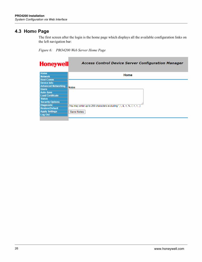
4.3 Home PageThe first screen after the login is the home page which displays all the available configuration links on the left navigation bar:
Figure 6: PRO4200 Web Server Home Page
PRO4200 InstallationSystem Configuration via Web Interface
PRO4200 (PRO42IC) Installation and Configuration Guide, Document 800-25695V1 27
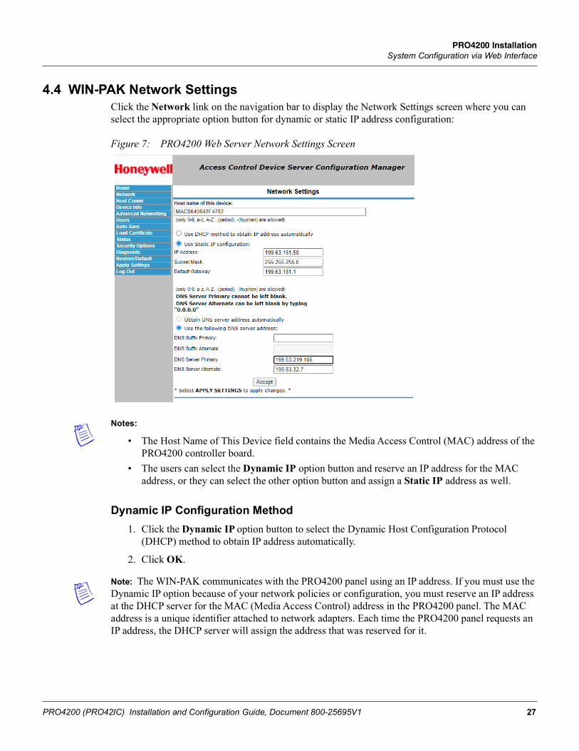
4.4 WIN-PAK Network SettingsClick the Network link on the navigation bar to display the Network Settings screen where you can select the appropriate option button for dynamic or static IP address configuration:
Figure 7: PRO4200 Web Server Network Settings Screen
Notes:
• The Host Name of This Device field contains the Media Access Control (MAC) address of the PRO4200 controller board.
• The users can select the Dynamic IP option button and reserve an IP address for the MAC address, or they can select the other option button and assign a Static IP address as well.
Dynamic IP Configuration Method1. Click the Dynamic IP option button to select the Dynamic Host Configuration Protocol
(DHCP) method to obtain IP address automatically.
2. Click OK.
Note: The WIN-PAK communicates with the PRO4200 panel using an IP address. If you must use the Dynamic IP option because of your network policies or configuration, you must reserve an IP address at the DHCP server for the MAC (Media Access Control) address in the PRO4200 panel. The MAC address is a unique identifier attached to network adapters. Each time the PRO4200 panel requests an IP address, the DHCP server will assign the address that was reserved for it.
28
PRO4200 InstallationSystem Configuration via Web Interface
www.honeywell.com
Static IP Configuration Method1. Click the Static IP option button to assign a static IP address, and enter the following
information in the appropriate fields:
• IP Address
• Subnet Mask
• Default Gateway
2. Click OK.
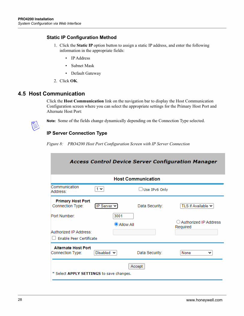
4.5 Host CommunicationClick the Host Communication link on the navigation bar to display the Host Communication Configuration screen where you can select the appropriate settings for the Primary Host Port and Alternate Host Port:
Note: Some of the fields change dynamically depending on the Connection Type selected.
IP Server Connection Type
Figure 8: PRO4200 Host Port Configuration Screen with IP Server Connection

PRO4200 InstallationSystem Configuration via Web Interface
PRO4200 (PRO42IC) Installation and Configuration Guide, Document 800-25695V1 29
1. From PRO4200 Communication Address drop-down list, select one of the eight (0 to 7) available communication addresses for the PRO4200 board.
Note: In the previous panels, this selection was made manually by setting the DIP switches.
2. For the Primary Host Port, make the following selections:
• Connection Type. Select IP Server (the standard connection type), so that the WIN-PAK Host will poll the PRO4200 panel. The panel does not currently support the IP Client option, which would cause the PRO4200 panel to poll the WIN-PAK Host and the Host to reply to the panel.
• Data Security. Select one of the following:• None• Password/AES from the drop-down list. If you select Password/AES, communications
between the WIN-PAK Host and the PRO4200 panel are encrypted. Note that encryption must be enabled in WIN-PAK for the appropriate WIN-PAK channel. See Chapter 7, “Hardware Configuration,” in the WIN-PAK Guide for channel encryption instructions.
• Port Number. Enter the port number through which the host computer can communicate with the PRO4200 board.
• Select either Allow All or the Authorized IP Address Required option button.
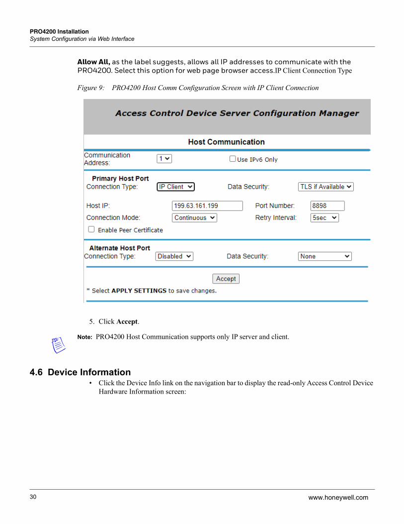
3. Allow All, as the label suggests, allows all IP addresses to communicate with the PRO4200. Select this option for web page browser access.
4. For the Primary Host Port, make the following selections:
• Connection Type. Select IP Server (the standard connection type), so that the WIN-PAK Host will poll the PRO4200 panel. The panel does not currently support the IP Client option, which would cause the PRO4200 panel to poll the WIN-PAK Host and the Host to reply to the panel.
• Data Security. Select one of the following:
• None
• Password/AES from the drop-down list. If you select Password/AES, communications between the WIN-PAK Host and the PRO4200 panel are encrypted. Note that encryption must be enabled in WIN-PAK for the appropriate WIN-PAK channel. See Chapter 7, “Hardware Configuration,” in the WIN-PAK Guide for channel encryption instructions.
• Port Number. Enter the port number through which the host computer can communicate with the PRO4200 board.
• Select either Allow All or the Authorized IP Address Required option button.
30
PRO4200 InstallationSystem Configuration via Web Interface
www.honeywell.com
Allow All, as the label suggests, allows all IP addresses to communicate with the PRO4200. Select this option for web page browser access.IP Client Connection Type
Figure 9: PRO4200 Host Comm Configuration Screen with IP Client Connection
5. Click Accept.
Note: PRO4200 Host Communication supports only IP server and client.
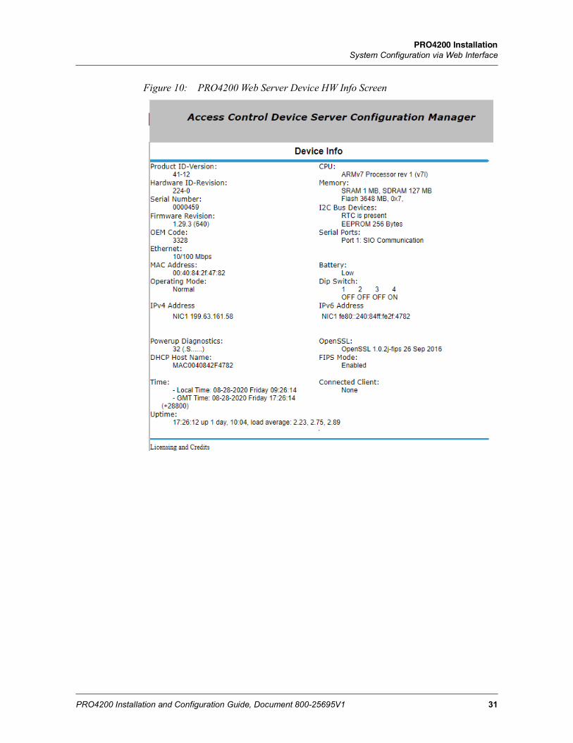
4.6 Device Information• Click the Device Info link on the navigation bar to display the read-only Access Control Device
Hardware Information screen:
PRO4200 InstallationSystem Configuration via Web Interface
PRO4200 Installation and Configuration Guide, Document 800-25695V1 31
Figure 10: PRO4200 Web Server Device HW Info Screen
32
PRO4200 InstallationSystem Configuration via Web Interface
www.honeywell.com
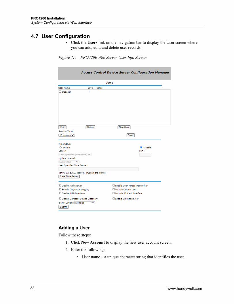
4.7 User Configuration• Click the Users link on the navigation bar to display the User screen where
you can add, edit, and delete user records:
Figure 11: PRO4200 Web Server User Info Screen
Adding a UserFollow these steps:
1. Click New Account to display the new user account screen.
2. Enter the following:
• User name – a unique character string that identifies the user.
PRO4200 InstallationSystem Configuration via Web Interface
PRO4200 Installation and Configuration Guide, Document 800-25695V1 33
• Level – level of privileges the user will have. Level 1 grants the user read/write privileges to all panel features; level 2 grants the user read-only privileges to the Notes, Network, Host Port, and Device Info features; level 3 grants the user read-only privileges to just the Notes and Device Info features.
3. Specify the maximum period of time a session will remain open without user activity. If the period expires without user activity, the user is logged out. After specifying the time period, click Save Session Timer to save the setting.
4. Configure the auto-save timer. This feature, if enabled, automatically saves the hardware configuration in non-volatile Random Access Memory (RAM) at the specified time interval. If you select Enable Auto-Save, then select a time interval from the drop-down list, and click Save Auto-Save Timer to save the setting.
Editing a UserTo edit a user record, click to select the user from the Username column and then click Edit. Use the information provided in the previous section, “Adding a User,” to edit the record.
Deleting a UserTo delete a user record, click to select the user from the Username column and then click Delete.
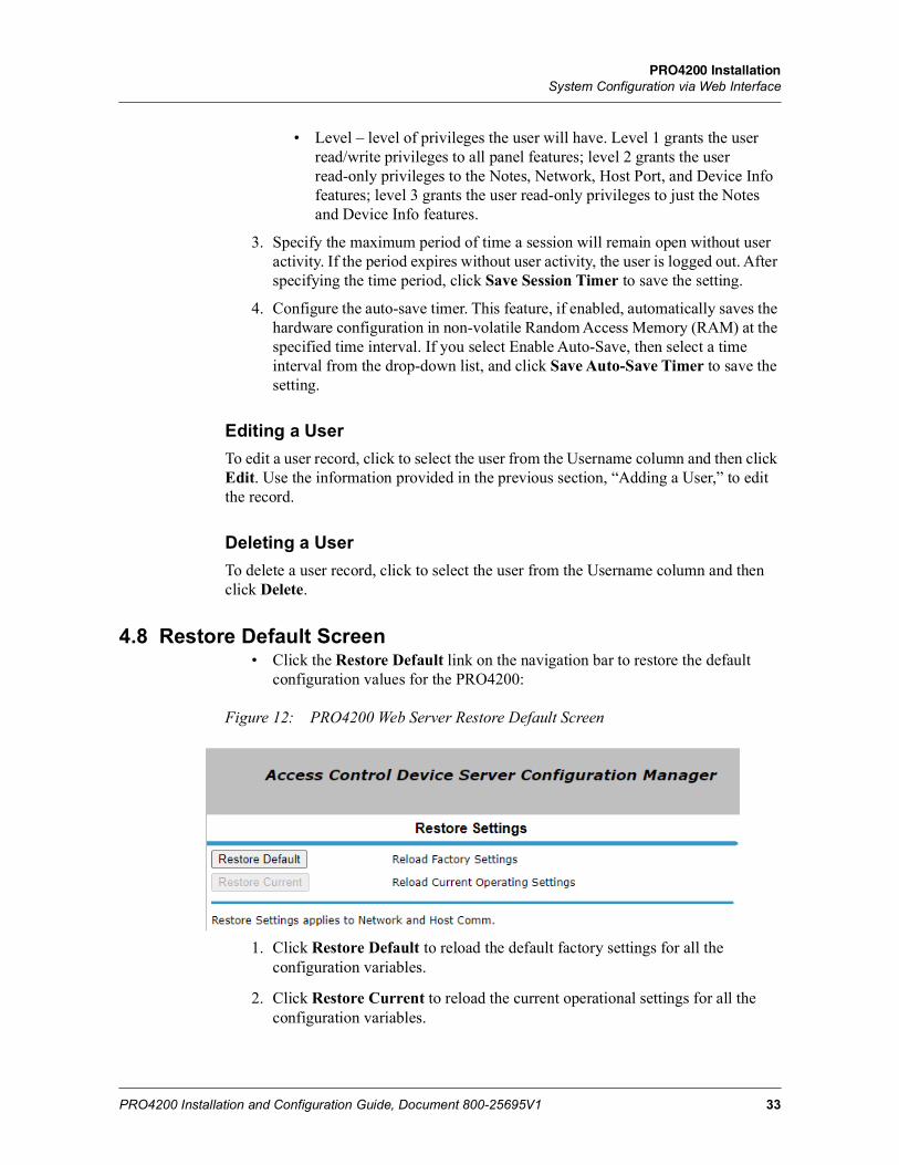
4.8 Restore Default Screen • Click the Restore Default link on the navigation bar to restore the default
configuration values for the PRO4200:
Figure 12: PRO4200 Web Server Restore Default Screen
1. Click Restore Default to reload the default factory settings for all the configuration variables.
2. Click Restore Current to reload the current operational settings for all the configuration variables.
34
PRO4200 InstallationSystem Configuration via Web Interface
www.honeywell.com
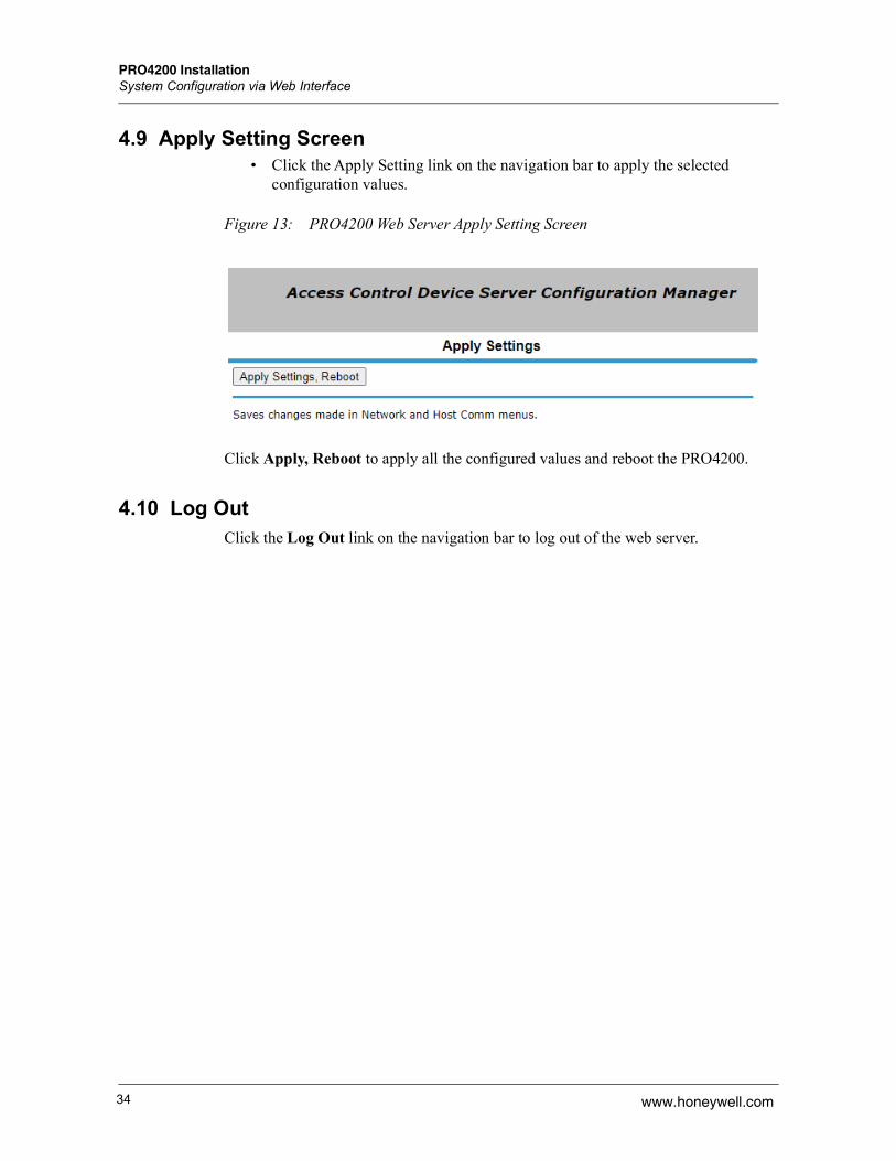
4.9 Apply Setting Screen• Click the Apply Setting link on the navigation bar to apply the selected
configuration values.
Figure 13: PRO4200 Web Server Apply Setting Screen
Click Apply, Reboot to apply all the configured values and reboot the PRO4200.
4.10 Log OutClick the Log Out link on the navigation bar to log out of the web server.

PRO4200 InstallationReader Module
PRO4200 Installation and Configuration Guide, Document 800-25695V1 35
5 Reader ModuleFigure 14: PRO4200 Intelligent Controller Module Wiring: Connectors TB1,TB3-9.
Note: See Status LEDs (see page 20) for descriptions of LEDs D1-D20.
Note: For RS-485 Communication Connections, twist the blue pair together and use as the common; use the orange pair as your data pair, observing polarity. Connect the external drain shield to the appropriate earth ground on one end.
DIP
SW
ITCH
ES
ON
OFF
43
21
IC BOARD
EOL
EOL
Door Status Switch
Typical Connection
Egress Push-Button
Switch
REDBLACK
BLACK
RED
WHITEGREEN
S-4Suppressor
S-4Suppressor
Door Lock
Door Lock
Separate Power Supply
-VDC
+
-VDC
+
KP-13WeigandKeypad
Proximity Reader
Chassis GND Inside Panel
Chassis GND Inside Panel
Voltage is selected by Jumper J7 On Board
Voltage is selected by Jumper J7 On Board
REDBROWNYELLOWWHITE
GREEN
BLACKDRAIN
REDBROWNYELLOWWHITE
GREEN
BLACKDRAIN
BLACK
RED
Separate Power Supply
BATTERY
J9 BATTERY
ON
OFF
D5
D6
D7
D8
D9
D10
D11
D12
D13
D14
READER1 V+READER1 LEDREADER1 BZRREADER1 D1READER1 D0READER1 GND
IN2IN2 COMMONIN3IN3 COMMONRELAY2 NORELAY2 CRELAY2 NCRELAY3 NORELAY3 CRELAY3 NC
READER0 V+READER0 LEDREADER0 BZRREADER0 D1READER0 D0READER0 GND
IN4IN4 COMMONIN5IN5 COMMON
IN0IN0 COMMONIN1IN1 COMMONRELAY0 NORELAY0 CRELAY0 NCRELAY1 NORELAY1 CRELAY1 NC
IN6IN6 COMMONIN7IN7 COMMON
K 1
K 2
K 2
J 8
J 7
J 4 PINS
123456
123456
1234
123456789
10
123456789
10
1234
123
Tamper Switch (In CLOSE
position when Cabinet Door is
Closed)
Short together*
N/C - Low BatteryC - Low Battery
+12VDC Power Supply
_
C - No ChargingN/C - No Charging
+ PWR+
PWR-DC Output
The connectors on this side of the board are not accessible when it is rack
mounted.
TMPGNDPFL
Pow
erR
S-485
D1
D2
D3
D4
J 5 - RS-485Termination
CardRack PWR &
Com Harness* (Rack Mount Only)
12345
PWR+
PWR-
Ethernet Connector
RS-485 TR+RS-4845 TR-RS-485 GND
+ 12VGND
K3K
2K4

36
PRO4200 InstallationReader Module
www.honeywell.com
Note: Reader, Input, and Output addresses on the PRO4200 panel are labeled starting with address 0. This translates to address 1 in the WIN-PAK per the example below:
Note: The SIO board port for a PRO42IC in WIN-PAK is port 6 and is set as the default.
5.1 Reader WiringThe following Honeywell reader module numbers have been approved by UL for use with the PRO42IC: OM40BHONA, OM55BHONA, OP10HONE, OP30HONE, OP40HONE, OP90HONE, OT30HONA, OT31HONA, OT35HONA, and OT36HONA.
Each reader port supports a reader with TTL interface. Power to the reader is selectable as 5VDC or 12VDC (pass-through). This selection is done by setting the jumpers J2 for reader 0 and J3 for reader 1. Set jumper at position “5” for 5VDC or “12” for pass-through 12VDC. The factory defaults set J2 and J3 to “5”.
For wiring to a reader port:Table 5 Settings for Wiring to a Reader Port
The LED control terminal in each reader port can be configured via host software to support one-wire single or bi-colored reader LED. An example of the most common configuration is shown below. If Beeper Control is not used, its terminal can be programmed to be the second wire for the two-wire bi-colored reader LED.Table 6 Settings for Configuring an LED Control Terminal
To fully utilize each reader port, a 6-conductor cable (18AWG) is required. Reader port configuration is set via host software.
PRO4200 Device PRO4200 Address WIN-PAK AddressReader\ Input\ Output 0 1Reader\ Input\ Output 1 2
Terminal
Typical Wire Color
Wiegand Reader Clock/Data Reader
1 Red Power (5 or 12 Vdc)
Power (5 or 12 Vdc)
2 Brown LED control LED control
3 Yellow Beeper Control Beeper Control
4 White Data 1 Signal Clock Signal
5 Green Data 0 Signal Data Signal
6 Black Common Common
LED Output-> High Tri-Stated Low
Single Color LED LED On LED Off LED Off
Bi-Color LED Green LED On Both LEDs Off Red LED On

PRO4200 InstallationReader Module
PRO4200 Installation and Configuration Guide, Document 800-25695V1 37
5.2 Input WiringInputs 0 to 7 may be configured to use normally open or normally closed contacts and non-supervised or supervised (with standard ±1% tolerance 1K ohm). Four of these inputs have default functional definitions, but all eight can be configured to monitor general-purpose sensors.
Figure 15: PRO4200 Input wiring
By default, Input 0 is defined as the Door Status Input corresponding to reader 0 and Input 1 is defined as the REX input corresponding to reader 0. Also by default, Input 2 is defined as the Door Status Input corresponding to reader 1 and Input 3 is defined as the REX input corresponding to reader 1.
Inputs 4, 5, 6 and 7 are general purpose inputs that can be used to monitor sensors or as control inputs. Inputs 6 and 7 are not accessible when the board is rack mounted.
Inputs TMP and PFL are typically used for monitoring cabinet tamper and power failure respectively. These two inputs are not supervised and are not accessible when the board is rack-mounted. These inputs were primarily provided for the case when this board is mounted remotely and cannot take advantage of the tamper and power fail detect inputs on the controller board. If these inputs are not used, install a short piece of wire at the input to indicate safe condition.
Input configuration including debounce and hold time is set via host software.
5.3 Control Output WiringFour form-C relay contacts are provided for controlling door strike or other devices. Each may be assigned to door-related functions or general-purpose output. They are configurable as standard (energize to activate) or fail-safe (de-energize to activate) via host software.
The energized or ON time of each relay can be configured using Pulse control for single or repeating pulses via host software. The energized or ON time for a single pulse can be extended up to 24 hours. For repeating pulses, the on/off time can be defined in 0.1 second increments and be repeated up to 255 times.
Relays 0 and 2 are rated for and normally used to control the door locks associated with readers 0 and 1 respectively. While Relays 0 and 2 are sized to handle the typical loads generated by electrical locks, load switching can cause abnormal contact wear and premature contact failure. Switching of inductive loads (i.e., strike) also causes EMI (electromagnetic interference) which may interfere with normal operation of other equipment. To minimize premature contact failure and to increase system
38
PRO4200 InstallationReader Module
www.honeywell.com
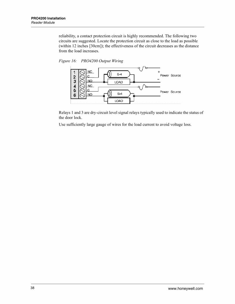
reliability, a contact protection circuit is highly recommended. The following two circuits are suggested. Locate the protection circuit as close to the load as possible (within 12 inches [30cm]); the effectiveness of the circuit decreases as the distance from the load increases.
Figure 16: PRO4200 Output Wiring
Relays 1 and 3 are dry-circuit level signal relays typically used to indicate the status of the door lock.Use sufficiently large gauge of wires for the load current to avoid voltage loss.

(This page is Intentionally left blank)
For more information: www.honeywellaccess.com

Discover | Customer PortalSelf-Service Product Support and Learning Management Systemhttps://honeywelldiscovertraining.com/login/discover/default.asp
YouTube | Honeywell Help and Supporthttps://www.youtube.com/channel/UCBEL6ouNV_LN5lEpYRujMTg/featured
Honeywell Access Systems135 W. Forest Hill AvenueOak Creek, WI 53154414-766-1700414-766-1798 Fax
European OfficeBoblingerstrasse 17D-71101 SchonaichGermany49-7031-637-78249-7031-637-769 Faxwww.honeywell.com
Specifications subject to changewithout notice.
© 2020 Honeywell. All rights reserved.800-25695V1