Embed Size (px)
Citation preview

1
INSTALLATION and OPERATINGINSTRUCTIONS
Controller Unit ESP-MC
Introduction
Welcome to Rain Bird! Thank you for purchasing your new, state-of-the-art Rain Birdcontroller. For more than six decades, Rain Bird has led the irrigation industry in meet-ing all of your water management needs by providing the highest quality products andservices available. Your new Rain Bird controller is designed to give you a lifetime ofon-site watering control.
2
The ESP-MC Controller
The Extra Simple Programming-MAXICOM Compatible series (ESP-MC) controller is astand-alone controller appropriate for residential or commercial use. Its easy-to-usebuilt-in computer offers four programs for up to 40 watering stations. The ESP-MC canalso be upgraded to function as a satellite controller that is part of the MAXICOM irri-gation system.
For more information about using your controller with the MAXICOM system, see theESP-SAT Installation and Operating Instructions manual that comes with the ESP-SATand with the MAXICOM interface board (MIB) for the ESP-MC.
Special Features
The ESP-MC is available as a wall-mount (WM) model in 8, 12, 16, 24, 32, or 40 sta-tion capability. For information about pedestals, contact your Rain Bird distributor. AllESP-MC models have the following special features:
• Anti-rust, corrosion-resistant design• Four independent programs• Cycle + Soak feature for water conservation and erosion control• Program and time keeping during power outage• Diagnostic circuit breaker that identifies a station with a short circuit• Convenient Test Program• Rain Delay from 1 to 99 days• 365-day calendar with various scheduling options for watering cycles• Option to set any day of the month as a non-watering day• Cycle and fault indicator lights• Easy-to-read liquid crystal display• Optional moisture sensors that suspend watering when the soil is wet• Universal remote-ready connections• True independent day cycles by program• Programmable program overlap• Station timing from one minute to 12 hours
Packing List
Please check to make sure that you have all the items on the list. If any item is missingor damaged, contact your Rain Bird distributor.
• 1 Pre-assembled Controller in Wall Cabinet• 1 Bag of Mounting Hardware• 2 Keys• 1 9-Volt Rechargeable Battery• 1 Installation and Operating Instructions Manual• 1 Mounting Template• 1 Three-year Warranty Card
3
Chapter 1: Installation
This section of the manual explains how to mount your new ESP-MC controller on thewall and how to connect the wiring.
Mounting the ControllerBefore You Begin
Important: Before installing your controller, make sure that the area around you isfree from dirt and dust and that your hands and arms are clean. This will avoid con-tamination of the controller’s internal parts.
Warning! Do not let water or other liquids come in contact with any part inside themetal cabinet.
Choosing a Location
When choosing the best location to install your wall-mount controller, please considerthe following:
Warning! This controller must be installed in compliance with local electrical codes.
ü Select an area, protected from vandalism, where the user can easily reach the con-troller. We recommend placing the controller in a utility room.
ü Select a location that has access to 120 volt AC electrical power (or the properelectrical supply voltage outside the United States).
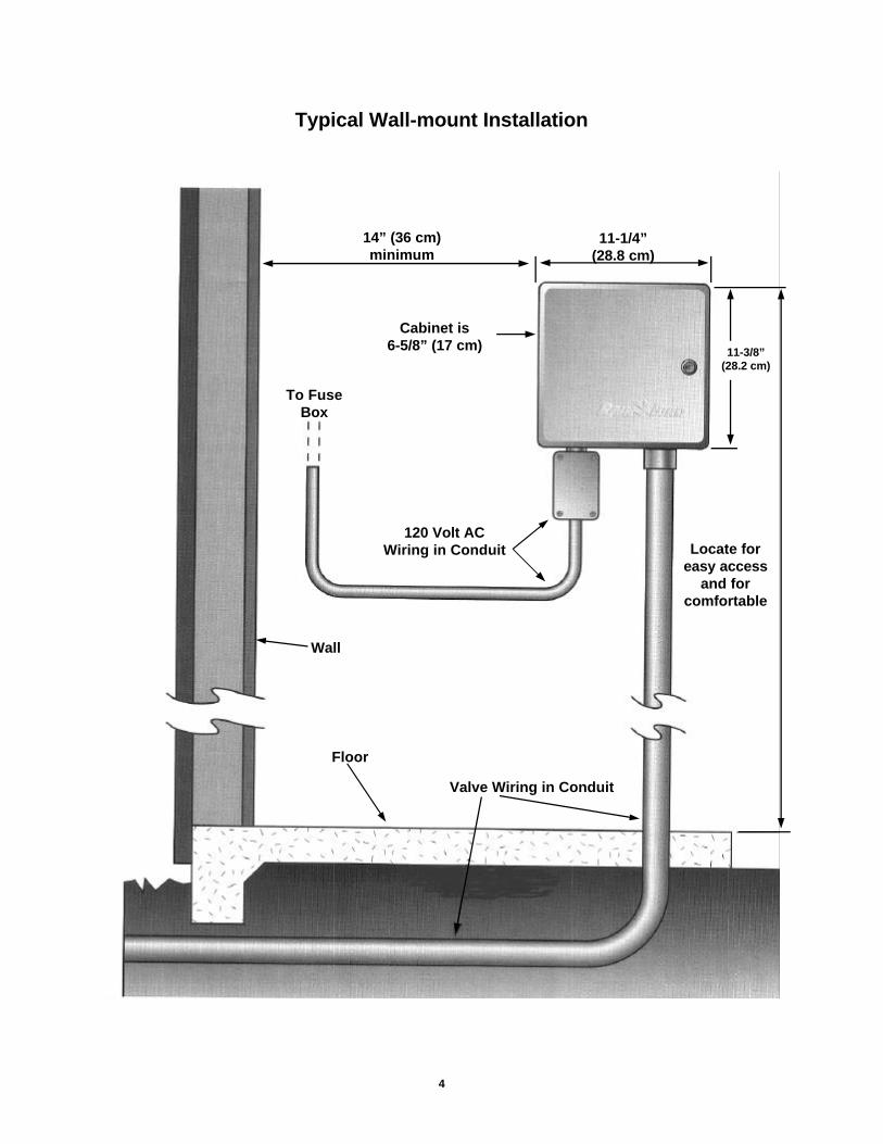
ü Choose a flat, stable, vertical surface, where you can mount the controller. Allowsufficient conduit clearance for the electrical connections at the bottom of the metalcabinet.
ü Allow 14” (35.9 cm) minimum clearance for the hinged cabinet door to swing fully tothe left.
What You Will Need
Before you begin installation, you will need the following tools:
ü Phillips Head Screwdriverü Slotted Head Screwdriverü Slotted Thin Blade Screwdriverü Wire Strippersü Lineman’s Pliersü Needlenose Pliersü Tape Measureü Marking Pencilü Electric Drill (or Hammer Drill if installing in masonry or concrete wall)ü Nut Driver
4
14” (36 cm)minimum
11-1/4”(28.8 cm)
Cabinet is6-5/8” (17 cm)
To FuseBox
Wall
Floor
Valve Wiring in Conduit
120 Volt ACWiring in Conduit
11-3/8”(28.2 cm)
Locate foreasy access
and forcomfortable
Typical Wall-mount Installation
5
Chapter 1: Installation (Continued)
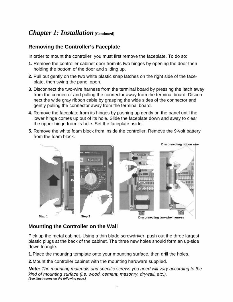
Removing the Controller’s Faceplate
In order to mount the controller, you must first remove the faceplate. To do so:
1. Remove the controller cabinet door from its two hinges by opening the door thenholding the bottom of the door and sliding up.
2. Pull out gently on the two white plastic snap latches on the right side of the face-plate, then swing the panel open.
3. Disconnect the two-wire harness from the terminal board by pressing the latch awayfrom the connector and pulling the connector away from the terminal board. Discon-nect the wide gray ribbon cable by grasping the wide sides of the connector andgently pulling the connector away from the terminal board.
4. Remove the faceplate from its hinges by pushing up gently on the panel until thelower hinge comes up out of its hole. Slide the faceplate down and away to clearthe upper hinge from its hole. Set the faceplate aside.
5. Remove the white foam block from inside the controller. Remove the 9-volt batteryfrom the foam block.
Mounting the Controller on the Wall
Pick up the metal cabinet. Using a thin blade screwdriver, push out the three largestplastic plugs at the back of the cabinet. The three new holes should form an up-sidedown triangle.
1.Place the mounting template onto your mounting surface, then drill the holes.
2.Mount the controller cabinet with the mounting hardware supplied.
Note: The mounting materials and specific screws you need will vary according to thekind of mounting surface (i.e. wood, cement, masonry, drywall, etc.).(See illustrations on the following page.)
Step 1 Step 2 Disconnecting two-wire harness
Disconnecting ribbon wire

6
Connecting the Controller
There are three types of connections you must make to your ESP-MC controller:
• connections to the field valves,• grounding connections, and• connections to the main power source.
You may also want to connect an optional sensor, which prevents watering duringrainfall or when the soil is moist.
This section of the manual contains instructions for all four types of connections.
Note: If you are installing an ESP-SAT controller, see the ESP-SAT Installation andOperating Instructions Manual for information about connecting the controller to thecluster control unit.
Important: All wiring must be installed and connected in accordance with local codes.
Connections to the Field Valves
Each valve that is controlled by the ESP-MC must have its own wire that is connectedto a numbered station terminal on the controller’s terminal strip. Each station terminalis capable of operating two valves.
Important: The wires you use to connect the controller to the field valves must be ap-proved for underground use. See the Rain Bird catalog for exact wire specifications.
Important: Do not install the valve wires in the same conduit as the wires to the mainpower source.
The illustrations below demonstrate Mounting the Controller.Remove the faceplate from hinges Three plastic plugs

7
To connect the valve wires:
1. Feed each valve wire up through the large hole on the bottom of the controller cabi-net.
2. Strip 1/2” (1.3 cm) from the end of the valve wire. Insert the wire into the appropriatestation terminal. If the wire does not enter securely into the hole, press down on theorange lever as you insert the wire.
Note: Each station has two holes (one above the other) because each station is capa-ble of operating two valves.
3.Repeat for all used stations.
4.Attach the valve common wire to one of the two common terminals in the same way.
5. If your system includes a master valve or a 24 volt pump start relay, connect thewire from that device to the MV (master valve) terminal on the controller the sameway you connected the other wires.
Note: MV2 (master valve 2) is enabled when any station operates. MV1 (master valve
Personal Wiring Notes:
_______________________________________________________________________________________________________
_______________________________________________________________________________________________________
_______________________________________________________________________________________________________
_______________________________________________________________________________________________________
_______________________________________________________________________________________________________
_______________________________________________________________________________________________________
_______________________________________________________________________________________________________
Insertion of the Valve Wire:

8
Grounding Connections
The ESP-MC is equipped with built-in electrical surge protection. For this system tofunction, the earth ground terminal on the controller must be connected to a groundrod that is driven into the earth.
Important: Use a #10 (6 mm) or #8 (10 mm) bare wire to connect the controller to theground-rod. Use a standard copper clad, 5/8" (1.6 cm) diameter, 8 ' (0.6 m) long rod.
To connect the ground wire,
1. Feed the ground wire up through the large hole at the bottom of the controller cabi-net (the same hole used for the valve wires).
2.Loosen the screw on the copper earth ground terminal and place the ground wireinto the terminal. Tighten the screw so that the ground wire is secure.
Connections to the Main Power Source
The three main power input wires for the standard 117 volt, 60 Hz/AC transformer areblack, white, and green. The international version 230 volt, 50 Hz wires are black,white, and green and yellow. These wires exit the controller through the smaller holeat the bottom of the controller cabinet.
Important: The wires that connect the controller to the main power source must be in-stalled in a conduit other than the one that contains the field wires.
Insertion of the Ground Wire:
Location of Junction Box:
9
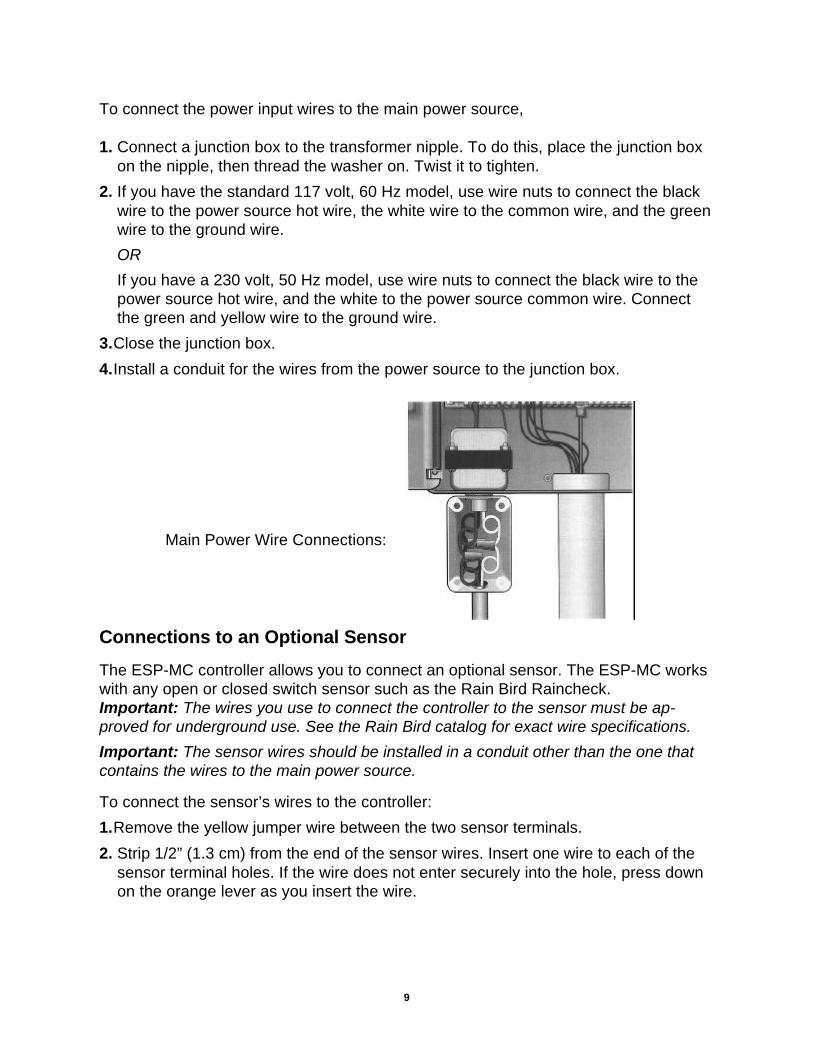
To connect the power input wires to the main power source,
1. Connect a junction box to the transformer nipple. To do this, place the junction boxon the nipple, then thread the washer on. Twist it to tighten.
2. If you have the standard 117 volt, 60 Hz model, use wire nuts to connect the blackwire to the power source hot wire, the white wire to the common wire, and the greenwire to the ground wire.
OR
If you have a 230 volt, 50 Hz model, use wire nuts to connect the black wire to thepower source hot wire, and the white to the power source common wire. Connectthe green and yellow wire to the ground wire.
3.Close the junction box.
4.Install a conduit for the wires from the power source to the junction box.
Main Power Wire Connections:
Connections to an Optional Sensor
The ESP-MC controller allows you to connect an optional sensor. The ESP-MC workswith any open or closed switch sensor such as the Rain Bird Raincheck.Important: The wires you use to connect the controller to the sensor must be ap-proved for underground use. See the Rain Bird catalog for exact wire specifications.
Important: The sensor wires should be installed in a conduit other than the one thatcontains the wires to the main power source.
To connect the sensor’s wires to the controller:
1.Remove the yellow jumper wire between the two sensor terminals.
2. Strip 1/2” (1.3 cm) from the end of the sensor wires. Insert one wire to each of thesensor terminal holes. If the wire does not enter securely into the hole, press downon the orange lever as you insert the wire.

10
Connecting the sensor’s wires to the controller (Continued)
3. Route the wires out of the controller through the large hole at the bottom of the con-troller cabinet
4.Connect the other end of the wires to the sensor’s valve common terminals or wires.
5.Follow the sensor’s directions for placing and connecting the sensor’s probes andfor setting the shutoff level, if appropriate.
Putting the Controller Back Together
Congratulations! You have completed the mounting and wiring of your new ESP-MCcontroller. To put the controller back together:
1. Replace the controller’s face plate by slipping it into the hinges.
2. Plug the two-wire connector and the ribbon cable connector back into the terminalboard.
3. Detach the recharging clip from its retainer at the back of the face plate. Snap therecharging clip onto the 9 volt battery supplied. Then push the battery into the bat-tery holder.
The ESP-MC fully charges the nickel metal hydride, 9 volt battery in about 48 hoursand continues to charge the battery whenever the controller is supplied with power.The 9 volt battery provides power for keeping track of what cycle is in progresswhen there is a power outage. The 9 volt battery also allows the controller to beprogrammed when the face plate is detached from the cabinet. This feature lets theinstaller walk a site while setting watering times and schedules.
Note: The ESP-MC also has a built-in lithium battery that provides for non-volatileprogram memory.
Warning! Do not use an alkaline battery in the controller; alkaline batteries can causean explosion.
4.Re-attach the controller door to its hinges.
Sensor Wire Connection (Step 1):
11
Chapter 2: Programming & Operation
Using the buttons and dial on the controller's faceplate, you can set up the ESP-MC tooperate automatically. You can also run the controller manually without makingchanges in the programs you have set.
This section will guide you through the use of the controller's buttons and dial and willgive you step-by-step instructions for setting up the four programs to suit your needs,as well as instructions for operating the controller manually.
Familiarizing Yourself with the Controller’s Faceplate
Before beginning to program or operate your controller, take a moment to familiarizeyourself with the controller’s faceplate. The following information contains a short de-scription of each of the buttons and indicators.
WATERING SUSPENDED BY SENSORThis light is on when watering has been suspended by a sensor.
SENSOR OFF/ACTIVEIf you want the sensor to be active, set the switch to ACTIVE. If you wish to overridethe sensor or there is no sensor connected to the controller, set the switch to OFF.
pp / ONPress to turn a setting on or to advance the setting in the display.
qq / OFFPress to turn a setting off or to decrease the setting in the display.
PGMPress to change the program indicator in the display. The indicator cycles throughprograms A, B, C, and D.
MAN START/ADV.Press to advance to the next setting in the display or to start an operation.
FAULT RESETPress to clear the fault reading from the display. Press this button after you have fixedthe short circuit indicated by the diagnostic fault indicator in the display.
STAND ALONE/MAXICOMIf you want your controller to function as a stand-alone unit, set this switch to STANDALONE. If you want it to function as a satellite connected to the MAXICOM system, setthis switch to MAXICOM.
PUMP/MV STATUSThis light is on when the Master Valve 1 (MV1) circuit is enabled for the active station.
STATION STATUSThis light is on when a valve is active.
LINKED TO MAXICOMThis light is on when the STAND ALONE/MAXICOM switch is in the MAXICOM posi-tion and the controller is physically linked to the MAXICOM system.
12
Buttons and indicators (Continued)
EVEN DAY CYCLEThis light is on when the controller’s active program is set to water on even days of themonth.
ODD DAY CYCLEThis light is on when the controller’s active program is set to water on odd days of themonth.
CYCLICAL DAY CYCLEThis light is on when the controller’s active program is set to water in a cycle with aspecified number of days.
CUSTOM DAY CYCLEThis light is on when the controller’s active program is set to water on specific days ofthe week.
AUTOSet the dial here to run the controller automatically on the programs you set.
STATION WATERING TIMESet the dial here to set the length of an individual station’s watering time.
WATERING START TIMESet the dial here to set a program’s watering start times. Eight start times are availablefor each program.
MV PUMP STARTSet the dial here to enable or disable Master Valve 1 (MV1) for a particular station.
PROGRAM OVERLAPSet the dial here to set programs to either stack or overlap. The default for all pro-grams is stack.
TIME/CALENDARSet the dial here to set the time and calendar.
EVENT DAY OFFSet the dial here to set optional day(s) off within the month.
RAIN DELAYSet the dial here to delay watering for a specified number of days.
MON — SUNSet the dial to the day of the week to turn that day off or on when setting a custom pro-gram cycle.
CUSTOMSet the dial here to set a program cycle to water on specific days of the week.
CYCLICALSet the dial here to set a program cycle to water at specific intervals such as everyday, every second day, every third day, etc.
ODD DAYS

13
Buttons and indicators (Continued)
EVEN DAYSSet the dial here to set a program cycle that waters on even days of the month.
WATER BUDGETSet the dial here to set the water budget percentage for a program. 100% is the de-fault.
CYCLE + SOAKSet the dial here to break a station’s watering time into intervals to conserve water andprevent erosion.
TEST PROGRAMSet the dial here to set and start a test program cycle for all stations.
MANUAL WATERINGSet the dial here to water a station manually.
OFFSet the dial here to shut the controller and its valves down, such as during the wintermonths.
Programming the Controller
This section of the manual contains instructions for programming your ESP-MC con-troller. The controller comes from the factory without a pre-set default program.
Before you begin programming, it is a good idea to chart your watering schedule on apiece of paper, taking into account the schedule for all stations and how often youwant to repeat the schedule.
Setting the Clock and Calendar
In order to program the controller, you must first set the controller’s internal clock and
1. Rotate the dial to TIME/CALENDAR. The hourdigits in the display flash, indicating that theyare ready to be set.
2. Use the arrow keys to set the hour to the cur-rent time. If you have a 60 Hz model, as youpass 12:00 the am/pm designation changes.
Note: The 60 Hz model displays time in the 12hour am/pm mode. The 50 Hz model displaystime in the 24 hour military mode.
3. Press MAN START/ADV. The minute digitsflash, indicating that they are ready to be set.
AM

14
Setting Up a Program
There are four program settings available with the ESP-MC: A, B, C, and D. You canset each program to operate according to your specifications. When you set up a pro-gram, you:
• select the program,• choose a cycle setting for the program, and• assign stations and set the station’s watering durations and start times.
Note: It is easier to select a program and program it completely. Jumping from pro-gram to program can be confusing.
Step one: Selecting a program
4. Use the arrow keys to set the minutes to thecurrent time.
5. Press MAN START/ADV.A new display appears with the day, monthand year. The month is flashing, indicatingthat it is ready to be set.
6. Use the arrow keys and the MAN START/ADV key to set the month, day, and year thesame way you set the hour and minutes.
7. Press MAN START/ADV to return to the timeof day display. The hour continues to flashas long as the dial is left at TIME/CALEN-DAR.
8. Return the dial to AUTO. The display showsthe day of the week and time of day.
PM
DAY
1. Press PGM to cycle through the availableprograms. The program indicator on the farleft side of the display changes.
PGM
A
Step two: Selecting the cycle
Each program can operate in one of four cycle modes:
• CUSTOM waters on the days of the week you select• CYCLICAL waters according to a cycle with a specified number of days.• ODD waters only on odd days of the month.• EVEN waters only on even days of the month.
Note: All programs default to the custom cycle.
15
PGM
A
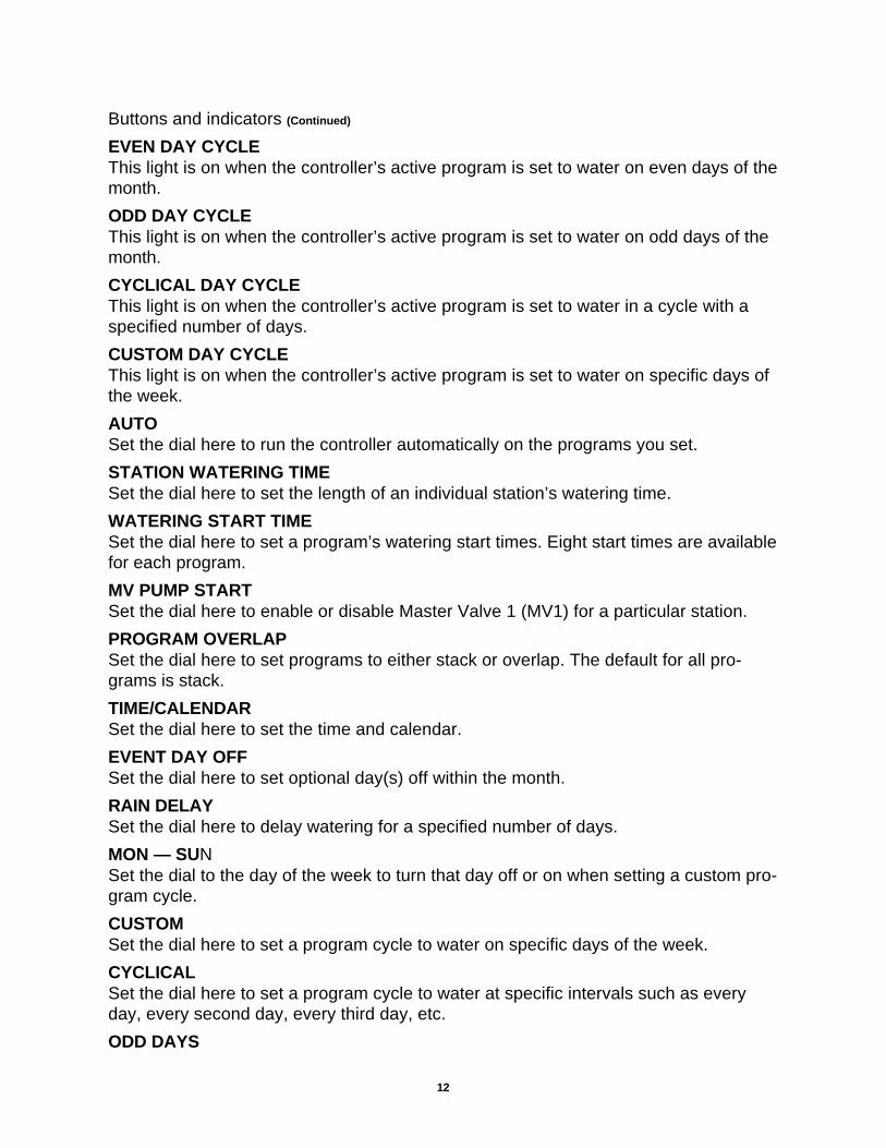
To set a custom cycle:
1. Rotate the dial to CUSTOM. The displayshows the program and CUSTOM. The dis-play shows USED if the program is activeand using a different cycle mode. If so, youcan override the previous setting.
2. If the program you want is not displayed,press PGM until it is.
3. Press ON. The display shows CUSTOM andthe custom light on the faceplate illuminates.
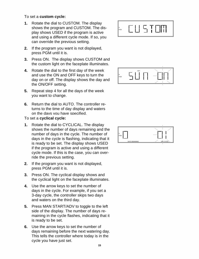
4. Rotate the dial to the first day of the weekand use the ON and OFF keys to turn theday on or off. The display shows the day andthe ON/OFF setting.
5. Repeat step 4 for all the days of the weekyou want to change.
6. Return the dial to AUTO. The controller re-turns to the time of day display and waterson the days you have specified.
PGM
A
DAY
To set a cyclical cycle:
1. Rotate the dial to CYCLICAL. The displayshows the number of days remaining and thenumber of days in the cycle. The number ofdays in the cycle is flashing, indicating that itis ready to be set. The display shows USEDif the program is active and using a differentcycle mode. If this is the case, you can over-ride the previous setting.
2. If the program you want is not displayed,press PGM until it is.
3. Press ON. The cyclical display shows andthe cyclical light on the faceplate illuminates.
4. Use the arrow keys to set the number ofdays in the cycle. For example, if you set a3-day cycle, the controller skips two daysand waters on the third day.
5. Press MAN START/ADV to toggle to the leftside of the display. The number of days re-maining in the cycle flashes, indicating that itis ready to be set.
6. Use the arrow keys to set the number ofdays remaining before the next watering day.This tells the controller where today is in thecycle you have just set.
PGM
A
DAYS REMAINING DAY CYCLE
16
Setting a cyclical cycle: (Continued)
7. Return the dial to AUTO. The controller re-turns to the time of day display and waterson the days you have specified.
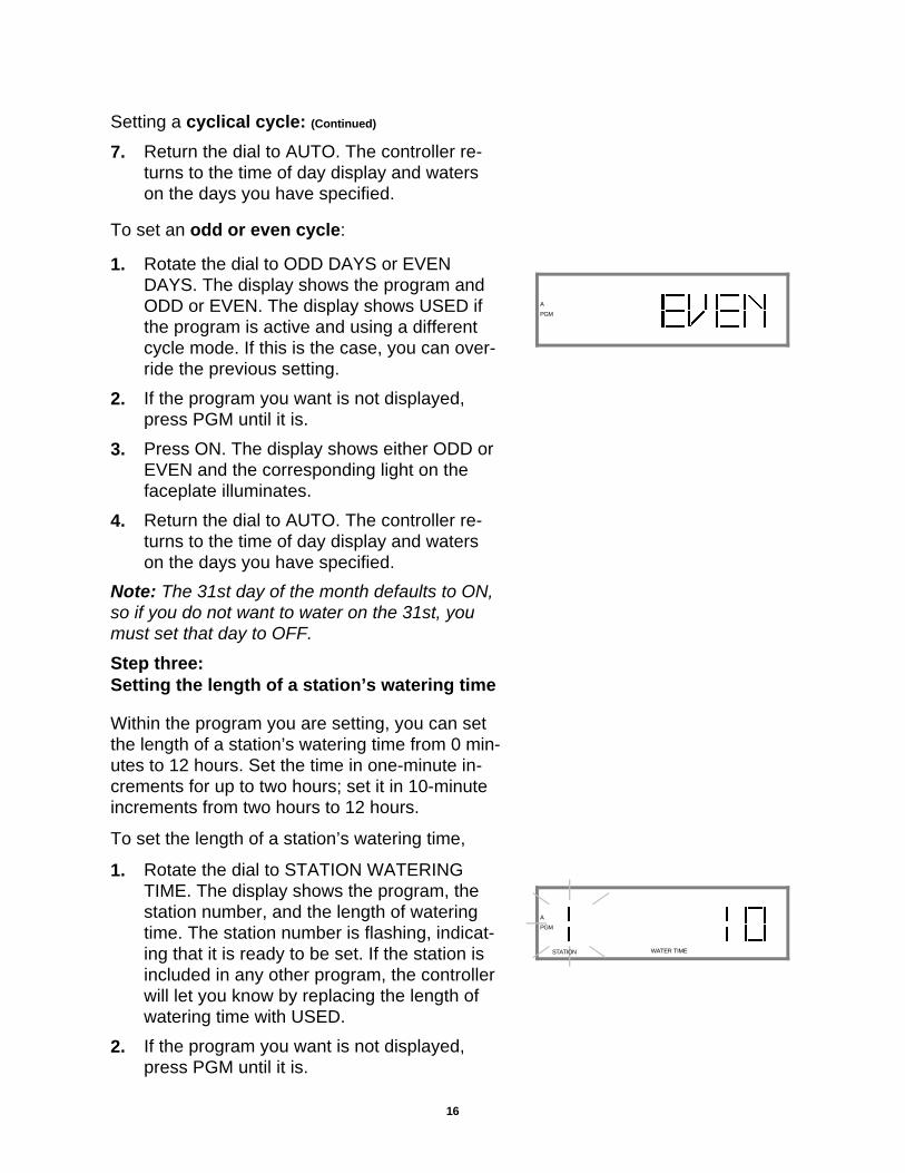
To set an odd or even cycle:
1. Rotate the dial to ODD DAYS or EVENDAYS. The display shows the program andODD or EVEN. The display shows USED ifthe program is active and using a differentcycle mode. If this is the case, you can over-ride the previous setting.
2. If the program you want is not displayed,press PGM until it is.
3. Press ON. The display shows either ODD orEVEN and the corresponding light on thefaceplate illuminates.
4. Return the dial to AUTO. The controller re-turns to the time of day display and waterson the days you have specified.
Note: The 31st day of the month defaults to ON,so if you do not want to water on the 31st, youmust set that day to OFF.
Step three:Setting the length of a station’s watering time
Within the program you are setting, you can setthe length of a station’s watering time from 0 min-utes to 12 hours. Set the time in one-minute in-crements for up to two hours; set it in 10-minuteincrements from two hours to 12 hours.
To set the length of a station’s watering time,
1. Rotate the dial to STATION WATERINGTIME. The display shows the program, thestation number, and the length of wateringtime. The station number is flashing, indicat-ing that it is ready to be set. If the station isincluded in any other program, the controllerwill let you know by replacing the length ofwatering time with USED.
2. If the program you want is not displayed,press PGM until it is.
PGM
A
PGM
A
STATION WATER TIME

17
3. Use the arrow keys to display the stationnumber you wish to set.
4. Press MAN START/ADV to toggle to the rightside of the display. The length of wateringtime flashes, indicating that it is ready to beset.
5. Use the arrow keys to set the length of time.If USED is displayed, you can still set thelength of time. (You can include the samestation in different programs and give thatstation different lengths of watering time.)
6. Return the dial to AUTO. The display showsto the time of day.
Step four: Setting watering start times
For each program, you may assign up to eightstart times per day, available on the quarter hour.To do so:
1. Rotate the dial to WATERING START TIME.The display shows the program, the numberof the start time, and the start time. The num-ber of the start time is flashing, indicatingthat it is ready to be set.
2. If the program you want is not displayed,press PGM until it is.
3. Use the arrow keys to select one of the eightstart times.
4. Press MAN START/ADV to toggle to the rightside of the display. The start time flashes, in-dicating that it is ready to be set.
5. Use the arrow keys to select a start time.Start times are available in fifteen minute in-tervals, with an OFF setting available be-tween the 11:45 pm and 12:00 am options onthe 60 Hz model (and between 23:45 and24:00 on the 50 Hz model).
PGM
A AM

18
Note: Start times are displayed in chronologicalorder. If a start time is deleted from the order bysetting it to OFF, all later start times are automati-cally moved down one start time number. Whena start time is added to any start time number,the controller automatically reorganizes the timesso that times appear in chronological order. Thisreorganizing only occurs after the dial has beenmoved off the WATERING START TIMES posi-tion.
6. If you want to set additional start times, pressMAN START/ADV to toggle back to the leftside of the display and the next availablestart time number. Set the next start time inthe same fashion as the first.
7. Return the dial to AUTO. The controller re-turns to the time of day.
Step five:Setting programs to stack or overlap
You can set a program to stack (run one at atime) or overlap (run simultaneously). The ESP-MC can run up to nine valves simultaneously.The default setting is to stack all programs. Toset programs to stack or overlap:
1. Rotate the dial to PROGRAM OVERLAP.The display shows the program, and STACKor OVERLAP.
2. If the program you want is not displayed,press PGM until it is.
3. Use the arrow keys to set the program to ei-ther STACK or OVERLAP.
4. Return the dial to AUTO. The controller re-turns to the time of day display.
Step six: Setting the MV/PUMP start
The ESP-MC has two master valve terminals onits circuit board. MV2 (master valve 2) is enabledwhen any station operates. MV1 (master valve 1)can be enabled or disabled for each individualstation.
PGM
A
19
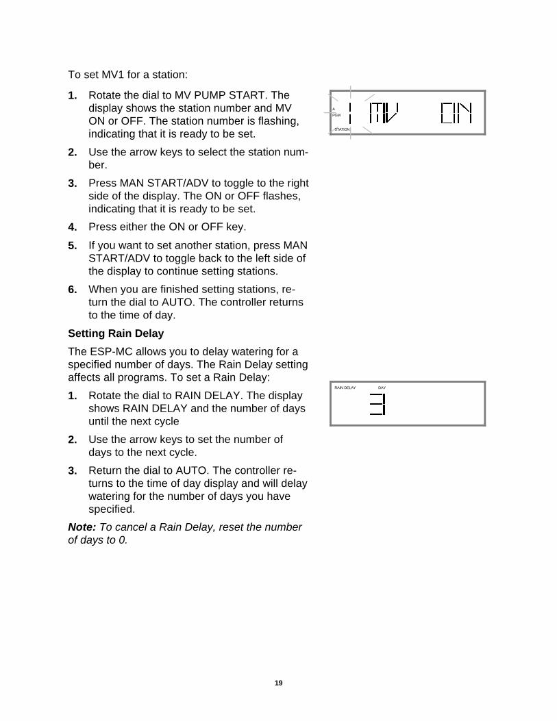
To set MV1 for a station:
1. Rotate the dial to MV PUMP START. Thedisplay shows the station number and MVON or OFF. The station number is flashing,indicating that it is ready to be set.
2. Use the arrow keys to select the station num-ber.
3. Press MAN START/ADV to toggle to the rightside of the display. The ON or OFF flashes,indicating that it is ready to be set.
4. Press either the ON or OFF key.
5. If you want to set another station, press MANSTART/ADV to toggle back to the left side ofthe display to continue setting stations.
6. When you are finished setting stations, re-turn the dial to AUTO. The controller returnsto the time of day.
Setting Rain Delay
The ESP-MC allows you to delay watering for aspecified number of days. The Rain Delay settingaffects all programs. To set a Rain Delay:
1. Rotate the dial to RAIN DELAY. The displayshows RAIN DELAY and the number of daysuntil the next cycle
2. Use the arrow keys to set the number ofdays to the next cycle.
3. Return the dial to AUTO. The controller re-turns to the time of day display and will delaywatering for the number of days you havespecified.
Note: To cancel a Rain Delay, reset the numberof days to 0.
PGM
A
STATION
DAYRAIN DELAY

20
Setting Cycle + Soak
The Cycle + Soak feature is designed to con-serve water that might puddle in tight soils suchas clay, or end up as runoff on slopes. Cycle +Soak lets you break up the total watering time ofa station into shorter cycles with a soak time be-tween cycles. You set the maximum wateringtime length and the minimum soak time. Thissetting affects all programs in which the station isincluded.
For example, if you want to water a station for atotal of 20 minutes, but runoff begins to occur af-ter 5 minutes, you can set the station for 5-minute maximum cycles, and a minimum of 25minutes between cycles. While the station is insoak mode, the controller operates other stationsin the program.
Note: If there is nothing left for the controller todo but wait until a soak time elapses, the displayshows SOAK.
Note: The Test program does not respond to Cy-cle and Soak settings.
To set Cycle + Soak:
1. Rotate the dial to CYCLE + SOAK. The dis-play shows the station number, the length oftime to water, and the length of time to soak.The station number is flashing, indicatingthat it is ready to be set.
2. Use the arrow keys to select the station.
3. Press MAN START/ADV. The length of timeto water flashes, indicating that it is ready tobe set.
4. Use the arrow keys to set the maximumlength of time to water from 1 to 60 minutes.
5. Press MAN START/ADV. The length of timeto soak flashes, indicating that it is ready tobe set.
6. Use the arrow keys to set the minimumlength of time to soak for from 1 to 60 min-utes.
STATION WATER TIME
STATION WATER TIME

21
7. If you want to set Cycle and Soak for anotherstation, press MAN START/ ADV again.
8. When you have finished setting Cycle andSoak, return the dial to AUTO. The controllerreturns to the time of day.
Setting the Water Budget
The water budget feature allows you to increaseor decrease a program’s watering time in incre-ments of 1% without having to reset the timing foreach station in the program. You can set thebudget for 0% to 300%. You can use the 0% set-ting to shut a program down temporarily. To setthe water budget:
1. Rotate the dial to WATER BUDGET. Thedisplay shows the program and the waterbudget percentage.
2. Press PGM until the program you want isdisplayed.
3. Use the arrow keys to set the percentage.
4. Return the dial to AUTO. The controller re-turns to the time of day display. The defaultpercentage for all programs is 100%. Whenthe water budget for a program is set to otherthan 100%, WATER BUDGET will show inthe display whenever that program is se-lected.
Setting Event Day Off
The Event Day Off feature allows you to omittemporarily a calendar day or days from the wa-tering cycle. After a calendar day passes, thatday returns to the default setting. The default forall days is ON. If the 31st is set to OFF, it re-mains off until it is set to ON. This is to accom-modate odd day watering cycles which do not al-low watering on the 31st and 1st. To set a dayoff:
1. Rotate the dial to EVENT DAY OFF. The dis-play shows the day of the month on the left,and the ON or the OFF setting on the right.The day of the month is flashing, indicatingthat it is ready to be set.
PGM
A
WATER BUDGET PERCENT
DAY

22
2. Use the arrow keys to set the day of themonth you wish to change.
3. Press MAN START/ADV to toggle to the rightside of the display. The ON/OFF settingflashes, indicating that it is ready to be set.
4. If you are setting the day to on press ON; ifyou are setting the day to off, press OFF.
5. Return the dial to AUTO. When a day off ar-rives, the display shows NON (for non-watering day) and the controller does not al-low watering.
Operating the ControllerOnce you have programmed the ESP-MC, oper-ating the controller is easy. You may choose tooperate it completely automatically or to operateit manually from time to time. When you operatethe ESP-MC manually, you do not disturb any ofthe programmed instructions.
Operating Automatically
To operate the controller automatically:
1. Rotate the dial to AUTO. The controller runseach of the programs as you have specified.
Operating Manually
There are a number of functions you can performmanually. Each one is described in this section.
Operating a program or programs manually
You can select, start, and manually advance pro-grams for semi-automatic operation. To do so,
1. Rotate the dial to AUTO. The display showsthe day of the week and the time of day.
2. Press PGM until the program you wish to op-erate is displayed.
3. Press MAN START/ADV to start the selectedprogram. You must press MAN START/ADVbefore PGM disappears.
DAY
PM

23
4. If you want to operate more than one pro-gram, press PGM to select another programand press MAN START/ADV again. The sec-ond program runs when the first is complete.You can stack all four programs in this way.
Operating a station or stations manually
You can initiate one-time operation of a singlestation or a combination of stations. If you runmore than one station, they will run in the orderin which they were selected. To operate one sta-tion or multiple stations:
1. Rotate the dial to MANUAL WATER. Thedisplay shows the program, the station num-ber, and any watering time remaining on thatstation.
2. Press PGM until the program you want isdisplayed.
3. Use the arrow keys to select the station youwant to operate.
4. Press MAN START/ADV to start the selectedstation.
5. If you want to operate more than one station,repeat steps 2 through 4.
6. Return the dial to AUTO. The controller re-turns to the time of day display and the sta-tions operate in the sequence they were se-lected. After the stations are finished water-ing, the controller returns to the automaticmode.
Note: When you operate a station manually, youcannot change the amount of time the station willwater. You must water for the amount of time al-ready programmed.
PGM
A
WATER TIME REMAININGSTATION

24
Using the test program
The test program allows you to run a test cyclefor all the stations on a particular program. It alsolets you decide how long the test will last.To setand then start a test program:
1. Rotate the dial to TEST PROGRAM. The dis-play shows the program, TEST, and thelength of time to test.
2. Press PGM until the program you want totest is displayed.
3. Use the arrow keys to set the length of timeto test each station for from 1 to 99 minutes.
4. Press MAN START/ADV to start the test.The test time flashes and the controller runsthe test program immediately, suspendingany work in progress.
5. If you want to add other programs to the test,with the dial set to TEST PROGRAM, pressPGM to select the program. Then press MANSTART/ADV to stack the new program afterthe first one. You can stack four programs.
Note: To cancel the test on all programs, rotatethe dial to OFF.
6. Rotate the dial back to AUTO to return tonormal programming and operation.
Using the Sensor Option
The ESP-MC allows you to connect a sensor thatcan disable watering. When a sensor is con-nected to the ESP-MC and it suspends watering,the sensor light on the front panel illuminates. Toenable the sensor:
1. Set the sensor switch to ACTIVE. The con-troller operates as usual until the sensor sus-pends watering and the controller displayshows SUSPENDED BY SENSOR.
PGM
A

25
Using the Diagnostic Circuit Breaker
The ESP-MC is equipped with a circuit overload protection system. This systemcauses the controller to skip over a station that has an electrical short circuit, ratherthan blow a fuse which would shut down the entire system.
When the controller tries to start a station that has a short circuit, the electronic circuitbreaker senses the short circuit and skips that station. The controller skips to the nextstation, but flashes the skipped station number and FAULT in the display.
Once you have corrected the problem, push the FAULT RESET button to clear theflashing fault indicator.
Note: The diagnostic circuit breaker allows detection on all valves, including the mas-ter valve.
Appendix
Scheduling Chart
Before you begin programming, it is a good idea to chart your watering schedule, tak-ing into account the schedule for all stations and how often you want to repeat theschedule. A sample schedule appears below.

26
Glossary
Circuit boardOne of the etched, copper clad sheets of insulating material onto which electroniccomponents and terminals are assembled. Controllers contain circuit boards.
ControllerA device that sends a 24 VAC power signal to the field solenoid valves.
CPU boardThe central processing unit circuit board inside the controller.
Default settingThe start-up settings for the controller. The default settings cannot be changed.
ESP-MCExtra Simple Programming — MAXICOM Compatible series, an 8, 12, 16, 24, 32, or40 independent station controller that is a stand-alone unit, but is upgradable to asatellite controller linked to MAXICOM.
GPMGallons per minute.
HardwireCommunication cable used to transmit data between devices.
Liquid crystal display (LCD)The illuminated display used on the faceplate of most controllers.
ManualRequires user input, rather than being automatically performed by the PC program.
Master valve (MV)An electrically operated valve located on a system’s main line that controls the flow ofwater to all other electric and manual valves downstream of it.
Master valve circuitAn electrical circuit located on many controllers used to control a master valve. Re-gardless of what station is on at the controller, the master valve circuit produces volt-age to control the master valve. When all of the stations on the controller are off, themaster valve circuit turns off.
MonitorTo observe conditions in and around the irrigation system and send the information tothe different components in the system for appropriate action.
SatelliteA controller in the field capable of communicating with the Cluster Control Unit (CCU).
Satellite controllerSame as satellite.
Sensor systemAn optional addition to the controller that disables watering. Examples are the RainBird Aquamiser, Intellisense, Rain Check, and Rain/Freeze Check.
SiteA single, remote irrigated area controlled by a CCU. For example, one park is a site in
27
Soil infiltration rateThe rate at which soils accept water.
SolenoidA portion of a field valve that receives a 24 VAC electrical current from the controller.
Station scheduleThe watering schedule for one of the stations controlled by the controller.
ValveA manual or electrically operated device used to control flow of water in an irrigationsystem.
Water budgetA feature available in some controllers and central control systems allowing adjust-ment of water application times without reprogramming each station or irrigationschedule.
Watering cycle
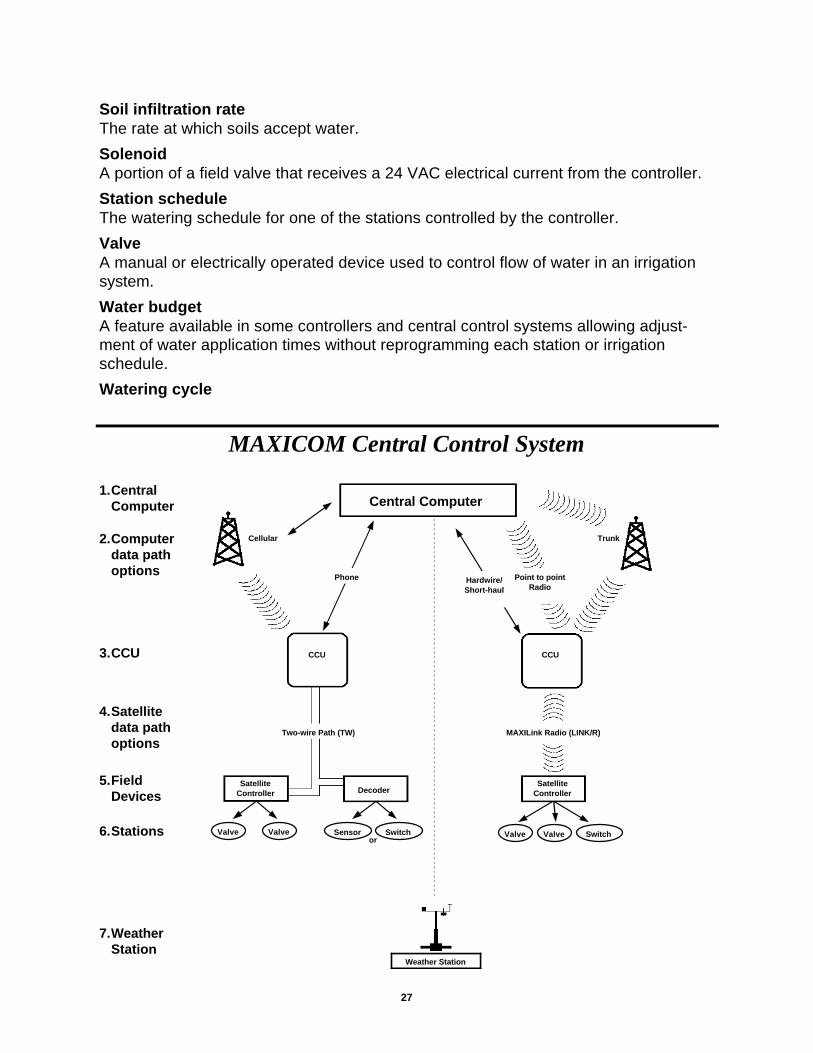
Central Computer
Cellular
CCU
Phone
SatelliteController Decoder
Two-wire Path (TW)
ValveValve Sensor Switchor
Hardwire/Short-haul
Point to pointRadio
Trunk
CCU
MAXILink Radio (LINK/R)
SatelliteController
SwitchValveValve
Weather Station
MAXICOM Central Control System
1.CentralComputer
2.Computerdata pathoptions
3.CCU
4.Satellitedata pathoptions
5.FieldDevices
6.Stations
7.WeatherStation

28
Service Information
In the unlikely event this equipment should malfunction, all repairs should be per-formed by an authorized Rain Bird MAXICOM Authorized Service Center.
For information on MAXICOM Authorized Service Centers, contact Rain Bird at:
BBIRDIRDRRAINAINPREFERRED BY PROFESSIONALS WORLDWIDE
Rain Bird Sales, Inc.Customer Support Center
6640 S. Bonney Ave.Tucson, AZ 857061-800-RAIN BIRD
(520) 434-6289 FAX