Embed Size (px)
Citation preview

MMG-H IE450 Hz
Installation and operating instructions
GRUNDFOS INSTRUCTIONS


MMG-H IE4
English (GB)Installation and operating instructions . . . . . . . . . . . . . . . . . . . . . . . . . . . . . . . . . .4
3
Tabl
e of
con
tent
s
English (GB) Installation and operating instructions
Original installation and operating instructions
Table of contents1. General information . . . . . . . . . . . . . 41.1 Hazard statements . . . . . . . . . . . . . . 41.2 Notes . . . . . . . . . . . . . . . . . . . . . 4
2. Product introduction . . . . . . . . . . . . 52.1 Product description . . . . . . . . . . . . . . 52.2 Standards and specifications . . . . . . . . . 5
3. General safety warnings . . . . . . . . . . 7
4. Receiving the product. . . . . . . . . . . . 7
5. Mechanical installation . . . . . . . . . . . 85.1 Lifting the product . . . . . . . . . . . . . . . 85.2 Assembling the connecting device . . . . . . 85.3 Direct connection . . . . . . . . . . . . . . . 85.4 Connection by means of pulley. . . . . . . . 85.5 Connecting to the power supply . . . . . . . 85.6 Connection of auxiliary parts . . . . . . . . . 85.7 Fixing to the base . . . . . . . . . . . . . . . 9
6. Electrical connection . . . . . . . . . . . . 106.1 Wiring diagrams. . . . . . . . . . . . . . . . 10
7. Startup . . . . . . . . . . . . . . . . . . . . 117.1 Initial controls . . . . . . . . . . . . . . . . . 117.2 Control of design data . . . . . . . . . . . . 117.3 Starting . . . . . . . . . . . . . . . . . . . . 127.4 Conditions of use . . . . . . . . . . . . . . . 12
8. Service . . . . . . . . . . . . . . . . . . . . 138.1 Checking . . . . . . . . . . . . . . . . . . . 138.2 Lubrication . . . . . . . . . . . . . . . . . . 138.3 Dismantling and reassembling . . . . . . . . 148.4 Bearing replacement . . . . . . . . . . . . . 148.5 Repairs and overhauls . . . . . . . . . . . . 15
9. Storage . . . . . . . . . . . . . . . . . . . . 159.1 Storage conditions . . . . . . . . . . . . . . 159.2 Checking the bearings . . . . . . . . . . . . 159.3 Checking the insulation . . . . . . . . . . . . 15
10. Fault finding the product . . . . . . . . . . 1610.1 The motor does not start . . . . . . . . . . . 1610.2 The motor does not reach its nominal
speed or the acceleration times are toolong and/or absorption excessive . . . . . . 16
10.3 The motor overheats when working underload . . . . . . . . . . . . . . . . . . . . . . 16
10.4 Incorrect rotation . . . . . . . . . . . . . . . 1710.5 Functioning of the protective device . . . . . 1710.6 Abnormal vibrations. . . . . . . . . . . . . . 1710.7 Irregular noise. . . . . . . . . . . . . . . . . 18
10.8 Bearings overheating . . . . . . . . . . . . . 18
11. Disposing of the product . . . . . . . . . . 18
1. General informationRead this document before you install theproduct. Installation and operation mustcomply with local regulations and acceptedcodes of good practice.
1.1 Hazard statementsThe symbols and hazard statements below mayappear in Grundfos installation and operatinginstructions, safety instructions and serviceinstructions.
DANGERIndicates a hazardous situation which, ifnot avoided, will result in death or seriouspersonal injury.
WARNINGIndicates a hazardous situation which, ifnot avoided, could result in death orserious personal injury.
CAUTIONIndicates a hazardous situation which, ifnot avoided, could result in minor ormoderate personal injury.
The hazard statements are structured in the followingway:
SIGNAL WORDDescription of the hazardConsequence of ignoring the warning• Action to avoid the hazard.
1.2 NotesThe symbols and notes below may appear inGrundfos installation and operating instructions,safety instructions and service instructions.
Observe these instructions for explosion-proof products.
A blue or grey circle with a white graphicalsymbol indicates that an action must betaken.
4
English (GB)

A red or grey circle with a diagonal bar,possibly with a black graphical symbol,indicates that an action must not be takenor must be stopped.
If these instructions are not observed, itmay result in malfunction or damage to theequipment.
Tips and advice that make the work easier.
2. Product introduction
2.1 Product descriptionThe electrical machines mentioned in theseinstructions are intended as components for use inindustrial areas. The information contained in thisdocumentation is designed for use by qualifiedpersons who are familiar with the current rules andregulations in force. They are not intended to replaceany installation regulations issued for safetypurposes. Low voltage motors are to be consideredas components to be installed on machines.Commissioning is forbidden until the final product hasbeen checked for conformity.
This manual applies to all the standard series ofMMG-H and various series of motors derived from it.Frame size: 56-355. (For some special designedtypes of motors or those for special applications, itneeds to refer to other special instructions.)
2.1.1 Electromagnetic compatibilityLow voltage induction motors, if installed correctlyand connected to the power supply, respect allimmunity and emission limits as set out in theregulations relating to electromagnetic compatibility(EMC generic standard for industrial environments).In the case of supply by means of electronic impulse(inverters, soft starters, etc.), all verifications and anymodifications necessary to ensure that emission andimmunity limits stated within the regulations arerespected, are the responsibility of the installer.
2.1.2 Motors for classified areasMotors to be used in dangerous areas are designedin compliance with European standards, usingprotection methods that are suitable for guaranteeingsafety in areas subject to risk of fire and explosion.Where these motors are used improperly or modified,their safety may be impaired.
2.2 Standards and specifications
TitleInternationa
lIEC
EUCENELEC
ICEI-EN
GBBS
FNFC
DDIN/VDE
Electrical rotatingmachines/ratedoperation andcharacteristic data
IEC 60034-1 EN 60034-1CEI-EN
60034-1 (CEI2-3)
BS 4999-1BS 4999-69
NFC51-100NFC 51-111 VDE 0530-1
Methods fordetermining lossesand efficiency ofrotating electricalmachinery
IEC 60034-2 EN 60034-2CEI-EN
60034-2 (CEI2-6)
BS 4999-34 NFC 51-112 VDE 0530-2
Protection types ofrotating electricalmachines
IEC 60034-5 EN 60034-5CEI-EN
60034-5 (CEI2-16)
BS 4999-20 NFC 51-115 VDE 0530-5
Cooling methods ofrotating electricalmachines
IEC 60034-6 EN 60034-6CEI-EN
60034-6 (CEI2-7)
BS 4999-21 IEC 34-6 DIN IEC 34-6
Construction typesof rotating electricalmachines
IEC 60034-7 EN 60034-7CEI-EN
60034-7 (CEI2-14)
BS 4999-22 NFC 51-117 DIN IEC 34-7
5
Engl
ish
(GB)

TitleInternationa
lIEC
EUCENELEC
ICEI-EN
GBBS
FNFC
DDIN/VDE
Terminal markingsand direction ofrotation for electricalmachines
IEC 60034-8 EN 60034-8 CEI 2-8 BS 4999-3 NFC 51-118 VDE 0530-8
Noise emission, limitvalues IEC 60034-9 EN 60034-9
CEI-EN50034-9 (CEI
2-24)BS 4999-51 NFC 51-119 VDE 0530-9
Start-up behaviour ofsquirrel-cage motorsat 50 Hz up to 660 V
IEC60034-12 EN 60034-12
CEI-EN60034-12(CEI 2-15)
BS 4999-112 IEC 34-12 VDE 0530-12
Vibration severity ofrotating electricalmachines
IEC60034-14 EN 60034-14
CEI EN60034-14(CEI 2-23)
BS 4999-50 NFC 51-111 DIN ISO2373
Fixing dimensionsand output for IM B3 IEC 60072 EN 50347 IEC 60072 BS 4999-10 NFC 51-
104/110 DIN 42673
Fixing dimensionsand output for IM B5,IM B14
IEC 60072 EN 50347 IEC 60072 BS 4999-10 NFC 51-104/110 DIN 42677
Cylindrical shaftends for electricalmachines
IEC 60072 EN 50347 IEC 60072 BS 4999-10 NFC 51-111 DIN 748-3
Electrical equipmentfor hazardous areaGeneral Provisions
IEC 60079-0 EN 60079-0 (CEI 31-8) BS 5501-1 NFC 23-514 VDE 0171-1
Electrical equipmentfor hazardous areaFlame-proofenclosure "d"
IEC 60079-1 EN 60079-1 (CEI 31-1) BS 5501-5 NFC 23-518 VDE 0171-5
Electrical equipmentfor hazardous areaIncreased safety "e"
IEC 60079-7 EN 60079-7 (CEI 31-7) BS 5501-6 NFC 23-519 VDE 0171-6
Checking andmaintenance atelectrical systems inplaces in danger ofexplosion due to thepresence of gas
IEC60079-17 EN 60079-17 CEI EN
60079-17 --- --- ---
Electrical systems inplaces in danger ofexplosion due to thepresence of gas
IEC60079-14
IEC60079-14
IEC60079-14 --- --- ---
6
English (GB)
TitleInternationa
lIEC
EUCENELEC
ICEI-EN
GBBS
FNFC
DDIN/VDE
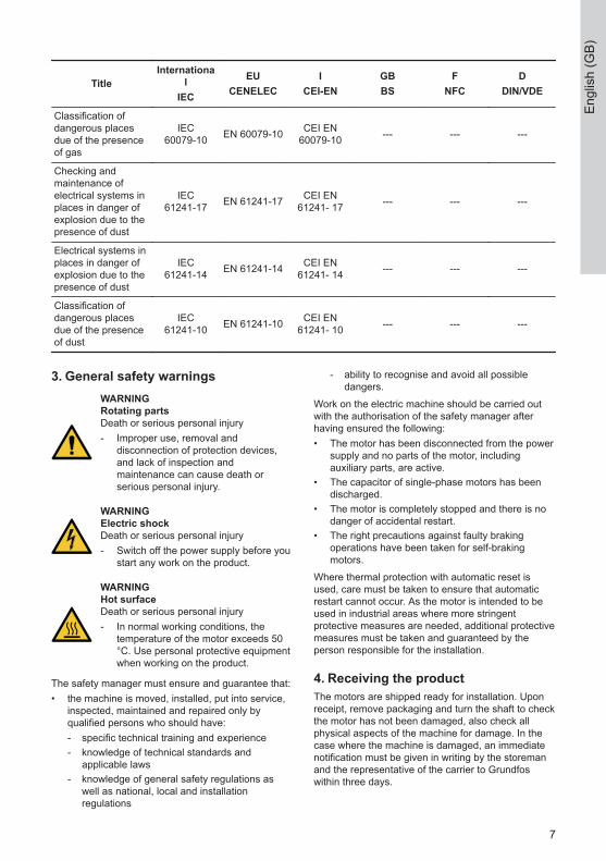
Classification ofdangerous placesdue of the presenceof gas
IEC60079-10 EN 60079-10 CEI EN
60079-10 --- --- ---
Checking andmaintenance ofelectrical systems inplaces in danger ofexplosion due to thepresence of dust
IEC61241-17 EN 61241-17 CEI EN
61241- 17 --- --- ---
Electrical systems inplaces in danger ofexplosion due to thepresence of dust
IEC61241-14 EN 61241-14 CEI EN
61241- 14 --- --- ---
Classification ofdangerous placesdue of the presenceof dust
IEC61241-10 EN 61241-10 CEI EN
61241- 10 --- --- ---
3. General safety warningsWARNINGRotating partsDeath or serious personal injury‐ Improper use, removal and
disconnection of protection devices,and lack of inspection andmaintenance can cause death orserious personal injury.
WARNINGElectric shockDeath or serious personal injury‐ Switch off the power supply before you
start any work on the product.
WARNINGHot surfaceDeath or serious personal injury‐ In normal working conditions, the
temperature of the motor exceeds 50°C. Use personal protective equipmentwhen working on the product.
The safety manager must ensure and guarantee that:• the machine is moved, installed, put into service,
inspected, maintained and repaired only byqualified persons who should have:- specific technical training and experience- knowledge of technical standards and
applicable laws- knowledge of general safety regulations as
well as national, local and installationregulations
- ability to recognise and avoid all possibledangers.
Work on the electric machine should be carried outwith the authorisation of the safety manager afterhaving ensured the following:• The motor has been disconnected from the power
supply and no parts of the motor, includingauxiliary parts, are active.
• The capacitor of single-phase motors has beendischarged.
• The motor is completely stopped and there is nodanger of accidental restart.
• The right precautions against faulty brakingoperations have been taken for self-brakingmotors.
Where thermal protection with automatic reset isused, care must be taken to ensure that automaticrestart cannot occur. As the motor is intended to beused in industrial areas where more stringentprotective measures are needed, additional protectivemeasures must be taken and guaranteed by theperson responsible for the installation.
4. Receiving the productThe motors are shipped ready for installation. Uponreceipt, remove packaging and turn the shaft to checkthe motor has not been damaged, also check allphysical aspects of the machine for damage. In thecase where the machine is damaged, an immediatenotification must be given in writing by the storemanand the representative of the carrier to Grundfoswithin three days.
7
Engl
ish
(GB)

5. Mechanical installationWork on the electric machine must becarried out when the machine has stoppedand been disconnected from the powersupply (including auxiliary parts, such asanticondensation heaters).
5.1 Lifting the product
Before using the lifting rings, make surethey have been tightened.
The lifting rings are big enough to bear theweight of a single motor, therefore theymust not be used to lift the equipmentconnected to the motor.
In environments where the temperature isbelow -20 °C, these lifting rings should beused with caution as they could break atlow temperatures and cause damage.
5.2 Assembling the connecting device
Fitting pulley, coupling or gear to the motorshaft must be carried out with care toensure no damage is caused to thebearing.
Fitments not balanced properly can causeanomalous vibrations during operation thatjeopardizes the proper working of themotor and drastically reduces its life.
1. Remove the protective paint finish from the shaftand smear with oil.
2. Fit the device, heating before fitting, if possible, toensure an easy fit.
Any component that is assembled on the motor shaftmust be accurately balanced. The motor is normallybalanced using a half key and the letter H is punchedon the shaft.
5.3 Direct connectionUse couplings that have been made and balancedperfectly to align the motor shaft and the operatingmachine precisely.
Inaccurate alignment may cause vibrationsand damage to the bearings or breakageof the shaft end.
5.4 Connection by means of pulleyCheck that alignment with the pulley of the operatingmachine has been carried out perfectly. The tensionof the belts must be enough to avoid slipping.
Excessive tension of the belts causes harmful radialloads on the motor shaft and bearings, reducing theirlife.
Excessive tension of the belts causesharmful radial loads on the motor shaft andbearings, reducing their life.
We recommend assembling the motor onbelt-tensioning slides in order to accuratelyadjust the tension of the belts.
A connection with belts must be such as to avoidaccumulation of static charges in the moving beltswhich could cause sparks.
5.5 Connecting to the power supply
Use cables with sufficient section to bearthe maximum current absorbed by themotor, avoiding overheating and/or dropsin voltage.
Connections to the terminals must bemade in order to guarantee safe distancesbetween live uncovered parts.
Earthing is through the screw locatedinside the terminal box. Earths must be ofsufficient size and installed according torelevant standards. The area of contact ofconnections must be cleaned andprotected against corrosion.
When the cable inlet is made by means ofa cable gland, it must be chosen properlyin relation to the type of equipment andtype of cable used. The cable gland mustbe tightened so that the retaining ringscreate the pressure necessary to:• prevent transmission of mechanical
stress to the motor terminals• ensure the mechanical (IP degree)
protection of the terminal box.
1. Connect the cables to terminals by following theinstructions on the nameplate or on the diagramincluded in the terminal box.
2. Make sure that the terminal nuts are tightened.
5.6 Connection of auxiliary parts
Thermal protectionCheck which type of protection is installed beforemaking connections. If thermistors (PTC) are used, itis necessary to utilise a suitable relay.
8
English (GB)

Do not apply a tension over 6 V during thethermistor continuity test.
AnticondensationIf the motor is fitted with anticondensation heaters,their power supply must be separated from that of themotor, using the terminals housed in the terminal box.
The supply of the heater is always mono-phase and the voltage is different from thatof the motor. Check that it corresponds tothe one indicated on the nameplate.
Auxiliary ventilationConnect the supply of the auxiliary ventilation motorseparately from that of the main motor.
Use a device that allows starting andoperation of the main motor only when theauxiliary fan is working.
5.7 Fixing to the baseThe bolts fixing the motor to the base must be fittedwith washers to ensure adequate load distribution.
9
Engl
ish
(GB)
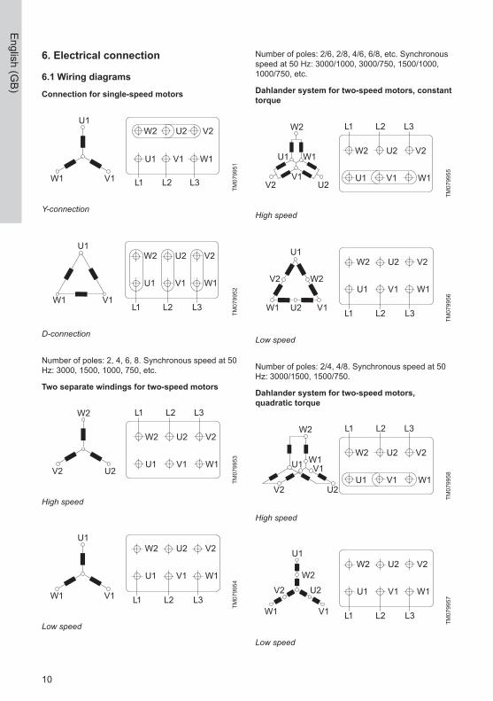
6. Electrical connection
6.1 Wiring diagrams
Connection for single-speed motors
U1
W1 V1
W2
U1 V1 W1
L1 L2 L3
U2 V2
TM07
9951
Y-connection
U1
W1 V1
W2
U1 V1 W1
L1 L2 L3
U2 V2
TM07
9952
D-connection
Number of poles: 2, 4, 6, 8. Synchronous speed at 50Hz: 3000, 1500, 1000, 750, etc.
Two separate windings for two-speed motors
W2
V2 U2
W2
U1 V1 W1
L1 L2 L3
U2 V2
TM07
9953
High speed
U1
W1 V1
W2
U1 V1 W1
L1 L2 L3
U2 V2
TM07
9954
Low speed
Number of poles: 2/6, 2/8, 4/6, 6/8, etc. Synchronousspeed at 50 Hz: 3000/1000, 3000/750, 1500/1000,1000/750, etc.
Dahlander system for two-speed motors, constanttorque
W2
V1
U1 W1
V2 U2
W2
U1 V1 W1
L1 L2 L3
U2 V2
TM07
9955
High speed
U1
U2
W2V2
W1 V1
W2
U1 V1 W1
L1 L2 L3
U2 V2
TM07
9956
Low speed
Number of poles: 2/4, 4/8. Synchronous speed at 50Hz: 3000/1500, 1500/750.
Dahlander system for two-speed motors,quadratic torque
W2
U1 V1 W1
L1 L2 L3
U2 V2
W2
V1U1 W1
V2 U2
TM07
9958
High speed
U2
W2
V2
W2
U1 V1 W1
L1 L2 L3
U2 V2U1
W1 V1
TM07
9957
Low speed
10
English (GB)
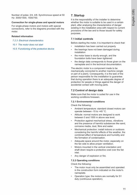
Number of poles: 2/4, 4/8. Synchronous speed at 50Hz: 3000/1500, 1500/750.
Connection for single-phase and special motorsFor single-phase motors and motors with specialconnections, refer to the diagrams provided with themotor.
Related information
7.2.3 Electrical characteristics
10.1 The motor does not start
10.5 Functioning of the protective device
7. StartupIt is the responsibility of the installer to determinewhether the motor is suitable to be used in a certainplant, after analysing the characteristics of dangerexisting in the installation area with respect to currentprovisions of the law and to those issued for safetypurposes.
7.1 Initial controlsBefore starting the motor, it is important to check that:• installation has been carried out properly• the bearings have not been damaged during
installation• the motor base is sturdy enough, and the
foundation bolts have been tightened• the design data corresponds to those given on the
nameplate and in the technical documentation.The electric motor is a component made to bemechanically connected to another machine (singleor part of a plant). Consequently, it is the task of theperson responsible for the installation to guaranteethat during operation there is an adequate degree ofprotection for people or things against the danger ofaccidental contact with moving parts.
7.2 Control of design dataMake sure that the motor is suited for use in theworking conditions foreseen.
7.2.1 Environmental conditionsCheck the following:• Ambient temperature: standard closed motors can
operate between -15 to +40 °C.• Altitude: normal motors are designed to work
between 0 and 1000 m above sea level.• Protection against mechanical stress, vibrations
and the presence of harmful substances like sand,corrosive media, dust, fibre and water.
• Mechanical protection: install indoors or outdoorsconsidering the harmful effects of the weather, thecombined effect of temperature and humidity andthe formation of condensation.
• Adequate space around the motor, especially onthe fan side to allow proper ventilation.
• Motors mounted in the vertical orientation andshaft down require a protective cowl over the faninlet.
• Any danger of explosion or fire.
7.2.2 Operating conditionsCheck the following:• The motor must only be assembled and operated
in the construction form indicated on the motor'snameplate.
• Operation type: the motors are normally for S1duty (continuous operation).
11
Engl
ish
(GB)
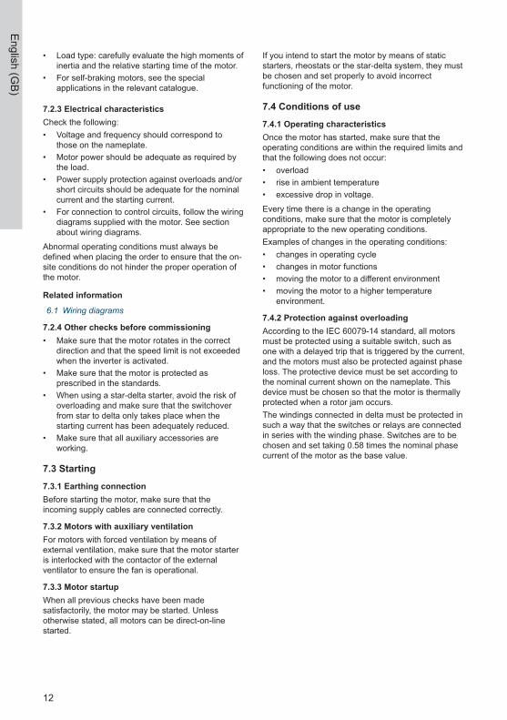
• Load type: carefully evaluate the high moments ofinertia and the relative starting time of the motor.
• For self-braking motors, see the specialapplications in the relevant catalogue.
7.2.3 Electrical characteristicsCheck the following:• Voltage and frequency should correspond to
those on the nameplate.• Motor power should be adequate as required by
the load.• Power supply protection against overloads and/or
short circuits should be adequate for the nominalcurrent and the starting current.
• For connection to control circuits, follow the wiringdiagrams supplied with the motor. See sectionabout wiring diagrams.
Abnormal operating conditions must always bedefined when placing the order to ensure that the on-site conditions do not hinder the proper operation ofthe motor.
Related information
6.1 Wiring diagrams
7.2.4 Other checks before commissioning• Make sure that the motor rotates in the correct
direction and that the speed limit is not exceededwhen the inverter is activated.
• Make sure that the motor is protected asprescribed in the standards.
• When using a star-delta starter, avoid the risk ofoverloading and make sure that the switchoverfrom star to delta only takes place when thestarting current has been adequately reduced.
• Make sure that all auxiliary accessories areworking.
7.3 Starting7.3.1 Earthing connectionBefore starting the motor, make sure that theincoming supply cables are connected correctly.
7.3.2 Motors with auxiliary ventilationFor motors with forced ventilation by means ofexternal ventilation, make sure that the motor starteris interlocked with the contactor of the externalventilator to ensure the fan is operational.
7.3.3 Motor startupWhen all previous checks have been madesatisfactorily, the motor may be started. Unlessotherwise stated, all motors can be direct-on-linestarted.
If you intend to start the motor by means of staticstarters, rheostats or the star-delta system, they mustbe chosen and set properly to avoid incorrectfunctioning of the motor.
7.4 Conditions of use7.4.1 Operating characteristicsOnce the motor has started, make sure that theoperating conditions are within the required limits andthat the following does not occur:• overload• rise in ambient temperature• excessive drop in voltage.Every time there is a change in the operatingconditions, make sure that the motor is completelyappropriate to the new operating conditions.Examples of changes in the operating conditions:• changes in operating cycle• changes in motor functions• moving the motor to a different environment• moving the motor to a higher temperature
environment.
7.4.2 Protection against overloadingAccording to the IEC 60079-14 standard, all motorsmust be protected using a suitable switch, such asone with a delayed trip that is triggered by the current,and the motors must also be protected against phaseloss. The protective device must be set according tothe nominal current shown on the nameplate. Thisdevice must be chosen so that the motor is thermallyprotected when a rotor jam occurs.The windings connected in delta must be protected insuch a way that the switches or relays are connectedin series with the winding phase. Switches are to bechosen and set taking 0.58 times the nominal phasecurrent of the motor as the base value.
12
English (GB)

8. ServiceAny operation on the motor must be carried out withthe machine stopped and disconnected from thepower supply (including auxiliary circuits, especiallythe anticondensation heaters). Maintenance of theoriginal characteristics of electric machines over timemust be ensured by a schedule of inspection,maintenance and installation managed by qualifiedtechnicians.The type and frequency of maintenance depends onenvironmental and working conditions. As a rule, it isrecommended that the first inspection is made afterabout 500 hours of operation or within 1 year, whilesubsequent inspections should follow the schedulesestablished for lubrication and general inspection.
8.1 Checking8.1.1 Normal operationCheck that the motor works normally withoutanomalous noise or vibrations. If it does not, locatethe cause of the anomaly.
8.1.2 Cleaning the surfaceMake sure that the ventilation is not obstructed.Clean the motor by removing any dust or fibredeposits from the fins and from the fan cover.
8.1.3 Checking the supply and earthing cableCheck that the supply cable does not show signs ofwear and that the connections are tight. Make surethat the earth and supply cables are not damaged.
8.1.4 Transmission elementsCheck that the transmission elements are in perfectcondition and that the screws and nuts are tight.
8.1.5 Protection against waterWhen the motor is installed in a very dampenvironment or is subject to drips of water, checkregularly that the seal and retaining devices workefficiently. Make sure that there is no infiltration insidethe casing or terminal box.
8.1.6 Drainage devicesThe motors equipped with drainage devices shouldbe checked and cleaned regularly so that suchdevices continue to work properly.
8.1.7 Thermal protectionMake sure that thermal protections have not cut outand have been set properly.
8.1.8 Unauthorised modificationsCheck that no modifications have been made thatalter the electric and mechanical operation of themotor.
8.1.9 PaintingWhen the motor is installed in an environment wherethere are corrosive agents, it is recommendedpainting the motor itself to protect the outer surfacesfrom corrosion if necessary.
8.1.10 Repairing operationsAny faults found during inspection must be fixedimmediately.
8.2 Lubrication8.2.1 Permanently lubricated bearingsMotors with shielded or sealed bearings do notrequire lubrication. They do not require maintenanceif used properly.
8.2.2 Bearings with lubricatorMotors with unshielded bearings are equipped withlubricators. The lubrication interval depends on thetype of grease, the ambient temperature (anyexcessive operating temperature), and the type ofoperation the motor carries out. The table belowshows the predicted intervals for 70 °C as anoperating temperature of the bearings in normaloperating conditions. It is recommended using a goodquality lithium-based grease with great penetrationcapacity and high dropping point. If the velocity isdifferent from the one given in the table, the intervalsmust be modified in inverse proportion.Example:Bearing 6314 at 1800 rpm.1 = 1500/1800 × 3550 h = 2950 hRegardless of the operating hours, the grease mustbe renewed after 1 or 2 years or during a completeoverhaul. When the motor is equipped with alubrication plate, refer to the dates shown on it.
13
Engl
ish
(GB)

Lubrication intervals in hours for unshielded bearings
Ball bearings Lubrication intervals in duty hours
Frame sizeAmount of
grease[g]
3600 rpm 3000 rpm 1800 rpm 1500 rpm 1200 rpm 1000 rpm 500-900 rpm
112, 132 15 4200 4800 7000 7800 8500 10000 10500
160, 180 20 3200 4200 6000 7000 8000 9000 10000
200, 225 25 1800 3100 5500 6500 7500 8500 9500
250, 280 35 800 2000 5000 6000 7000 8000 9000
315 50 800 2000 4600 5500 6500 7500 8000
355, 400 60 1000 4000 5000 6000 7000 8000
8.3 Dismantling and reassembling
All operations must be carried outconforming to health and safetyregulations.
8.3.1 Consulting the catalogue
Before working on the motor, werecommend that you consult the relevantcatalogue and have all the tools ready.
8.3.2 Disconnection from power supply
Before proceeding with dismantling, themotor must be disconnected from thepower supply. Make sure that the power isoff, and disconnect the supply cables andauxiliary cables, if any.
8.3.3 Placing on work standIn order to work on the motor satisfactorily, it shouldbe removed from its mounting and placed on a workstand.
8.3.4 Dismantling procedure
When the motor is dismantled and beforeit is reassembled, it is necessary to protectthe various components (particularly thebearings and windings) to avoid damagecaused by dust or knocks.
1. Take off the fan cover by removing the screws.
2. Use an extractor to remove the cooling fan.
3. Remove the end shields and withdraw the rotorbeing careful not to damage the windings.
8.3.5 Additions for self-braking motorsFor dismantling self-braking motors, follow theinstructions shown in the relevant catalogue.
8.4 Bearing replacement8.4.1 Dismantling the bearings• Bearings interference fit to shaft: remove the
bearings with the aid of a suitable extractor.• Bearings interference fit to end shield: heat end
shield to a temperature between 140 and 160 °C,and then remove the bearings with the aid of asuitable extractor.
In both cases, check that the respective housingshave not been damaged. Then proceed with fittingthe new bearings that should be identical to thosebeing replaced.
8.4.2 Fitting new bearings• Bearings interference fit to shaft: heat the
bearings to 120-130 ℃ and push them quicklyonto the shafts. If required, use a mallet and abrass sleeve which must rest on the inner race ofthe bearing. Alternatively, if it is not possible toheat the bearings, we recommend using a pressand a suitable sleeve which must rest on the innerrace of the bearing.
• Bearings interference fit to end shield: heat theend shield to a maximum temperature of 140 °C,then position the bearing in its housing and push ituntil it rests against the snap ring.
8.4.3 Checking the bearings• Bearings interference fit to shaft: after assembly
has been completed, the inner ring of the bearingmust rest against the relevant shaft shoulder.
• Bearings interference fit to end shield: afterassembly has been completed, the inner ring ofthe bearing must rest against the snap ring.
8.4.4 Reassembling the motor1. Before reassembling, clean the internal parts of
the motor carefully and check that thecomponents have not been damaged.
14
English (GB)

2. Apply a new layer of grease where needed on theabutting spigots, and proceed with thereassembling.
8.5 Repairs and overhauls8.5.1 Spare partsWhen needed, all motor components should bereplaced by original spare parts. To request spareparts, use the technical terms shown in thecatalogues and always provide the following:• motor type• serial number• year of production.
8.5.2 Authorised service workshopsOverhauls and repairs must be carried out by trainedpersons who guarantee restoration of the motor to itsoriginal condition. We recommend that you contact anauthorised service workshop. For further information,contact your local Grundfos sales company.
9. StorageAll operations listed below must be carried out byqualified persons. In case of flame-proof motors, it isnecessary:• to be very careful the flame-proof characteristics
are not altered• to have the procedure described in section about
checking the bearings carried out by authorisedservice workshops
• to be aware that dismantling or opening the motorduring the warranty period without authorisation ofGrundfos may invalidate the warranty.
9.1 Storage conditionsIf the motors are not used immediately, they shouldbe stored in a clean, dry environment with moderatetemperature, free of vibrations and protected from theweather. In this case, it is necessary to specify theseparticular storage conditions during the orderingstage so that proper precautions can be taken duringbuilding and packaging.
lf stored below -15 °C, the motortemperature must be restored to thepermissible operating temperature rangefrom -15 to +40 °C before starting.
9.2 Checking the bearingsWhen the motors are stored properly, no maintenanceis needed. However, it is a good idea to turn the shaftby hand every three months. After storage of overone year, motors with unshielded bearings (usuallysuch motors have a lubricator and bear a lubricationplate), we recommend checking the condition of thelubrication and motor components.
9.3 Checking the insulationBefore installation, check the motor windings usingthe appropriate instruments to ensure the condition ofthe insulation between phases and earth are of thecorrect resistance values. Do not touch the terminalsduring and immediately after measuring as they arelive. If the insulation resistance value is less than 10megaohm or after storage in a damp environment,the motors must be dried in an oven for about eighthours by gradually bringing the temperature up to 100°C. To ensure that the dampness has beencompletely expelled, the motors must be dismantled.
15
Engl
ish
(GB)

10. Fault finding the product
10.1 The motor does not start
Cause Remedy
Fuses damaged due to start overloading • Replace the fuses with similar ones of the correctsize.
Opening of the overload switch • Check and reset the switches.
Insufficient power available • Check that the power required is as shown on thenameplate of the motor.
Connections incorrect • Check that the connections are as shown in thewiring diagram of the motor.
Mechanical fault • Check that the motor and the machine to which it iscoupled turn freely.
• Check the bearings and lubricant.
Short circuit on the stator • The motor must be rewound.
Defective rotor • Check whether the bars and the rings are broken.• If necessary, replace the rotor.
One phase is down • Check the connection cables.
Incorrect application • Check the sizing with the manufacturer.
Overload • Reduce the load.
Voltage too low • Make sure that the motor is powered with thevoltage shown on the nameplate.
Related information
6.1 Wiring diagrams
10.2 The motor does not reach its nominal speed or the acceleration times are too longand/or absorption excessive
Cause Remedy
Voltage drop on the line • Check the connections.• Check that the cables are of the correct size.
Excessive inertia • Check the size of the motor.• Check that the cables are of the correct size.
Defective motor • Check the state of the rotor cage.• Replace the rotor if necessary.
10.3 The motor overheats when working under load
Cause Remedy
Overload • Reduce the load.
16
English (GB)

Cause Remedy
Cooling fins and/or fan cover blocked by dirt • Clean the ventilation slots to ensure a continuousflow of air over the motor.
One phase on the motor is down • Check that all the cables are connected tightly andcorrectly.
One phase on the winding is earthed • Check the winding and remove the fault.
Phase voltages asymmetrical • Check the power supply and voltage supply, andrebalance the loads.
Duty too high • Follow the instructions on the nameplate to use themotor.
10.4 Incorrect rotation
Cause Remedy
Incorrect phase sequence • Invert two phases.
10.5 Functioning of the protective device
Cause Remedy
The motor has one phase down • Check the power supply.
Wrong connection • Follow the wiring diagram for the connections andthe performance data shown on the nameplate.
Overload • Compare against the data on the nameplate, andreduce the load if necessary.
Related information
6.1 Wiring diagrams
10.6 Abnormal vibrations
Cause Remedy
Motor not aligned • Align the motor with the machine it controls.
Base weak • Reinforce the base. Check the bolts.
Coupling or pulley not balanced • Balance the device.
Coupled machine unbalanced • Balance the coupled machine.
Defective bearings • Replace the bearings.
Motor balanced differently from the coupling (half key- full key)
• Balance the coupling using the half key.
Three-phase motor working with one phase down • Check the phases and reinstate the three-phasesystem.
Excessive play on the bearings • Replace the bearings or the shield, or add a shim tothe bearing seating.
17
Engl
ish
(GB)

10.7 Irregular noise
Cause Remedy
Mechanical friction (including stator and rotor friction) • Check the gap between the rotating part and thestationary part.
• Find out the reason for the friction and correct it.
Defective bearings • Replace the bearings.
10.8 Bearings overheating
Cause Remedy
Motor fitted incorrectly • Check that the motor is adequate for the type offitting.
Belts overtensioned • Reduce the belt tension.
Pulleys too far from the shaft shoulder • Move the pulley nearer to the shoulder on the motorshaft.
Pulley diameter too small • Use a bigger pulley.
Alignment incorrect • Correct the alignment of the motor and the machinecoupled to it.
Insufficient grease • Keep the correct amount of lubricant in the bearings.
Lubricant ineffective or contaminated • Remove the old grease, wash contaminatedbearings carefully and grease them with newlubricant.
Excessive lubricant • Reduce the amount of lubricant. The bearing mustnot be more than half full.
Bearing overloaded • Check the alignment and any radial and/or axialthrust.
Bearing balls or race damaged • Replace the bearing.
11. Disposing of the productThis product or parts of it must be disposed of in anenvironmentally sound way.1. Use the public or private waste collection service.
2. If this is not possible, contact the nearestGrundfos company or service workshop.
The crossed-out wheelie bin symbolon a product means that it must bedisposed of separately from householdwaste. When a product marked withthis symbol reaches its end of life, takeit to a collection point designated bythe local waste disposal authorities.The separate collection and recyclingof such products will help protect theenvironment and human health.
See also end-of-life information atwww.grundfos.com/product-recycling.
18
English (GB)

ArgentinaBombas GRUNDFOS de Argentina S.A.Ruta Panamericana km. 37.500industin1619 - Garín Pcia. de B.A.Tel.: +54-3327 414 444Fax: +54-3327 45 3190
AustraliaGRUNDFOS Pumps Pty. Ltd.P.O. Box 2040Regency ParkSouth Australia 5942Tel.: +61-8-8461-4611 Fax: +61-8-8340-0155
AustriaGRUNDFOS Pumpen VertriebGes.m.b.H.Grundfosstraße 2A-5082 Grödig/SalzburgTel.: +43-6246-883-0Fax: +43-6246-883-30
BelgiumN.V. GRUNDFOS Bellux S.A.Boomsesteenweg 81-83B-2630 AartselaarTel.: +32-3-870 7300Fax: +32-3-870 7301
BelarusПредставительство ГРУНДФОС вМинске220125, Минскул. Шафарнянская, 11, оф. 56, БЦ«Порт»Тел.: +375 17 397 397 3 +375 17 397 397 4Факс: +375 17 397 397 1E-mail: [email protected]
Bosnia and HerzegovinaGRUNDFOS SarajevoZmaja od Bosne 7-7ABiH-71000 SarajevoTel.: +387 33 592 480Fax: +387 33 590 465www.ba.grundfos.com E-mail: [email protected]
BrazilBOMBAS GRUNDFOS DO BRASILAv. Humberto de Alencar CasteloBranco, 630CEP 09850 - 300São Bernardo do Campo - SPTel.: +55-11 4393 5533Fax: +55-11 4343 5015
BulgariaGrundfos Bulgaria EOODSlatina DistrictIztochna Tangenta street no. 100BG - 1592 SofiaTel.: +359 2 49 22 200Fax: +359 2 49 22 201E-mail: [email protected]
CanadaGRUNDFOS Canada inc.2941 Brighton RoadOakville, OntarioL6H 6C9Tel.: +1-905 829 9533Fax: +1-905 829 9512
ChinaGRUNDFOS Pumps (Shanghai) Co. Ltd.10F The Hub, No. 33 Suhong RoadMinhang DistrictShanghai 201106 PRCTel.: +86 21 612 252 22 Fax: +86 21 612 253 33
ColumbiaGRUNDFOS Colombia S.A.S.Km 1.5 vía Siberia-Cota Conj. PotreroChico,Parque Empresarial Arcos de Cota Bod.1A.Cota, CundinamarcaTel.: +57(1)-2913444Fax: +57(1)-8764586
CroatiaGRUNDFOS CROATIA d.o.o.Buzinski prilaz 38, BuzinHR-10010 ZagrebTel.: +385 1 6595 400Fax: +385 1 6595 499www.hr.grundfos.com
Czech RepublicGRUNDFOS Sales Czechia and Slovakias.r.o.Čajkovského 21779 00 OlomoucTel.: +420-585-716 111
DenmarkGRUNDFOS DK A/SMartin Bachs Vej 3DK-8850 BjerringbroTel.: +45-87 50 50 50Fax: +45-87 50 51 51E-mail: [email protected]/DK
EstoniaGRUNDFOS Pumps Eesti OÜPeterburi tee 92G11415 TallinnTel.: + 372 606 1690Fax: + 372 606 1691
FinlandOY GRUNDFOS Pumput ABTrukkikuja 1FI-01360 VantaaTel.: +358-(0) 207 889 500
FrancePompes GRUNDFOS Distribution S.A.Parc d’Activités de Chesnes57, rue de MalacombeF-38290 St. Quentin Fallavier (Lyon)Tel.: +33-4 74 82 15 15Fax: +33-4 74 94 10 51
GermanyGRUNDFOS GMBHSchlüterstr. 3340699 ErkrathTel.: +49-(0) 211 929 69-0Fax: +49-(0) 211 929 69-3799E-mail: [email protected] in Deutschland:[email protected]
GreeceGRUNDFOS Hellas A.E.B.E.20th km. Athinon-Markopoulou Av.P.O. Box 71GR-19002 PeaniaTel.: +0030-210-66 83 400Fax: +0030-210-66 46 273
Hong KongGRUNDFOS Pumps (Hong Kong) Ltd.Unit 1, Ground floor, Siu Wai industrialCentre29-33 Wing Hong Street & 68 King LamStreet, Cheung Sha WanKowloonTel.: +852-27861706 / 27861741Fax: +852-27858664
HungaryGRUNDFOS Hungária Kft.Tópark u. 8H-2045 TörökbálintTel.: +36-23 511 110Fax: +36-23 511 111
IndiaGRUNDFOS Pumps india Private Limited118 Old Mahabalipuram RoadThoraipakkamChennai 600 097Tel.: +91-44 2496 6800
IndonesiaPT GRUNDFOS PompaGraha intirub Lt. 2 & 3Jln. Cililitan Besar No.454. Makasar,Jakarta TimurID-Jakarta 13650Tel.: +62 21-469-51900Fax: +62 21-460 6910 / 460 6901
IrelandGRUNDFOS (Ireland) Ltd.Unit A, Merrywell Business ParkBallymount Road LowerDublin 12Tel.: +353-1-4089 800Fax: +353-1-4089 830
ItalyGRUNDFOS Pompe Italia S.r.l.Via Gran Sasso 4I-20060 Truccazzano (Milano)Tel.: +39-02-95838112Fax: +39-02-95309290 / 95838461
JapanGRUNDFOS Pumps K.K.1-2-3, Shin-Miyakoda, Kita-kuHamamatsu431-2103 JapanTel.: +81 53 428 4760Fax: +81 53 428 5005
KoreaGRUNDFOS Pumps Korea Ltd.6th Floor, Aju Building 679-5Yeoksam-dong, Kangnam-ku, 135-916Seoul, KoreaTel.: +82-2-5317 600Fax: +82-2-5633 725
Gru
ndfo
s co
mpa
nies

LatviaSIA GRUNDFOS Pumps LatviaDeglava biznesa centrsAugusta Deglava ielā 60LV-1035, Rīga,Tel.: + 371 714 9640, 7 149 641Fax: + 371 914 9646
LithuaniaGRUNDFOS Pumps UABSmolensko g. 6LT-03201 VilniusTel.: + 370 52 395 430Fax: + 370 52 395 431
MalaysiaGRUNDFOS Pumps Sdn. Bhd.7 Jalan Peguam U1/25Glenmarie industrial Park40150 Shah Alam, SelangorTel.: +60-3-5569 2922Fax: +60-3-5569 2866
MexicoBombas GRUNDFOS de MéxicoS.A. de C.V.Boulevard TLC No. 15Parque industrial Stiva AeropuertoApodaca, N.L. 66600Tel.: +52-81-8144 4000Fax: +52-81-8144 4010
NetherlandsGRUNDFOS NetherlandsVeluwezoom 351326 AE AlmerePostbus 220151302 CA ALMERETel.: +31-88-478 6336Fax: +31-88-478 6332E-mail: [email protected]
New ZealandGRUNDFOS Pumps NZ Ltd.17 Beatrice Tinsley CrescentNorth Harbour Industrial EstateAlbany, AucklandTel.: +64-9-415 3240Fax: +64-9-415 3250
NorwayGRUNDFOS Pumper A/SStrømsveien 344Postboks 235, LeirdalN-1011 OsloTel.: +47-22 90 47 00Fax: +47-22 32 21 50
PolandGRUNDFOS Pompy Sp. z o.o.ul. Klonowa 23Baranowo k. PoznaniaPL-62-081 PrzeźmierowoTel.: (+48-61) 650 13 00Fax: (+48-61) 650 13 50
PortugalBombas GRUNDFOS Portugal, S.A.Rua Calvet de Magalhães, 241Apartado 1079P-2770-153 Paço de ArcosTel.: +351-21-440 76 00Fax: +351-21-440 76 90
RomaniaGRUNDFOS Pompe România SRLS-PARK BUSINESS CENTER, ClădireaA2, etaj 2Str. Tipografilor, Nr. 11-15, Sector 1, Cod013714Bucuresti, RomaniaTel.: 004 021 2004 100E-mail: [email protected]
RussiaООО Грундфос Россияул. Школьная, 39-41Москва, RU-109544, Russia Тел. (+7) 495 564-88-00 (495) 737-30-00Факс (+7) 495 564 8811E-mail [email protected]
SerbiaGrundfos Srbija d.o.o.Omladinskih brigada 90b11070 Novi BeogradTel.: +381 11 2258 740Fax: +381 11 2281 769www.rs.grundfos.com
SingaporeGRUNDFOS (Singapore) Pte. Ltd. 25 Jalan Tukang Singapore 619264Tel.: +65-6681 9688Faxax: +65-6681 9689
SlovakiaGRUNDFOS s.r.o.Prievozská 4D 821 09 BRATISLAVATel.: +421 2 5020 1426sk.grundfos.com
SloveniaGRUNDFOS LJUBLJANA, d.o.o.Leskoškova 9e, 1122 LjubljanaTel.: +386 (0) 1 568 06 10Fax: +386 (0)1 568 06 19E-mail: [email protected]
South AfricaGRUNDFOS (PTY) LTD16 Lascelles Drive, Meadowbrook Estate1609 Germiston, JohannesburgTel.: (+27) 10 248 6000Fax: (+27) 10 248 6002E-mail: [email protected]
SpainBombas GRUNDFOS España S.A.Camino de la Fuentecilla, s/n E-28110 Algete (Madrid)Tel.: +34-91-848 8800Fax: +34-91-628 0465
SwedenGRUNDFOS ABBox 333 (Lunnagårdsgatan 6)431 24 MölndalTel.: +46 31 332 23 000Fax: +46 31 331 94 60
SwitzerlandGRUNDFOS Pumpen AGBruggacherstrasse 10CH-8117 Fällanden/ZHTel.: +41-44-806 8111Fax: +41-44-806 8115
TaiwanGRUNDFOS Pumps (Taiwan) Ltd.7 Floor, 219 Min-Chuan RoadTaichung, Taiwan, R.O.C.Tel.: +886-4-2305 0868Fax: +886-4-2305 0878
ThailandGRUNDFOS (Thailand) Ltd.92 Chaloem Phrakiat Rama 9 RoadDokmai, Pravej, Bangkok 10250Tel.: +66-2-725 8999Fax: +66-2-725 8998
TurkeyGRUNDFOS POMPA San. ve Tic. Ltd.Sti.Gebze Organize Sanayi Bölgesi Ihsan dede Caddesi2. yol 200. Sokak No. 20441490 Gebze/ Kocaeli Tel.: +90 - 262-679 7979Fax: +90 - 262-679 7905E-mail: [email protected]
UkraineБізнес Центр ЄвропаСтоличне шосе, 103м. Київ, 03131, УкраїнаTel.: (+38 044) 237 04 00Fax: (+38 044) 237 04 01E-mail: [email protected]
United Arab EmiratesGRUNDFOS Gulf DistributionP.O. Box 16768Jebel Ali Free Zone, DubaiTel.: +971 4 8815 166Fax: +971 4 8815 136
United KingdomGRUNDFOS Pumps Ltd.Grovebury RoadLeighton Buzzard/Beds. LU7 4TLTel.: +44-1525-850000 Fax: +44-1525-850011
U.S.A.GRUNDFOS Water Utility Headquarters856 Koomey RoadBrookshire, Texas 77423 USA
UzbekistanGrundfos Tashkent, UzbekistanThe Representative Office of GrundfosKazakhstan in Uzbekistan38a, Oybek street, TashkentTel.: (+998) 71 150 3290 / 71 150 3291Fax: (+998) 71 150 3292
Revision InfoLast revised on 09-09-2020
Grundfos com
panies

92596692 05.2021
ECM: 1315520
Trad
emar
ks d
ispl
ayed
in th
is m
ater
ial,
incl
udin
g bu
t not
lim
ited
to G
rund
fos,
the
Gru
ndfo
s lo
go a
nd “b
e th
ink
inno
vate
” are
regi
ster
ed tr
adem
arks
ow
ned
by T
he G
rund
fos
Gro
up. A
ll rig
hts
rese
rved
.©
202
1 G
rund
fos
Hol
ding
A/S
,al
l rig
hts
rese
rved
.