Embed Size (px)
Citation preview
rW-CouplingS.CoM 1
inStallation and operating inStruCtionS For r+W torque liMiting CouplingS: SERIES SK
general FunCtioning
please carefully and completely read the following in-stallation, operation and maintenance procedures for the r+W torque limiting couplings. Failure to comply
with these procedures may result in poor performance and/or the failure of the coupling. Installation of the couplings should be performed by a qualified technician.
tranSportr+W couplings are delivered ready for installation. after in-coming inspection the coupling should be stored in its original packaging until it is ready for installation. a copy of this instal-lation, operation and maintenance manual should be kept with the coupling.
SaFetY alert rotating couplings can be very dangerous. proper guarding should be in place at all times and is the re-sponsibility of the machine builder, user or operator.
do not approach or touch a coupling while it is rotating. Make sure that the machine is „locked out” and cannot be acciden-tally started during installation or maintenance of the coupling.
ManuFaCturer’S deClarationaccording to EG guidelines for machinery 2006/42/EG Appen-dix IIB. in the sense of machine guidelines (Mr) shaft couplings are no machines, but components for the installation in ma-chines. their putting into operation is subject to the fulfillment of all requirements of machine guidelines by or after integration in the final product.
general FunCtioning
r+W torque limiting couplings are ball detent style overload cou-plings. they protect drive and driven mechanical components from damage associated with torque overloads. Backlash free torque transmission is accomplished by a series of steel balls (4) nested in hardened detents (5). See figure 1. disc springs push against an actuation ring (3) keeping the balls nested. the
disengagement torque is adjustable by means of an adjustment ring (1). in the event of an overload, the actuation ring moves axially allowing the balls to come of the detents separating the drive and driven elements. the movement of the actuation ring can be sensed by means of a mechanical switch or proximity sensor triggering the drive to shut down.
Single-poSition / Multi-poSition Full-diSengage
in a torque overload, for the single-position design (standard) and multi-position design, the spring disengages to allow the balls to come out of their detents separating the drive and driven elements. very low residual spring pressure remains so that the coupling will re-engage once the torque is reduced below the overload setting. See diagram 1 too.
Re-engagement may only be effectedat low speed.
With this design, when a torque overload is detected, the disc spring completely flips over and places no residual spring pressure on the actuation ring. the drive and driven elements are completely separated.
Re-engagement of the coupling is not automaticand must be performed manually (Figure 3).
Re-engagement: Full disengagementthe r+W torque limiter can be re-engaged with a low en-gagement force e (table 2) on six positions within a 360° circle. the markings of the re-engagement positions had to be lined up. Starting on series 60, the re-engagement can be done with 2 levers, which must be strutted on the adjustment nut. also two screwdrivers can be used as levers. (see pic. 3b)
Important: Re-engagement must happen onshutdown only.
Figure 1 Figure 2
Figure 3a Figure 3b
actuation path (d)
engaged disengaged engaged disengaged
recess on theadjustment nut
lever(screwdriver)
engagement force (e)
rw-couplings.com2
Figure 6
Mounting preparation
all mounting surfaces including shafts, bores, keys, and key ways, must be clean and free of burrs, nicks, or dents. inspect shaft diameters; coupling bore diameters, key and key-way di-mensions and tolerances. all r+W coupling bores are machined to iSo tolerance H7. Clearances between shaft and hub bores are maintained to 0.01 and 0.05 mm. a light coating of oil is
Mounting and diSMounting: ModelS SKP / SK1 / SKN
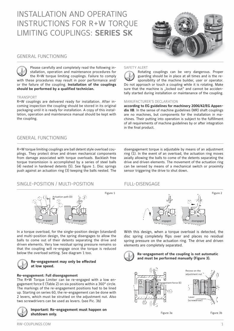
Mounting:Slide the coupling onto the shaft. lock it in position, with an end plate (8) for example. Figure 6.Dismounting: remove the end plate and slide the coupling off the shaft using an appropriate tool.
recommended to ease the mounting process and will not affect the clamping force of the hub.
CAUTION: Do not use sliding grease, or oils and grease with molybdenum disulfide or other high-pressure additives.
Mounting drive eleMentS to SK 1/SKp/SKn CouplingS + tigHtening torque SK CoMplete
SERIES 1,5 2 4,5 10 15 30 60 80/150 200 300 500 800 1500 2500Belt pre-tensioning force max. (n) a 25 50 100 300 700 900 1100 1500 1700 2200 2800 4000 5000 7000distance from - to (mm) B 3-6 5-8 6-11 6-14 7-17 10-24 10-24 10-24 12-26 12-28 16-38 16-42 20-50 28-60Fastening screws iSo 4762 Clamping hub
M2,5 M3 M4 M4 M5 M6 M8 M10 M12 M12 M16 2xM16 2xM20 x
tightening torque (nm) 1 2 4 4,5 8 15 40 70 120 130 200 250 470 xFastening screwsiSo 4762 Clamping hub SKn
x x x x M5 M6 M8 M10 M12 M12 M14 M16 M20 x
tightening torque Clamping hub SKn (nm)
x x x x 8 15 40 70 120 130 210 270 500 x
Fastening screwsiSo 4762 tapered bushing
x x x x M4 M5 M5 M6 M6 M8 M8 M10 M12 M16
tightening torque tapered bushing SKn (nm)
x x x x 4 6 8 12 14 18 25 40 70 120
Mounting of the drive element:Center the drive element (i.e. timing belt pulley or gear) onto the connecting flange of the coupling and fasten with screws. if the center of the radial load falls over the middle of the coupling an additional support bearing is not re-quired (figure 4). if the radial load is not centered over the coupling an additional support bearing is required (figure 5). please observe the maximum allowable radial load for each coupling size as indicated (table 1). excess radial load will affect the performance of the coupling.
table 1
Mounting: Slide the coupling onto the shaft to the proper axial position. using a torque wrench tighten the clamp screw (p) to the proper tightening torque as indicated in table 1.Dismounting: Simply loosen the clamp screw (p) and remove the coupling.
Mounting: Slide the coupling onto the shaft to the proper axial position. using a torque wrench, uniformly tighten the clamping screws (n) using a cross-wise tightening pattern until all the clamping screws are evenly tightened to the correct tighten-ing torque as given in table 1. While tightening the coupling may move slightly towards the tapered bushing.
CAUTION: Further tightening of the clamping screws may destroy the tapered bushing connection.
prior to reassembly make sure that the jack-screws are raised to their original position.
Dismounting: loosen the clamping screw (n). insert the three jack screws into the taped holes on the tapered segment apply even pressure to remove the ta-pered segment. remove the coupling.
SKP with key
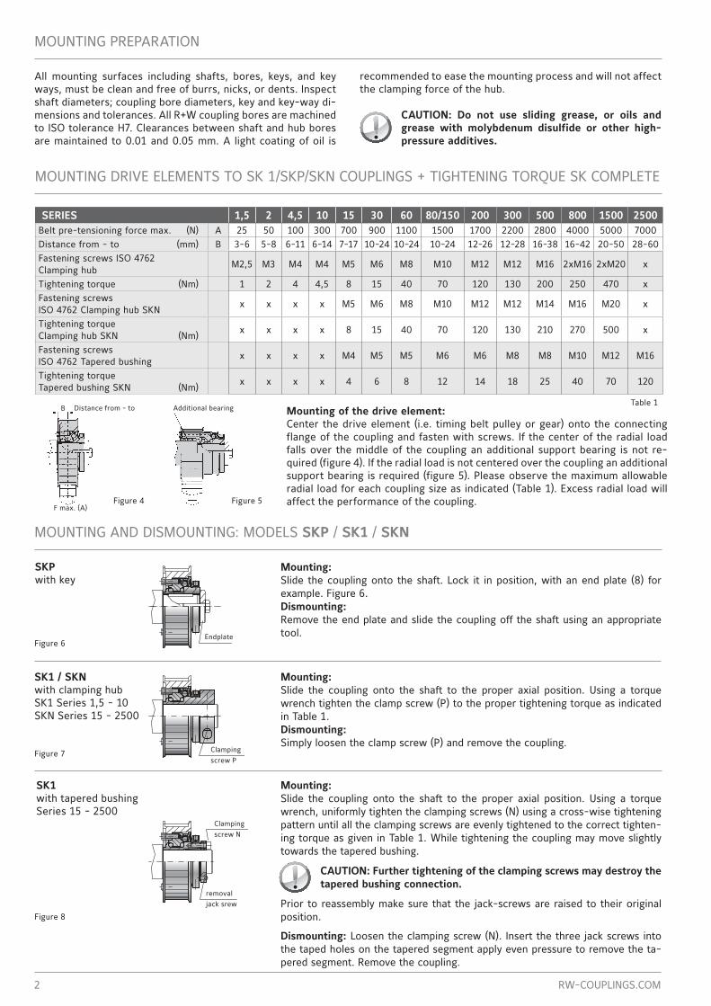
SK1 / SKN with clamping hub SK1 Series 1,5 - 10SKn Series 15 - 2500
SK1 with tapered bushingSeries 15 - 2500
Figure 7
Figure 8
Figure 5Figure 4
distance from - to additional bearingB
F max. (a)
Clamping screw n
removal jack srew
Clamping screw p
endplate
rW-CouplingS.CoM 3
Mounting and diSMounting SK2 / SK3 / SK5
Mounting:prior to mounting make sure that the shaft to be connected do not exceed the angular or lateral misalignment limits for the coupling size to be used. this data can be found in the catalog. Slide the coupling on the first shaft end to the proper axial position. using a torque wrench, tighten the clamp screw to the correct tightening torque as indicated in table 1. insert the second shaft into the other end of the coupling to the proper axial position. Make sure that the coupling is free of any axial forces before tightening. tighten the clamp screw as above using a torque wrench.Dismounting: Simply loosen the clamp screw and remove the coupling.
SK2 with clamping hub
Mounting:prior to mounting make sure that the shaft to be connected do not exceed the angular or lateral misalignment limits for the coupling size to be used. this data can be found in the catalog. Slide the coupling onto the first shaft to the proper axial position. using a torque wrench, uniformly tighten the clamping screws using a cross-wise tightening pattern until all the clamping screws are evenly tightened to the correct tightening torque as given in table 1.
CAUTION: Further tightening of the clamp screws may destroy the tapered bushing connection.
Dismounting: loosen the clamping screws. use the three jackscrews conveniently mounted in the taper segment to evenly back out the tapered segment. remove the coupling.
CAUTION: Prior to reassembly make sure that the jackscrews are raised to their original position.
SK3 with tapered bushing
Mounting:prior to mounting it is necessary to consider the overall length of the assembled coupling. the press-fit coupling requires a specific pre-tensioning (C) between the two coupling halves to ensure backlash free operation. Mount the „female” coupling half containing the bellow onto the first shaft end to the proper axial position. using a torque wrench tighten the clamp screw to the proper tighten-ing torque. Mount the „male” coupling segment onto the second shaft end. the proper axial position is when the two couplings come together and coupling is compressed by the proper pre-tension distance (C ). See table 2. When the coupling segment is properly positioned tighten the clamp screw to the proper torque.Dismounting: pull the coupling apart. Simply loosen the clamp screws and remove the coupling from the shaft.
SK5 with press-fit tapered bushings
aXial MiSalignMent
R+W bellows couplings compensate for lateral, axial and angular misalignment simultaneously.
Maximum shaft misalignment in addition to torque overload protection r+W torque limiters combined with a metal bellow compensate for lateral, axial and angular misalignment. table 2 contains the maximum allowable values for each axis of misalignment for the different size couplings. it is important to remain within these limits to ensure maximum life and proper operation of the coupling.
CAUTION: Exact alignment of the R+W metal bellow coupling consid-erably increases the service life of the coupling. Reducing or elimi-nating lateral misalignment eliminates the radial loading of the ad-
jacent bearings, increasing service life and reducing heat. For drives running at high speed it is recommended to align the coupling with a dial indicator.
SERIES 1,5 2 4,5 10 15 30 60 80/150 200 300 500 800 1500 2500lateral misalignment x/x (mm) ∆ Kr 0.15/0.20 0.15/0.20 0.20/0.25 0.20/0.30 0.15/0.20 0.20/0.25 0.20/0.25 0.20/0.25 0.25/0.30 0.25/0.30 0.30/0.35 0.35 0.35 0.4
axial misalignment x/x (mm) ∆ Ka 1/1.5 1/2 1/2 1/2 1/2 1/2 1.5/2 2/3 2/3 2.5/3.5 2.5/3.5 3.5 3.5 4
angular misalignment x/x (degree) ∆ Kw 1/1.5 1/1.5 1/1.5 1/1.5 1/1.5 1/1.5 1/1.5 1/1.5 1.5/2 1.5/2 2/2.5 2.5 2.5 2.5
pre-tensioning (mm) C 0.1-0.5 0.2-0.7 0.2-0.7 0.2-1.0 0.2-1.0 0.3-1.5 0.5-1.5 0.5-1.0 x 0.5-1.5 0.5-2.0 0.8-2.0 0.8-2.2 1-2.5
actuation path (mm) d 0.7 0.8 0.8 1.2 1.5 1.5 1.7 1.9 2.2 2.2 22 2.2 3 3
engagement force approx.(full disengage design) (n) e 5-10 8-15 10-20 15-30 20-40 25-50 40-80 50-100 80-150 100-220 250-700 800-1200
2000-3000
3000-4000
table 2 x/x First values are for bellows with 4-5 currigations. Second values are for bellows with 6-8 currigations.
lateral misalignment ∆ Kr
axial misalignment ∆ Ka
angular misalignment ∆ Kw
Figure 9
Figure 10
Figure 11
Figure 12
pre-tensioningC
rW-CouplingS.CoM4
eMergenCY SWitCH FunCtion
11/2
014/
2500 R+W Antriebselemente GmbH
alexander-Wiegand-Str. 8 · 63911 Klingenbergphone +49 9372 9864-0 · Fax +49 9372 [email protected] · www.rw-couplings.com
the above-mentioned information is based on our present knowledge and experiences and does not free the user of his own regular checks. a legally binding guarantee is not given even in regard to protection rights of third parties.
MaintenanCe
r+W torque limiters are maintenance free as long as they are properly mounted and the maximum misalignment and radial load values are not exceeded. the internal components are per-manently greased for lifetime lubrication.
CAUTION:Disassembly of the coupling will void the warranty.
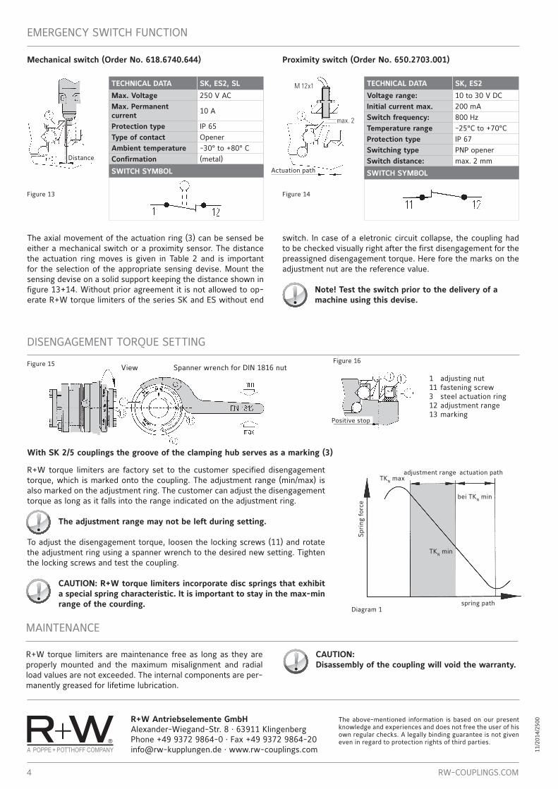
Mechanical switch (Order No. 618.6740.644) Proximity switch (Order No. 650.2703.001)
M 12x1
max. 2
TECHNICAL DATA SK, ES2, SL
Max. Voltage 250 v aCMax. Permanent current 10 a
Protection type ip 65Type of contact openerAmbient temperature -30° to +80° CConfirmation (metal)
SWITCH SYMBOL
the axial movement of the actuation ring (3) can be sensed be either a mechanical switch or a proximity sensor. the distance the actuation ring moves is given in table 2 and is important for the selection of the appropriate sensing devise. Mount the sensing devise on a solid support keeping the distance shown in figure 13+14. Without prior agreement it is not allowed to op-erate r+W torque limiters of the series SK and eS without end
TECHNICAL DATA SK, ES2
Voltage range: 10 to 30 v dCInitial current max. 200 maSwitch frequency: 800 HzTemperature range -25°C to +70°CProtection type ip 67Switching type pnp openerSwitch distance: max. 2 mm
SWITCH SYMBOL
switch. in case of a eletronic circuit collapse, the coupling had to be checked visually right after the first disengagement for the preassigned disengagement torque. Here fore the marks on the adjustment nut are the reference value.
Note! Test the switch prior to the delivery of a machine using this devise.
Figure 13 Figure 14
diSengageMent torque Setting
view Spanner wrench for din 1816 nut1 adjusting nut 11 fastening screw 3 steel actuation ring12 adjustment range13 marking
r+W torque limiters are factory set to the customer specified disengagement torque, which is marked onto the coupling. the adjustment range (min/max) is also marked on the adjustment ring. the customer can adjust the disengagement torque as long as it falls into the range indicated on the adjustment ring.
The adjustment range may not be left during setting.
to adjust the disengagement torque, loosen the locking screws (11) and rotate the adjustment ring using a spanner wrench to the desired new setting. tighten the locking screws and test the coupling.
CAUTION: R+W torque limiters incorporate disc springs that exhibit a special spring characteristic. It is important to stay in the max-min range of the courding.
diagram 1
adjustment range actuation path
tKn min
spring path
Spri
ng f
orce
tKn max
bei tKn min
With SK 2/5 couplings the groove of the clamping hub serves as a marking (3)
distance
actuation path
positive stop
Figure 15 Figure 16