Embed Size (px)
Citation preview
Revenge® Riflescope Owner’s ManualComplete Installation & Operating Instructions

2
The Redfield ® Story
Born in 1859 on a farm near Glendale, Oregon, John Hill Redfield was one of eight children of John and Adelia Redfield.
As a boy, John loved to hunt and explore the regions around the homestead. Eventually, John’s mechanical aptitudes and inventiveness led him into the firearms industry, and in 1909, John started the Redfield Gun Sight Co.
A small building behind his home served as his first factory. From this humble beginning, the company expanded its offerings to include scope mounts and eventually a premier line of riflescopes for which it was widely known.
In 1997, Redfield closed its manufacturing facility in the United States and spent most of the next decade languishing as a name used by various companies.
In 2008, Leupold & Stevens, an Oregon company with a long tradition of manufacturing optical instruments, purchased the Redfield optics brand and committed to bringing hunters a new generation of Redfield riflescopes. These new products embody the values that Leupold and Redfield shared: ruggedness, performance, durability, and value. We hope your new Redfield riflescope brings you years of success and enjoyment in the field.
3
Before You Start
PLEASE READ THIS ENTIRE HANDBOOK BEFORE MOUNTING YOUR SCOPE.
CAUTION: Always check and be certain that the firearm is unloaded before undertaking any work upon it.
4
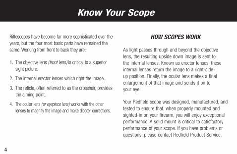
Riflescopes have become far more sophisticated over the years, but the four most basic parts have remained the same. Working from front to back they are:
1. The objective lens (front lens) is critical to a superior sight picture.
2. The internal erector lenses which right the image.
3. The reticle, often referred to as the crosshair, provides the aiming point.
4. The ocular lens (or eyepiece lens) works with the other lenses to magnify the image and make diopter corrections.
HOW SCOPES WORK
As light passes through and beyond the objective lens, the resulting upside down image is sent to the internal lenses. Known as erector lenses, these internal lenses return the image to a right-side-up position. Finally, the ocular lens makes a final enlargement of that image and sends it on to your eye.
Your Redfield scope was designed, manufactured, and tested to ensure that, when properly mounted and sighted-in on your firearm, you will enjoy exceptional performance. A solid mount is critical to satisfactory performance of your scope. If you have problems or questions, please contact Redfield Product Service.
Know Your Scope
5
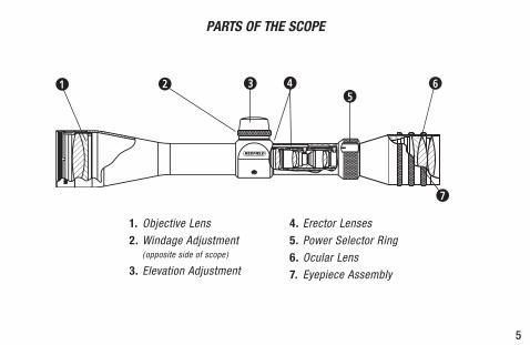
1. Objective Lens2. Windage Adjustment
(opposite side of scope)
3. Elevation Adjustment
4. Erector Lenses5. Power Selector Ring 6. Ocular Lens7. Eyepiece Assembly
PARTS OF THE SCOPE
35
6
7
421
6
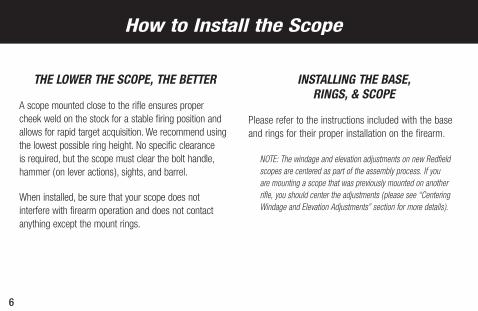
THE LOWER THE SCOPE, THE BETTER
A scope mounted close to the rifle ensures proper cheek weld on the stock for a stable firing position and allows for rapid target acquisition. We recommend using the lowest possible ring height. No specific clearance is required, but the scope must clear the bolt handle, hammer (on lever actions), sights, and barrel.
When installed, be sure that your scope does not interfere with firearm operation and does not contact anything except the mount rings.
INSTALLING THE BASE, RINGS, & SCOPE
Please refer to the instructions included with the base and rings for their proper installation on the firearm.
NOTE: The windage and elevation adjustments on new Redfield scopes are centered as part of the assembly process. If you are mounting a scope that was previously mounted on another rifle, you should center the adjustments (please see “Centering Windage and Elevation Adjustments” section for more details).
How to Install the Scope
7
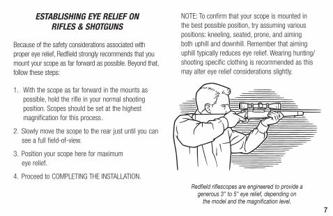
ESTABLISHING EYE RELIEF ON RIFLES & SHOTGUNS
Because of the safety considerations associated with proper eye relief, Redfield strongly recommends that you mount your scope as far forward as possible. Beyond that, follow these steps:
1. With the scope as far forward in the mounts as possible, hold the rifle in your normal shooting position. Scopes should be set at the highest magnification for this process.
2. Slowly move the scope to the rear just until you can see a full field-of-view.
3. Position your scope here for maximum eye relief.
4. Proceed to COMPLETING THE INSTALLATION.
NOTE: To confirm that your scope is mounted in the best possible position, try assuming various positions: kneeling, seated, prone, and aiming both uphill and downhill. Remember that aiming uphill typically reduces eye relief. Wearing hunting/shooting specific clothing is recommended as this may alter eye relief considerations slightly.
Redfield riflescopes are engineered to provide a generous 3" to 5" eye relief, depending on
the model and the magnification level.
8
COMPLETING THE INSTALLATION
Without disturbing the optimal eye relief position, rotate the scope until the elevation adjustment dial is at the top of the scope.
From a firing position, check to be sure that the vertical line of the reticle aligns with the vertical axis of the firearm. Misalignment will not affect accuracy at moderate distances but it can diminish long range accuracy.
When you are satisfied, tighten the ring screws evenly and securely following the instructions included with the rings.
FOCUSING THE RETICLE
Secure the scope and firearm in a firm rest. Safely point the scope at a light colored background object. With the scope approximately four inches from your eye the reticle should appear sharp and crisp; if it does not, it is necessary to adjust the focus by means of the rubber ring on the eyepiece following these steps:
1. If you tend to hold things away from yourself to see them clearly (you are farsighted) turn the rubber ring counter-clockwise. If you hold things close to yourself to see them clearly (you are nearsighted) turn the ring clockwise.
WARNING: If a scope is mounted too far to the rear, the eyepiece
can injure the shooter’s brow. Shooting at an uphill angle also increases this hazard because it shortens the distance between the brow and the rear of the scope. For this reason, Redfield scopes are engineered to provide generous eye relief. Therefore, when mounting your scope, we recommend positioning it as far forward in the mounts as possible to take full advantage of this generous eye relief.
9
2. Looking through the scope when pointed at a light colored background object, take a few quick glances at the reticle. The focus of the reticle should be noticeably different from when you started. Continue this process until the reticle appears clear and sharp.
3. If your eyesight changes, readjust the eyepiece. As we age, eyesight normally changes. You may want to check the sharpness of the reticle on your scope every few years to ensure it is still adjusted correctly for your eye. NOTE: To protect the integrity of the waterproof seal of every Redfield scope, an internal mechanism prevents the eyepiece from being removed.
The primary function of a scope is to aim the firearm. Never use the scope as a substitute for binoculars. Never watch another person through the scope. As always, safety first.
WHAT YOU SHOULD KNOW ABOUT VARIABLE POWER SCOPES
Redfield variable power scopes allow you to select from a range of magnifications to suit your particular rifle, cartridge, and shooting needs.
WARNING: Do not loosen the screw in the power selector ring. Doing so will release the internal gas that keeps the scope fog free. Loosening the screw will also disconnect a pin that controls the internal operations, causing other problems that will require factory repairs. Do not lubricate the power selector ring; doing so is unnecessary.
All variable power scopes have a power selector ring in front of the eyepiece assembly. Turn the ring to align the indicator marked on the ring with the desired magnification marked on the body of the scope.
10
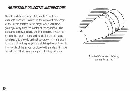
ADJUSTABLE OBJECTIVE INSTRUCTIONS
Select models feature an Adjustable Objective to eliminate parallax. Parallax is the apparent movement of the reticle relative to the target when you move your eye away from the center of the eyepiece. The adjustment moves a lens within the optical system to ensure the target image and reticle fall on the same focal plane to provide optimal accuracy. It is important to note that as long as you are sighting directly through the middle of the scope, or close to it, parallax will have virtually no effect on accuracy in a hunting situation.
To adjust the parallax distance, turn the focus ring.
11
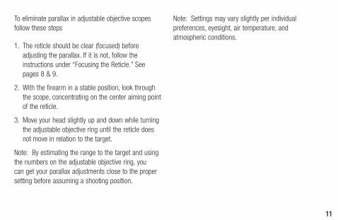
To eliminate parallax in adjustable objective scopes follow these steps
1. The reticle should be clear (focused) before adjusting the parallax. If it is not, follow the instructions under “Focusing the Reticle.” See pages 8 & 9.
2. With the firearm in a stable position, look through the scope, concentrating on the center aiming point of the reticle.
3. Move your head slightly up and down while turning the adjustable objective ring until the reticle does not move in relation to the target.
Note: By estimating the range to the target and using the numbers on the adjustable objective ring, you can get your parallax adjustments close to the proper setting before assuming a shooting position.
Note: Settings may vary slightly per individual preferences, eyesight, air temperature, and atmospheric conditions.
12
USING A BORE-SIGHTING COLLIMATOR
To save time and ammunition, start out in your shop or gun room with a bore-sighting collimator. Follow the directions included with the collimator for specific instructions on its proper use. Remember, when possible, it is better to make the initial windage adjustments to the mount base before using the scope’s windage adjustment. Leupold STD mounts provide the maximum adjustment travel by providing windage adjustment in the mount system. When using STD mounts, always make the windage adjustment in the mount first, then refine this setting using the riflescope windage adjustment.
NOTE: Bore-sighting alone is not sufficient to sight-in a scope. You must make final adjustments by shooting the firearm using the same ammunition you use in the field.
USING THE LEUPOLD® ZERO POINT® ILLUMINATED MAGNETIC BORESIGHTER
This tool fits any rifle, shotgun, or pistol, and helps you get “on the paper” fast, without barrel spuds. It works with any optical sight, and can even be used to recheck your zero, without firing a shot. See your Leupold Dealer or visit www.leupold.com for more information.
How to Sight-In
13
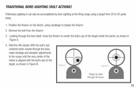
TRADITIONAL BORE-SIGHTING (BOLT ACTIONS)
Preliminary sighting-in can also be accomplished by bore-sighting at the firing range using a target from 20 to 50 yards away.
1. Position the firearm on the bench, using sandbags to steady the firearm.
2. Remove the bolt from the firearm.
3. Looking through the bore itself, move the firearm to center the bull’s-eye of the target inside the barrel, as shown in Figure A.
4. Hold the rifle steady. With the bull’s-eye centered when viewed through the bore, make windage and elevation adjustments to the scope until the very center of the reticle is aligned with the bull’s-eye of the target, as shown in Figure B.
Target as seen through the bore.
Figure A Figure B
14
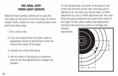
THE FINAL STEP: THREE-SHOT GROUPS
Whichever bore-sighting method you’ve used, the next steps are the same on the firing range. To ensure reliable results, always fire from a rested position when performing these steps.
1. Fire a shot or two.
2. If you are several inches off center, make an appropriate amount of adjustment to move the reticle to the center of the target.
3. Carefully fire a three-shot group.
4. Use the center of that group as a reference point for the final adjustments to windage and elevation.
On the sample target, the center of the group is two inches low and three inches right. Assuming you’re sighting-in at 100 yards, you should make a 2-MOA adjustment up, and a 3-MOA adjustment left. Your next three-shot group should be very close to the center of the target. To learn about making final adjustments, proceed to the upcoming section on windage and elevation adjustments.
15
All Revenge scopes feature 1/4 MOA precision finger-click / resettable adjustments (except 1/8 MOA 6-18x scopes), and the letters found on the elevation and windage dials refer to the direction that the point-of-impact of the bullet is moved when an adjustment is made. To make an elevation correction, simply remove the elevation adjustment cover located on the top of the scope, and rotate the dial the necessary amount. The adjustment will move the bullet impact in the direction indicated on the dial. For example, if you would like the bullet to impact 2 inches higher at 100 yards, you would rotate the elevation dial 8 clicks (2 MOA) in the “up” (counter-clockwise) direction.
The same is true for windage adjustments. To make a windage correction simply remove the adjustment
cover on the side of the scope and rotate the dial in the left or right direction the appropriate number of clicks.
ZEROING THE WINDAGE & ELEVATION DIALS AFTER SIGHTING IN
Redfield scopes feature adjustment dials that can be repositioned to align with the marked zero indicator of the adjustment without changing the adjustment setting of the scope. This allows the shooter to know the original zero of the rifle in the event that further adjustments are made in the field.
To reset the zero simply lift the dial and rotate it until the "0" on the dial is aligned with the zero indicator of the adjustment (excludes DNS elevation).
Making Precise Windage & Elevation Adjustments
16
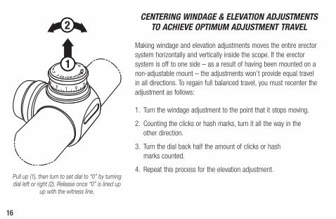
Pull up (1), then turn to set dial to “0” by turning dial left or right (2). Release once “0” is lined up
up with the witness line.
CENTERING WINDAGE & ELEVATION ADJUSTMENTS TO ACHIEVE OPTIMUM ADJUSTMENT TRAVEL
Making windage and elevation adjustments moves the entire erector system horizontally and vertically inside the scope. If the erector system is off to one side – as a result of having been mounted on a non-adjustable mount – the adjustments won’t provide equal travel in all directions. To regain full balanced travel, you must recenter the adjustment as follows:
1. Turn the windage adjustment to the point that it stops moving.
2. Counting the clicks or hash marks, turn it all the way in the other direction.
3. Turn the dial back half the amount of clicks or hash marks counted.
4. Repeat this process for the elevation adjustment.
1
2
17
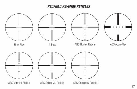
REDFIELD REVENGE RETICLES
ABS Hunter Reticle
ABS Varmint Reticle ABS Sabot ML Reticle
Fine-Plex 4-Plex
ABS Crossbow Reticle
ABS Accu-Plex
18
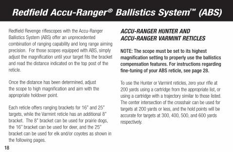
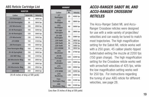
Redfield Revenge riflescopes with the Accu-Ranger Ballistics System (ABS) offer an unprecedented combination of ranging capability and long range aiming precision. For those scopes equipped with ABS, simply adjust the magnification until your target fits the bracket and read the distance indicated on the top post of the reticle.
Once the distance has been determined, adjust the scope to high magnification and aim with the appropriate holdover point.
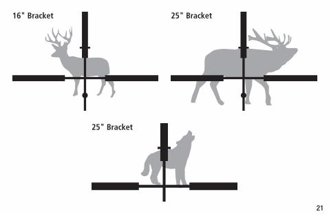
Each reticle offers ranging brackets for 16” and 25” targets, while the Varmint reticle has an additional 8” bracket. The 8” bracket can be used for prairie dogs, the 16” bracket can be used for deer, and the 25” bracket can be used for elk and/or coyotes as shown in the following pages.
ACCU-RANGER HUNTER AND ACCU-RANGER VARMINT RETICLES
NOTE: The scope must be set to its highest magnification setting to properly use the ballistics compensation features. For instructions regarding fine-tuning of your ABS reticle, see page 28.
To use the Hunter or Varmint reticles, zero your rifle at 200 yards using a cartridge from the appropriate list, or using a cartridge with a trajectory similar to those listed. The center intersection of the crosshair can be used for targets at 200 yards or less, and the hold points will be accurate for targets at 300, 400, 500, and 600 yards respectively.
Redfield Accu-Ranger® Ballistics System™ (ABS)
19
(35-45 inches of drop at 500 yards)
HUNTER
Caliber Bullet Wt. Velocity
.223 Remington 40 3800 fps
.22-250 Remington 55 3650 fps
.243 Winchester 100 2900 fps
.25-06 Remington 100 3200 fps
.25-06 Remington 120 3000 fps
.270 Winchester 130 3050 fps
.270 WSM 150 3120 fps
.280 Remington 140 3000 fps
7mm Remington Mag 150 3050 fps
.30-06 Springfield 150 3000 fps
.300 WBY Mag 180 3100 fps
.300 Winchester Mag 180 2950 fps
.300 WSM 180 2950 fps
.338 Winchester Mag 200 2950 fps
.338 RUM 250 2900 fps
(Less than 35 inches of drop at 500 yards)
ABS Reticle Cartridge List ACCU-RANGER SABOT ML AND ACCU-RANGER CROSSBOW RETICLES
The Accu-Ranger Sabot ML and Accu-Ranger Crossbow reticles were designed for use with a wide variety of projectiles/velocities and can easily be tuned to match most trajectories. The high magnification setting for the Sabot ML reticle works well with a 250 grain, 45 caliber plastic-tipped bullet/sabot exiting the muzzle at 2200 fps (150 grain charge). The high magnification setting for the Crossbow reticle works well with arrow/bolt velocities of 425 fps, while the low magnification setting works well for 250 fps. For instructions regarding the tuning of your ABS reticle for different velocities, see page 28.
VARMINT
20
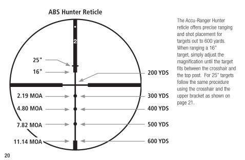
ABS Hunter ReticleThe Accu-Ranger Hunter reticle offers precise ranging and shot placement for targets out to 600 yards. When ranging a 16” target, simply adjust the magnification until the target fits between the crosshair and the top post. For 25” targets follow the same procedure using the crosshair and the upper bracket as shown on page 21.
200 YDS
300 YDS2.19 MOA
400 YDS4.80 MOA
500 YDS
600 YDS11.14 MOA
7.82 MOA
25"
16"
21
25" Bracket16" Bracket
25" Bracket
22
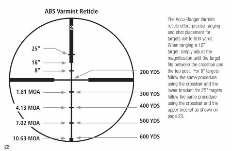
The Accu-Ranger Varmint reticle offers precise ranging and shot placement for targets out to 600 yards. When ranging a 16” target, simply adjust the magnification until the target fits between the crosshair and the top post. For 8” targets follow the same procedure using the crosshair and the lower bracket; for 25” targets follow the same procedure using the crosshair and the upper bracket as shown on page 23.
ABS Varmint Reticle
200 YDS
300 YDS
400 YDS
500 YDS
600 YDS
1.81 MOA
10.63 MOA
7.02 MOA
4.13 MOA
25"
16"8"
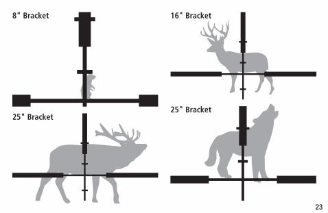
23
25" Bracket
16" Bracket
25" Bracket
8" Bracket
24
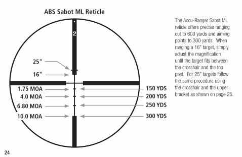
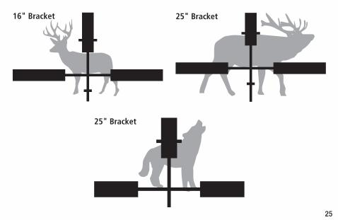
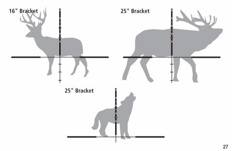
The Accu-Ranger Sabot ML reticle offers precise ranging out to 600 yards and aiming points to 300 yards. When ranging a 16” target, simply adjust the magnification until the target fits between the crosshair and the top post. For 25” targets follow the same procedure using the crosshair and the upper bracket as shown on page 25.
ABS Sabot ML Reticle
25"
16"
150 YDS200 YDS250 YDS
300 YDS
1.75 MOA
10.0 MOA
6.80 MOA
4.0 MOA
25
25" Bracket16" Bracket
25" Bracket
26
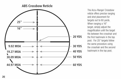
The Accu-Ranger Crossbow reticle offers precise ranging and shot placement for targets out to 60 yards. When ranging a 16” target, simply adjust the magnification until the target fits between the crosshair and the first hashmark in the top post. For 25” targets follow the same procedure using the crosshair and the second hashmark in the top post.
ABS Crossbow Reticle
20 YDS
30 YDS
40 YDS
50 YDS
60 YDS
9.02 MOA
44.97 MOA
30.09 MOA
19.27 MOA
25"
16"
27
25" Bracket16" Bracket
25" Bracket
28
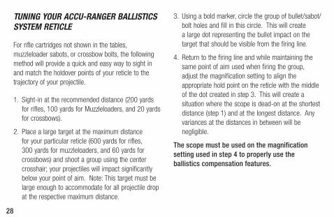
TUNING YOUR ACCU-RANGER BALLISTICS SYSTEM RETICLE
For rifle cartridges not shown in the tables, muzzleloader sabots, or crossbow bolts, the following method will provide a quick and easy way to sight in and match the holdover points of your reticle to the trajectory of your projectile.
1. Sight-in at the recommended distance (200 yards for rifles, 100 yards for Muzzleloaders, and 20 yards for crossbows).
2. Place a large target at the maximum distance for your particular reticle (600 yards for rifles, 300 yards for muzzleloaders, and 60 yards for crossbows) and shoot a group using the center crosshair; your projectiles will impact significantly below your point of aim. Note: This target must be large enough to accommodate for all projectile drop at the respective maximum distance.
3. Using a bold marker, circle the group of bullet/sabot/bolt holes and fill in this circle. This will create a large dot representing the bullet impact on the target that should be visible from the firing line.
4. Return to the firing line and while maintaining the same point of aim used when firing the group, adjust the magnification setting to align the appropriate hold point on the reticle with the middle of the dot created in step 3. This will create a situation where the scope is dead-on at the shortest distance (step 1) and at the longest distance. Any variances at the distances in between will be negligible.
The scope must be used on the magnification setting used in step 4 to properly use the ballistics compensation features.
29
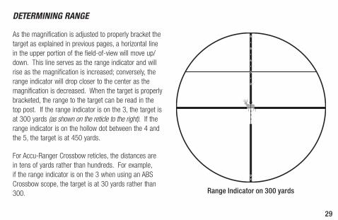
DETERMINING RANGE
As the magnification is adjusted to properly bracket the target as explained in previous pages, a horizontal line in the upper portion of the field-of-view will move up/down. This line serves as the range indicator and will rise as the magnification is increased; conversely, the range indicator will drop closer to the center as the magnification is decreased. When the target is properly bracketed, the range to the target can be read in the top post. If the range indicator is on the 3, the target is at 300 yards (as shown on the reticle to the right). If the range indicator is on the hollow dot between the 4 and the 5, the target is at 450 yards.
For Accu-Ranger Crossbow reticles, the distances are in tens of yards rather than hundreds. For example, if the range indicator is on the 3 when using an ABS Crossbow scope, the target is at 30 yards rather than 300. Range Indicator on 300 yards
30
NOTE: Once the range has been determined, the scope must be turned to high magnification prior to using any long range hold points while shooting.
As a reminder that the scope must be used on high magnification, the maximum power setting (i.e.: 9x) has been written in the lower portion of the bottom post. For Sabot ML and Crossbow reticles, the scope will need to be set to the predetermined magnification setting for your particular trajectory (see page 28) prior to shooting.
Be sure to verify the aiming points by practicing at the actual distances at which the points are intended to work. Ballistics performance of your rifle and cartridge can vary somewhat from ammunition manufacturer data due to rifle barrel length, actual ammunition performance, and various atmospheric conditions.
If the bullet/arrow is hitting slightly above the intended hold point when shooting, increase the magnification slightly. If the projectile is hitting below the intended hold point, decrease the magnification slightly.
31
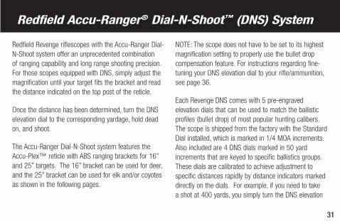
Redfield Accu-Ranger® Dial-N-Shoot™ (DNS) System
Redfield Revenge riflescopes with the Accu-Ranger Dial-N-Shoot system offer an unprecedented combination of ranging capability and long range shooting precision. For those scopes equipped with DNS, simply adjust the magnification until your target fits the bracket and read the distance indicated on the top post of the reticle.
Once the distance has been determined, turn the DNS elevation dial to the corresponding yardage, hold dead on, and shoot.
The Accu-Ranger Dial-N-Shoot system features the Accu-Plex™ reticle with ABS ranging brackets for 16” and 25” targets. The 16” bracket can be used for deer, and the 25” bracket can be used for elk and/or coyotes as shown in the following pages.
NOTE: The scope does not have to be set to its highest magnification setting to properly use the bullet drop compensation feature. For instructions regarding fine-tuning your DNS elevation dial to your rifle/ammunition, see page 36.
Each Revenge DNS comes with 5 pre-engraved elevation dials that can be used to match the ballistic profiles (bullet drop) of most popular hunting calibers. The scope is shipped from the factory with the Standard Dial installed, which is marked in 1/4 MOA increments. Also included are 4 DNS dials marked in 50 yard increments that are keyed to specific ballistics groups. These dials are calibrated to achieve adjustment to specific distances rapidly by distance indicators marked directly on the dials. For example, if you need to take a shot at 400 yards, you simply turn the DNS elevation
32
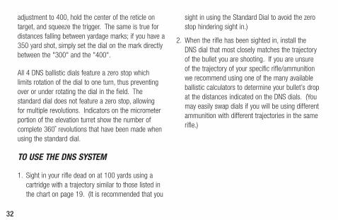
adjustment to 400, hold the center of the reticle on target, and squeeze the trigger. The same is true for distances falling between yardage marks; if you have a 350 yard shot, simply set the dial on the mark directly between the "300" and the "400".
All 4 DNS ballistic dials feature a zero stop which limits rotation of the dial to one turn, thus preventing over or under rotating the dial in the field. The standard dial does not feature a zero stop, allowing for multiple revolutions. Indicators on the micrometer portion of the elevation turret show the number of complete 360˚ revolutions that have been made when using the standard dial.
TO USE THE DNS SYSTEM
1. Sight in your rifle dead on at 100 yards using a cartridge with a trajectory similar to those listed in the chart on page 19. (It is recommended that you
sight in using the Standard Dial to avoid the zero stop hindering sight in.)
2. When the rifle has been sighted in, install the DNS dial that most closely matches the trajectory of the bullet you are shooting. If you are unsure of the trajectory of your specific rifle/ammunition we recommend using one of the many available ballistic calculators to determine your bullet’s drop at the distances indicated on the DNS dials. (You may easily swap dials if you will be using different ammunition with different trajectories in the same rifle.)
33
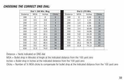
CHOOSING THE CORRECT DNS DIAL:
Distance MOA Inches Clicks Distance MOA Inches Clicks100 0 0 0 100 0 0.00 0150 0.5 0.8 2 150 0.7 1.10 3200 1.0 2.1 4 200 1.4 2.93 6250 1.9 5.0 8 250 2.4 6.28 10300 2.8 8.8 11 300 3.4 10.68 14350 3.8 13.9 15 350 4.6 16.86 18400 4.8 20.1 19 400 5.8 24.29 23450 5.9 27.8 24 450 7.2 33.92 29500 7.0 36.6 28 500 8.6 45.02 34550 8.4 48.4 34 550 10.2 58.74 41600 9.6 60.3 38 600 11.8 74.13 47650 11.0 74.9 44
Dial 1-.300 Win. Mag. Dial 2-.270 Win.
Distance = Yards indicated on DNS dial MOA = Bullet drop in Minutes of Angle at the indicated distance from the 100 yard zero Inches = Bullet drop in inches at the indicated distance from the 100 yard zero Clicks = Number of ¼ MOA clicks to compensate for bullet drop at the indicated distance from the 100 yard zero
34
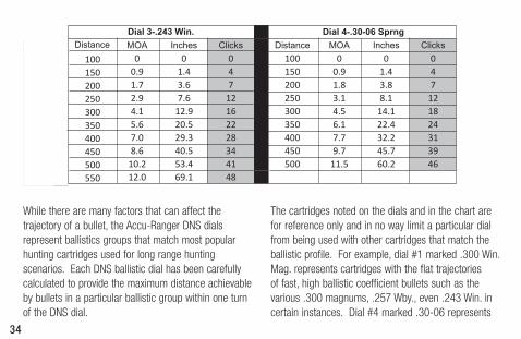
While there are many factors that can affect the trajectory of a bullet, the Accu-Ranger DNS dials represent ballistics groups that match most popular hunting cartridges used for long range hunting scenarios. Each DNS ballistic dial has been carefully calculated to provide the maximum distance achievable by bullets in a particular ballistic group within one turn of the DNS dial.
The cartridges noted on the dials and in the chart are for reference only and in no way limit a particular dial from being used with other cartridges that match the ballistic profile. For example, dial #1 marked .300 Win. Mag. represents cartridges with the flat trajectories of fast, high ballistic coefficient bullets such as the various .300 magnums, .257 Wby., even .243 Win. in certain instances. Dial #4 marked .30-06 represents
MOA Inches Clicks Distance MOA Inches Clicks0 0 0 100 0 0 0
0.9 1.4 4 150 0.9 1.4 41.7 3.6 7 200 1.8 3.8 72.9 7.6 12 250 3.1 8.1 124.1 12.9 16 300 4.5 14.1 185.6 20.5 22 350 6.1 22.4 247.0 29.3 28 400 7.7 32.2 318.6 40.5 34 450 9.7 45.7 39
10.2 53.4 41 500 11.5 60.2 4612.0 69.1 48
Dial 3-.243 Win. Dial 4-.30-06 SprngClicks Distance
0 1003 1506 200
10 25014 30018 35023 40029 45034 50041 55047
35
slower speeds and/or lower ballistic coefficients, such as .308 Win. and .223 Rem. The key is matching the trajectory of the bullet you will be shooting, in the conditions you will be shooting it, as closely as possible to the drops calculated for one of the DNS dials. If you are unsure of the trajectory of your chosen ammunition, from your rifle, we recommend using one of the many ballistic calculators available to determine your bullet’s drop at varying distances. Once you have selected a dial be sure to verify the bullet drop compensation by practicing at the actual distances at which the dials are calculated to work. Ballistics performance of your rifle and cartridge can vary somewhat from ammunition manufacturer data due to rifle barrel length, actual ammunition performance, and various atmospheric conditions.
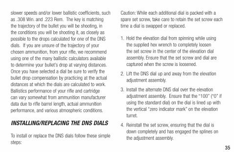
INSTALLING/REPLACING THE DNS DIALS
To install or replace the DNS dials follow these simple steps:
Caution: While each additional dial is packed with a spare set screw, take care to retain the set screw each time a dial is swapped or replaced.
1. Hold the elevation dial from spinning while using the supplied hex wrench to completely loosen the set screw in the center of the elevation dial assembly. Ensure that the set screw and dial are captured when the screw is loosened.
2. Lift the DNS dial up and away from the elevation adjustment assembly.
3. Install the alternate DNS dial over the elevation adjustment assembly. Ensure that the “100” (“0” if using the standard dial) on the dial is lined up with the vertical “zero indicator mark” on the elevation turret.
4. Reinstall the set screw, ensuring that the dial is down completely and has engaged the splines on the adjustment assembly.
36
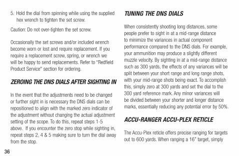
5. Hold the dial from spinning while using the supplied hex wrench to tighten the set screw.
Caution: Do not over-tighten the set screw.
Occasionally the set screws and/or included wrench become worn or lost and require replacement. If you require a replacement screw, spring, or wrench we will be happy to send replacements. Refer to “Redfield Product Service" section for ordering.
ZEROING THE DNS DIALS AFTER SIGHTING IN
In the event that the adjustments need to be changed or further sight in is necessary the DNS dials can be repositioned to align with the marked zero indicator of the adjustment without changing the actual adjustment setting of the scope. To do this, repeat steps 1-5 above. If you encounter the zero stop while sighting in, repeat steps 2, 4 & 5 making sure to turn the dial away from the stop.
TUNING THE DNS DIALS
When consistently shooting long distances, some people prefer to sight in at a mid-range distance to minimize the variances in actual component performance compared to the DNS dials. For example, your ammunition may produce a slightly different muzzle velocity. By sighting in at a mid-range distance such as 300 yards, the effects of any variances will be split between your short range and long range shots, with your mid-range shots being exact. To accomplish this, simply zero at 300 yards and set the dial to the 300 yard reference mark. Any minor variances will be divided between your shorter and longer distance marks, essentially reducing any potential error by 50%.
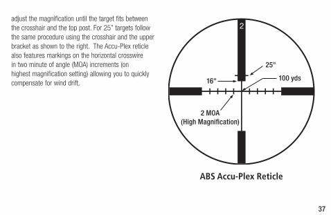
ACCU-RANGER ACCU-PLEX RETICLE
The Accu-Plex reticle offers precise ranging for targets out to 600 yards. When ranging a 16” target, simply
37
ABS Accu-Plex Reticle
25"
16" 100 yds
2 MOA(High Magnification)
adjust the magnification until the target fits between the crosshair and the top post. For 25” targets follow the same procedure using the crosshair and the upper bracket as shown to the right. The Accu-Plex reticle also features markings on the horizontal crosswire in two minute of angle (MOA) increments (on highest magnification setting) allowing you to quickly compensate for wind drift.
38
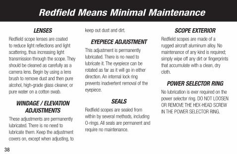
LENSESRedfield scope lenses are coated to reduce light reflections and light scattering, thus increasing light transmission through the scope. They should be cleaned as carefully as a camera lens. Begin by using a lens brush to remove dust and then pure alcohol, high-grade glass cleaner, or pure water on a cotton swab.
WINDAGE / ELEVATION ADJUSTMENTS
These adjustments are permanently lubricated. There is no need to lubricate them. Keep the adjustment covers on, except when adjusting, to
keep out dust and dirt.
EYEPIECE ADJUSTMENTThis adjustment is permanently lubricated. There is no need to lubricate it. The eyepiece can be rotated as far as it will go in either direction. An internal lock ring prevents inadvertent removal of the eyepiece.
SEALSRedfield scopes are sealed from within by several methods, including O-rings. All seals are permanent and require no maintenance.
SCOPE EXTERIORRedfield scopes are made of a rugged aircraft aluminum alloy. No maintenance of any kind is required; simply wipe off any dirt or fingerprints that accumulate with a clean, dry cloth.
POWER SELECTOR RINGNo lubrication is ever required on the power selector ring. DO NOT LOOSEN OR REMOVE THE HEX-HEAD SCREW IN THE POWER SELECTOR RING.
Redfield Means Minimal Maintenance
39
TROUBLE SHOOTING TIPS
Before you ship a scope back to the factory for service or repair, please check the following items.
1. Check the mount. Make sure the scope is mounted securely to the rifle. Try, with bare hands only, to gently twist the scope in the rings or see if anything moves when you jiggle it. If there is any movement, retighten the mounting system according to mounting instructions.
2. Make sure the action of your rifle is properly bedded in the stock, and that all receiver screws are tight and have been tightened in the sequence recommended by the manufacturer. A loosely fitted stock can cause changes to the point-of-impact.
3. When test firing a rifle to check the point-of-impact relative to windage and elevation adjustments, be sure to fire from a solid bench with sandbags supporting the forearm and buttstock.
4. Be sure to use factory-loaded ammunition of the same bullet type, weight, and preferably, lot number. If one type of ammunition does not shoot well, try another brand or bullet weight.
5. Be certain that both the barrel and chamber are clean. Heavy factory grease or copper fouling can diminish the accuracy of the firearm.
40
If your Redfield scope fails to perform in any way, you may return it directly to the factory (or one of our international service centers) for service. It is not necessary for your dealer to ship the scope to Redfield; however, they can be very helpful in determining if factory service is necessary. Please follow these shipping instructions:
1. Remove the rings and any other accessories from the scope.
2. Record the serial number of the scope and keep it for your records.
3. Include a note with your name, address, telephone number, E-mail, and a description of the problem.
4. Pack the scope in its original box if possible, as this is the safest shipping container. Wrap the package
securely using filament strapping tape on the outside.
5. Ship the scope by parcel or mail service ( insured, if possible) to one of the following addresses:
In the United States:
Parcel Service: Redfield Product Service 14400 NW Greenbrier Parkway Beaverton, OR 97006-5790 USA
By Mail: Redfield Product Service P.O. Box 688 Beaverton, OR 97075-0688 USA
Redfield Product Service
41
Outside the United States:
Canada: Korth Group Ltd., 103 Stockton Point, Box 490 Okotoks, AB T0L 1T0, Canada
Germany: Harold Ros, Coburger Strasse 71, 98673 Eisfeld, Germany
Sweden: HDF Gyttorp Jakt AB, Svarvaregatan 5, S-302 50 Halmstad, Sweden
Our Product Service telephone numbers are (503) 526-1400 or (800) LEUPOLD (538-7653), fax is (503) 352-7621. They can also be contacted through our Web site at www.redfield.com.
42
REDFIELD: NO EXCUSES
We build our Redfield riflescopes, sights, binoculars, spotting scopes and laser rangefinders to do their jobs. Day after day. Season after season. It’s what you expect for your hard earned money.
If you ever have an issue, the last thing you need is backpedaling and passing the buck. That’s where our “No Excuses” Warranties come in. If you have a problem with your Redfield product, we will make it right. No Hassle, no excuses. That’s the Redfield way. Please see www.redfield.com for warranty details.
Your Redfield product is protected by two distinct warranties:
THE REDFIELD NO EXCUSES FULL LIFETIME WARRANTY
Redfield non-electronics products are warranted for as long as the owner owns them. We warrant them to be free of defects in materials and workmanship and function at a high level under normal use conditions. If at any time a Redfield non-electronic product is found to have a defect in materials or workmanship, Redfield will, at our discretion, repair or replace it free of charge, when requested by the original owner.
THE REDFIELD NO EXCUSES ELECTRONICS WARRANTY
The electronic components in Redfield products are warranted to be free of defects in materials and
THE REDFIELD NO EXCUSES FULL LIFETIME WARRANTY
43
workmanship for TWO YEARS from the date of purchase. If at any time in this two year period, the electronic components are found to be defective due to issues with materials or workmanship, we will, at our discretion, repair or replace the product, free of charge. Detailed information regarding date of purchase may be required.
All warranties are void if damage results from unauthorized repair, alteration or misuse.

44
Leupold & Stevens, Inc. reserves all other rights. Accu-Range, Accu-Ranger, Redfield, Revolution, Revenge and Tracker are registered trademarks of Leupold & Stevens, Inc., Beaverton, Oregon. Accu-Trac, Bear Cub, 4-Plex, and Orion are
trademarks of Leupold & Stevens, Inc. Beaverton, Oregon. Note: We reserve the right to make design and/or material modifications without prior notice.
This publication may not be reprinted or otherwise reproduced without the expressed written consent of Leupold & Stevens, Inc.
Copyright © 2013 Leupold & Stevens, Inc. All rights reserved.
The Redfield package is made in part from recycled materials and is 100% recyclable. Many Redfield owners keep their scope boxes. If you have no use for
yours, we encourage you to dispose of it responsibly.
A brand of Leupold & Stevens Inc.
Part # 115851 Artwork # 115853D