Embed Size (px)
Citation preview

January 2019
MP-MCA RESIDENTIAL ANION UNITS
Installation and Operation Manual
www.masterwater.com

1
Installation and Operating Instructions for MCA CONTROL VALVE
Top Mount Anion Resin Unit Model #:
____ MP-MCAD-30T 1.0 CF Dealkalizer ____ MP-MCAD-45T 1.5 CF Dealkalizer ____ MP-MCAD-60T 2.0 CF Dealkalizer ____ MP-MCAN-30T CS Crawl Space Nitrate Removal ____ MP-MCAN-30T 1 CF Nitrate Removal ____ MP-MCAN-45T 1.5 CF Nitrate Removal ____ MP-MCAN-60T 2.0 CF Nitrate Removal ____ MP-MCAT-30T 1.0 CF Tannin Removal ____ MP-MCAT-45T 1.5 CF Tannin Removal ____ MP-MCAT-60T 2.0 CF Tannin Removal ____ MP-MCAU-30T 1 CF Uranium Removal ____ MP-MCAU-45T 1.5 CF Uranium Removal ____ MP-MCAU-60T 2.0 CF Uranium Removal Shipping Carton Description / unit:
# of cartons
Contents Description
1 Mineral tank Distributor pipe installed
1 Brine tank *NOTE: MCA valve is shipped in brine tank.
1 MP MCA control valve
MP MCA timer and backwash flow control and bypass with tail piece kit
NOTE: THIS ANION UNIT IS NOT INTENDED TO BE USED FOR TREATING WATER THAT IS MICROBIOLOGICALLY UNSAFE OR OF UNKNOWN QUALITY WITHOUT ADEQUATE DISINFECTION WHETHER BEFORE OR AFTER THE SYSTEM
Anion Unit Positioning:
1. Place Anion unit in desired position, far enough from walls and other obstructions to allow for servicing the unit.
2. Place the Anion unit within reasonable access to a grounded 115V/60 HZ circuit and a legal drain line connection.

2
MP-MCA Control Valve:
1. When facing the front of the MP-MCA timer, the inlet connection is located on the right and the outlet connection is on the left. The control valve's inlet and outlet connections are either 1” copper or PVC equipped with split ring and nut.
Front View Top View 2. Turn the control valve upside down and ensure that the control
valve distributor o’ring is in place. Use silicone lubricant on the o'ring.
**DO NOT USE PETROLEUM!** **USE ONLY SILICONE ** 3. Connect the D1255-03 strainer onto the control valve. 4. Place the control valve onto the distributor pipe and into the tank
opening. 5. Thread the control valve hand tight . Do not overtighten. 5. Locate the bypass valve assembly that is packaged with the control valve. The bypass valve has two red handles that indicate flow direction, two threaded connections for the tail piece kit and two o’ring seal connections with nuts for the control valve. Align the insert connection ends with o’ring seals and nuts to the inlet and outlet connections of the control valve. Hand tighten the nuts. DO NOT OVERTIGHTEN THE NUT!
Control Valve

3
6. Locate the tail piece kit that is packaged with the control valve. Align a tail piece assembly to the bypass valve threaded inlet and Outlet until the nut can be tightened. Hand tighten because excessive tightening will damage the assembly. REPEAT THE PROCEDURE FOR THE OUTLET CONNECTION. Service and Drain Piping:
1. Pipe water combination unit into the service lines .The inlet and outlet connections of the control valve are located on the back of the valve body. As you face the timer the inlet is on the right and the outlet is on the left. Always follow local plumbing codes when installing our water treatment equipment.
2. If sweat fittings are used, be sure soldering is done in such a manner as not to allow heat to reach the control valve or bypass. (If Schedule 80 PVC is used make sure to follow the proper primer and solvent instructions.)
3. The drain line connection is 5/8” OD or ¾” npt and is located on the top left of the valve as you face the timer. It is recommended you install a ¾” union on the drain line for servicing if not using 5/8 OD. The drain line must be of adequate size to allow for full regeneration flow.
Control Valve Bypass Valve Tail piece assembly

4
• The control valve drain connection is 3/4" npt.
• Never decrease the drain piping size to below the drain connection size.
• Maximum drain line length is 30 feet with proper sloping the entire length.
• Maximum drain line height is 6 feet above the control valve.
• The drain line must be piped to an open air gap (See Figure above)
• Always follow local plumbing codes. UNDER NO CIRCUMSTANCES SHOULD THERE BE A DIRECT CONNECTION WITH SANITARY SEWAGE FACILITIES.
DRAIN LINE
CONNECTION

5
MASTERWater Conditioning Corp.
Well Tank
NOTE: All Master Water Conditioners must be
installed after the well tank or water meter if its
public water supply.
Master Water
Conditioner
Brine tank
Air Gap Drain
Overflow
fitting to
floor drain
gravity
Un
trea
ted
Treated
Model #
Service
GPM
Backwash
GPM
Salt Required
per regeneration
Salt
Storage
Height
Diameter MP-MCAN-30T CS 5-7.5 1.3 15 lbs. 300 lbs. 30.0” 10.0"
MP-MCAN-30T 5-7.5 1.3 15 lbs. 300 lbs. 48.0" 10.0" MP-MCAN-45T 7.5-11.25 1.3 22.5 lbs. 400 lbs. 62.0” 12.0” MP-MCAN-60T 10-15 1.7 30 lbs. 400 lbs. 56.0” 16.0” MP-MCAU-30T 5 1.3 15 lbs. 300 lbs. 48.0" 10.0" MP-MCAU-45T 8 1.3 22.5 lbs. 400 lbs. 62.0” 12.0” MP-MCAU-60T 10 1.7 30 lbs. 400 lbs. 56.0” 16.0”

6
Electrical Requirements: Always follow all local electrical codes when installing our water treatment equipment.
1. Provide an 115v/60Hz properly grounded dedicated electrical outlet. (It’s very important that the polarity be correct) Avoid using outlets that are switch controlled.
2. Maximum amperage required is 5 amps. 3. Make sure the electrical service provides power 24 hours per day. We recommend installing a surge protector to protect unit from power surges, which are not covered by warranty. Brine Tank: 1. The brine tank should be located directly beside the water Anion
unit mineral tank. 2. Connect the 3/8" poly tubing to the 3/8” black elbow quick-connect
fitting located on the top left side of the MCA control valve. 3. Place 2 gallons of water directly into the brine tank. See Figure Below.
The brine tank is equipped with a shutoff valve, the float height was preset at the factory.
3/8” BRINE LINE
CONNECTION

7
Filling Anion unit with Water: 1. Connect the MP-MCA control valve transformer into the electrical
outlet provided. 2. Press and hold the REGEN button until the drive motor starts.
When the drive motor stops, the display will read “BACKWASH” position.
3. Open the inlet ball valve a ¼ turn of its full open position to allow water to enter the Anion unit mineral tank slowly. The water is going to enter the tank from the bottom of the distributor pipe and leave the tank from the top. This will slowly purge all the air from the tank. IF WATER ENTERS THE TANK TOO FAST, ALL THE CATION RESIN WILL BE FLUSHED TO DRAIN DURING START UP.
4. When only water is running to the drain, open the inlet and outlet ball valves fully.
5. Press the REGEN again until the drive motor starts. When the drive motor stops, the display will read “BRINE” position.
6. Press and hold the REGEN button until the drive motor starts. When the drive motor stops, the display will read “RINSE” position. The fast rinse position will rinse the combination unit tank.
7. The control valve will automatically advance to the brine refill position where the brine tank will fill with the proper amount of water. The display will read “FILL”.

8
NOTE: THE TIMER WILL AUTOMATICALLY ADVANCE TO THE SERVICE POSITION AND THE DISPLAY WILL READ THE CAPACITY REMAINING, IN GALLONS. MP-MCA Control Valve Timer Settings:
Note: The control valve is set at the factory. You only need to set the time of day , hardness and regeneration time if required, which is preset at 2 am.
Time of Day Setting 1) Press the CLOCK button. The screen will show the Time of
Day and the hours will be blinking. 2) To change the hour, use the UP and DOWN arrows to set the
Hour. 3) To change the Minutes, press CLOCK, use the UP and
DOWN arrows to set the Minutes 4) Press the CLOCK button.
Hardness Setting (the factory default is 10) 1) Press the NEXT and UP arrow simultaneously for 3 seconds.
The screen will show the Hardness as grains per gallon in blinking numbers.
2) To change the number, use the UP or DOWN arrows. 3) Press the NEXT button.
Note: 1 ppm tannin = 1 gpg of hardness. 5 ppm of Nitrate = 1 gpg of hardness. 5 ppm of Uranium = 1 gpg of hardness.
Regeneration Day Override Setting (the factory default is 7) 1) The screen will show the Regeneration Day Override in
blinking numbers. 2) To change the number, use the UP or DOWN arrows. 3) Press the NEXT button.
Time of Regeneration Setting (the factory default is 2 AM) 1) The screen will show the Time of Regeneration in blinking
numbers. 2) If Regeneration time change is desired, use the UP and
DOWN arrows to set the Hour. 3) To change the Minutes, press NEXT, use the UP and DOWN
arrows to set the Minutes 4) Press the NEXT button.

9
NOTE: SALT SETTING AND CAPACITY ARE PRESET AT THE FACTORY. Final Check:
1. Fill the brine tank with Solar Salt and the Res-Up Feeders with Res-Up (one quart is provided).
2. Make sure the drain line connection meets all plumbing codes and that the drain line size can handle the backwash flow rate of the Tannin unit.
3. Make sure the Inlet and Outlet on the bypass valve are open. 4. Make sure the control valve timer is plugged into an electrical
outlet with power 24 hours per day. 5. Check all piping for leaks.
IMPORTANT NOTE: The treated water alkalinity level will be slightly reduced by the Anion unit which decreases the pH level of the water. You should consider installing pH control after this unit; it could be an acid neutralizer or chemical feed system. We include a mixing valve to assist in blending treated and untreated water to achieve the water quality desired and simultaneously increase the alkalinity and pH. The mixing valve may have to remain closed because of the severity of the water condition. In that case, if pH is too low, then treatment would be required.

10
Manual Regeneration: Note: For Anion units, if brine tank does not contain salt, fill with salt and wait at least 2 hours before regeneration. To initiate manual regeneration immediately, press and hold the “REGEN” button for three seconds. The system will begin to regenerate immediately. The request cannot be cancelled. To initiate a manual regeneration at the preset delayed regeneration time, when the regeneration time option is set to “NORMAL” or “NORMAL + on 0”, press and release “REGEN”. The words “REGEN TODAY” will flash on the display to indicate that the system will regenerate at the preset delayed regeneration time. If you pressed “REGEN” in error, pressing the button again will cancel the request. Note: If the regeneration time option is set to “on 0” there is no set delayed regeneration time so “REGEN TODAY” will not activate if “REGEN” button is pressed. Power Loss If the power goes out for less than two hours, the system will automatically reset itself. If an extended power outage occurs, the time of day will flash on and off which indicates the time of day should be reset. The system will remember the rest. Error Message If the word “ERROR” and a number are alternately flashing on the display, contact a service technician for help. This means the valve is unable to function properly.

11
12
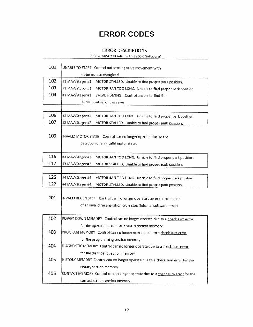
ERROR CODES

13

14
Troubleshooting
Problem: Water conditioner fails to regenerate.
Possible Cause Solution
Power supply to MP-MCA control has been interrupted.
Determine reason for power interruption and correct. Reset time of day.
Water pressure lost. Restore water pressure.
Corrupted programming of MP-MCA timer.
Reprogram timer assembly.
Defective MP-MCA timer. Replace timer assembly.
No salt in brine tank. Add salt and regenerate.
Manual bypass valve is open. Close manual bypass valve.
Leak at riser pipe seal. Insure that riser pipe is properly sealed at o’ring seal. Inspect pipe for cracks.
Insufficient brine. Check brine float height and clean assembly if necessary. Check flow rate capabilities of safety float and air check assembly.
Plugged injector or injector screen. Inspect and clean injector and/or injector screen.
Problem: No Brine Draw
Possible Cause Solution
Plugged injector or injector screen. Inspect and clean injector and/or injector screen.
Insufficient water pressure. Increase water pressure above 25 psig (172kPa) minimum.
Corrupted programming of MP-MCA timer.
Reprogram timer assembly.
Defective MP-MCA timer. Replace timer assembly.
Obstructed drain line. Remove obstruction.

15
Problem: Insufficient brine draw
Possible Cause Solution
Partially clogged injector or injector screen.
Inspect and clean injector and/or injector screen assembly.
Restricted flow rate in brine line. Check flow rate capabilities of the safety float/aircheck assembly.
Insufficient water pressure. Increase water pressure above 25 psig (172kPa) minimum.
Excessive back pressure on injector due to elevated drain line.
Reduce drain line elevation to height of valve.
Damaged valve disk. Replace all valve disks.
Partially restricted drain line. Remove restriction.
Problem: Insufficient Refill to Brine Tank
Possible Cause Solution
Brine refill control Remove and clean
Restricted flow rate in brine line. Check flow rate capabilities of the safety float/aircheck assembly.
Problem: Excessive Water in Brine Tank
Possible Cause Solution
Plugged drain line flow control. Clean flow control.
Plugged injector and/or injector screen
Inspect and clean injector and/or screen.
Problem: Loss of Media to Drain
Possible Cause Solution
No flow control installed in drain line.
Install drain line flow control.
16
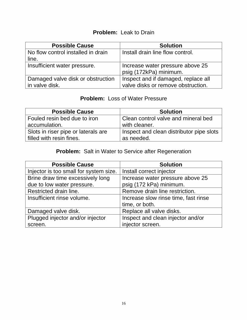
Problem: Leak to Drain
Possible Cause Solution
No flow control installed in drain line.
Install drain line flow control.
Insufficient water pressure. Increase water pressure above 25 psig (172kPa) minimum.
Damaged valve disk or obstruction in valve disk.
Inspect and if damaged, replace all valve disks or remove obstruction.
Problem: Loss of Water Pressure
Possible Cause Solution
Fouled resin bed due to iron accumulation.
Clean control valve and mineral bed with cleaner.
Slots in riser pipe or laterals are filled with resin fines.
Inspect and clean distributor pipe slots as needed.
Problem: Salt in Water to Service after Regeneration
Possible Cause Solution
Injector is too small for system size. Install correct injector
Brine draw time excessively long due to low water pressure.
Increase water pressure above 25 psig (172 kPa) minimum.
Restricted drain line. Remove drain line restriction.
Insufficient rinse volume. Increase slow rinse time, fast rinse time, or both.
Damaged valve disk. Replace all valve disks.
Plugged injector and/or injector screen.
Inspect and clean injector and/or injector screen.

17
Problem: Timer does not display time of day
Possible Cause Solution
AC Adapter unplugged Connect power
No electric power at outlet Repair outlet or use working outlet
Defective AC Adapter Replace AC Adapter
Defective PC Board Replace PC Board
Problem: Timer does not display correct time of day
Possible Cause Solution
Switched outlet Use uninterrupted outlet
Power Outage Reset time of day
Defective PC Board Replace PC Board
Problem: Control Valve regenerates at wrong time of day
Possible Cause Solution
Power Outages Reset control valve to correct time of day
Time of day not set correctly Reset to correct time of day
Time of regeneration incorrect Reset regeneration time
Problem: Control valve stalled in regeneration
Possible Cause Solution
Motor not operating Replace motor
No electric power at outlet Repair outlet or use working outlet
Defective AC adapter Replace AC adapter
Defective PC board Replace PC board
Broken drive gear or drive cap assembly
Replace drive gear or drive cap assembly
Broken piston retainer Replace piston retainer
Broken main or regenerate piston Replace main or regenerate piston

18
Problem: Control valve does not regenerate automatically when UP and DOWN buttons are held and depressed
Possible Cause Solution
AC adapter unplugged Connect AC adapter
No electric power at outlet Repair outlet or use working outlet
Broken drive gear or drive cap assembly
Replace drive gear assembly
Defective PC board Replace PC board
Problem: Control valve does not regenerate automatically but does
when UP and DOWN buttons are depressed and held
Possible Cause Solution
Defective PC board Replace PC board
Set-up error Check control valve set-up procedure

19

20

21

22

23

24
Table of Contents
Page No.
Topic Description
1
Model # and Packaging Packaging Information
Component Packaging Packaging Description
System Media Media Packaging
Anion System System Positioning
MP-MCA Control Valve Attaching Valve to Tank
2 MP-MCA Control Valve, cont’d Attaching Valve, cont’d
3 MP-MCA Control Valve, cont’d Attaching Valve, cont’d
Service & Drain Piping Drain Piping
4 Service & Drain Piping, cont’d Drain Piping, cont’d
5
System Schematic Piping Layout
System Specification Flow rates and salt usage
6 Electrical Supply Electrical Requirements
Brine Tank / Brine Tubing Brine tank w/shut off
7 Filling unit with Water Details for Filling with Water
8 MP-MCA-Control Valve Timer Setting the timer, cont’d
9 Final Check Final Installation Check
Mixing Valve Mixing Valve instructions
10 Manual Regeneration Instructions for Manual Regeneration
Power loss/ Error codes “What if” Instructions
11 Bypass Bypass Operation
12 Error Code Troubleshooting Problem/ Cause / Solution
13 Error Code Troubleshooting, cont’d Problem/ Cause / Solution, cont’d
14 Troubleshooting Problem/ Cause / Solution
15 Troubleshooting Problem/ Cause / Solution
16 Troubleshooting Problem/ Cause / Solution
17 Troubleshooting Problem/ Cause / Solution
18 Troubleshooting Problem/ Cause / Solution
19 Valve Parts List Part Numbers List
20 Valve Parts List Part Numbers List
21 Valve Parts List Part Numbers List
22 Valve Parts List Part Numbers List
23 Valve Parts List Part Numbers List
24 Warranty Warranty

MP-MCA ANION
NORMAL VIEW
NEXT
NEXT
SOFTENING
CAPACITY REMAINING
GALCHANGES
CAPACITY
REMAINING
IN GALLONS
TIME
SOFTENING PM6:35
NEXT
NEXT
0.0
CUMULATIVE
GPM
GAL
CURRENT
TIME
CURRENT
FLOW RATE
IN GALLONS
PER MINUTE
TOTAL GALLONS
SINCE START-UP*
*RESET TO “0” BY PRESSING “CLOCK” AND “REGEN” FOR 3 SECONDS
ONLY DISPLAYS IF
DAY OVERRIDE IS PROGRAMMED
OVERRIDE
REGENERATION
IN DAYS
NEXT

NEXT AND
INSTALLER SETTINGS
HARDNESSNEXT
REGEN TIME: HOUR
REGEN TIME: MINUTES
NEXT
CLOCK
SET TIME CLOCK
12:00OR
TO CHANGE TIME USE
10
2:
:00
0ff DAY OVERRIDE
(Default is OFF)NEXT

NEXT AND
REFERENCE ONLY
VALVE PROGRAMING
NEXT
NEXT
SofteningSET SYSTEM
TYPE
REGENERATION
TIME
__ x 1000
NORMAL
NEXT
CALL-off
CAPACITY
X1000
SERVICE CALL
INDICATOR
NEXT
NEXT
NEXT
NEXT
PostBRINE REFILL
TIME
BACKWASH
TIME1 8
dn 2 __BRINE & RINSE
TIME
NEXT
BACKWASH
#2 TIME3 off
NEXT
5 ___BRINE REFILL
NEXT
FAST RINSE
TIME4 8
NEXT
NEXT
RESERVE
CAPACITYAuto
NEXT
RELAY 1
RELAY 2
off
off
dnSET BRINE
TYPE
NEXT

NEXT AND
REFERENCE ONLY
VALVE PROGRAMING
NEXT
NormalSET SYSTEM
TYPE
NEXT
1VALVE SIZE
NEXT
SET 2 off
NEXT AND
Dp OFFDELTA
PRESSURE
ONLY
SET 3
NEXT
off
SET 4
NEXT
off

LOCK/UNLOCK:NEXT REGEN
(IN SEQUENCE)
REGENPRESS ONCE FOR NEXT REGEN TIME
PRESS AGAIN TO CANCEL REGENERATION
PRESS AND HOLD FOR 3 SECONDS FOR IMMED
PRESS IN REGEN TO ADVANCE TO NEXT CYCLE
MANUAL REGENERATION
LOCKING SETTINGS
AFTER SETTING A VALUE…

NEXT to EXIT
AND
AND
(3 SEC)
VALVE HISTORY
DAYS SINCE START-UP
REGENS SINCE START-UP
ERRORS SINCE START-UP
NEXT
NEXT
NEXT
NEXT
AND
DIAGNOSTICS
DAYS SINCE LAST
REGENERATION
GALLONS SINCE LAST
REGENERATION
NEXT
NEXT
NEXT
NEXT
MCA BOARD
RESERVE CAPACITY
CALCULATED PER DAY
IN GALLONS
USAGE PER DAY
IN GALLONS
MAXIMUM FLOW RATE
GPM
MAXIMUM FLOW RATE SINCE
START-UP IN GPM
GALLONS TREATED SINCE
START-UP (X1000)
NEXT to EXIT
SOFTWARE VERSION
NEXT

ERROR CODES