Embed Size (px)
Citation preview
IOM_VERSION 1.07 - 1 -
Installation and Operation of
QuikWater Heaters Each QuikWater heater is provided with its own Installation, Operations and Maintenance (IOM) Manual. This manual contains all the pertinent technical information, including dimensions and numerical values for that heater. Before proceeding with installation of the heater, this IOM manual must be read carefully. Improper installation and/or operation, or unauthorized modifications to the equipment voids the warranty and can potentially cause injury, death, or equipment damage. General information from the IOM is included in the following pages. Unauthorized use and/or reproduction of this document or the information contained herein, without express written permission of QuikWater, Inc. will render the violator subject to civil and criminal penalties.
IOM_VERSION 1.07 - 2 -
I. QUIKWATER BASIC PRINCIPLES OF OPERATION
The QuikWater heater is designed to heat water on demand, in both cyclic and continuous operation. Cold water enters the heater at the top of the tower through a control valve and is distributed through a spray nozzle(s). This control valve is opened and closed automatically by signals from level control devices located in the integral storage tank. The water flows down through the tower at the same time that hot combustion gas from the burner is rising up through the tower. The two meet, and mix, in a heat transfer zone that is filled with stainless steel thermal transfer rings. The water is heated at atmospheric pressure as the hot gas and cold water come into direct contact with each other. The hot water is accumulated in the lower integral storage tank – ready for use. The transfer / re-circulation pump provided will deliver hot water “on demand”, as needed, or continuously. The burner is turned on and off automatically depending on the water temperature in the integral storage tank and will always be on when cold water is entering the unit to be heated. The heater will maintain the “set” temperature in the integral storage tank when there is no demand and will automatically re-heat cold water in the tank if the heater has been turned off for a period of time. The heater’s control system and safety devices function together to shut off the burner/heater automatically if any abnormal operating conditions should occur that affect either safety or component life.
QUIKWATER TECHNICAL DESCRIPTION:
1. QuikWater is an atmospheric (non-pressurized) water heater. Inlet feed water pressure (regardless of source) reduces to (0) psig inside the heater.
2. QuikWater is a unique, patented design, gas fired water heater. Our customers
may select water temperatures up to 180 deg. F (82 Deg C). QuikWater’s clean burn does not adversely affect the heated water (potable in = potable out) and actually removes most volatile and semi-volatile organic chemicals.
3. Heated water is re-pressurized by the QuikWater transfer/re-circulation pump(s)
to specified design outlet pressure of typically 40 – 60 psig. If different pressures are required, they are available.
4. Heater demand (Btu/Hr) = gpm x 500 x (temp (F) out – temp (F) in). What is the
500? The 500 = 60 min/hr x 8.34 lb/gal x 1 Btu/lb – Deg F.
5. Primary fuels are natural gas and propane (oil fuel is available, but water is not potable).
6. The QuikWater dry firing chamber operates at approximately 2200 deg. F.
IOM_VERSION 1.07 - 3 -
7. Flue gas temperatures are only 5-15 deg. F higher than the incoming water temperature.
8. All formed sheet metal surfaces are constructed out of 304L stainless steel. In
addition all water piping except valves and regulators are made out of 304L stainless steel (100% stainless steel water trains are available).
9. The QuikWater heater is a complete operating package. No external tanks or
pumps are required.
10. QuikWater’s design utilizes UL listed burners and control panels. ULC listing is available upon request.
11. All standard QuikWater motors (burner fan & water pumps) are TEFC.
12. The QuikWater’s transfer/re-circulation pump needs to run whenever the burner
is on. The water flowing inside the jacketed firing chamber is one of the heater’s safety systems. Our jacketed firing chamber absorbs heat to maintain structural integrity of the metal in the firing chamber. This re-circulation system is also used to take the water temperature readings and maintain the bottom storage tank’s temperature.
IMPORTANT
BEFORE PROCEEDING WITH INSTALLATION OF THE HEATER, PLEASE BE SURE THAT YOU HAVE READ THIS ENTIRE MANUAL. IF YOU HAVE ANY QUESTIONS, CALL THE QUIKWATER FACTORY AT 1-918-241-8880. IMPROPER INSTALLATION AND/OR OPERATION OR UNAUTHORIZED MODIFICATIONS TO THE EQUIPMENT WILL VOID THE WARRANTY AND COULD POTENTIALLY CAUSE INJURY, DEATH, OR EQUIPMENT DAMAGE. While the information in this manual is presented in good faith and believed to be accurate, QuikWater reserves the right, without notice, to alter or improve the designs or specifications of the products described herein. This information will aid in proper installation and/or operation, but reliance upon it is not to be construed as guaranteeing satisfactory results, nor is it to be construed as a warranty or guarantee, expressed or implied, regarding the performance, merchantability, fitness or any other matter with respect to the products, nor as a recommendation to use any product or process in conflict with any patent.
IOM_VERSION 1.07 - 4 -
II. CHECK LIST FOR PRE-INSTALLATION PLANNING It is highly recommended that you review this checklist with your installation
resources before attempting installation of your QuikWater unit(s).
Client Contacts: Date:
Company Name: Client Order Number:
Address: QuikWater Order Number: QuikWater Model #
Phone Number: QuikWater Local Rep: Fax Number: QuikWater Rep. Phone:
Project Planning Considerations
1. Plant environment around proposed heater location. a. Will heater component(s) be dimensionally able to enter building? Door
opening is: Height ______” Width _______” Length ______” Is the floor/pad level and ready for heater installation? Yes / No b. Utility needs for gas fired heater.
Exhaust Stack: (Order 304 SS Stack from QuikWater, Other __________) Diameter ______” Length ______” Rain Hat/Bird Screen ______” • Clean and sufficient combustion air: __________SCFM
Does room have inlet air opening(s)? Yes / No If room is at negative pressure, is ducting to an outside location ready? Yes / No
NOTE: If the air is dusty, or has airborne particles, or if chemicals are present, the heater should use only outside air ducted to the burner air inlet.
• Tank overflow provisions to drain? Yes / No • Vacuum breaker on the overflow line? Yes / No • Fuel supply and vents:
Natural Gas ________ SCFM@ ________psig or ________”w.c. (and/or) Propane Vapor ________SCFM @ psig Propane Vaporizer? Yes / No
NOTE: All gas regulator vents and/or vent lines should exhaust to a
non-hazardous location.
• Water Supply ________ GPM @ ________psig @ ________°F; Water Meter _______ Line Diameter ________” Full port block valve _______ Water Strainer ________
IOM_VERSION 1.07 - 5 -
• Hot Water Discharge: Line Diameter ________” Full port block valve ________, By-pass provision ________, (or) supply loop back to tank ________.
• Electrical power Volts_______ Phase_______ Hertz ________ Proper Ground ________
• Compressed Air Pressure ________ Line size to unit ________ SCFM available________
2. Your company’s insurance and training requirements?
• Fuel Train Approval (UL, FM, IRI) • Seismic Considerations ___________________________________________
• Overall Approval (ETL, __________________)
• Training for Operating Personnel _____________
3. Labor and Equipment?
• Schedule Your Installing Personnel And / Or Mechanical Contractor. Proposed Date: ___________________ • Schedule QuikWater Factor / Rep Personnel for Start-up Assistant.
Proposed Date: __________________
• Heater Delivery Proposed Date: __________________ 24 Hour Call Notice: ______________ Truck Unloading and heater positioning equipment (Crane, Forklift, Personnel, and Spreader Bar): _______________ Temporary Storage: ____________
• Enter Spare Parts Order to Arrive for Proposed Start-up Date:
4. Heater Delivery to Job Site.
• Freight Terms: FOB Sand Springs, Oklahoma. • Freight Charges: COD ________, Prepay and add ________
All heaters are shipped at buyer’s risk. Any claims for damage should be made immediately with Transportation Company by noting on the freight bill of lading.
• Verify receipt of all items on the bill of lading before signing.

IOM_VERSION 1.07 - 6 -
5. Your Hot Water Piping System (QuikWater Recommendations) • If deadhead delivery system (no return loop), QuikWater supplies a by-pass leg
to protect supply pump(s). Required components include: full port manual valve and a pressure reducing valve or alternate equivalent ________________.
• If hot water piping loops, QuikWater can provide additional return piping
connections to heater tank ______________.
6. Post Start-Up Items: • Tank Insulation – 1” Thick Fiberglass • Operation Training
________________________________________________________________________________________________________________________________
IOM_VERSION 1.07 - 7 -
III. GENERAL INSTALLATION
A. LOCAL CODES AND REGULATIONS
Check local codes and regulations before proceeding. The information in this manual is general in nature and is not intended to supercede any governing local, state or provincial regulations, nor guarantee compliance to local codes or regulations. It is recommended that the user consult with their insurance carrier to ensure that the heater meets insurance requirements.
B. RECEIVING AND UNLOADING HEATER
1. Receiving: a. Immediately, look for any obvious shipping damage, photograph
any damage for claims evidence, and note on driver’s bill of lading prior to accepting shipment.
b. Per ICC regulations, the consignee has 10 days to report any “hidden” damage to the carrier for reimbursement. A thorough inspection should be made accordingly to verify electrical control integrity, etc.
c. Immediately locate and inventory all loose shipped items: Stack sections; spare parts; flange bolting and gaskets; drain plugs; any items that may have been removed during shipment.
2. Special Guidelines:
Please read the instruction manual carefully and pass along special guidelines to the installing contractor. These QW guidelines must be followed to ensure compliance with specific installation procedures.
3. Truck Unloading:
Do NOT lift the unit at ANY time unless it has been confirmed empty (no water) and ALWAYS use spreader bar(s) for a proper lift.
C. LOCATION OF HEATER
It is the customer’s responsibility to provide a smooth level foundation adequate to support the heaters “wet” operating weight. Failure to do so can cause premature failure of metal surfaces and welds that will not be covered by warranty. A minimum of 36” clearance is recommended around the perimeter of the unit. CAUTION: Do not locate the heater near flammable or combustible materials.
IOM_VERSION 1.07 - 8 -
D. MOUNTING INSTRUCTIONS
The following procedures are specifically for NSF certified heater installations. However, following these procedures is recommended for any installation, especially in a food processing facility. 1. Mounting Instructions for NSF International Certified QuikWater
Heaters
The QuikWater unit must be sealed to the floor to prevent accumulation of water or other material beneath the equipment. Units with I-beams are supplied with kick plates to cover openings in the front and back of the skids. Before setting the unit in place, thoroughly clean the floor and the bottom of the unit. Apply a liberal bead of silicon or other watertight sealant to the outside edge of the unit where it will meet the floor. After setting the unit in place, do not slide or move without resealing. It may be necessary to apply additional sealant around the perimeter of the unit to ensure a watertight seal to the floor. Heaters that are skid mounted should be sealed as above. Then install the kick plates using at least a quarter inch bead of silicon or other watertight material to seal the kick plate to the skid and to the floor.
E. HEATER REASSEMBLY
1. Reassembly: Heater With Flanged Tower QuikWater units are shipped in two or more modular sections. The tower sections are supplied with flat face flanges for field assembly by others. All nuts, bolts and gasket materials, required to assemble the heater are included with the individual components. The heater has been factory assembled and tested using identical gasket material prior to disassembly for shipment. Each QuikWater heater is supplied with one of two types of gasket. The standard gasket is a black, Neoprene pre-formed gasket. All NSF heaters are supplied with silicone based gasket material.
a. Installation Instructions for Stainless Steel Tower Flanges Standard Heater Tower Gasket
i. Clean the flange faces. ii. Lubricate the bolts and the underside of the nuts.
IOM_VERSION 1.07 - 9 -
iii. Place a small amount of silicone sealant at each quadrant of the tower flange.
iv. Place the full face tower gasket on the lower tower flange centering the gasket bolt holes with the tower flange holes.
v. Large gaskets may come in four pieces and require reconnecting at the dovetail connection points. This can be done using a small amount of silicone to hold the connection together and prevent any leaking.
vi. Make sure that the gasket or sealant does not protrude into the vertical stack. If either sealant or gasket material protrudes into vertical stack the metal directly under the flange will burn and discolor (and possibly fail).
vii. Lower tower down guiding it into place as not to slide the gasket out of place. Do not move the tower horizontally after it has come in contact with the gasket material.
viii. Once tower is set, insert bolts and use the following bolt tightening sequence. (a) Tighten all bolts finger tight. (b) Tighten bolts on the four quadrants moving from 0º, 180º,
90º, 270º (c) Tighten bolts at 45º, 225º, 135º, 315º (d) Tighten remaining bolts in the same pattern until all bolts
are tight. (e) Starting at 0º, retighten bolts in a clockwise pattern.
NSF Heater Tower Gasket a. Clean the flange faces. b. Lubricate the bolts and the underside of the nuts. c. Place a small 1/8” bead of joint silicone sealant (for NSF
heaters, this sealant must be NSF approved) around the flange 3/8” inside the tower flange bolt circle.
d. Place the NSF approve gasket (3/4” half round Quikwater gasket material part # Q249218) on top of the silicone bead pressing it down tight against the tower flange.
e. Allow the silicone to dry until it will hold the flange gasket in place.
f. Make sure that the gasket or sealant does not protrude into the vertical stack. If either sealant or gasket material protrudes into vertical stack the metal directly under the flange will burn and discolor (and possibly fail).
g. Lower tower down guiding it into place as not to slide the gasket out of place. Do not move the tower horizontally after it has come in contact with the gasket material.
h. Once tower is set, insert bolts and use the following bolt tightening sequence.
i. Tighten all bolts finger tight. j. Tighten bolts on the four quadrants moving from 0º, 180º,
90º, 270º
IOM_VERSION 1.07 - 10 -
k. Tighten bolts at 45º, 225º, 135º, 315º l. Tighten remaining bolts in the same pattern until all bolts
are tight. m. Starting at 0º, retighten bolts in a clockwise pattern.
F. CUSTOMER UTILITY CONNECTIONS
Exhaust stack, fuel and water piping, water tank overflow and electrical conduit should be self-supporting. The heater or heater components should not be used to support any line connections. NOTE: Refer to the on-site utility hook ups specification sheet in the appendix for connection assistance.
1. COMBUSTION AIR SUPPLY
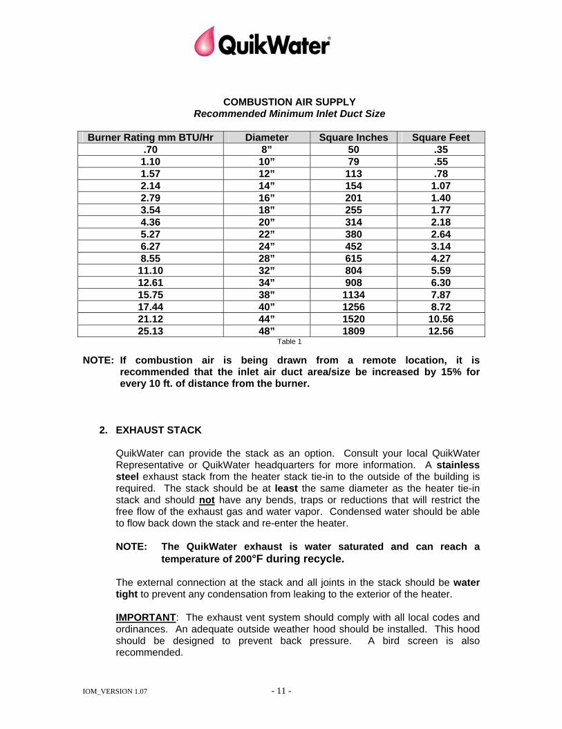
The burner/blower requires approximately 240-300 SCFM (standard cubic feet per minute) of combustion air per million BTU/HR of burner rating. Ventilation provisions must provide for adequate air flow to the blower with negligible pressure loss. An air intake opening of at least one-half square foot (72 sq. in.) per million BTU/HR of burner rating is recommended (see Table 1 below). Combustion air quality should generally be suitable for breathing and dust free. If needed, air filters with an area of approximately one square foot (144 sq. in.) per million BTU/HR of burner rating are available and should be installed on the air intake. CAUTION: Do not store combustible or flammable materials near the combustion air duct intake.
IOM_VERSION 1.07 - 11 -
COMBUSTION AIR SUPPLY
Recommended Minimum Inlet Duct Size
Burner Rating mm BTU/Hr Diameter Square Inches Square Feet .70 8” 50 .35
1.10 10” 79 .55 1.57 12” 113 .78 2.14 14” 154 1.07 2.79 16” 201 1.40 3.54 18” 255 1.77 4.36 20” 314 2.18 5.27 22” 380 2.64 6.27 24” 452 3.14 8.55 28” 615 4.27
11.10 32” 804 5.59 12.61 34” 908 6.30 15.75 38” 1134 7.87 17.44 40” 1256 8.72 21.12 44” 1520 10.56 25.13 48” 1809 12.56
Table 1
NOTE: If combustion air is being drawn from a remote location, it is recommended that the inlet air duct area/size be increased by 15% for every 10 ft. of distance from the burner.
2. EXHAUST STACK
QuikWater can provide the stack as an option. Consult your local QuikWater Representative or QuikWater headquarters for more information. A stainless steel exhaust stack from the heater stack tie-in to the outside of the building is required. The stack should be at least the same diameter as the heater tie-in stack and should not have any bends, traps or reductions that will restrict the free flow of the exhaust gas and water vapor. Condensed water should be able to flow back down the stack and re-enter the heater. NOTE: The QuikWater exhaust is water saturated and can reach a
temperature of 200°F during recycle. The external connection at the stack and all joints in the stack should be water tight to prevent any condensation from leaking to the exterior of the heater. IMPORTANT: The exhaust vent system should comply with all local codes and ordinances. An adequate outside weather hood should be installed. This hood should be designed to prevent back pressure. A bird screen is also recommended.
IOM_VERSION 1.07 - 12 -
CAUTION: If the stack is not properly installed, excessive back pressure can cause burner “stalling” to occur. In this case, the burner will not operate correctly and may shut down automatically. NSF NOTE: The following procedures are specifically for NSF certified heater installations. However, following these procedures is recommended for any installation, especially in a food processing facility. Installing Stack Extensions Stack extensions should extend at least five feet above the roof opening. Stack extensions shall be watertight and made from 304 stainless steel. Fabricating and Installing a Rain Hat Compliance with NSF International Standard No. 5 requires installation of a rain hat. A rain hat prevents precipitation and foreign objects from entering the heater stack. NSF certified heaters installed by QuikWater include the rain hat and installation. For heaters installed by others, attach the rain hat securely using sheet metal screws or spot welds. Please contact your QuikWater representative for additional information concerning alternate rain hat configurations or to purchase a QuikWater rain hat.
3. WATER
Inlet water may contain dirt, sand and other debris which may damage the heater, pumps and other components. Damaging foreign materials should be removed from the water before being introduced into the heater. A strainer is recommended and a filter may also be required depending on quality of the water. Other water quality considerations are hardness (expressed as CaCO3) and chloride content. Hard water will tend to produce scale or calcium build up on the internal parts of the heater, reducing efficiency. In extreme cases, the heater may be significantly damaged if the calcium deposits are allowed to build up so that flow within the heater is restricted. QuikWater provides a suggested preventative maintenance program that will keep your heater operating in top form which is included in this manual. The heater may require monitoring for calcium build-up until the optimum maintenance program is discovered to control calcium buildup. Please refer to our heater maintenance section of the IOM Manual for instructions on monitoring and cleaning of the unit. Chlorides, salts or any other chloride chemical compound can destroy 304/304L/316 stainless materials. If a QuikWater heater is to be operated in a closed loop capacity, capability to perform blow down procedures will be needed. Under certain circumstances, stainless steel may be susceptible to preferential corrosion attack. The presence of chlorides in either an open loop or circulating system must be addressed. These conditions will void your warranty if it results in deterioration of the stainless steel vessel.
IOM_VERSION 1.07 - 13 -
If the quality of supply water is questionable, seek assistance from a qualified water treatment specialist. While the QuikWater heater is a relatively low maintenance piece of equipment, it does require some periodic maintenance. If a continuous supply of water to the process is required a parallel cold water by-pass line should be installed. The line should have a manual valve at the point of connection with the hot water discharge line from the heater, to enable the heater to be isolated and/or taken out of service temporarily. (An automatic cold water bypass system is available as an option).
4. INLET WATER CONNECTION
The inlet cold water supply line(s) should be at least as large (same diameter) as the inlet water connection, provided near the top of the heater. NOTE: A minimum “flowing” water pressure (see specification sheet in
appendix) is required at design flow rate. Manual isolation valves (full port ball valves) are recommended on both the inlet and outlet water lines in accordance with good engineering practice, and are to be supplied by the customer.
Flush the water supply piping clean before connecting it to the heater. The heater may not function properly and may be damaged if the water supply contains dirt, debris, organic matter or other material. All heater installations should include a strainer (supplied by customer) to help prevent damage. If the water supply is not CLEAN, filtering, or treating, may be required.
5. HOT WATER DISCHARGE CONNECTION
Connect the hot water line to the water outlet connection near the pump discharge or alternate discharge connection(s), as shown on the general arrangement drawing of your heater(s) included in this manual. A check valve is recommended in the discharge hot water piping. Do NOT locate the check valve near an elbow. Connect the tank drain connection to an appropriate line or floor drain. Install a shut-off valve in this line. If desired, connect the tank overflow pipe connection to an appropriate line or floor drain. A way to break the vacuum on this drain is required so that the contents of the tank are not siphoned out. Transfer/Discharge Pumps: The QuikWater heater can be supplied with a variety of transfer/discharge pump designs depending on the application requirements. Standard Units: One single transfer/discharge pump is provided. This transfer pump will provide the heater’s design flow rate based upon an 80°F temperature rise.

IOM_VERSION 1.07 - 14 -
Custom Units: All models can be built with 1, 2, or more pumps and are built to design for the customer’s application.
Options a. Alternate flow rates and discharge pressures to meet special requirements. b. Multiple pumps providing various flow rates and pressures. The multiple
pumps can be manually started and stopped, by using switches on the control panel, or automatically started and stopped by pressure or flow switches. The discharge connections of the multiple pumps can either be piped separately or combined in a “manifold” with a single connection.
See Controls and Control System Design section in Appendix for heater-
specific information. 6. FUEL CONNECTION
Purge any air from the fuel line(s) before connecting to the heater. After the fuel piping has been connected, pressurize the gas train and check all joints, with a test solution or soapy water, for leaks. The fuel supply line(s) to the heater should be at least as large as the inlet gas connection(s) on the gas train. Check the incoming fuel line’s normal operating pressure upstream of the inlet regulator on the heater. NOTE: The actual pressure required on the pressure gauge at the burner inlet is specified on the metal QuikWater nameplate mounted on the heater’s control panel. IF GAS PRESSURE IS TOO LOW, IT WILL RESULT IN INADEQUATE HEATING. IF GAS PRESSURE IS TOO HIGH, IT WILL RESULT IN ERRATIC OPERATION, NOISE AND PHYSICAL VIBRATION OF THE UNIT.
CAUTION:
THE MAXIMUM GAS SUPPLY PRESSURE IS INDICATED ON THE MODEL SPECIFICATION SHEET LOCATED IN THE APPENDIX OF THIS MANUAL. IF THE SITE SUPPLY PRESSURE IS HIGHER, A SEPARATE PRESSURE REGULATOR SHOULD BE INSTALLED UPSTREAM OF THE HEATER’S GAS TRAIN TO PREVENT POTENTIAL DAMAGE.
IOM_VERSION 1.07 - 15 -
7. ELECTRICAL CONNECTION
IMPORTANT: The incoming power service to the unit’s control panel should be provided with “Lightning” and surge protection to eliminate voltage “spikes” that could potentially damage the electrical controls and components. NOTE: A qualified electrician should always be used to install, service and wire the control panel.
This unit has been pre-wired for one of the following voltages:
208 VAC, 60 Hz, 3 Ph. 230 VAC, 60 Hz, 3 Ph. 460 VAC, 60 Hz, 3 Ph. 575 VAC, 60 Hz, 3 Ph.
Check the name plate on the control panel to determine the correct power to supply to your system. Systems installed in Europe may have different voltages and frequencies from those listed above. The power supply to the QuikWater control panel will need to come from a protected power source. Make sure that you follow all national, state and local codes in determining the protection for the power source for this system. All units are built to NEC standards. Modifications or additions performed after shipment without prior written approval from QuikWater may void warranty and can be dangerous. The bypassing of system safeties under any circumstance will void warranty on the unit. Connect the protected power source to the power voltage distribution block or the control panel service disconnect inside the control panel. (If you are using a “Delta” system, see the warning below.) Connect a green ground wire from your building ground to any grounding lug inside the control panel. NOTE: For “Delta” supply of 230V we recommend using one red wire for the high
voltage (230V) leg and two black wires for the low voltage (120V) legs. If your system is designed for 460 VAC and is not supplied with a control voltage transformer, you will also need to supply a protected 120 VAC supply to the control panel. Refer to the control schematic to determine where to connect the common. The neutral will need to be connected to one of the terminal blocks labeled with a “2”. The ground can be attached to any grounding lug inside the control panel. NOTE: If the system is wired for 230 volts, 3 phase, it can be converted to 460
volts, 3 phase. The electrical system can be converted by: 1) Changing the transformer wiring 2) Rewiring the blower and pump(s) motors 3) Changing the starters and heaters accordingly 4) Changing the fuse size for each power leg [Refer to the Electrical Schematic]
IOM_VERSION 1.07 - 16 -
All control circuits are 120 volt single phase and have been pre-wired accordingly.
8. INSULATION
We recommend a minimum of 1” thick fiberglass board insulation be installed ONLY on the top, bottom, ends, and sides of the integral water storage tank. Please do NOT externally insulate any non-flat surfaces as they must be free to radiate heat.
IV. HEATER COMMISSIONING (Start-up)
A. PURGING UTILITY SUPPLY LINES:
1. Cold Water Inlet(s) Hook up a temporary hose and flush to plant drain. NOTE: A water strainer or filters with differential pressure gauges
are needed to remove unwanted suspended material before connecting inlet water to your QuikWater.
2. Fuel Supply(s)
• Loosen the union closest to the pilot line regulator on the upstream side to bleed air out of the line. Retighten union and check for leaks.
3. Combustion Air Ducting (If used)
• Visually inspect interior and remove all loose debris.
4. Purging Air From the Pumps • With the tank full, loosen the vent plug or bleed line connection at the
pump. (The bleed line is a small diameter piece of rigid tubing that runs from the pump to the tank.) When no more air is coming out and a solid stream of water is flowing, retighten the connector.
B. CLEANING THE TANK:
It is imperative that the tank be free from debris before the pump(s) are turned on. After the heater is in place and all utilities have been connected, but before running the pump(s), you must clean out the tank. 1. Remove the tank drain plug. 2. Remove the access hatch cover on the top of the tank. 3. Remove any large debris. 4. Rinse out the tank with a water hose. Direct the water and any debris out the
drain. 5. Once the tank is clean, replace the drain plug and the hatch cover.
C. TIGHTEN ALL TERMINALS IN CONTROL PANEL AND ANY JUNCTION BOXES:
IOM_VERSION 1.07 - 17 -
D. ELECTRICAL MOTOR ROTATION CHECKS:
All electrical work and/or testing should be performed by a qualified electrician. Check the rotation of the pump(s) (Dry – with no water in tank) and blower as follows: 1. Place the main service disconnect switch in the “ON” position. 2. Leave the manual 120VAC on/off selector switch “OFF”. 3. With the panel door open, momentarily press the manual override button on
each motor contactor. 4. Observe the rotation of the corresponding pump(s) and blower. If the rotation
of all motors is incorrect, switch two of your incoming supply lines. NOTE: If you are running a “Delta” system, make sure that you do not move the high leg. If any one motor is rotating incorrectly, then reverse any two wires at the starter for the corresponding pump(s) and / or blower, and then recheck for proper rotation.
E. INITIAL HEATER CONTROL SETTINGS (HEATER OFF): For Honeywell Control
1. Verify hot water discharge valve closed and transfer pump has been tripped
(if the heater is a two pump design). 2. Set modulator controller (stage 1) to 105°F. 3. Set the set point controller (stage 2) to 110°F (non scalding
temperature). 4. Verify tower temperature shutdown controller is set between 190°F -
200°F. In certain cases, this controller can be set to a maximum of 210°F.
5. Verify firing chamber cooling jacket temperature shutdown controller is set between 190°F - 215°F.
For Watlow Control
1. Setup page parameter settings: press "up" and "down" arrows simultaneously for 3 seconds use the "rotating arrow" button to scroll through options
Press the "up" and "down" arrows to change parameter values Parameter: Parameter Setting: Sen RTD (sensor type) C-F F (temperature units) SdEC 0 (temperature decimal places) ISEn NO (infosense-sensor
synchronizer) SP.Lo 32 (set point low limit)
IOM_VERSION 1.07 - 18 -
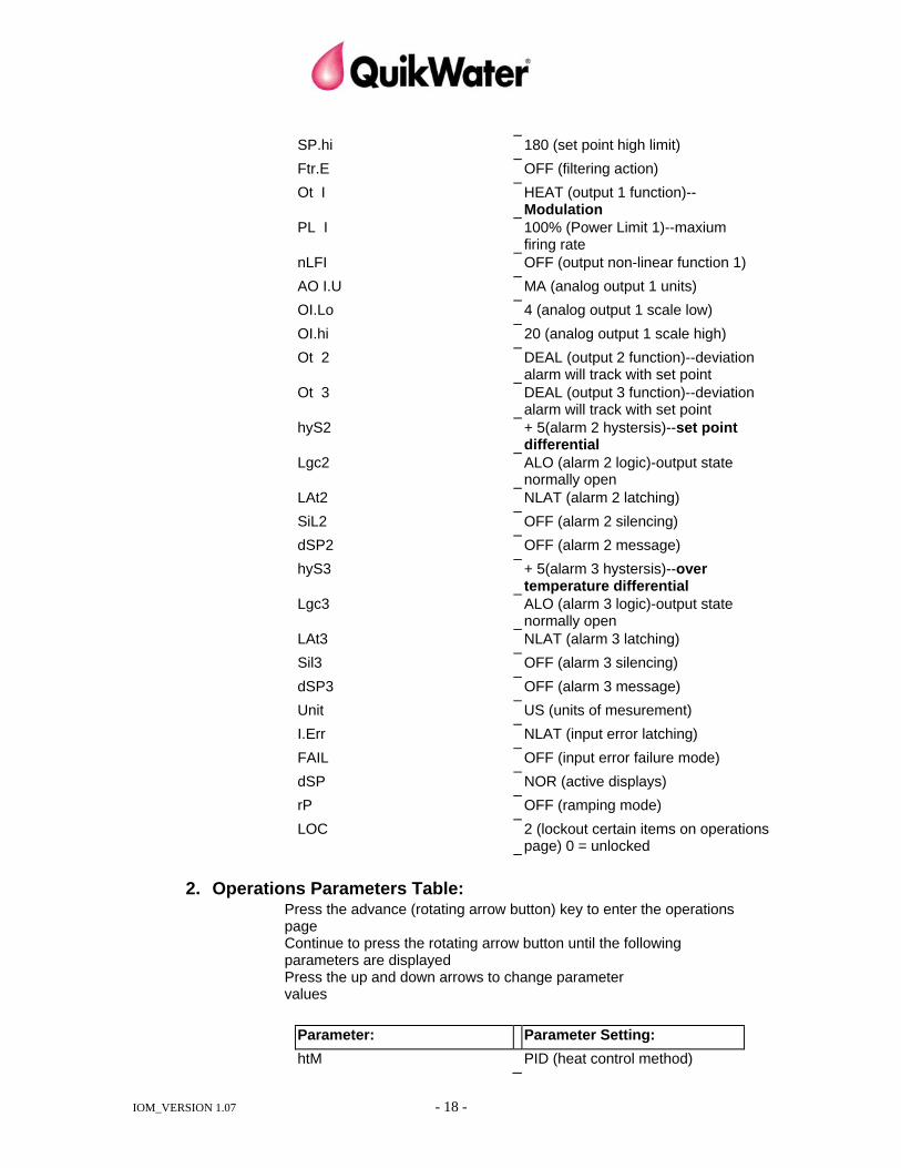
SP.hi 180 (set point high limit)
Ftr.E OFF (filtering action)
Ot I HEAT (output 1 function)--Modulation
PL I 100% (Power Limit 1)--maxium firing rate
nLFI OFF (output non-linear function 1) AO I.U MA (analog output 1 units) OI.Lo 4 (analog output 1 scale low) OI.hi 20 (analog output 1 scale high) Ot 2 DEAL (output 2 function)--deviation
alarm will track with set point Ot 3 DEAL (output 3 function)--deviation
alarm will track with set point hyS2 + 5(alarm 2 hystersis)--set point
differential Lgc2 ALO (alarm 2 logic)-output state
normally open LAt2 NLAT (alarm 2 latching) SiL2 OFF (alarm 2 silencing) dSP2 OFF (alarm 2 message) hyS3 + 5(alarm 3 hystersis)--over
temperature differential Lgc3 ALO (alarm 3 logic)-output state
normally open LAt3 NLAT (alarm 3 latching) Sil3 OFF (alarm 3 silencing) dSP3 OFF (alarm 3 message) Unit US (units of mesurement) I.Err NLAT (input error latching) FAIL OFF (input error failure mode) dSP NOR (active displays) rP OFF (ramping mode) LOC 2 (lockout certain items on operations
page) 0 = unlocked
2. Operations Parameters Table: Press the advance (rotating arrow button) key to enter the operations page
Continue to press the rotating arrow button until the following parameters are displayed
Press the up and down arrows to change parameter values
Parameter: Parameter Setting: htM PID (heat control method)
IOM_VERSION 1.07 - 19 -
Pbht 5 (Proportional band heat) Larger number - quicker response
rEht 0 (reset heat) rAht 0 (rate heat) A2hi 0 F (alarm 2 high)--burner shut
down temperature A2Lo - 200 (alarm 2 low)--not used A3hi 10 F (alarm 3 high)--shut down
temperature A3Lo -200 (alarm 3 low)--not used
3.Set points: modulation: Set so that desired output
temperature is reached
F. OPERATIONAL RUN CHECKS TO LOW FIRE (NO HOT WATER DISCHARGE):
Pre-check list • Water has been supplied and turned on to the QuikWater inlet valve. • Fuel has been connected and turned on to the QuikWater main gas line. • All motor voltages and rotations have been checked. • Low gas pressure switch has been reset. • Exhaust stack has been connected and sealed. • Cut off valve and check valve have been installed on the outgoing water line. 1. Heater On:
Turn the manual “POWER” switch to “ON”. The inlet water valve should then be energized and should “open”, starting to fill the water tank. NOTE: Adjust the isolation/control valve on the inlet water line to achieve the recommended flowing pressure shown on the Individual Specification Sheet in the Appendix of this manual, unless a flow regulator has been installed. When the water level in the tank reaches the preset operating or ”run” level, the pump(s) and blower should start unless they have been previously disabled.
2. Pilot Ignition:
After the pumps have begun to run, water flow should close the water flow switch in the re-circulation line (completing the final switch in the burner safety series line) which will then allow the blower to start. If any switch (including the call for temperature) is not closed the blower will not start. When the air pressure interlock switch senses blower output air pressure, a
IOM_VERSION 1.07 - 20 -
nominal 90 second air purge cycle is initiated. Following the purge cycle the igniter should “light” the pilot. If pilot ignition does NOT occur, the full function flame safe guard controller will “lock-out”. If this occurs, turn the 120 VAC manual switch to “OFF”, read the troubleshooting section of this manual and determine whether further purging or adjustment of the igniter is necessary. NOTE: On initial start-up, steps 1-2 may need to be repeated to allow air
to be purged from the gas line before successful ignition will occur.
2. Low Fire:
NOTE: ONLY UNITS WITH WEBSTER BURNERS START AT LOW FIRE. UNITS SUPPLIED WITH MAXON BURNERS START AT MID FIRE.
After the pilot has ignited and a flame has been proven by the ultraviolet scanner signal to the controller for 10 seconds, the main gas valve will then open.
3. High Fire:
Check the pressure gauge at the burner inlet, and compare the reading with the QuikWater Test Data Sheets. If different, adjust the gas pressure regulator to match QuikWater Test Data Sheets. NOTE: Pressure will be noted in “inches of W.C.” or PSI at the burner
manifold. A decal (approximately 3”x5”), is located on the inside door of the control panel and list this information. Additionally, a hard copy set of the TEST DATA SHEETS is located on the inside of the control panel.
4. Visual Inspection and Heater Cleaning:
Walk around the heater looking for water leaks, metal color changes, stack integrity, and note all gauge readings. The QuikWater heater is an industrial piece of equipment and was built and tested in a heavy machinery type manufacturing environment. Steps have been taken to remove oils and dirt before and after final testing. However, this product should NOT be considered to be in a “sanitary” clean condition when it left the factory, or when it arrives at its destination. If “sanitary” potable quality water is required from this heater, it will be necessary to perform some preliminary on site cleaning of the heater before normal operation. This cleaning should include at a minimum:
a. Filling, heating and draining of at least one tank of water. (This should be
done with the outlet to the system shut off to prevent anything from entering the piping system in the plant. If the heater has a separate transfer pump, the pump should be turned off during this procedure.) The heated water should then be properly disposed of outside the normal system piping – using the heater’s transfer pump or the rear drain plug.
IOM_VERSION 1.07 - 21 -
b. With the heater turned OFF, remove the tank drain plug and access hatch to the water tank. This procedure will permit thorough flushing, lighted internal inspection and complete draining of the storage tank. If further cleaning is required, use non-foaming detergents in conjunction with the above procedure as well as increasing the water temperature to at least 160°F for sanitizing purposes. Also, see Heater System Maintenance Section.
NOTE: Make sure that any chemical you use in or on the heater is compatible with all the components that it will come in contact with. Please contact your local QuikWater Agent or QuikWater headquarters with further questions.
G. FULL OPERATIONAL RUN CHECKS TO HIGH FIRE (WITH HOT WATER
DISCHARGE):
1. Hot Water / Cold Water Flow Balancing: Confirm that the hot water temperature setting (stage 2) on the temperature controller is set to 110°F. The burner will shut off automatically when the water in the tank reaches this selected “set” temperature and will restart automatically when the tank temperature drops 4-5°F below this temperature and further heating is needed. The manual isolation/control valve on the heater discharge should now be opened. As hot water is released from the tank, the water level will drop and can be monitored by watching the liquid level sight gauge. Observe the water level when the inlet water solenoid valve opens allowing fresh water into the heater. Allow the level to drop another 2-3”, then adjust the manual isolation/control valve to maintain this level (unless an outlet flow regulator has been installed). This is required to “balance” the outgoing and incoming water flow rates.
2. Purge Hot Water Piping System:
Select initial 110°F water temperature and purge safely to a drain. Then increase the temperature controller cut-off set point (stage 2) to 160°F and continue purging to drain. If heater is equipped with a modulating controller, set the modulation set point (stage 1) to 155°F.
3. Visual Inspections and Adjustments:
Use an amp meter to check amperage draw on the motors for the blower and pump(s). The correct amperage is listed on the manufacturer’s data plate. These amperages are the full load amp draw of the motor in question. The actual amperage you see should be less than or equal to this number. If the burner is out of adjustment (either too rich or too lean) the heater may “rumble” or vibrate. This “rumble” may also be caused by excessive exhaust back pressure.
NOTE: This heater was test run at the factory (700’ elevation) prior to
shipment, and adjustment of the gas pressure regulator should
IOM_VERSION 1.07 - 22 -
only be necessary if the inlet gas supply pressure or elevation is appreciably different from the gas pressure specifications indicated in the “INSTALLATION” section.
NOTE: A sample combustion gas analyzer port has been provided and
is located in the vertical tower above the flame sight glass. Combustion gas samples are VERY wet and will be about 200°F. They will have to be drawn from the sample port as there is not sufficient pressure in the tower to force them to the analyzer.
The inlet water valve [see Heater Drawing in Appendix] will close automatically when the water level in the accumulator tank reaches FULL, and will reopen when the water level has dropped to a factory-preset level due to withdrawal from the tank. [See Controls and Control System Design section in Appendix for further explanation of tank level controls].
4. Adjusting Heaters with Modulating Burner Control:
(Not applicable for units under 1,000,000 BTU’S/HR)
The following steps should be followed in setting the temperature and burner modulation controllers.
a. Set the temperature controller modulation set point (stage 1) 2-4 degrees
lower than the desired cut-off set point. This is a starting point, if water temperature control is not as you desire this modulation set point can be moved to any value less than or equal to the temperature cut off position.
b. Set the throttling range. The throttling range determines the upper and lower temperature limits between which the burner will modulate between low and high fire. The default setting is 02. (For example: If the throttling range is set at 06, then the burner will be at the high fire position if the temperature drops 3 degrees or more below the modulation set point. The burner will be at the low fire position if the temperature rises 3 degrees or more above the modulation set point.)
c. Set the temperature controller cut-off set point (stage 2) to the desired outlet water temperature.
d. Set the differential. The differential determines how many degrees that the tank temperature will drop before the burner is brought back on. The default setting is 02.
e. Allow the heater water tank to fill and also let any external tanks to fill with hot water.
f. As the water temperature increases to the modulation set point the burner will automatically throttle back to a lower firing position to control the overshoot of the final required water temperature.
g. If the water temperature in the tank(s) meets your requirements then the settings can be left alone at this point.
h. Record these settings, and RETURN to them if they have been changed. i. Repeat these steps for any other desired temperature that you want to
run at for an extended period of time.
IOM_VERSION 1.07 - 23 -
These steps will create the ideal separation between the temperature and modulator control set points and should smooth out the burner operation. You will always want to set both control points to these “combination” settings whenever you change the water temperature.
Twin Tower Heaters QuikWaterTwin Tower heaters are typically supplied with two temperature controllers. One is used to control the cut-off set point for the lead burner and the modulation for burner 1. The other is used to control the cut-off set point for the lag burner and the modulation for burner 2.
a. Set the lead controller modulation set point (stage 1) 2-4 degrees lower
than the desired cut-off set point. b. Set the throttling range. The throttling range determines the upper and
lower temperature limits between which the burner will modulate between low and high fire. The default setting is 02. (For example: If the throttling range is set at 06, then the burner will be at the high fire position if the temperature drops 3 degrees or more below the modulation set point. The burner will be at the low fire position if the temperature rises 3 degrees or more above the modulation set point.)
c. Set the lead controller cut-off set point (stage 2) to the desired temperature.
d. Set the differential. The differential determines how many degrees that the tank temperature will drop before the burner is brought back on. The default setting is 02.
e. Set the lag controller modulation set point (stage 1) the same as the lead controller modulation set point.
f. Set the throttling range. The throttling range determines the upper and lower temperature limits between which the burner will modulate between low and high fire. The default setting is 02. This setting should be the same as the lead controller throttling range.
g. Set the lag controller cut-off set point (stage 2) to the desired temperature. This setting should be the same as the lead controller cut-off set point.
h. Set the differential. The differential determines how many degrees that the tank temperature will drop before the burner is brought back on. The default setting is 02. This setting should be set a few degrees higher than the lead controller differential. This will cause the lag burner to only come on if the lead burner is not keeping up. Once it is on, it will stay on until the desired cut-off temperature is reached. (For example: Assume that the lead controller cut-off set point is 140, the lead differential is 02, the lag controller cut-off set point is 140 and the lag differential is 04. If the tank temperature drops to 138 (140-02), the lead burner will come on. If the temperature continues to drop and reaches 136 (140-04), then the lag burner will also come on. Both burners will remain on until the temperature reaches 140.)
H. VERIFY SAFETY INTERLOCK SHUTDOWNS (HEATER ON):
IOM_VERSION 1.07 - 24 -
1. High Temperature Shut-Down On Tower and Firing Chamber (HTSD):
At least one high temperature shut-down switch [see heater drawing in Appendix] protects the unit from overheating and damage by turning the burner “off” when the temperature in the heater tower exceeds a preset temperature (approximately 190°F on tower and 215°F on chamber). NOTE: If the high temperature shut down “trips”, it must be manually
reset by pressing the RED reset button on the switch. CAUTION: This should be done only after determining the cause of the problem.
2. Low Water Level:
If the hot water flow from the tank is greater than the incoming supply flow (the maximum design flow), eventually the low water level switch will shut the burner and pumps “off” until the water level in the tank rises sufficiently for normal operation. The tank has been sized to allow some imbalance in incoming and discharge flow rates to accommodate temporary peak demands.
3. Re-circulation Water Flow/Pressure Switch:
Either a water flow or pressure switch [see heater drawing in Appendix] provides additional protection against overheating and lack of circulation (flow). It is located either in the re-circulation water line between the firing chamber and the heater tower or directly under the firing chamber in the re-circulation line. If this switch senses too low water pressure/flow or on some sizes too high a water pressure, the burner will shut “off” until adequate pressure (flow) is restored. This switch has been preset at the factory and should be adjusted only by a qualified service person.
4. High and Low Gas Pressure Switches: Certain size heaters are provided with high and low gas pressure switches as required by various codes. If either of the switches detects abnormal gas pressure, they will “trip” causing the burner to shut off. These switches require a manual reset. CAUTION: This should be done only after determining the cause of the problem.
5. Air Pressure: An air pressure switch is provided on all heaters. If the burner/blower motor should malfunction or be spinning in the wrong direction, a loss of forced combustion air will cause the fuel to be shut off.
V. HEATER SYSTEM MAINTENANCE
A. FIRST 30 DAYS AND BI-ANNUAL INSPECTIONS
1. Test the water quality before and after the heater. Measure and record the following:

IOM_VERSION 1.07 - 25 -
• Chloride level - If the chloride level exceeds 50 ppm at any time, contact QuikWater immediately to discuss possible solutions to the problem. High chloride levels can seriously impact the life of your heater.
• Hardness - If the hardness level increases, you should increase the frequency of cleanings.
• pH - There may be a slight drop in pH through the heater. This is normal. Watch for changes over time.
Note any changes in the levels over time. Note any differences between the inlet and outlet water. Periodic blow-down of the system may be required in order to keep the above levels within acceptable limits. See the “Customer Utility Connections” section of this manual for additional information on water quality.
2. Visual Internal Inspection
A visual inspection of the heater internals within 30 days of startup is recommended. Look for evidence of calcium deposits which indicate that water hardness is higher than recommendations. Proper removal of build up and deposits is critical to the extended life and performance of the heater. This inspection should be initially repeated on a monthly basis and then as needed thereafter.
a. Electrical Power Off
Turn “off” the heater and be certain the main electrical disconnect switch is also “off”.
b. Lower Tower Access Panel Remove the lower access panel (port) on the vertical heater tower. Inspect the 304 stainless steel packing rings on the bottom for cleanliness. Remove some of the packing rings closest to the access port. This will allow you to examine the packing ring closest to the center of the tower. Build up may not be evident at the perimeter of the tower, but may be present toward the center. Any scale build up on the rings should be analyzed for its content, and the amount of build up should be noted by the individual(s) responsible for equipment maintenance. This build up will adversely affect your heater’s capacity. Once it becomes so severe as to significantly slow the flow of water down through the tower and slow the exit of the exhaust gases metal overheating and failure can occur. Early inspection should serve as a benchmark for scheduling routine cleaning cycles and future inspections. The packing should be inspected and maintained frequently enough to keep it in clean condition for optimum performance. (See specific maintenance information also found in this manual for a more detailed discussion of how to check for build up).
c. Upper Tower Access Panel
Remove the upper access panel (port) on the vertical heater tower. Inspect the bottom side of the mist eliminator (mesh pad) located below the stack opening. Any build up should be analyzed for its content, and the amount of build up should be noted by the individual(s) responsible
IOM_VERSION 1.07 - 26 -
for equipment maintenance. The heater efficiency may also be adversely affected by this build up if it becomes severe enough to restrict the flow of exhaust gases from the heater. Early inspection should serve as a benchmark for scheduling routine cleaning cycles and future inspections.
d. Mist Eliminator The mist eliminator should be maintained frequently enough to keep it in clean condition. The mist eliminator is loose and can be “fished” out of the stack opening for additional cleaning through the upper access port.
e. Firing Chamber
i. Remove the tower mounted flame sight glass assembly and, using a flashlight, observe the inner wall of the firing chamber for evidence of any build up or deposits. If there is build up of lime scale inside the firing chamber, an internal cleaning may be required. To gain physical access to this area you will need to either enter through the tank access port or remove the burner.
ii. Open the small inspection opening provided on the outer wall of the horizontal firing chamber and visually inspect for evidence of sediment inside the water
f. Water Tank Access Cover Remove and clean out access cover, on the top of the integral water
storage tank, and visually check for evidence of unusual sediment in the bottom. Should sediment be found, it should be analyzed to determine what it is. Appropriate steps can then be taken to reduce or eliminate it. This inspection should determine the interval of future inspections.
g. Water Tank Level Sensors QuikWater uses two different types of level sensors in the water tanks.
Determine which type your system has and follow the corresponding instructions. i. Level Probes Locate the blue level controller on top of the water tank. Remove the
access cover. Note the wire colors to the “A, B, C and D” labeled probes. Disconnect only the “A” probe wire. Then, use a 13/16” diameter deep well socket to loosen and vertically remove the “A” probe assembly. Inspect the lower brass rod for scale build up. Use emery paper to clean the brass rod for scale build up. Reinstall it as you found it. Repeat this sequence for each remaining probe.
ii. Float Switches The float switches are installed in the side wall of the tank. The
switches are protected by a control box enclosure. Remove the cover. Using a marker or grease pen, mark the top center of each switch. Put a matching mark on the tank wall. This will assure that the level switches are reinstalled properly. Disconnect the wires from one switch. Unscrew the switch from the tank. Inspect for scale build-up or any other debris. Clean off the switch and make sure that the float freely travels up and down. Apply Teflon tape and/or “pipe dope” to the threads. Reinstall the switch. Make sure that the marks
IOM_VERSION 1.07 - 27 -
line up. Reconnect the wiring. Repeat this procedure for each switch. Replace the cover.
3. Igniter Inspection
QuikWater uses different types of burners. On some burners (primarily Maxon), the igniter is mounted on the outside. On other burners (primarily Webster), the igniter is housed inside the pilot assembly cover. Determine which setup your heater has and follow the corresponding instructions. Before inspecting the igniter make sure that you have a replacement. The ceramic of the igniter is delicate and will crack easily. If the ceramic cracks the igniter will no longer work.
B. RECOMMENDED MAINTENANCE PROCEDURES:
By utilizing the inspection findings, (item A. above) maintenance determinations can be made regarding the following: 1. Replacement of wearing parts, operational control adjustments and misc. 2. Internal heater cleaning, with acidic chemicals, to remove lime scale. When
above visual internal inspections reveal lime scale from hard water, QuikWater recommends the following cleaning procedures:
a. Close the hot water discharge block valve to retain all water and cleaning chemicals on board the heater. Heat a full tank of water to 120°F - 160°F. Then turn off the fuel supply so the burner can not re-light.
b. Acidize the heater’s water to remove lime deposits.
NOTE: Use only Sulfamic or Citric Acid in your heater. Consult your chemical supplier for proper concentrations and instructions.
VI. TROUBLE SHOOTING – HEATER SHUTDOWNS
SYMPTOM POSSIBLE CAUSE
IOM_VERSION 1.07 - 28 -
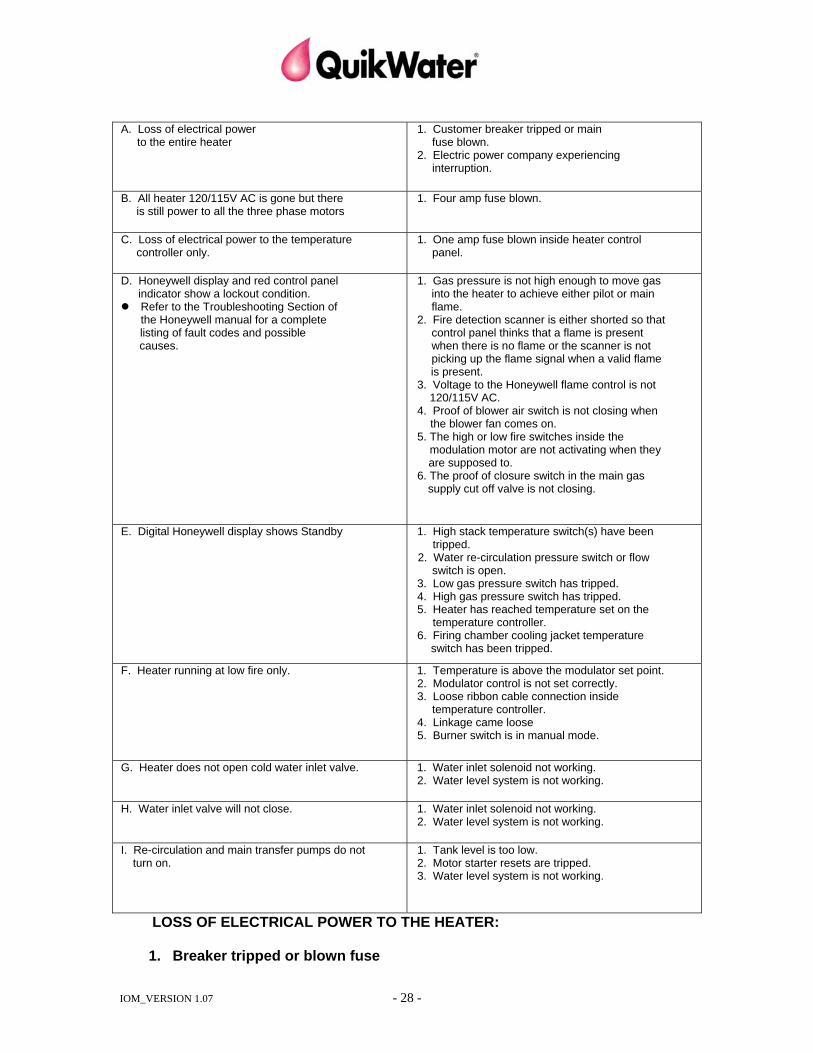
A. Loss of electrical power to the entire heater
1. Customer breaker tripped or main fuse blown.
2. Electric power company experiencing interruption.
B. All heater 120/115V AC is gone but there
is still power to all the three phase motors 1. Four amp fuse blown.
C. Loss of electrical power to the temperature controller only.
1. One amp fuse blown inside heater control panel.
D. Honeywell display and red control panel indicator show a lockout condition. Refer to the Troubleshooting Section of
the Honeywell manual for a complete listing of fault codes and possible causes.
1. Gas pressure is not high enough to move gas into the heater to achieve either pilot or main flame.
2. Fire detection scanner is either shorted so that control panel thinks that a flame is present when there is no flame or the scanner is not picking up the flame signal when a valid flame is present.
3. Voltage to the Honeywell flame control is not 120/115V AC.
4. Proof of blower air switch is not closing when the blower fan comes on.
5. The high or low fire switches inside the modulation motor are not activating when they are supposed to.
6. The proof of closure switch in the main gas supply cut off valve is not closing.
E. Digital Honeywell display shows Standby 1. High stack temperature switch(s) have been tripped.
2. Water re-circulation pressure switch or flow switch is open.
3. Low gas pressure switch has tripped. 4. High gas pressure switch has tripped. 5. Heater has reached temperature set on the
temperature controller. 6. Firing chamber cooling jacket temperature
switch has been tripped.
F. Heater running at low fire only. 1. Temperature is above the modulator set point. 2. Modulator control is not set correctly. 3. Loose ribbon cable connection inside
temperature controller. 4. Linkage came loose 5. Burner switch is in manual mode.
G. Heater does not open cold water inlet valve. 1. Water inlet solenoid not working. 2. Water level system is not working.
H. Water inlet valve will not close. 1. Water inlet solenoid not working. 2. Water level system is not working.
I. Re-circulation and main transfer pumps do not turn on.
1. Tank level is too low. 2. Motor starter resets are tripped. 3. Water level system is not working.
LOSS OF ELECTRICAL POWER TO THE HEATER:
1. Breaker tripped or blown fuse
IOM_VERSION 1.07 - 29 -
Corrective Actions a) WARNING cut off all power before checking fuses. Remove the fuses one at a time and check continuity with a multi-meter. If a
bad fuse is found replace it. If all fuses are good, then go to b. b) If no bad fuses are found, trace back voltages to customer’s main power
supply box and correct problem there.
2. Electric Power Company experiencing interruption or high/low conditions (e.g., brown out, etc.). Corrective Actions Contact local power company.
A. 120/115V AC OUT ONLY
There is a four (could be higher amperage depending on exact heater model) amp fuse inside the heater control panel that all 120V AC power feeds through. Turn off the main disconnect and the 120V AC control switch, then open the control panel. a) Find the four amp fuse, (The fuse could be outside the panel box on the add-on
transformer found on some Webster burners) remove from the fuse holder and test with a multi-meter. If the fuse is bad, replace it. If the fuse is good go to (b).
b) Examine the 120/115V AC transformer (if your unit has a transformer) if 120/115V is present on the output lugs, then transformer is ok and there is a break in the wiring; or the four amp fuse does not work when power is applied to it. If 115 volts is not present use your multi-meter to check for proper input voltages (460/380/575V AC). If voltage is present, replace the transformer. If supply voltage is not present check all supply fuses and breakers. WARNING cut off all power before checking these fuses. If any bad fuses are found, replace the bad fuse. If no bad fuses are found, trace customer’s power supply until you find the problem.
c) If a dedicated 120/115V AC wire was pulled by an electrician when the heater was first installed, use a multi-meter to see if 120/115v AC is present on the 120V lug on the top of the top of the control panel board. If 120/115V is not present then trace back voltages to customer’s main power supply box and correct problem there. If 120/115V AC is present, then there is a break in the wiring or the four amp fuse does not work when power is applied to it.
B. NO POWER TO TEMPERATURE CONTROLLER ONLY
There is a one amp fuse that feeds power to the temperature controller. Turn off the main disconnect and the 120V AC control switch. Then open up the control panel. Pull the one amp fuse and check for continuity using a multi-meter. If the fuse is bad, replace it. If the fuse is good, check for a break in the wiring that feeds power to the temperature controller.

IOM_VERSION 1.07 - 30 -
C. LOCK-OUTS:
NOTE: In the event of a red panel light indicating “lock-out” and/or the Honeywell display shows a lock out, it will require manual reset of the Primary Honeywell Controller to restart the heater.
NOTE: The number of the “Lock-out” code is needed to refer to the Honeywell manual for a complete list of “Lock-out” code explanations. The test description does not tell you the cause of failure only what the controller was doing last when the lockout occurred.
D. LOCK-OUT PROBLEMS:
The QuikWater heater will go into the lockout mode, with the red panel light on indicating a lock-out, when any of the following problems occur: 1. Failure to achieve pilot (Fault 16 or 28)
a) The first thing to do is reset the heater and then look in the rear sight glass located in the back vertical portion of your heater (farthest away from the burner). If you see orange flashed but no flame, skip to step f. If you see a small flame that is lit but is not constant (light winking on and off, the control panel display shows the 5.0v indicator to not be constant) skip to step (x). If you do not see any easily identifiable light when the heater calls for the pilot flame to start, proceed to step b.
b) You are not getting a good spark (or any spark at all). The probable cause for this is the igniter is wet or broken or might be positioned incorrectly inside the burner. Turn off all power to the heater. Take a black magic marker and put a black line on the white ceramic portion of the igniter so you can replace the igniter to the original depth. After having marked the igniter remove the rubber boot that connects to the igniter rod (like a spark plug wire on your car). Loosen the thin jam nut that is used to tighten the igniter in place and remove the igniter from the burner. Examine the igniter rod to see if it is wet or if the steel part of the igniter tip is burned off. Also check to see if any of the white ceramic material is broken or cracked. If the igniter is wet, dry off and place back into the heater. Try to start the heater again, also contact the factory for help. If the steel tip is burned off or the ceramic material is broken or cracked you will need to replace the igniter.
c) If everything looks ok, check the position of the igniter inside the burner. i. External Igniter The best way to do this requires two people. You will need to remove
the rear sight port that you were looking through earlier and then shine a pen flashlight into the heater while a second person inserts the igniter into the burner. As the igniter is inserted you will eventually be able to see the igniter tip inside the burner chamber. Move the igniter back until you can no longer see the igniter tip from the rear sight glass and lock the igniter into place. (DO NOT OVERTIGHTEN THE LOCKING NUT. YOU WILL BREAK THE CERAMIC MATERIAL IF YOU DO). Put the spark plug boot back on the igniter, mark the new depth location with a magic marker on the ceramic and replace the sight glass at the rear of the heater and try to restart the heater. If you get a strong pilot then you are finished.
IOM_VERSION 1.07 - 31 -
ii. Internal Igniter Remove the pilot assembly cover. Carefully pull the assembly out of the burner. This assembly will only come out a few inches. At this point, remove the wire from the igniter and unscrew the UV scanner (some burners have the UV scanner mounted separately). Pull out entire assembly. The igniter should be mounted with the bent tip lining up with the notch in the pilot diffuser. Remove and clean the igniter. Use emery cloth to clean all metal parts. Replace if the insulation material is cracked or broken. Insert the assembly into the burner. Screw in the UV scanner. Tighten only finger tight. Replace the wire on the igniter. Reassemble the pilot assembly.
d) If you still can not see any spark when you look through the rear sight glass, then you need to see if the transformer is actually sending a spark out to the igniter.
CAUTION: THIS NEXT STEP CAN BE DANGEROUS!!!!! e) Remove the igniter from the burner. f) Close the manual ball valves that are on the pilot and the main gas lines (IF
YOU DON’T KNOW WHERE THESE ARE OR HOW TO DO THIS, DO NOT PROCEED).
g) Use a pair of good insulated pliers to hold the igniter rod so that the steel tip of the rod is about ¼ inch away from the metal surface on the outside of the burner. Hold the igniter by the ceramic part. Connect the spark plug boot back on the igniter. Start up the heater and let the heater try and achieve pilot. When the heater asks for the pilot to light, you should get a strong electrical spark to arc to the steel frame of the burner. The heater will continue to send spark to the igniter for ten seconds. After the unit has stopped sparking, the heater will be in lockout mode. Put the igniter back in place noting the magic marker line you made earlier. Turn the pilot and main gas lines back on and try to restart the heater.
h) If you did not see any spark after the heater went from start up to lock out mode, you need to check the transformer operation. Look at the wiring diagram for your heater found inside the door of the control panel. Find the terminal block that sends out the 115/120v AC signal to the transformer. Reset the heater to let it go through another cycle. Use a multi-meter to measure that 115/120v AC is present when the heater asks for the pilot to light. If voltage is shown at the right times then either the wires that feed your transformer are broken or your transformer needs to be replaced. If 115/120v AC is not seen then your Honeywell flame safeguard (blue box inside the panel) may be bad and need to be replaced. If you do all of this and your igniter still does not spark, call the factory.
i) Make sure that you have gas pressure on the pilot line. Check for any closed valves on your incoming gas lines or on the heater's main gas or pilot lines. Check your supply gas meter for pressure if possible. If no problem found, go to the next step.
j) With the heater main disconnect turned off, crack the union on the pilot line that is before the solenoid valve and see if you get a gas smell when this
IOM_VERSION 1.07 - 32 -
union is loosened (you do not need to completely remove this union). If gas is present, go to the next step.
k) Turn power back on to the heater. Let the heater go through its purge cycle and put your hand on the pilot line solenoid valve. When the heater asks for the pilot flame to start you should feel (and hear) a click inside this pilot solenoid. If everything looks ok, go to the next step.
l) If you have seen spark when you look in the back of the sight glass and you have checked for gas going into the pilot and still can not get a pilot flame, check the motor rotation of the blower motor. If the motor is not turning the right direction, then you need to check all other motor rotations on the pumps to see if they are moving in the right direction. If only the fan motor is spinning in the wrong direction, then change the wiring at the motor, or the corresponding motor starter, to reverse direction of the rotation. If all motors are spinning in the wrong rotation, change the three phase wiring in the control panel to correct all motor rotations at the same time.
m) If you still can not achieve pilot, call the factory.
2. Pilot starts but not the main flame. (Fault 19) a) Make sure that the manual ball valve on the main gas line is open. If it is
open, then go to b. b) When the heater calls for the main flame to start, look at the pressure gauge
that is close to the burner and see what the gas pressure is when the main gas valve(s) open.
c) Note at what point the lockout occurs. There is a 10 second time in which the pilot valve is open at the same time as the main gas valve. If lockout occurs here then typically your main (after the QuikWater pressure regulator) gas pressure to the burner is too high. If however the failure occurs between 10-15 seconds then the gas pressure to the burner on the main line (after the QuikWater pressure regulator) is too low.
3. Voltage to the Primary Honeywell Controller drops below 115 volts.
a) Open panel door to the QuikWater heater control box and check incoming main voltage to service/disconnect. Voltage options (see heater specification) include: 120v, 208v, 230v, 460v, and 575v. Some heater control panels will have a step-down transformer for 230v and higher, located on the outside of the QuikWater heater control panel. Locate the step-down transformer leads inside the QuikWater control panel. Check line voltage, with a multi-tester, looking for 120/115v, replace the transformer.
b) The 120 VAC on the dedicated control voltage line (no transformer) is low. This caused by poor ground at the main junction box the 120 VAC line is drawn from, too small a wire has been used to bring the 120 VAC to the QuikWater box, or there is a problem with voltage from the city.
4. Low or inadequate electrical signal coming from the ultraviolet scanner.
(Fault 16,17 or 19) a) When the Honeywell Flame Safety Controller receives a signal to turn
on the burner, it starts the following sequence of events:
IOM_VERSION 1.07 - 33 -
i. A purge cycle – during which any residual gas is forced out of the firing chamber and tower. This cycle will last 30-90 seconds and is controlled by a Timer "card" inside the Primary Honeywell Controller.
ii. At the end of 90 seconds (and the burner has returned to the low fire position), the controller opens the pilot gas valve and initiates a spark at the igniter lighting the pilot flame.
iii. If the flame controller locks out, the lock-out light on the control panel will come on. The controller must be manually reset.
iv. Honeywell RM7800 Series Controller – (Please refer to specifications in the appendix)
v. The Honeywell Controller allows the pilot flame 10 seconds to become established. The flame is sensed by a UV scanner, and sends a volt signal to the UV amplifier which converts this signal into a 0-5 VDC signal which shows on the blue Honeywell alphanumeric display. This signal can be displayed on the controller, if equipped with the optional display module.
b) Low signal from the ultraviolet scanner may have one or more of the
following causes:
i. The pilot flame is weak. Corrective Actions This is typically caused by low pilot gas pressure. The pilot gas regulator
may require adjustment, or the main gas supply may have dropped in pressure (i.e. due to seasonal supply or additional plant demands). Compare the gas pressure to the heater with the gas pressure noted on the start-up checklist.
IMPORTANT NOTE: The pilot gas regulator adjustment is very sensitive. Maintaining a proper electrical signal is the governing factor to proper adjustment. Too much gas pressure can prematurely foul the igniter (spark electrode) and too little gas pressure may allow the pilot to blow out.
ii. The scanner face is dirty. Corrective Actions Wipe clean with a clean cloth. iii. The scanner is not properly aimed. Corrective Actions The scanner must be aimed to “look” at the pilot flame. Be sure it is
properly mounted to the burner. iv. The scanner may be faulty. Corrective Actions If the problem persists after the above items have been checked, the
scanner itself may be faulty and needs to be replaced. Obtain a correct scanner by model number and replace.
v. The UV sensor sight tube (Maxon burner) is blocked. Corrective Actions
IOM_VERSION 1.07 - 34 -
The carbon steel sight tube in the Maxon burner can fill with rust particles that prevent the UV Sensor from seeing the flame. A barrel brush or other device needs to be run through the sight tube to open up the site path for the UV Sensor.
vi. If the heater has been in continuous service for 6 months, or
longer, it is possible that the cause of lockout is a result of no signal being received from the scanner, since no pilot has been established.
Corrective Actions It is advisable to observe several start-up attempts to determine if this is
the case. If so, check the igniter (spark electrode) to determine if it needs to be replaced, i.e.: burnt ends or cracked ceramic. Also, check for carbon build up around, or on the electrode (use fine grit emery paper to clean), reinstall and try again to establish a pilot signal before actually replacing the electrode.
vii. No spark from the igniter rod or ignition transformer. Corrective Actions Check ignition transformer for electrical power input of 120 volts during
the 10-second ignition interval. If 120 volts is verified, pull the igniter sleeve and verify no rust is in the sleeve. Reinstall the igniter and restart the heater, visually verifying pilot flame. If still no pilot flame is present, withdraw igniter and hold approximately ¼” from burner housing. CAUTION: Use well insulated pliers and hold the igniter by the ceramic insulation. Restart the heater and verify 6000 volt electrical arc shorting to ground at burner housing. If no electrical arc, replace transformer and recheck the sequence. If a strong electrical arc is present, clean the igniter sleeve in the burner cone. Verify the pilot gas solenoid valve operation by placing a hand on the pilot gas solenoid body and sensing mechanical movement. If no movement is sensed, restart the heater and check 120 volt signal (at proper terminal block connection in control panel) during the ignition sequence. If 120 volt power is verified, with no valve movement, replace solenoid valve and recheck the sequence.
viii. Loss of proper ground. Corrective Action Visually inspect and verify that all green coded ground wires are properly
secured to the ground lug in the control panel. E. SHUTDOWNS WITHOUT PANEL LIGHTS:
1. High temperature in stack or firing chamber cooling jacket. a) High Temperature Shutdown (HTSD) tripped. Corrective Actions Locate the temperature switches on the vertical tower and the top of the
firing chamber, and determine if the red reset buttons have “popped out”. If so, reset by manually pushing the red buttons. Re-check the heater operation. i. Water flow in the vertical tower has been totally or partially blocked.
IOM_VERSION 1.07 - 35 -
The upper or lower nozzles may be plugged, or the inlet water valve or water pressure my have failed.
ii. Low flow in re-circulation or make up water supply. Re-circulation pump not operating properly or inlet suction restricted.
Inspect pump to determine cause.
b) Pump motor lost power or is damaged. Corrective Actions Restore power or replace motor. c) Scaling or debris in pump and/or piping may be restricting water flow. Corrective Actions Clean out scaling or debris. d) Incorrect setting on high temperature shutdown switch (HTSD):
Recommended setting 200°F. Corrective Actions Normal temperature shutdown setting is 190°F - 210°F max. Reset as
required and refer to the Appendix on Honeywell temperature shutdown (HTSD) for further information.
2. Water re-circulation pressure of flow switch is tripped:
NOTE: Your QuikWater heater is equipped with either a pressure switch or a flow switch that determines if water is flowing through the firing chamber cooling jacket. a) Low re-circulation water pressure.
Corrective Actions Check re-circulation pump for proper operation.
i. Pump motor lost power or is damaged. Corrective Actions Restore power or replace motor
ii. Scaling or debris restricting water flow. Corrective Actions Clean out scaling or debris.
b) Debris or scaling in pressure switch. (Please refer to Appendix for Pressure Switch Data Sheet). Corrective Actions Remove pressure switch from line and inspect orifice plate. If plugged or
scaled, clean out and reinstall, or replace. c) Debris or scaling in flow switch. Corrective Actions Remove flow switch from the line and inspect it. Make sure paddle travels
freely and is not bent or does not hang up at any point. If it does, repair or replace. Clean all scale and debris off of the switch and reinstall.
IOM_VERSION 1.07 - 36 -
3. Low water level in heater tank: a) Loss of water supply or restricted flow. Corrective Actions Check the pressure gauge on the inlet piping while the solenoid is open.
Compare to design pressure spec. Check feed-water source to heater and verify proper flow. Consider
installing pressure gauge and flow meter in feed-water system. b) Water level probes scaled or coated and or loose wiring to probes. Corrective Actions Remove level probes, one at a time, from heater tank and clean. Reinstall
and check for proper relay opening and closing by observing relay light on PNR level control relay inside the control panel. Sequentially check each probe, one at a time.
c) Water level float switches are scaled or stuck in position. Corrective Actions The float switches are installed vertically in the side wall of the tank.
Remove the stainless steel cover. Using a marker or grease pen, mark the top center of each switch. Put a matching mark on the tank wall. This will assure that the level switches are reinstalled properly. Disconnect the wires from one switch. Unscrew the switch from the tank. Inspect for scale build-up or any other debris. Clean off the switch and make sure that the float freely travels up and down. Apply Teflon tape and/or “pipe dope” to the threads. Reinstall the switch. Make sure that the marks line up. Reconnect the wiring. Repeat this procedure for each switch. Replace the cover.
d) Discharging hot water too fast Corrective Actions Hot water demand may be greater than the heater can replenish. By
observing the tank level gauge, reduce the discharge rate to match heater design flow rate by closing discharge valve gradually until inlet water rate matches discharge rate. Check the inlet water valve for proper operation during heater’s operational cycles
4. Improper Electric Power Supply In order for the Honeywell Primary Controller to operate correctly, the supply power must be within certain tolerances. The tolerances are listed below.
Voltage: 102 – 132 Hertz 54 – 66
Corrective Actions Determine if the problem is within your facility or if it’s coming from the power company. If it is within your facility, correct the problem. If the problem is with your power supply into the plant, contact your power company.
IOM_VERSION 1.07 - 37 -
F. HEATER RUNNING AT LOW FIRE ONLY 1. Temperature is above the modulator set point
Corrective Actions No corrective actions are necessary. The unit is working properly. The temperature controller will keep the burner at the low fire position as long as the temperature is higher than the modulator set point (stage 1) but lower than the cut-off temperature set point (stage 2).
2. Modulator control is not set correctly Corrective Actions The temperature controller will keep the burner at the low fire position as long as the temperature is higher than the modulator set point (stage 1) but lower than the cut-off temperature set point (stage 2). The cut-off temperature (stage 2) should be set to the desired water temperature. The modulating temperature (stage 1) should be set 4-5 degrees lower than the cut-off temperature (stage 2).
3. Loose ribbon cable connection inside temperature controller Corrective Actions With the power shut off and locked out, carefully disassemble the temperature controller. Make sure that the ribbon cable is securely plugged in at each end. Reassemble the controller.
4. Linkage came loose Corrective Actions Check all linkage connections. If any are loose, you will need to readjust the linkage. DO NOT loosen any linkage that is tight. Make all adjustments with the linkage that came loose. Consult your QuikWater representative or QuikWater Headquarters for assistance.
5. Burner is in manual mode Corrective Actions Flip AUTO/MANUAL switch to the “AUTO” position. The manual mode allows you to ramp the burner up and down, between high and low fire manually. For automatic operation, the unit must be in automatic mode and the “firing rate” control knob should be set to the maximum setting.
IOM_VERSION 1.07 - 38 -
G. HEATER DOES NOT OPEN COLD WATER INLET VALVE 1. Water inlet solenoid not working.
Corrective Actions Check voltage to the solenoid. If the correct voltage is detected, remove and repair or replace the solenoid valve. Sometimes, debris will clog the valve. A simple cleaning will often make a solenoid work. The diaphragm on the solenoid may have a hole in it that is not allowing the valve to open correctly.
2. Water level system not working a) Water level probes scaled or coated and / or loose wiring to the probes. Corrective Actions Remove the level probes, one at a time, from the tank and clean. Reinstall
and check for proper relay opening and closing by observing the relay light on the PNR level control relay inside the control panel. Sequentially check each probe, one at a time.
b) Water level float switches are scaled or stuck in position Corrective Actions The float switches are installed vertically in the side wall of the tank.
Remove the stainless steel cover. Using a marker or grease pen, mark the top center of each switch. Put a matching mark on the tank wall. This will assure that the level switches are reinstalled properly. Disconnect the wires from one switch. Unscrew the switch from the tank. Inspect for scale build-up or any other debris. Clean off the switch and make sure that the float freely travels up and down. Apply Teflon tape and /or “pipe dope” to the threads. Reinstall the switch. Make sure that the marks line up. Reconnect the wiring. Repeat this procedure for each switch. Replace the cover.
c) The PLC relay which sends 120 VAC power out to the solenoid has failed.
Corrective Actions Read the LEDs for the PLC inputs highest, high, low, and lowest water found
typically on PLC inputs X0, X1, X2, X3. If either highest or high level inputs are not lit up (de-energized), but the tank water level is low, the level float for that input is stuck. If both LEDs are lit up then the level floats are working as required. However the burner is required to light before inlet water actually enters the heater. If the burner is not correctly lighting then the water level must fall below level probe X2 (low probe LED on) before the inlet valve will be energized. If the X2 LED is not lit and the burner is not lit then the PLC is not in error. If the highest, high, and low LEDs are all lit then the output Y? (Inlet valve out on diagram) should also be lit. If this LED is not lit then the PLC relay has failed and a replacement PLC (or PLC card are required).
IOM_VERSION 1.07 - 39 -
H. WATER INLET VALVE WILL NOT CLOSE 1. Water inlet valve not working.
Corrective Actions Check voltage to the solenoid (or output LED from the PLC). If the correct voltage is detected, remove and repair or replace the solenoid valve. Sometimes, debris will clog the valve. A simple cleaning will often make a solenoid work.
2. Water level system not working a) Water level probes scaled or coated and/or loose wiring to the probes. Corrective Actions Remove the level probes, one at a time, from the tank and clean. Reinstall
and check for proper relay opening and closing by observing the relay light on the PNR level control relay inside the control panel. Sequentially check each probe, one at a time.
b) Water level float switches are scaled or stuck in position. Corrective Actions The float switches are installed vertically in the side wall of the tank.
Remove the stainless steel cover. Using a marker or grease pen, mark the top center of each switch. Put a matching mark on the tank wall. This will assure that the level switches are reinstalled properly. Disconnect the wires from one switch. Unscrew the switch from the tank. Inspect for scale build-up or any other debris. Clean off the switch and make sure that the float freely travels up and down. Apply Teflon tape and/or “pipe dope” to the threads. Reinstall the switch. Make sure that the marks line up. Reconnect the wiring. Repeat this procedure for each switch. Replace the cover.
I. RECIRCULATION AND MAIN TRANSFER PUMPS(S) DO NOT TURN ON
1. Tank level is too low Corrective Actions Check water inlet valve and level control system. See previous sections.
2. Motor starter overloads are tripped. Corrective Actions Determine and correct cause of overload. Reset overloads by pushing in on red button.
3. Water level system is not working. Corrective Actions See previous section on inlet valve not opening.
IOM_VERSION 1.07 - 40 -
J. NO HEATER SYSTEMS ARE WORKING ON A PLC CONTROLLED SYSTEM 1. 120 VAC control voltage has been lost to the PLC Power LED is dark on
the PLC. Corrective Actions See previous trouble shooting section on loss of voltage.
2. Power is available but the PLC seems locked up Corrective Actions If the programming in the PLC has been altered just before this event, the PLC is locked into a programming mode. If the PLC model you have has a switch either in front or on top that says “Run – Term – Stop”. Toggle this switch slowly from Run to Term and then back to Run. If your PLC has no such switch then the program mode can only be overridden if the programming device is reconnected to the PLC and is used to tell the PLC to return to Run mode.
If there was a lightening strike or other electrical interference the PLC may be temporarily or permanently disabled by an electrical surge. Turn the power on and off to the heater and/or move the Run – Term – Stop switch as described above to see if the PLC will reset. If reset is not possible then a programmer may need to be connected or a PLC/PLC CPU may need to be replaced.