Embed Size (px)
Citation preview
Page 1
Corp. 1502-L7 ML14XC1Service Literature
September, 2018
INSTALLATION AND SERVICE PROCEDURE
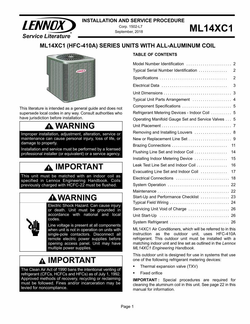
ML14XC1 (HFC-410A) SERIES UNITS WITH ALL-ALUMINUM COIL
This literature is intended as a general guide and does not
supersede local codes in any way. Consult authorities whohave jurisdiction before installation.
WARNINGImproper installation, adjustment, alteration, service ormaintenance can cause personal injury, loss of life, ordamage to property.
Installation and service must be performed by a licensedprofessional installer (or equivalent) or a service agency.
IMPORTANTThis unit must be matched with an indoor coil asspecified in Lennox Engineering Handbook. Coilspreviously charged with HCFC-22 must be flushed.
WARNINGElectric Shock Hazard. Can cause injuryor death. Unit must be grounded inaccordance with national and localcodes.
Line voltage is present at all componentswhen unit is not in operation on units withsingle‐pole contactors. Disconnect allremote electric power supplies beforeopening access panel. Unit may havemultiple power supplies.
IMPORTANTThe Clean Air Act of 1990 bans the intentional venting ofrefrigerant (CFCs, HCFCs and HFCs) as of July 1, 1992.Approved methods of recovery, recycling or reclaimingmust be followed. Fines and/or incarceration may belevied for noncompliance.
TABLE OF CONTENTS
Model Number Identification 2. . . . . . . . . . . . . . . . . . . . . .
Typical Serial Number Identification 2. . . . . . . . . . . . . .
Specifications 2. . . . . . . . . . . . . . . . . . . . . . . . . . . . . . . . .
Electrical Data 3. . . . . . . . . . . . . . . . . . . . . . . . . . . . . . . .
Unit Dimensions 3. . . . . . . . . . . . . . . . . . . . . . . . . . . . . . . . .
Typical Unit Parts Arrangement 4. . . . . . . . . . . . . . . . . . .
Component Specifications 5. . . . . . . . . . . . . . . . . . . . . . . .
Refrigerant Metering Devices - Indoor Coil 5. . . . . . . . . .
Operating Manifold Gauge Set and Service Valves 5. . .
Unit Placement 7. . . . . . . . . . . . . . . . . . . . . . . . . . . . . . . . . .
Removing and Installing Louvers 8. . . . . . . . . . . . . . . . . .
New or Replacement Line Set 9. . . . . . . . . . . . . . . . . . . . .
Brazing Connections 11. . . . . . . . . . . . . . . . . . . . . . . . . . .
Flushing Line Set and Indoor Coil 14. . . . . . . . . . . . . . . .
Installing Indoor Metering Device 15. . . . . . . . . . . . . . . .
Leak Test Line Set and Indoor Coil 16. . . . . . . . . . . . . . .
Evacuating Line Set and Indoor Coil 17. . . . . . . . . . . . .
Electrical Connections 18. . . . . . . . . . . . . . . . . . . . . . . . . .
System Operation 22. . . . . . . . . . . . . . . . . . . . . . . . . . . . . .
Maintenance 22. . . . . . . . . . . . . . . . . . . . . . . . . . . . . . . . . . .
Start-Up and Performance Checklist 23. . . . . . . . . . . . . .
Typical Field Wiring 24. . . . . . . . . . . . . . . . . . . . . . . . . . . . .
Servicing Unit Void of Charge 26. . . . . . . . . . . . . . . . . . . .
Unit Start-Up 26. . . . . . . . . . . . . . . . . . . . . . . . . . . . . . . . . .
System Refrigerant 26. . . . . . . . . . . . . . . . . . . . . . . . . . . . .
ML14XC1 Air Conditioners, which will be referred to in this
instruction as the outdoor unit, uses HFC-410Arefrigerant. This outdoor unit must be installed with amatching indoor unit and line set as outlined in the LennoxML14XC1 Engineering Handbook.
This outdoor unit is designed for use in systems that use
one of the following refrigerant metering devices:
� Thermal expansion valve (TXV)
� Fixed orifice
IMPORTANT�: Special procedures are required forcleaning the aluminum coil in this unit. See page 22 in thismanual for information.
Page 2
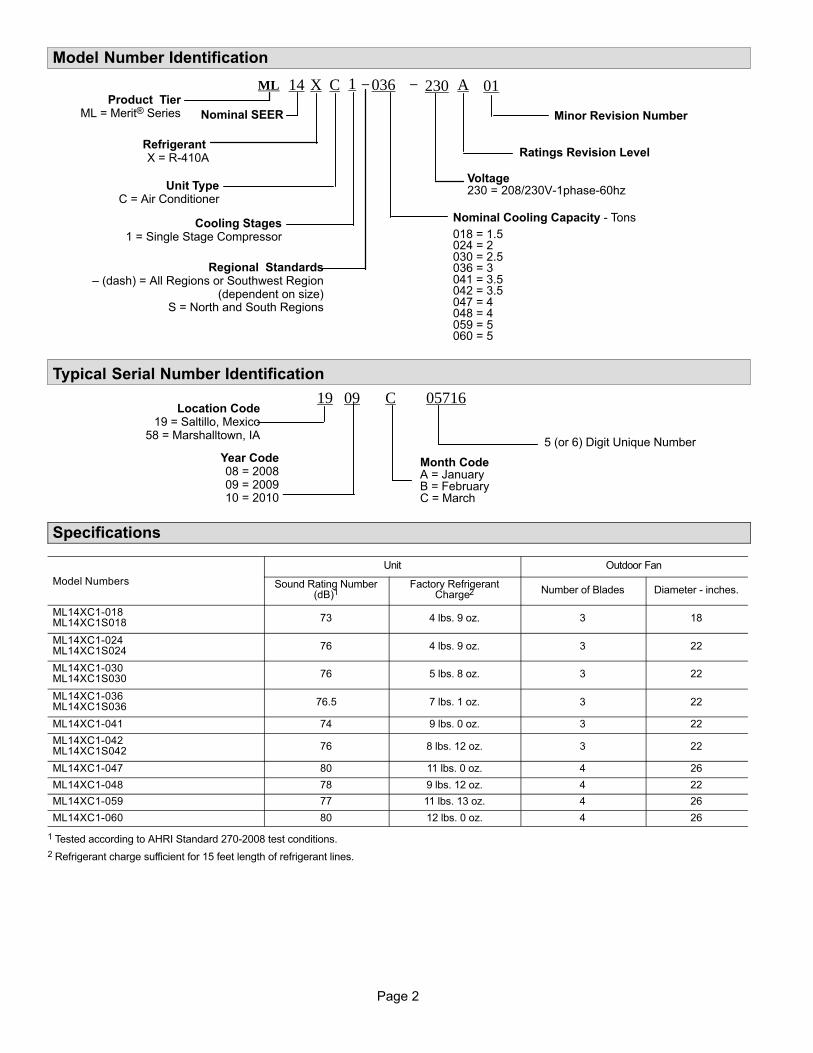
Model Number Identification
CX14 036 A
Unit TypeC = Air Conditioner
Refrigerant X = R-410A
Nominal Cooling Capacity - Tons
018 = 1.5024 = 2030 = 2.5036 = 3041 = 3.5042 = 3.5047 = 4048 = 4059 = 5060 = 5
Minor Revision NumberNominal SEER
01
Voltage230 = 208/230V-1phase-60hz
230−−MLProduct Tier
ML = Merit® Series
1
Cooling Stages1 = Single Stage Compressor
Regional Standards– (dash) = All Regions or Southwest Region
(dependent on size)S = North and South Regions
Ratings Revision Level
Typical Serial Number Identification
19 09 C
Year Code08 = 200809 = 200910 = 2010
Month CodeA = JanuaryB = February C = March
05716
5 (or 6) Digit Unique Number
Location Code19 = Saltillo, Mexico
58 = Marshalltown, IA
Specifications
Model Numbers
Unit Outdoor Fan
Sound Rating Number(dB)1
Factory RefrigerantCharge2 Number of Blades Diameter - inches.
ML14XC1-018ML14XC1S018 73 4 lbs. 9 oz. 3 18
ML14XC1-024ML14XC1S024 76 4 lbs. 9 oz. 3 22
ML14XC1-030ML14XC1S030 76 5 lbs. 8 oz. 3 22
ML14XC1-036ML14XC1S036 76.5 7 lbs. 1 oz. 3 22
ML14XC1-041 74 9 lbs. 0 oz. 3 22
ML14XC1-042ML14XC1S042 76 8 lbs. 12 oz. 3 22
ML14XC1-047 80 11 lbs. 0 oz. 4 26
ML14XC1-048 78 9 lbs. 12 oz. 4 22
ML14XC1-059 77 11 lbs. 13 oz. 4 26
ML14XC1-060 80 12 lbs. 0 oz. 4 26
1 Tested according to AHRI Standard 270-2008 test conditions.
2 Refrigerant charge sufficient for 15 feet length of refrigerant lines.
Page 3
ML14XC1 SERIES
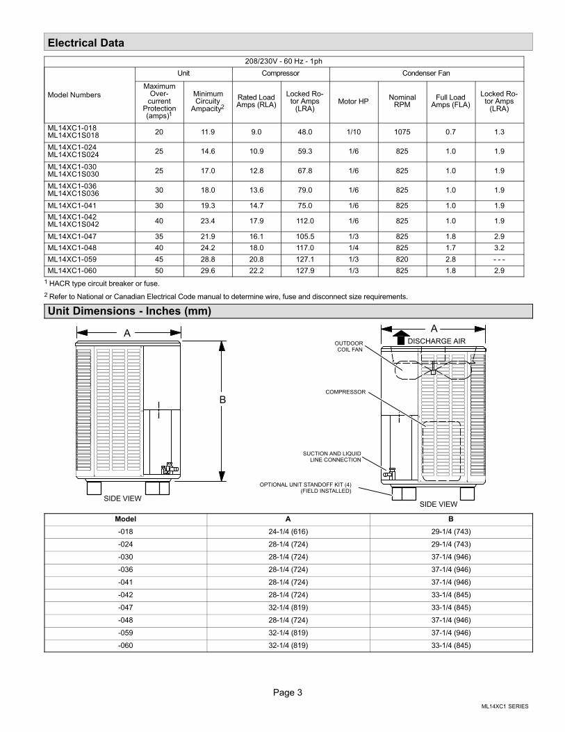
Electrical Data
208/230V - 60 Hz - 1ph
Model Numbers
Unit Compressor Condenser Fan
MaximumOver-
currentProtection(amps)1
MinimumCircuity
Ampacity2
Rated LoadAmps (RLA)
Locked Rotor Amps
(LRA)Motor HP
NominalRPM
Full LoadAmps (FLA)
Locked Rotor Amps
(LRA)
ML14XC1-018ML14XC1S018 20 11.9 9.0 48.0 1/10 1075 0.7 1.3
ML14XC1-024ML14XC1S024 25 14.6 10.9 59.3 1/6 825 1.0 1.9
ML14XC1-030ML14XC1S030 25 17.0 12.8 67.8 1/6 825 1.0 1.9
ML14XC1-036ML14XC1S036 30 18.0 13.6 79.0 1/6 825 1.0 1.9
ML14XC1-041 30 19.3 14.7 75.0 1/6 825 1.0 1.9
ML14XC1-042ML14XC1S042 40 23.4 17.9 112.0 1/6 825 1.0 1.9
ML14XC1-047 35 21.9 16.1 105.5 1/3 825 1.8 2.9
ML14XC1-048 40 24.2 18.0 117.0 1/4 825 1.7 3.2
ML14XC1-059 45 28.8 20.8 127.1 1/3 820 2.8 - - -
ML14XC1-060 50 29.6 22.2 127.9 1/3 825 1.8 2.9
1 HACR type circuit breaker or fuse.
2 Refer to National or Canadian Electrical Code manual to determine wire, fuse and disconnect size requirements.
Unit Dimensions - Inches (mm)
SUCTION AND LIQUIDLINE CONNECTION
DISCHARGE AIR
SIDE VIEW
OUTDOORCOIL FAN
COMPRESSOR
A
B
A
OPTIONAL UNIT STANDOFF KIT (4)(FIELD INSTALLED)
SIDE VIEW
Model A B
-018 24-1/4 (616) 29-1/4 (743)
-024 28-1/4 (724) 29-1/4 (743)
-030 28-1/4 (724) 37-1/4 (946)
-036 28-1/4 (724) 37-1/4 (946)
-041 28-1/4 (724) 37-1/4 (946)
-042 28-1/4 (724) 33-1/4 (845)
-047 32-1/4 (819) 33-1/4 (845)
-048 28-1/4 (724) 37-1/4 (946)
-059 32-1/4 (819) 37-1/4 (946)
-060 32-1/4 (819) 33-1/4 (845)
Page 4
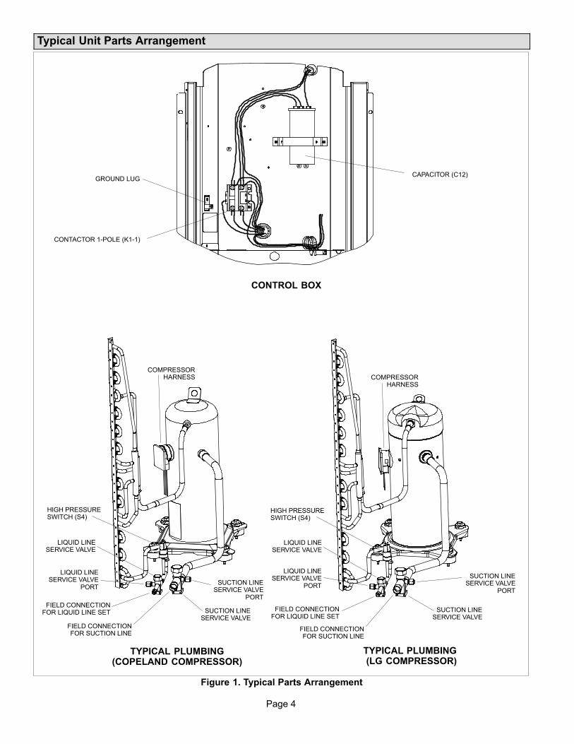
Typical Unit Parts Arrangement
FIELD CONNECTIONFOR LIQUID LINE SET
LIQUID LINESERVICE VALVE
LIQUID LINE SERVICE VALVE
PORTSUCTION LINE
SERVICE VALVE PORT
SUCTION LINESERVICE VALVE
FIELD CONNECTIONFOR SUCTION LINE
HIGH PRESSURESWITCH (S4)
COMPRESSORHARNESS
GROUND LUG
CONTACTOR 1-POLE (K1-1)
CAPACITOR (C12)
CONTROL BOX
TYPICAL PLUMBING(COPELAND COMPRESSOR)
TYPICAL PLUMBING (LG COMPRESSOR)
HIGH PRESSURESWITCH (S4)
FIELD CONNECTIONFOR LIQUID LINE SET
LIQUID LINESERVICE VALVE
LIQUID LINE SERVICE VALVE
PORT
FIELD CONNECTIONFOR SUCTION LINE
SUCTION LINESERVICE VALVE
SUCTION LINE SERVICE VALVE
PORT
COMPRESSORHARNESS
Figure 1. Typical Parts Arrangement
Page 5
ML14XC1 SERIES
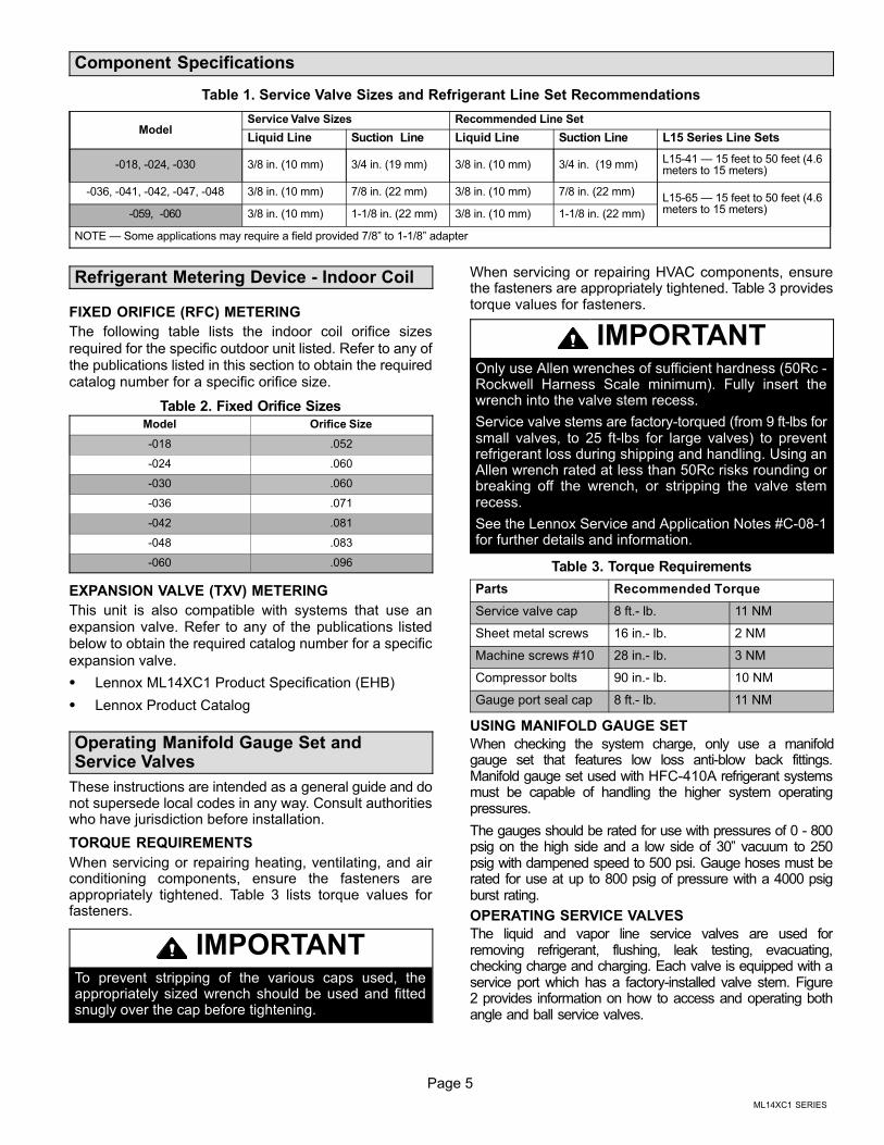
Component Specifications
Table 1. Service Valve Sizes and Refrigerant Line Set Recommendations
ModelService Valve Sizes Recommended Line Set
Liquid Line Suction Line Liquid Line Suction Line L15 Series Line Sets
-018, -024, -030 3/8 in. (10 mm) 3/4 in. (19 mm) 3/8 in. (10 mm) 3/4 in. (19 mm)L15-41 — 15 feet to 50 feet (4.6meters to 15 meters)
-036, -041, -042, -047, -048 3/8 in. (10 mm) 7/8 in. (22 mm) 3/8 in. (10 mm) 7/8 in. (22 mm)L15-65 — 15 feet to 50 feet (4.6meters to 15 meters)-059, -060 3/8 in. (10 mm) 1-1/8 in. (22 mm) 3/8 in. (10 mm) 1-1/8 in. (22 mm)
NOTE — Some applications may require a field provided 7/8” to 1-1/8” adapter
Refrigerant Metering Device - Indoor Coil
FIXED ORIFICE (RFC) METERING
The following table lists the indoor coil orifice sizes
required for the specific outdoor unit listed. Refer to any ofthe publications listed in this section to obtain the requiredcatalog number for a specific orifice size.
Table 2. Fixed Orifice Sizes
Model Orifice Size
-018 .052
-024 .060
-030 .060
-036 .071
-042 .081
-048 .083
-060 .096
EXPANSION VALVE (TXV) METERING
This unit is also compatible with systems that use anexpansion valve. Refer to any of the publications listedbelow to obtain the required catalog number for a specific
expansion valve.
� Lennox ML14XC1 Product Specification (EHB)
� Lennox Product Catalog
Operating Manifold Gauge Set andService Valves
These instructions are intended as a general guide and donot supersede local codes in any way. Consult authoritieswho have jurisdiction before installation.
TORQUE REQUIREMENTS
When servicing or repairing heating, ventilating, and airconditioning components, ensure the fasteners areappropriately tightened. Table 3 lists torque values forfasteners.
IMPORTANTTo prevent stripping of the various caps used, theappropriately sized wrench should be used and fittedsnugly over the cap before tightening.
When servicing or repairing HVAC components, ensurethe fasteners are appropriately tightened. Table 3 providestorque values for fasteners.
IMPORTANTOnly use Allen wrenches of sufficient hardness (50Rc -Rockwell Harness Scale minimum). Fully insert thewrench into the valve stem recess.
Service valve stems are factory-torqued (from 9 ft-lbs forsmall valves, to 25 ft-lbs for large valves) to preventrefrigerant loss during shipping and handling. Using anAllen wrench rated at less than 50Rc risks rounding orbreaking off the wrench, or stripping the valve stemrecess.
See the Lennox Service and Application Notes #C-08-1for further details and information.
Table 3. Torque Requirements
Parts Recommended Torque
Service valve cap 8 ft.- lb. 11 NM
Sheet metal screws 16 in.- lb. 2 NM
Machine screws #10 28 in.- lb. 3 NM
Compressor bolts 90 in.- lb. 10 NM
Gauge port seal cap 8 ft.- lb. 11 NM
USING MANIFOLD GAUGE SET
When checking the system charge, only use a manifoldgauge set that features low loss anti-blow back fittings.Manifold gauge set used with HFC-410A refrigerant systemsmust be capable of handling the higher system operatingpressures.
The gauges should be rated for use with pressures of 0 - 800psig on the high side and a low side of 30” vacuum to 250psig with dampened speed to 500 psi. Gauge hoses must berated for use at up to 800 psig of pressure with a 4000 psigburst rating.
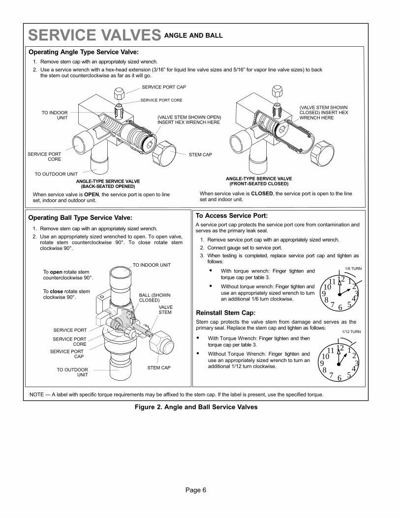
OPERATING SERVICE VALVES
The liquid and vapor line service valves are used forremoving refrigerant, flushing, leak testing, evacuating,checking charge and charging. Each valve is equipped with aservice port which has a factory-installed valve stem. Figure2 provides information on how to access and operating bothangle and ball service valves.
Page 6
(VALVE STEM SHOWNCLOSED) INSERT HEXWRENCH HERE
SERVICE PORT CORE
SERVICE PORT CAP
ANGLE-TYPE SERVICE VALVE(FRONT-SEATED CLOSED)
SERVICE PORTCORE
TO OUTDOOR UNIT
STEM CAP
(VALVE STEM SHOWN OPEN)INSERT HEX WRENCH HERE
TO INDOORUNIT
ANGLE-TYPE SERVICE VALVE(BACK-SEATED OPENED)
BALL (SHOWNCLOSED)
SERVICE PORTCORE
TO INDOOR UNIT
TO OUTDOORUNIT
To open rotate stemcounterclockwise 90°.
To close rotate stemclockwise 90°.
SERVICE PORT
SERVICE PORTCAP
STEM CAP
VALVESTEM
SERVICE VALVES ANGLE AND BALL
Operating Angle Type Service Valve:
1. Remove stem cap with an appropriately sized wrench.
2. Use a service wrench with a hex-head extension (3/16” for liquid line valve sizes and 5/16” for vapor line valve sizes) to backthe stem out counterclockwise as far as it will go.
Operating Ball Type Service Valve:
1. Remove stem cap with an appropriately sized wrench.
2. Use an appropriately sized wrenched to open. To open valve,rotate stem counterclockwise 90°. To close rotate stemclockwise 90°.
123
4567
8910
11 12
1/12 TURN
To Access Service Port:
A service port cap protects the service port core from contamination andserves as the primary leak seal.
1. Remove service port cap with an appropriately sized wrench.
2. Connect gauge set to service port.
3. When testing is completed, replace service port cap and tighten asfollows:
� With torque wrench: Finger tighten and
torque cap per table 3.
� Without torque wrench: Finger tighten and
use an appropriately sized wrench to turnan additional 1/6 turn clockwise.
123
4567
8910
11 12
1/6 TURN
When service valve is CLOSED, the service port is open to the lineset and indoor unit.
When service valve is OPEN, the service port is open to lineset, indoor and outdoor unit.
Reinstall Stem Cap:
Stem cap protects the valve stem from damage and serves as theprimary seal. Replace the stem cap and tighten as follows:
� With Torque Wrench: Finger tighten and then
torque cap per table 3.
� Without Torque Wrench: Finger tighten and
use an appropriately sized wrench to turn anadditional 1/12 turn clockwise.
NOTE — A label with specific torque requirements may be affixed to the stem cap. If the label is present, use the specified torque.
Figure 2. Angle and Ball Service Valves
Page 7
ML14XC1 SERIES
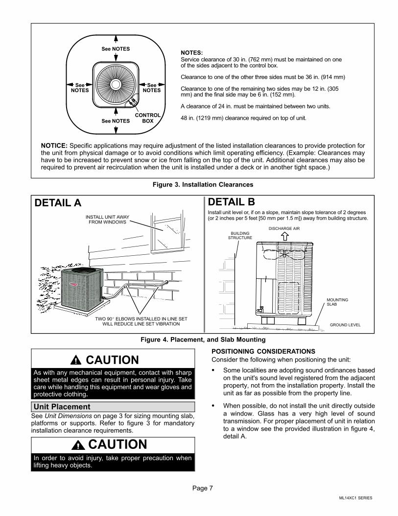
NOTES:Service clearance of 30 in. (762 mm) must be maintained on oneof the sides adjacent to the control box.
Clearance to one of the other three sides must be 36 in. (914 mm)
Clearance to one of the remaining two sides may be 12 in. (305mm) and the final side may be 6 in. (152 mm).
A clearance of 24 in. must be maintained between two units.
48 in. (1219 mm) clearance required on top of unit.
SeeNOTES
See NOTES
See NOTES
SeeNOTES
CONTROLBOX
NOTICE: Specific applications may require adjustment of the listed installation clearances to provide protection forthe unit from physical damage or to avoid conditions which limit operating efficiency. (Example: Clearances mayhave to be increased to prevent snow or ice from falling on the top of the unit. Additional clearances may also berequired to prevent air recirculation when the unit is installed under a deck or in another tight space.)
Figure 3. Installation Clearances
Install unit level or, if on a slope, maintain slope tolerance of 2 degrees(or 2 inches per 5 feet [50 mm per 1.5 m]) away from building structure.
DETAIL A DETAIL B
INSTALL UNIT AWAYFROM WINDOWS
TWO 90� ELBOWS INSTALLED IN LINE SETWILL REDUCE LINE SET VIBRATION GROUND LEVEL
MOUNTINGSLAB
BUILDINGSTRUCTURE
DISCHARGE AIR
Figure 4. Placement, and Slab Mounting
CAUTIONAs with any mechanical equipment, contact with sharpsheet metal edges can result in personal injury. Takecare while handling this equipment and wear gloves andprotective clothing.
Unit PlacementSee Unit Dimensions on page 3 for sizing mounting slab,platforms or supports. Refer to figure 3 for mandatoryinstallation clearance requirements.
CAUTIONIn order to avoid injury, take proper precaution whenlifting heavy objects.
POSITIONING CONSIDERATIONS
Consider the following when positioning the unit:
� Some localities are adopting sound ordinances based
on the unit's sound level registered from the adjacentproperty, not from the installation property. Install the
unit as far as possible from the property line.
� When possible, do not install the unit directly outside
a window. Glass has a very high level of soundtransmission. For proper placement of unit in relation
to a window see the provided illustration in figure 4,detail A.
Page 8
PLACING UNIT ON SLAB
When installing unit at grade level, the top of the slabshould be high enough above grade so that water fromhigher ground will not collect around the unit. The slabshould have a slope tolerance as described in figure 4,detail B.
ROOF MOUNTING
Install the unit a minimum of 6 inches (152 mm) above theroof surface to avoid ice build-up around the unit. Locatethe unit above a load bearing wall or area of the roof thatcan adequately support the unit. Consult local codes forrooftop applications.
If unit coil cannot be mounted away from prevailing winterwinds, a wind barrier should be constructed. Size barrier at
least the same height and width as outdoor unit. Mountbarrier 24 inches (610 mm) from the sides of the unit in thedirection of prevailing winds.
NOTICERoof Damage!
This system contains both refrigerant and oil. Somerubber roofing material may absorb oil and cause therubber to swell when it comes into contact with oil. Therubber will then bubble and could cause leaks. Protectthe roof surface to avoid exposure to refrigerant and oilduring service and installation. Failure to follow thisnotice could result in damage to roof surface.
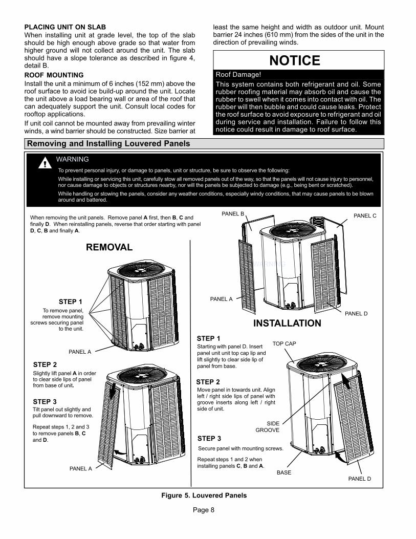
Removing and Installing Louvered Panels
WARNING
To prevent personal injury, or damage to panels, unit or structure, be sure to observe the following:
While installing or servicing this unit, carefully stow all removed panels out of the way, so that the panels will not cause injury to personnel,nor cause damage to objects or structures nearby, nor will the panels be subjected to damage (e.g., being bent or scratched).
While handling or stowing the panels, consider any weather conditions, especially windy conditions, that may cause panels to be blownaround and battered.
WARNING
PANEL A
PANEL B PANEL C
PANEL D
When removing the unit panels. Remove panel A first, then B, C and
finally D. When reinstalling panels, reverse that order starting with panel
D, C, B and finally A.
REMOVAL
Repeat steps 1, 2 and 3
to remove panels B, C
and D.
STEP 1
Starting with panel D. Insert
panel unit unit top cap lip and
lift slightly to clear side lip of
panel from base.
PANEL A
PANEL A
STEP 2
INSTALLATION
Repeat steps 1 and 2 when
installing panels C, B and A.
To remove panel,remove mounting
screws securing panelto the unit.
Slightly lift panel A in orderto clear side lips of panelfrom base of unit.
STEP 3Tilt panel out slightly andpull downward to remove.
STEP 1
STEP 2Move panel in towards unit. Alignleft / right side lips of panel withgroove inserts along left / rightside of unit.
PANEL D
TOP CAP
BASE
SIDE
GROOVE
STEP 3
Secure panel with mounting screws.
Figure 5. Louvered Panels
Page 9
ML14XC1 SERIES
New or Replacement Line Set
This section provides information on new installation orreplacement of existing line set. If a new or replacementline set is not required, then proceed to BrazingConnections on page 11.
Field refrigerant piping consists of liquid and suction linesfrom the outdoor unit (braze connections) to the indoor unitcoil (flare or braze connections). Use Lennox L15 (braze,non-flare) series line set, or use field-fabricated refrigerantlines as listed in table 1.
NOTE - When installing refrigerant lines longer than 50feet, see the Lennox Refrigerant Piping Design andFabrication Guidelines, CORP. 9351-L9, or contactLennox Technical Support Product Applications forassistance.
To obtain the correct information from Lennox, be sure tocommunicate the following points:
� Model (ML14XC1) and size of unit (e.g. -060).
� Line set diameters for the unit being installed as listed
in table 1 and total length of installation.
� Number of elbows and if there is a rise or drop of thepiping.
If refrigerant lines are routed through a wall, seal andisolate the opening so vibration is not transmitted to thebuilding. Pay close attention to line set isolation duringinstallation of any HVAC system. When properly isolatedfrom building structures (walls, ceilings. floors), therefrigerant lines will not create unnecessary vibration andsubsequent sounds.
IMPORTANTMineral oils are not compatible with HFC-410A. If oilmust be added, it must be a Polyol ester oil.
The compressor is charged with sufficient Polyol ester oilfor line set lengths up to 50 feet. Recommend adding oil tosystem based on the amount of refrigerant charge in thesystem. No need to add oil in a system with 20 pounds ofrefrigerant or less. For systems over 20 pounds - add oneounce for every five pounds of refrigerant over 20 pounds.
Recommended topping-off POE oils are Mobil EALARCTIC 22 CC or ICI EMKARATE� RL32CF.
MATCHING WITH NEW OR EXISTING INDOOR COILAND LINE SET
The RFC1-metering line consisted of a small bore copperline that ran from condenser to evaporator coil. Refrigerantwas metered into the evaporator by utilizingtemperature/pressure evaporation effects on refrigerant inthe small RFC line. The length and bore of the RFC linecorresponded to the size of cooling unit.
If the ML14XC1 is being used with either a new or existingindoor coil which is equipped with a liquid line which servedas a metering device (RFCI), the liquid line must bereplaced prior to the installation of the ML14XC1 unit.Typically a liquid line used to meter flow is 1/4” in diameterand copper.
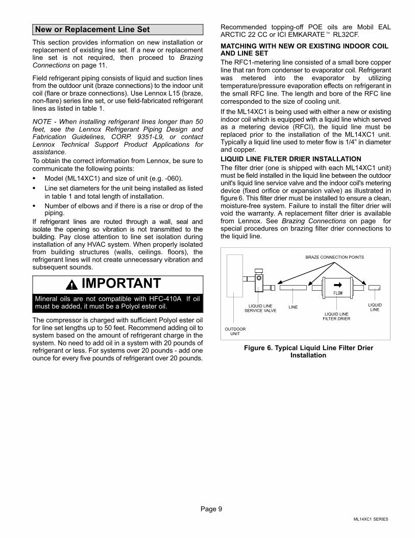
LIQUID LINE FILTER DRIER INSTALLATION
The filter drier (one is shipped with each ML14XC1 unit)must be field installed in the liquid line between the outdoorunit's liquid line service valve and the indoor coil's meteringdevice (fixed orifice or expansion valve) as illustrated infigure 6. This filter drier must be installed to ensure a clean,moisture-free system. Failure to install the filter drier willvoid the warranty. A replacement filter drier is availablefrom Lennox. See Brazing Connections on page forspecial procedures on brazing filter drier connections tothe liquid line.
OUTDOORUNIT
LIQUID LINESERVICE VALVE
LIQUID LINEFILTER DRIER
LINELIQUIDLINE
BRAZE CONNECTION POINTS
Figure 6. Typical Liquid Line Filter DrierInstallation
Page 10
ANCHORED HEAVY NYLONWIRE TIE OR AUTOMOTIVE
MUFFLER‐TYPE HANGER
STRAP LIQUID LINE TOVAPOR LINE
WALLSTUD
LIQUID LINE
NON-CORROSIVEMETAL SLEEVE
VAPOR LINE - WRAPPEDIN ARMAFLEX
AUTOMOTIVEMUFFLER‐TYPE HANGER
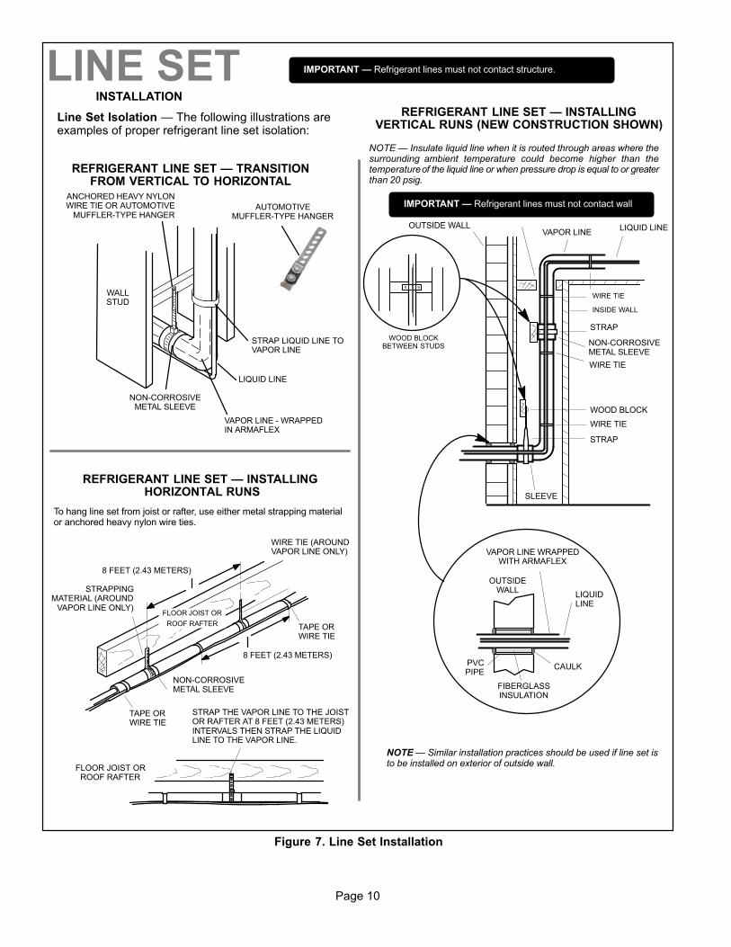
REFRIGERANT LINE SET — TRANSITIONFROM VERTICAL TO HORIZONTAL
Line Set Isolation — The following illustrations areexamples of proper refrigerant line set isolation:
STRAPPINGMATERIAL (AROUND
VAPOR LINE ONLY)
TAPE ORWIRE TIE
WIRE TIE (AROUNDVAPOR LINE ONLY)
FLOOR JOIST ORROOF RAFTER
TAPE ORWIRE TIE
To hang line set from joist or rafter, use either metal strapping materialor anchored heavy nylon wire ties.
8 FEET (2.43 METERS)
STRAP THE VAPOR LINE TO THE JOISTOR RAFTER AT 8 FEET (2.43 METERS)INTERVALS THEN STRAP THE LIQUIDLINE TO THE VAPOR LINE.
FLOOR JOIST OR
ROOF RAFTER
REFRIGERANT LINE SET — INSTALLING HORIZONTAL RUNS
NOTE — Similar installation practices should be used if line set isto be installed on exterior of outside wall.
PVCPIPE
FIBERGLASSINSULATION
CAULK
OUTSIDEWALL
VAPOR LINE WRAPPEDWITH ARMAFLEX
LIQUIDLINE
OUTSIDE WALL LIQUID LINEVAPOR LINE
WOOD BLOCKBETWEEN STUDS
STRAP
WOOD BLOCK
STRAP
SLEEVE
WIRE TIE
WIRE TIE
WIRE TIE
INSIDE WALL
REFRIGERANT LINE SET — INSTALLINGVERTICAL RUNS (NEW CONSTRUCTION SHOWN)
INSTALLATION
LINE SET
NOTE — Insulate liquid line when it is routed through areas where thesurrounding ambient temperature could become higher than thetemperature of the liquid line or when pressure drop is equal to or greaterthan 20 psig.
NON-CORROSIVEMETAL SLEEVE
IMPORTANT — Refrigerant lines must not contact structure.
NON-CORROSIVEMETAL SLEEVE
8 FEET (2.43 METERS)
IMPORTANT — Refrigerant lines must not contact wall
Figure 7. Line Set Installation
Page 11
ML14XC1 SERIES
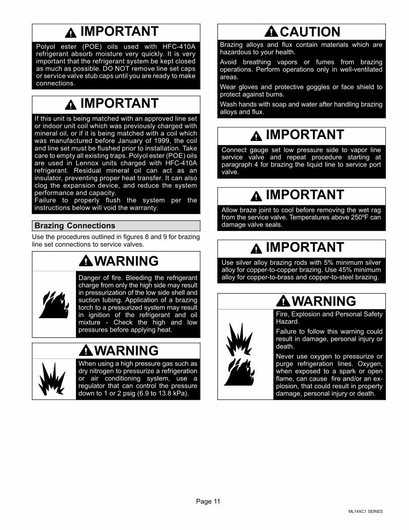
IMPORTANTPolyol ester (POE) oils used with HFC-410Arefrigerant absorb moisture very quickly. It is veryimportant that the refrigerant system be kept closedas much as possible. DO NOT remove line set capsor service valve stub caps until you are ready to makeconnections.
IMPORTANTIf this unit is being matched with an approved line setor indoor unit coil which was previously charged withmineral oil, or if it is being matched with a coil whichwas manufactured before January of 1999, the coiland line set must be flushed prior to installation. Takecare to empty all existing traps. Polyol ester (POE) oilsare used in Lennox units charged with HFC-410Arefrigerant. Residual mineral oil can act as aninsulator, preventing proper heat transfer. It can alsoclog the expansion device, and reduce the systemperformance and capacity.Failure to properly flush the system per theinstructions below will void the warranty.
Brazing Connections
Use the procedures outlined in figures 8 and 9 for brazingline set connections to service valves.
WARNINGDanger of fire. Bleeding the refrigerantcharge from only the high side may resultin pressurization of the low side shell andsuction tubing. Application of a brazingtorch to a pressurized system may resultin ignition of the refrigerant and oilmixture - Check the high and lowpressures before applying heat.
WARNINGWhen using a high pressure gas such asdry nitrogen to pressurize a refrigerationor air conditioning system, use aregulator that can control the pressuredown to 1 or 2 psig (6.9 to 13.8 kPa).
CAUTIONBrazing alloys and flux contain materials which arehazardous to your health.
Avoid breathing vapors or fumes from brazingoperations. Perform operations only in well-ventilatedareas.
Wear gloves and protective goggles or face shield toprotect against burns.
Wash hands with soap and water after handling brazingalloys and flux.
IMPORTANTConnect gauge set low pressure side to vapor lineservice valve and repeat procedure starting atparagraph 4 for brazing the liquid line to service portvalve.
IMPORTANTAllow braze joint to cool before removing the wet ragfrom the service valve. Temperatures above 250ºF candamage valve seals.
IMPORTANTUse silver alloy brazing rods with 5% minimum silveralloy for copper-to-copper brazing. Use 45% minimumalloy for copper-to-brass and copper-to-steel brazing.
WARNINGFire, Explosion and Personal SafetyHazard.
Failure to follow this warning couldresult in damage, personal injury ordeath.
Never use oxygen to pressurize orpurge refrigeration lines. Oxygen,when exposed to a spark or openflame, can cause fire and/or an explosion, that could result in propertydamage, personal injury or death.
Page 12
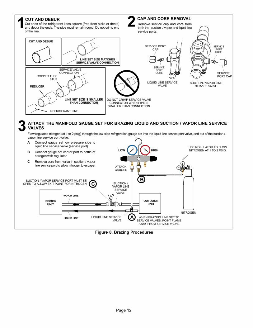
ATTACH THE MANIFOLD GAUGE SET FOR BRAZING LIQUID AND SUCTION / VAPOR LINE SERVICEVALVES
OUTDOORUNIT
LIQUID LINE
VAPOR LINE
LIQUID LINE SERVICEVALVE
SUCTION /VAPOR LINE
SERVICEVALVE
ATTACHGAUGES
INDOORUNIT
SUCTION / VAPOR SERVICE PORT MUST BEOPEN TO ALLOW EXIT POINT FOR NITROGEN
A Connect gauge set low pressure side toliquid line service valve (service port).
B Connect gauge set center port to bottle ofnitrogen with regulator.
C Remove core from valve in suction / vaporline service port to allow nitrogen to escape.
NITROGEN
HIGHLOWUSE REGULATOR TO FLOWNITROGEN AT 1 TO 2 PSIG.
B
A
C
WHEN BRAZING LINE SET TOSERVICE VALVES, POINT FLAME
AWAY FROM SERVICE VALVE.
Flow regulated nitrogen (at 1 to 2 psig) through the low-side refrigeration gauge set into the liquid line service port valve, and out of the suction /vapor line service port valve.
CUT AND DEBUR CAP AND CORE REMOVAL
Cut ends of the refrigerant lines square (free from nicks or dents)and debur the ends. The pipe must remain round. Do not crimp endof the line.
Remove service cap and core fromboth the suction / vapor and liquid lineservice ports.
1 2
LIQUID LINE SERVICEVALVE
SERVICEPORTCORE
SERVICE PORTCAP
SERVICEPORTCORE
SERVICEPORT CAP
CUT AND DEBUR
LINE SET SIZE MATCHESSERVICE VALVE CONNECTION
COPPER TUBESTUB
SERVICE VALVECONNECTION
REFRIGERANT LINE
DO NOT CRIMP SERVICE VALVECONNECTOR WHEN PIPE IS
SMALLER THAN CONNECTION
REDUCER
3
SUCTION / VAPOR LINESERVICE VALVE
LINE SET SIZE IS SMALLERTHAN CONNECTION
Figure 8. Brazing Procedures
Page 13
ML14XC1 SERIES
WHEN BRAZING LINE SET TOSERVICE VALVES, POINT FLAME
AWAY FROM SERVICE VALVE.
LIQUID LINE SERVICE VALVE
LIQUID LINE
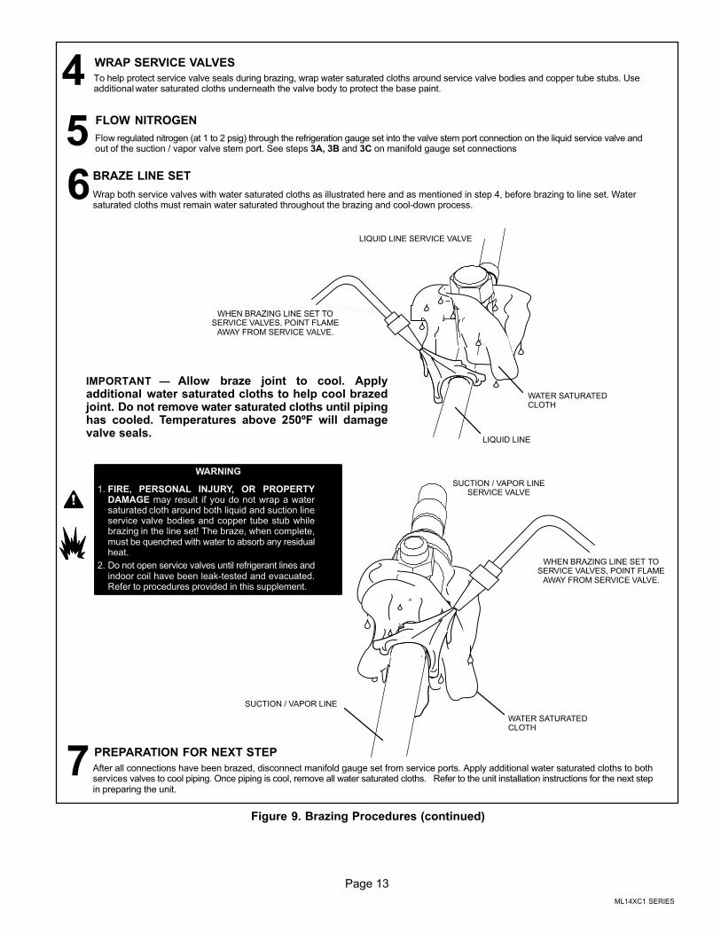
BRAZE LINE SET
Wrap both service valves with water saturated cloths as illustrated here and as mentioned in step 4, before brazing to line set. Watersaturated cloths must remain water saturated throughout the brazing and cool-down process.
WATER SATURATEDCLOTH
IMPORTANT — Allow braze joint to cool. Applyadditional water saturated cloths to help cool brazedjoint. Do not remove water saturated cloths until pipinghas cooled. Temperatures above 250ºF will damagevalve seals.
6
SUCTION / VAPOR LINE
WATER SATURATEDCLOTH
SUCTION / VAPOR LINESERVICE VALVE
After all connections have been brazed, disconnect manifold gauge set from service ports. Apply additional water saturated cloths to bothservices valves to cool piping. Once piping is cool, remove all water saturated cloths. Refer to the unit installation instructions for the next stepin preparing the unit.
WHEN BRAZING LINE SET TOSERVICE VALVES, POINT FLAME
AWAY FROM SERVICE VALVE.
PREPARATION FOR NEXT STEP7
WARNING
1. FIRE, PERSONAL INJURY, OR PROPERTYDAMAGE may result if you do not wrap a watersaturated cloth around both liquid and suction lineservice valve bodies and copper tube stub whilebrazing in the line set! The braze, when complete,must be quenched with water to absorb any residualheat.
2. Do not open service valves until refrigerant lines andindoor coil have been leak-tested and evacuated.Refer to procedures provided in this supplement.
WRAP SERVICE VALVES
To help protect service valve seals during brazing, wrap water saturated cloths around service valve bodies and copper tube stubs. Useadditional water saturated cloths underneath the valve body to protect the base paint.
4FLOW NITROGEN
Flow regulated nitrogen (at 1 to 2 psig) through the refrigeration gauge set into the valve stem port connection on the liquid service valve andout of the suction / vapor valve stem port. See steps 3A, 3B and 3C on manifold gauge set connections
5
Figure 9. Brazing Procedures (continued)
Page 14
Flushing Line Set and Indoor Coil
SENSINGLINE
TEFLON® RING
FIXED ORIFICE
BRASS NUT
LIQUID LINE ASSEMBLY(INCLUDES STRAINER)
LIQUID LINE ORIFICE HOUSING
DISTRIBUTOR TUBES
DISTRIBUTORASSEMBLY
REMOVE AND DISCARD
WHITE TEFLON® SEAL(IF PRESENT)
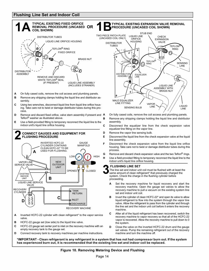
A On fully cased coils, remove the coil access and plumbing panels.
B Remove any shipping clamps holding the liquid line and distributor assembly.
C Using two wrenches, disconnect liquid line from liquid line orifice housing. Take care not to twist or damage distributor tubes during this process.
D Remove and discard fixed orifice, valve stem assembly if present andTeflon® washer as illustrated above.
E Use a field-provided fitting to temporary reconnect the liquid line to theindoor unit's liquid line orifice housing.
TYPICAL EXISTING FIXED ORIFICEREMOVAL PROCEDURE (UNCASEDCOIL SHOWN)
TYPICAL EXISTING EXPANSION VALVE REMOVALPROCEDURE (UNCASED COIL SHOWN)
TWO PIECE PATCH PLATE(UNCASED COIL ONLY)
VAPORLINE
DISTRIBUTORASSEMBLY
DISTRIBUTORTUBES
LIQUIDLINE
MALE EQUALIZERLINE FITTING
EQUALIZERLINE
CHECKEXPANSION
VALVE
TEFLON®
RING
STUB END
TEFLON®
RING
SENSING BULB
LIQUID LINEORIFICE
HOUSING
LIQUID LINEASSEMBLY WITH
BRASS NUT
A On fully cased coils, remove the coil access and plumbing panels.
B Remove any shipping clamps holding the liquid line and distributorassembly.
C Disconnect the equalizer line from the check expansion valveequalizer line fitting on the vapor line.
D Remove the vapor line sensing bulb.
E Disconnect the liquid line from the check expansion valve at the liquidline assembly.
F Disconnect the check expansion valve from the liquid line orificehousing. Take care not to twist or damage distributor tubes during thisprocess.
G Remove and discard check expansion valve and the two Teflon® rings.
H Use a field-provided fitting to temporary reconnect the liquid line to theindoor unit's liquid line orifice housing.
LOW HIGH
EXISTINGINDOOR
UNIT
GAUGEMANIFOLD
INVERTED HCFC-22CYLINDER CONTAINSCLEAN HCFC-22* TO BEUSED FOR FLUSHING.
LIQUID LINE SERVICEVALVE
INLET
DISCHARGE
TANKRETURN
CLOSEDOPENED
RECOVERYCYLINDER
RECOVERY MACHINE
NEWOUTDOOR
UNIT
VAPOR LINESERVICE VALVE
VA
PO
R
LIQ
UID
1
A Inverted HCFC-22 cylinder with clean refrigerant* to the vapor servicevalve.
B HCFC-22 gauge set (low side) to the liquid line valve.
C HCFC-22 gauge set center port to inlet on the recovery machine with anempty recovery tank to the gauge set.
D Connect recovery tank to recovery machines per machine instructions.
CONNECT GAUGES AND EQUIPMENT FORFLUSHING PROCEDURE
A
B
CD
B
OR
FLUSHING LINE SET
A Set the recovery machine for liquid recovery and start therecovery machine. Open the gauge set valves to allow therecovery machine to pull a vacuum on the existing system lineset and indoor unit coil.
B Invert the cylinder of clean HCFC-22* and open its valve to allowliquid refrigerant to flow into the system through the vapor linevalve. Allow the refrigerant to pass from the cylinder and throughthe line set and the indoor unit coil before it enters the recoverymachine.
C After all of the liquid refrigerant has been recovered, switch therecovery machine to vapor recovery so that all of the HCFC-22vapor is recovered. Allow the recovery machine to pull down to 0the system.
D Close the valve on the inverted HCFC-22 drum and the gaugeset valves. Pump the remaining refrigerant out of the recoverymachine and turn the machine off.
The line set and indoor unit coil must be flushed with at least thesame amount of clean refrigerant* that previously charged thesystem. Check the charge in the flushing cylinder beforeproceeding.
1A
2
3
1B
*IMPORTANT - Clean refrigerant is any refrigerant in a system that has not had compressor burn out. If the systemhas experienced burn out, it is recommended that the existing line set and indoor coil be replaced.
Figure 10. Removing Metering Device and Flushing
Page 15
ML14XC1 SERIES
Installing Indoor Metering Device
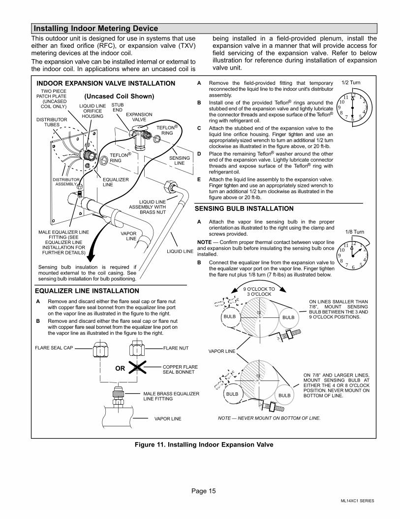
This outdoor unit is designed for use in systems that useeither an fixed orifice (RFC), or expansion valve (TXV)metering devices at the indoor coil.
The expansion valve can be installed internal or external tothe indoor coil. In applications where an uncased coil is
being installed in a field-provided plenum, install theexpansion valve in a manner that will provide access forfield servicing of the expansion valve. Refer to belowillustration for reference during installation of expansionvalve unit.
A Attach the vapor line sensing bulb in the properorientation as illustrated to the right using the clamp andscrews provided.
NOTE — Confirm proper thermal contact between vapor lineand expansion bulb before insulating the sensing bulb onceinstalled.
B Connect the equalizer line from the expansion valve tothe equalizer vapor port on the vapor line. Finger tightenthe flare nut plus 1/8 turn (7 ft-lbs) as illustrated below.
TWO PIECEPATCH PLATE
(UNCASEDCOIL ONLY)
VAPORLINE
LIQUID LINEORIFICE
HOUSINGDISTRIBUTOR
TUBES
LIQUID LINE
MALE EQUALIZER LINEFITTING (SEE
EQUALIZER LINEINSTALLATION FORFURTHER DETAILS)
SENSINGLINE
EQUALIZERLINE
EXPANSIONVALVE
TEFLON®
RING
(Uncased Coil Shown)
Sensing bulb insulation is required ifmounted external to the coil casing. Seesensing bulb installation for bulb positioning.
STUBEND
TEFLON®
RING
LIQUID LINEASSEMBLY WITH
BRASS NUT
DISTRIBUTORASSEMBLY
A Remove the field-provided fitting that temporaryreconnected the liquid line to the indoor unit's distributorassembly.
B Install one of the provided Teflon® rings around thestubbed end of the expansion valve and lightly lubricatethe connector threads and expose surface of the Teflon®
ring with refrigerant oil.
C Attach the stubbed end of the expansion valve to theliquid line orifice housing. Finger tighten and use anappropriately sized wrench to turn an additional 1/2 turnclockwise as illustrated in the figure above, or 20 ft-lb.
D Place the remaining Teflon® washer around the otherend of the expansion valve. Lightly lubricate connectorthreads and expose surface of the Teflon® ring withrefrigerant oil.
E Attach the liquid line assembly to the expansion valve.Finger tighten and use an appropriately sized wrench toturn an additional 1/2 turn clockwise as illustrated in thefigure above or 20 ft-lb.
ON 7/8” AND LARGER LINES,MOUNT SENSING BULB ATEITHER THE 4 OR 8 O'CLOCKPOSITION. NEVER MOUNT ONBOTTOM OF LINE.
12
ON LINES SMALLER THAN7/8”, MOUNT SENSINGBULB BETWEEN THE 3 AND9 O'CLOCK POSITIONS.
12
BULB
VAPOR LINE
NOTE — NEVER MOUNT ON BOTTOM OF LINE.
BULB
BULBBULB
VAPOR LINE
FLARE NUT
COPPER FLARESEAL BONNET
MALE BRASS EQUALIZERLINE FITTING
FLARE SEAL CAP
OR
123
4567
8910
11 12
1/2 Turn
SENSING BULB INSTALLATION
EQUALIZER LINE INSTALLATION
123
4567
8910
11 12
1/8 Turn
A Remove and discard either the flare seal cap or flare nutwith copper flare seal bonnet from the equalizer line porton the vapor line as illustrated in the figure to the right.
B Remove and discard either the flare seal cap or flare nutwith copper flare seal bonnet from the equalizer line port onthe vapor line as illustrated in the figure to the right.
INDOOR EXPANSION VALVE INSTALLATION
9 O'CLOCK TO3 O'CLOCK
Figure 11. Installing Indoor Expansion Valve
Page 16
IMPORTANTThe Environmental Protection Agency (EPA) prohibitsthe intentional venting of HFC refrigerants duringmaintenance, service, repair and disposal of appliance.Approved methods of recovery, recycling or reclaimingmust be followed.
IMPORTANTIf this unit is being matched with an approved line setor indoor unit coil which was previously charged withmineral oil, or if it is being matched with a coil whichwas manufactured before January of 1999, the coiland line set must be flushed prior to installation. Takecare to empty all existing traps. Polyol ester (POE) oilsare used in Lennox units charged with HFC-410Arefrigerant. Residual mineral oil can act as aninsulator, preventing proper heat transfer. It can alsoclog the expansion device, and reduce the systemperformance and capacity.Failure to properly flush the system per theinstructions below will void the warranty.
Leak Test Line Set and Indoor Coil
WARNINGWhen using a high pressure gas such asdry nitrogen to pressurize a refrigerationor air conditioning system, use aregulator that can control the pressuredown to 1 or 2 psig (6.9 to 13.8 kPa).
IMPORTANTLeak detector must be capable of sensing HFCrefrigerant.
WARNINGRefrigerant can be harmful if it is inhaled. Refrigerantmust be used and recovered responsibly.
Failure to follow this warning may result in personal injuryor death.
TO VAPORSERVICE VALVE
HFC-410A
MANIFOLD GAUGE SET
OUTDOOR UNIT
HIGHLOW
NITROGEN
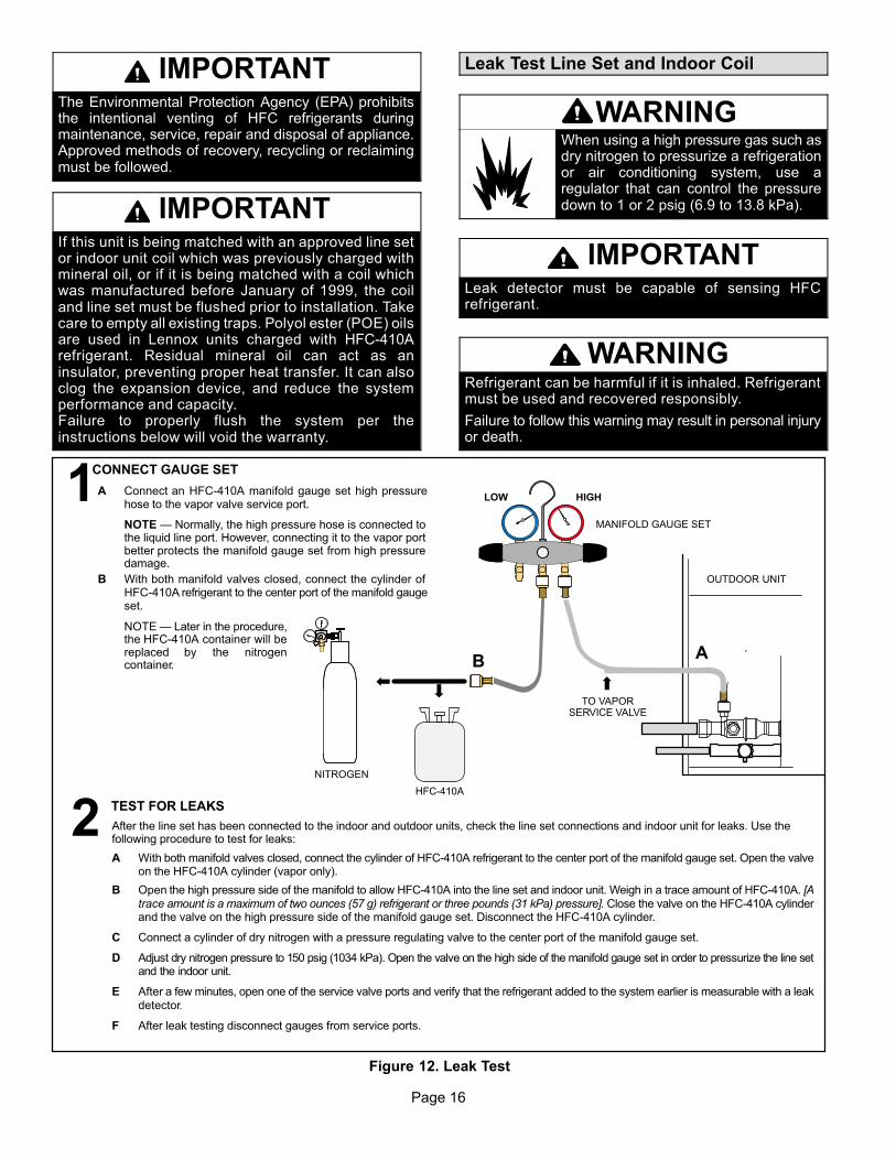
A With both manifold valves closed, connect the cylinder of HFC-410A refrigerant to the center port of the manifold gauge set. Open the valveon the HFC-410A cylinder (vapor only).
B Open the high pressure side of the manifold to allow HFC-410A into the line set and indoor unit. Weigh in a trace amount of HFC-410A. [Atrace amount is a maximum of two ounces (57 g) refrigerant or three pounds (31 kPa) pressure]. Close the valve on the HFC-410A cylinderand the valve on the high pressure side of the manifold gauge set. Disconnect the HFC-410A cylinder.
C Connect a cylinder of dry nitrogen with a pressure regulating valve to the center port of the manifold gauge set.
D Adjust dry nitrogen pressure to 150 psig (1034 kPa). Open the valve on the high side of the manifold gauge set in order to pressurize the line setand the indoor unit.
E After a few minutes, open one of the service valve ports and verify that the refrigerant added to the system earlier is measurable with a leakdetector.
F After leak testing disconnect gauges from service ports.
After the line set has been connected to the indoor and outdoor units, check the line set connections and indoor unit for leaks. Use thefollowing procedure to test for leaks:
A Connect an HFC-410A manifold gauge set high pressurehose to the vapor valve service port.
NOTE — Normally, the high pressure hose is connected tothe liquid line port. However, connecting it to the vapor portbetter protects the manifold gauge set from high pressuredamage.
B With both manifold valves closed, connect the cylinder ofHFC-410A refrigerant to the center port of the manifold gaugeset.
NOTE — Later in the procedure,the HFC-410A container will bereplaced by the nitrogencontainer.
1CONNECT GAUGE SET
2TEST FOR LEAKS
AB
Figure 12. Leak Test
Page 17
ML14XC1 SERIES
Evacuating Line Set and Indoor Coil
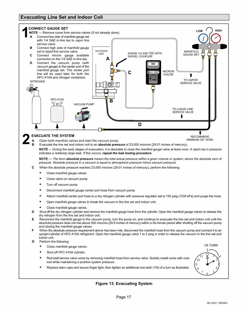
A Open both manifold valves and start the vacuum pump.
B Evacuate the line set and indoor unit to an absolute pressure of 23,000 microns (29.01 inches of mercury).
NOTE — During the early stages of evacuation, it is desirable to close the manifold gauge valve at least once. A rapid rise in pressure
indicates a relatively large leak. If this occurs, repeat the leak testing procedure.
NOTE — The term absolute pressure means the total actual pressure within a given volume or system, above the absolute zero ofpressure. Absolute pressure in a vacuum is equal to atmospheric pressure minus vacuum pressure.
C When the absolute pressure reaches 23,000 microns (29.01 inches of mercury), perform the following:
� Close manifold gauge valves
� Close valve on vacuum pump
� Turn off vacuum pump
� Disconnect manifold gauge center port hose from vacuum pump
� Attach manifold center port hose to a dry nitrogen cylinder with pressure regulator set to 150 psig (1034 kPa) and purge the hose.
� Open manifold gauge valves to break the vacuum in the line set and indoor unit.
� Close manifold gauge valves.
D Shut off the dry nitrogen cylinder and remove the manifold gauge hose from the cylinder. Open the manifold gauge valves to release thedry nitrogen from the line set and indoor unit.
E Reconnect the manifold gauge to the vacuum pump, turn the pump on, and continue to evacuate the line set and indoor unit until theabsolute pressure does not rise above 500 microns (29.9 inches of mercury) within a 20-minute period after shutting off the vacuum pumpand closing the manifold gauge valves.
F When the absolute pressure requirement above has been met, disconnect the manifold hose from the vacuum pump and connect it to anupright cylinder of HFC-410A refrigerant. Open the manifold gauge valve 1 to 2 psig in order to release the vacuum in the line set andindoor unit.
G Perform the following:
OUTDOOR
UNIT
TO VAPORSERVICE VALVE
TO LIQUID LINESERVICE VALVE
MICRONGAUGE
VACUUM PUMP
A34000 1/4 SAE TEE WITHSWIVEL COUPLER
500
MANIFOLDGAUGE SET
HFC-410A
RECOMMENDMINIMUM 3/8” HOSE
A Connect low side of manifold gauge setwith 1/4 SAE in-line tee to vapor lineservice valve
B Connect high side of manifold gaugeset to liquid line service valve
C Connect micron gauge availableconnector on the 1/4 SAE in-line tee.
D Connect the vacuum pump (withvacuum gauge) to the center port of themanifold gauge set. The center portline will be used later for both theHFC-410A and nitrogen containers.
HIGHLOW
12
34
56
78
910
11 12
1/6 TURN
NITROGEN
1CONNECT GAUGE SET
A
B
C
D
2EVACUATE THE SYSTEM
NOTE — Remove cores from service valves (if not already done).
� Close manifold gauge valves.
� Shut off HFC-410A cylinder.
� Reinstall service valve cores by removing manifold hose from service valve. Quickly install cores with core
tool while maintaining a positive system pressure.
� Replace stem caps and secure finger tight, then tighten an additional one-sixth (1/6) of a turn as illustrated.
Figure 13. Evacuating System
Page 18
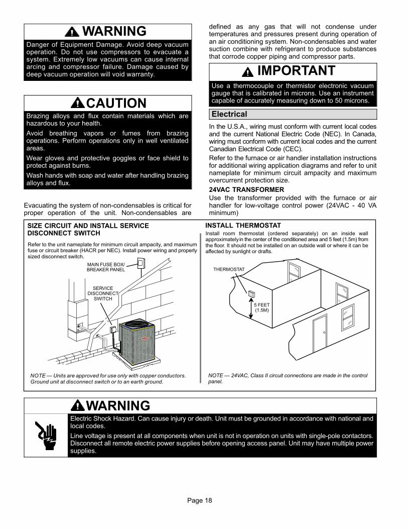
WARNINGDanger of Equipment Damage. Avoid deep vacuumoperation. Do not use compressors to evacuate asystem. Extremely low vacuums can cause internalarcing and compressor failure. Damage caused bydeep vacuum operation will void warranty.
CAUTIONBrazing alloys and flux contain materials which arehazardous to your health.
Avoid breathing vapors or fumes from brazingoperations. Perform operations only in well ventilatedareas.
Wear gloves and protective goggles or face shield toprotect against burns.
Wash hands with soap and water after handling brazingalloys and flux.
Evacuating the system of non-condensables is critical forproper operation of the unit. Non-condensables are
defined as any gas that will not condense undertemperatures and pressures present during operation ofan air conditioning system. Non-condensables and watersuction combine with refrigerant to produce substancesthat corrode copper piping and compressor parts.
IMPORTANTUse a thermocouple or thermistor electronic vacuumgauge that is calibrated in microns. Use an instrumentcapable of accurately measuring down to 50 microns.
Electrical
In the U.S.A., wiring must conform with current local codesand the current National Electric Code (NEC). In Canada,wiring must conform with current local codes and the currentCanadian Electrical Code (CEC).
Refer to the furnace or air handler installation instructionsfor additional wiring application diagrams and refer to unitnameplate for minimum circuit ampacity and maximumovercurrent protection size.
24VAC TRANSFORMER
Use the transformer provided with the furnace or airhandler for low‐voltage control power (24VAC - 40 VAminimum)
Refer to the unit nameplate for minimum circuit ampacity, and maximumfuse or circuit breaker (HACR per NEC). Install power wiring and properlysized disconnect switch.
NOTE — Units are approved for use only with copper conductors.Ground unit at disconnect switch or to an earth ground.
SIZE CIRCUIT AND INSTALL SERVICEDISCONNECT SWITCH
NOTE — 24VAC, Class II circuit connections are made in the controlpanel.
Install room thermostat (ordered separately) on an inside wallapproximately in the center of the conditioned area and 5 feet (1.5m) fromthe floor. It should not be installed on an outside wall or where it can beaffected by sunlight or drafts.
THERMOSTAT
5 FEET(1.5M)
INSTALL THERMOSTAT
SERVICEDISCONNECT
SWITCH
MAIN FUSE BOX/BREAKER PANEL
WARNINGElectric Shock Hazard. Can cause injury or death. Unit must be grounded in accordance with national andlocal codes.
Line voltage is present at all components when unit is not in operation on units with single‐pole contactors.Disconnect all remote electric power supplies before opening access panel. Unit may have multiple powersupplies.
Page 19
ML14XC1 SERIES
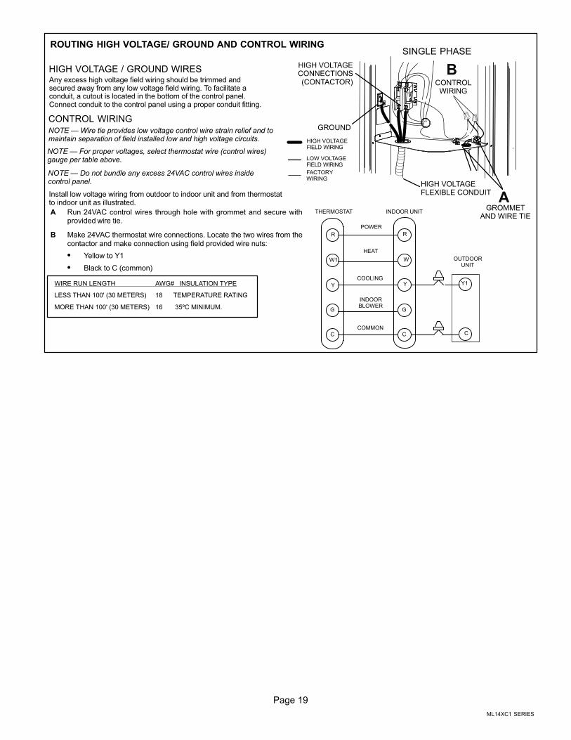
Any excess high voltage field wiring should be trimmed andsecured away from any low voltage field wiring. To facilitate aconduit, a cutout is located in the bottom of the control panel.Connect conduit to the control panel using a proper conduit fitting.
ROUTING HIGH VOLTAGE/ GROUND AND CONTROL WIRING
HIGH VOLTAGEFIELD WIRING
LOW VOLTAGEFIELD WIRING
FACTORYWIRING
WIRE RUN LENGTH AWG# INSULATION TYPE
LESS THAN 100' (30 METERS) 18 TEMPERATURE RATING
MORE THAN 100' (30 METERS) 16 35ºC MINIMUM.
Install low voltage wiring from outdoor to indoor unit and from thermostatto indoor unit as illustrated.
HIGH VOLTAGE / GROUND WIRES
CONTROL WIRING
A Run 24VAC control wires through hole with grommet and secure withprovided wire tie.
B Make 24VAC thermostat wire connections. Locate the two wires from thecontactor and make connection using field provided wire nuts:
� Yellow to Y1
� Black to C (common)
NOTE — For proper voltages, select thermostat wire (control wires)gauge per table above.
NOTE — Wire tie provides low voltage control wire strain relief and tomaintain separation of field installed low and high voltage circuits.
W1
Y
G
C
R
Y
G
C
THERMOSTAT INDOOR UNIT
POWER
HEAT
COOLING
INDOORBLOWER
COMMON
OUTDOORUNIT
Y1
C
W
R
SINGLE PHASE
NOTE — Do not bundle any excess 24VAC control wires insidecontrol panel.
CONTROLWIRING
HIGH VOLTAGECONNECTIONS(CONTACTOR)
GROUND
GROMMETAND WIRE TIE
HIGH VOLTAGEFLEXIBLE CONDUIT
A
B
Page 20
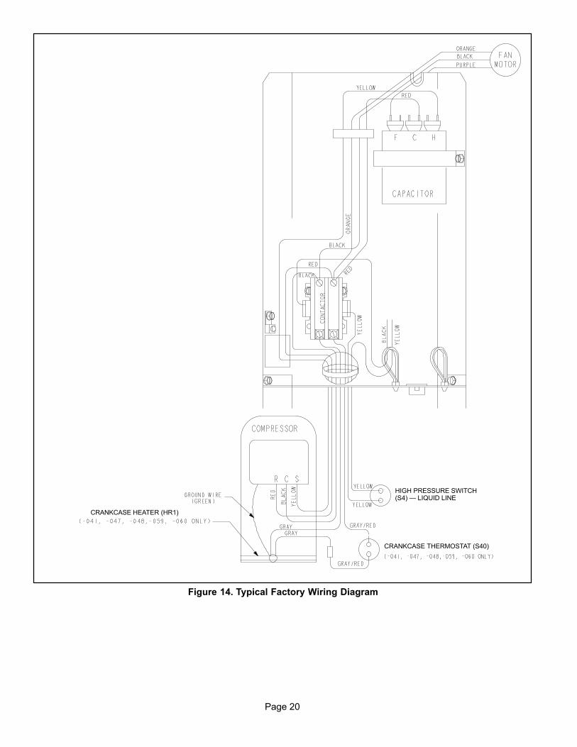
HIGH PRESSURE SWITCH(S4) — LIQUID LINE
CRANKCASE THERMOSTAT (S40)
CRANKCASE HEATER (HR1)
Figure 14. Typical Factory Wiring Diagram
Page 21
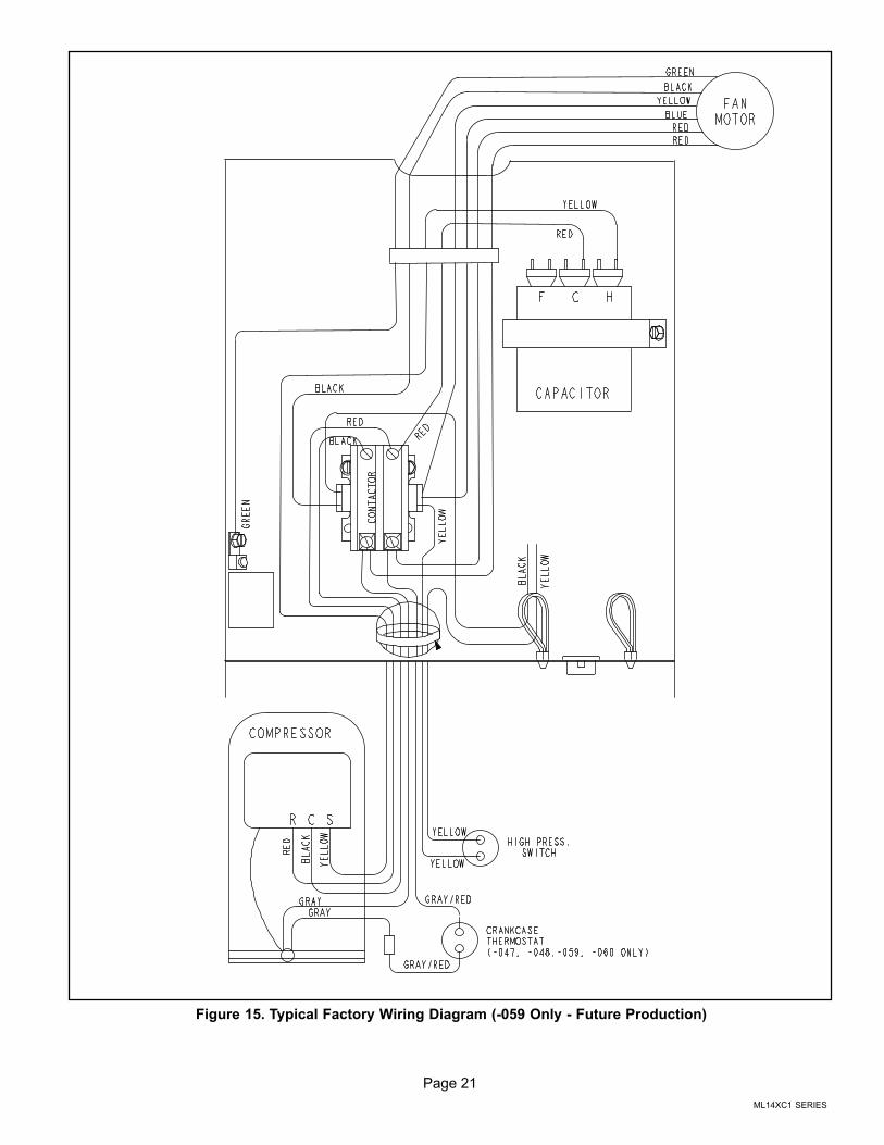
ML14XC1 SERIES
Figure 15. Typical Factory Wiring Diagram (-059 Only - Future Production)
Page 22
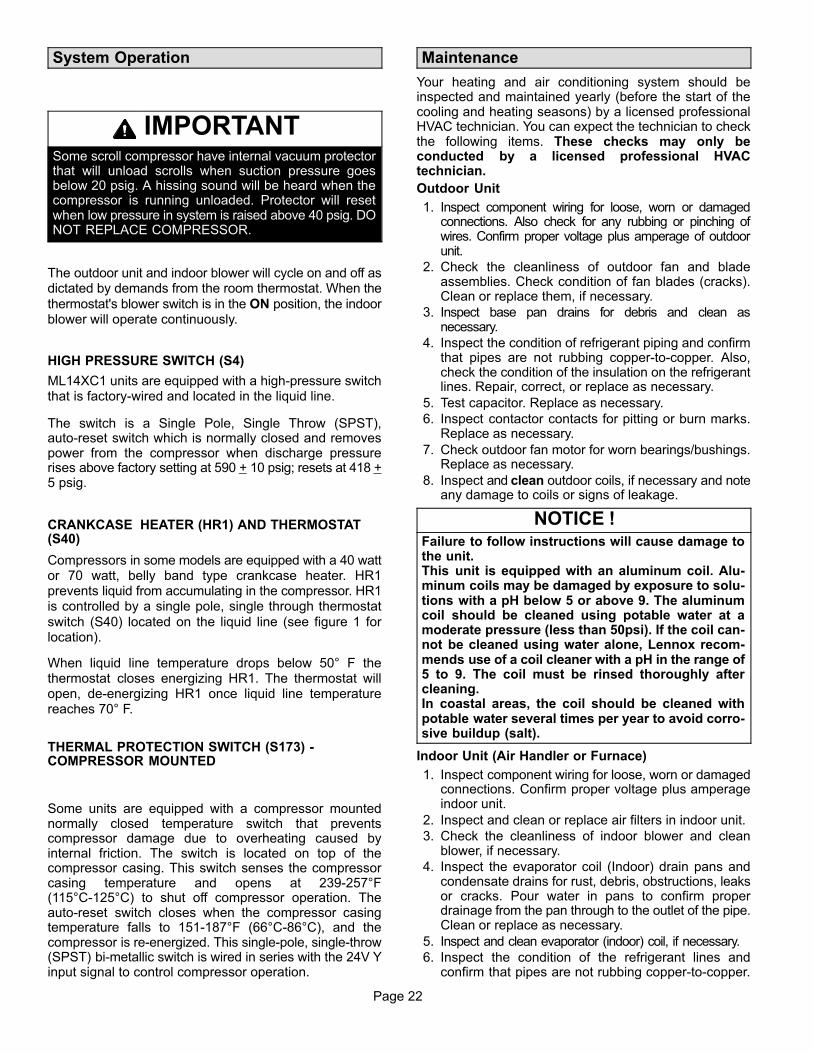
System Operation
IMPORTANTSome scroll compressor have internal vacuum protectorthat will unload scrolls when suction pressure goesbelow 20 psig. A hissing sound will be heard when thecompressor is running unloaded. Protector will resetwhen low pressure in system is raised above 40 psig. DONOT REPLACE COMPRESSOR.
The outdoor unit and indoor blower will cycle on and off asdictated by demands from the room thermostat. When the
thermostat's blower switch is in the ON position, the indoorblower will operate continuously.
HIGH PRESSURE SWITCH (S4)
ML14XC1 units are equipped with a high‐pressure switchthat is factory-wired and located in the liquid line.
The switch is a Single Pole, Single Throw (SPST),auto-reset switch which is normally closed and removespower from the compressor when discharge pressurerises above factory setting at 590 + 10 psig; resets at 418 +5 psig.
CRANKCASE HEATER (HR1) AND THERMOSTAT(S40)
Compressors in some models are equipped with a 40 wattor 70 watt, belly band type crankcase heater. HR1prevents liquid from accumulating in the compressor. HR1is controlled by a single pole, single through thermostat
switch (S40) located on the liquid line (see figure 1 forlocation).
When liquid line temperature drops below 50° F thethermostat closes energizing HR1. The thermostat willopen, de-energizing HR1 once liquid line temperaturereaches 70° F.
THERMAL PROTECTION SWITCH (S173) -COMPRESSOR MOUNTED
Some units are equipped with a compressor mountednormally closed temperature switch that preventscompressor damage due to overheating caused byinternal friction. The switch is located on top of thecompressor casing. This switch senses the compressorcasing temperature and opens at 239-257°F(115°C-125°C) to shut off compressor operation. Theauto-reset switch closes when the compressor casingtemperature falls to 151-187°F (66°C-86°C), and thecompressor is re-energized. This single-pole, single-throw(SPST) bi-metallic switch is wired in series with the 24V Yinput signal to control compressor operation.
Maintenance
Your heating and air conditioning system should beinspected and maintained yearly (before the start of thecooling and heating seasons) by a licensed professionalHVAC technician. You can expect the technician to checkthe following items. These checks may only beconducted by a licensed professional HVACtechnician.
Outdoor Unit
1. Inspect component wiring for loose, worn or damagedconnections. Also check for any rubbing or pinching ofwires. Confirm proper voltage plus amperage of outdoorunit.
2. Check the cleanliness of outdoor fan and bladeassemblies. Check condition of fan blades (cracks).Clean or replace them, if necessary.
3. Inspect base pan drains for debris and clean asnecessary.
4. Inspect the condition of refrigerant piping and confirmthat pipes are not rubbing copper-to-copper. Also,check the condition of the insulation on the refrigerantlines. Repair, correct, or replace as necessary.
5. Test capacitor. Replace as necessary.
6. Inspect contactor contacts for pitting or burn marks.Replace as necessary.
7. Check outdoor fan motor for worn bearings/bushings.Replace as necessary.
8. Inspect and clean outdoor coils, if necessary and noteany damage to coils or signs of leakage.
NOTICE !Failure to follow instructions will cause damage tothe unit. This unit is equipped with an aluminum coil. Aluminum coils may be damaged by exposure to solutions with a pH below 5 or above 9. The aluminumcoil should be cleaned using potable water at amoderate pressure (less than 50psi). If the coil cannot be cleaned using water alone, Lennox recommends use of a coil cleaner with a pH in the range of5 to 9. The coil must be rinsed thoroughly aftercleaning. In coastal areas, the coil should be cleaned withpotable water several times per year to avoid corrosive buildup (salt).
Indoor Unit (Air Handler or Furnace)
1. Inspect component wiring for loose, worn or damagedconnections. Confirm proper voltage plus amperageindoor unit.
2. Inspect and clean or replace air filters in indoor unit.
3. Check the cleanliness of indoor blower and cleanblower, if necessary.
4. Inspect the evaporator coil (Indoor) drain pans andcondensate drains for rust, debris, obstructions, leaksor cracks. Pour water in pans to confirm properdrainage from the pan through to the outlet of the pipe.Clean or replace as necessary.
5. Inspect and clean evaporator (indoor) coil, if necessary.
6. Inspect the condition of the refrigerant lines andconfirm that pipes are not rubbing copper-to-copper.
Page 23
ML14XC1 SERIES
Also, ensure that refrigerant pipes are not beingaffected by indoor air contamination. Check conditionof insulation on the refrigerant lines. Repair, correct, orreplace as necessary.
7. Inspect the duct system for leaks or other problems.Repair or replace as necessary.
8. Check for bearing/bushing wear on indoor blowermotor. Replace as necessary.
9. Indoor unit inspections of gas- or oil-fired furnaces willalso include inspection and cleaning of the burners,and a full inspection of the gas valve, heat exchangerand flue (exhaust) system.
General System Test with System Operating
1. Your technician should perform a general system test.He will turn on the air conditioner to check operatingfunctions such as the startup and shutoff operation.He will also check for unusual noises or odors, andmeasure indoor/outdoor temperatures and systempressures as needed.
2. The technician will check the refrigerant charge perthe charging sticker information on the outdoor unit.
3. Verify that system total static pressure and airflowsettings are within specific operating parameters.
4. Verify correct temperature drop across indoor coil.
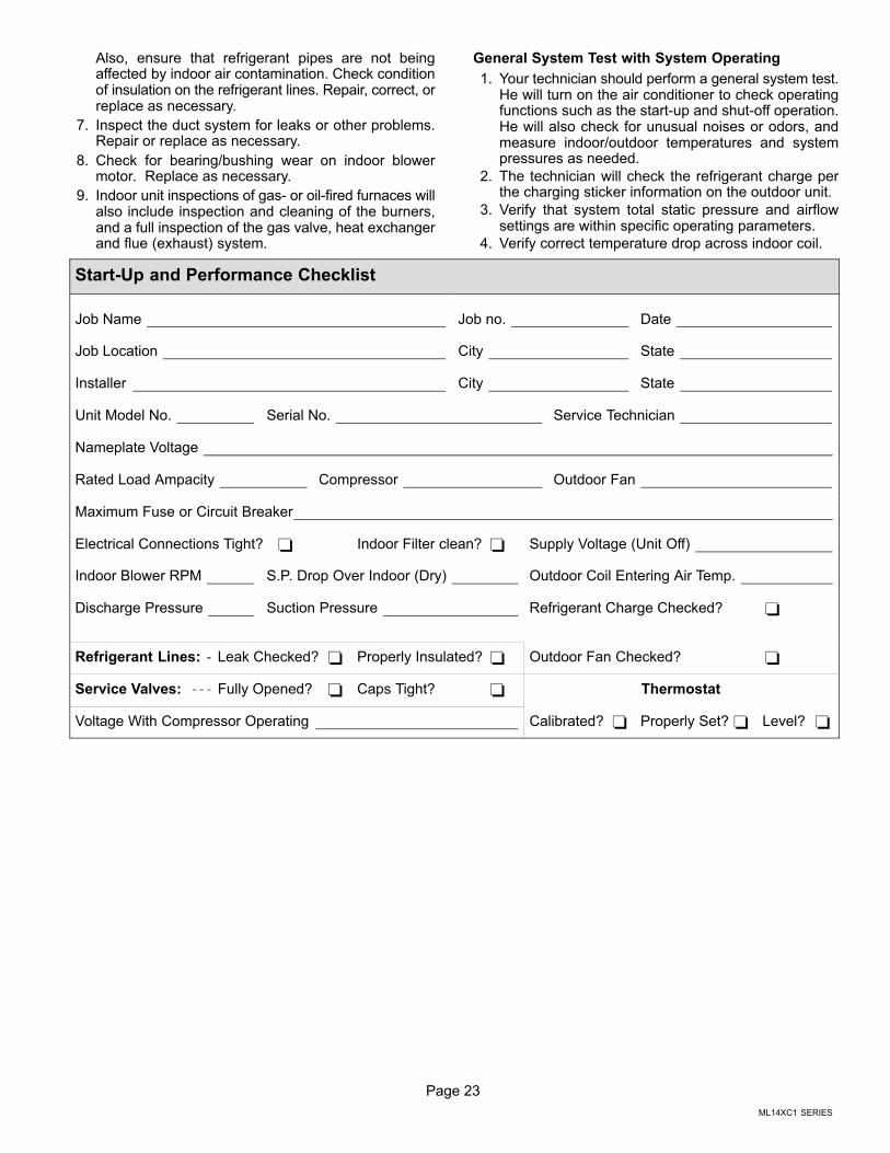
Start-Up and Performance Checklist
Job Name Job no. Date
Job Location City State
Installer City State
Unit Model No. Serial No. Service Technician
Nameplate Voltage
Rated Load Ampacity Compressor Outdoor Fan
Maximum Fuse or Circuit Breaker
Electrical Connections Tight? � Indoor Filter clean? � Supply Voltage (Unit Off)
Indoor Blower RPM S.P. Drop Over Indoor (Dry) Outdoor Coil Entering Air Temp.
Discharge Pressure Suction Pressure Refrigerant Charge Checked? �
Refrigerant Lines: Leak Checked? � Properly Insulated? � Outdoor Fan Checked? �
Service Valves: Fully Opened? � Caps Tight? � Thermostat
Voltage With Compressor Operating Calibrated? � Properly Set? � Level? �
Page 24
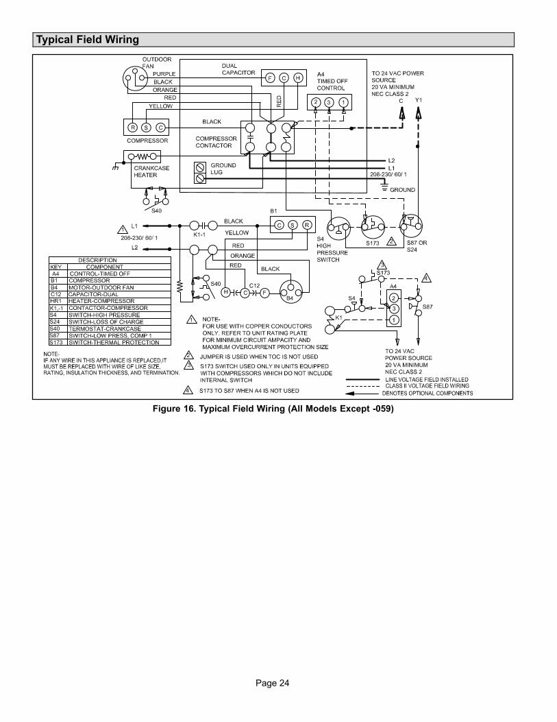
Typical Field Wiring
Figure 16. Typical Field Wiring (All Models Except -059)
Page 25
ML14XC1 SERIES
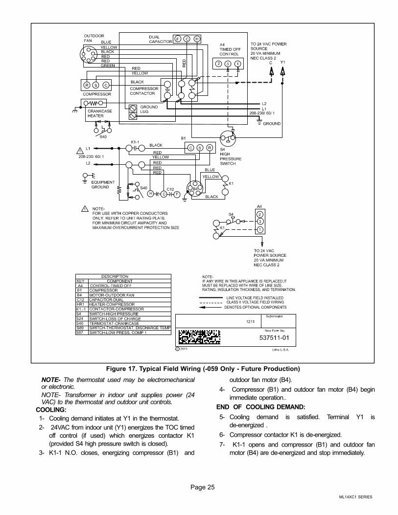
Figure 17. Typical Field Wiring (-059 Only - Future Production)
NOTE- The thermostat used may be electromechanicalor electronic.
NOTE- Transformer in indoor unit supplies power (24VAC) to the thermostat and outdoor unit controls.
COOLING:
1- Cooling demand initiates at Y1 in the thermostat.
2- 24VAC from indoor unit (Y1) energizes the TOC timed
off control (if used) which energizes contactor K1
(provided S4 high pressure switch is closed).
3- K1‐1 N.O. closes, energizing compressor (B1) and
outdoor fan motor (B4).
4- Compressor (B1) and outdoor fan motor (B4) begin
immediate operation..
END OF COOLING DEMAND:
5- Cooling demand is satisfied. Terminal Y1 is
de‐energized .
6- Compressor contactor K1 is de‐energized.
7- K1‐1 opens and compressor (B1) and outdoor fan
motor (B4) are de‐energized and stop immediately.
Page 26
Servicing Units Void of Charge
If the outdoor unit is void of refrigerant, clean the systemusing the procedure described below.
1. Leak check system using procedure outlined in figure12.
2. Evacuate the system using procedure outlined infigure 13.
3. Use nitrogen to break the vacuum and install a newfilter drier in the system.
4. Evacuate the system again using procedure outlinedin figure 13..
5. Weigh in refrigerant using procedure outlined underfigure 21.
Unit Start-Up
IMPORTANTIf unit is equipped with a crankcase heater, it should beenergized 24 hours before unit start-up to preventcompressor damage as a result of slugging.
1. Rotate fan to check for binding.
2. Inspect all factory- and field-installed wiring for looseconnections.
3. After evacuation is complete, open the liquid line andsuction line service valves to release the refrigerantcharge (contained in outdoor unit) into the system.
4. Replace the stem caps and tighten as specified inOperating Service Valves on page 5.
5. Check voltage supply at the disconnect switch. Thevoltage must be within the range listed on the unit'snameplate. If not, do not start the equipment until youhave consulted with the power company and thevoltage condition has been corrected.
6. Set the thermostat for a cooling demand. Turn onpower to the indoor indoor unit and close the outdoorunit disconnect switch to start the unit.
7. Recheck voltage while the unit is running. Power mustbe within range shown on the nameplate.
8. Check system for sufficient refrigerate using theprocedures that follow.
System Refrigerant
This section outlines procedures for:
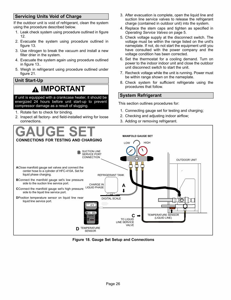
1. Connecting gauge set for testing and charging;
2. Checking and adjusting indoor airflow;
3. Adding or removing refrigerant.
TO LIQUIDLINE SERVICE
VALVETEMPERATURE
SENSOR
DIGITAL SCALE
REFRIGERANT TANK
TEMPERATURE SENSOR(LIQUID LINE)
MANIFOLD GAUGE SET
AClose manifold gauge set valves and connect thecenter hose to a cylinder of HFC-410A. Set forliquid phase charging.
BConnect the manifold gauge set's low pressureside to the suction line service port.
CConnect the manifold gauge set's high pressureside to the liquid line service port.
DPosition temperature sensor on liquid line nearliquid line service port.
OUTDOOR UNIT
CHARGE INLIQUID PHASE
CONNECTIONS FOR TESTING AND CHARGING
GAUGE SET
A
C
D
LOW HIGH
B SUCTION LINESERVICE PORTCONNECTION
Figure 18. Gauge Set Setup and Connections
Page 27
ML14XC1 SERIES
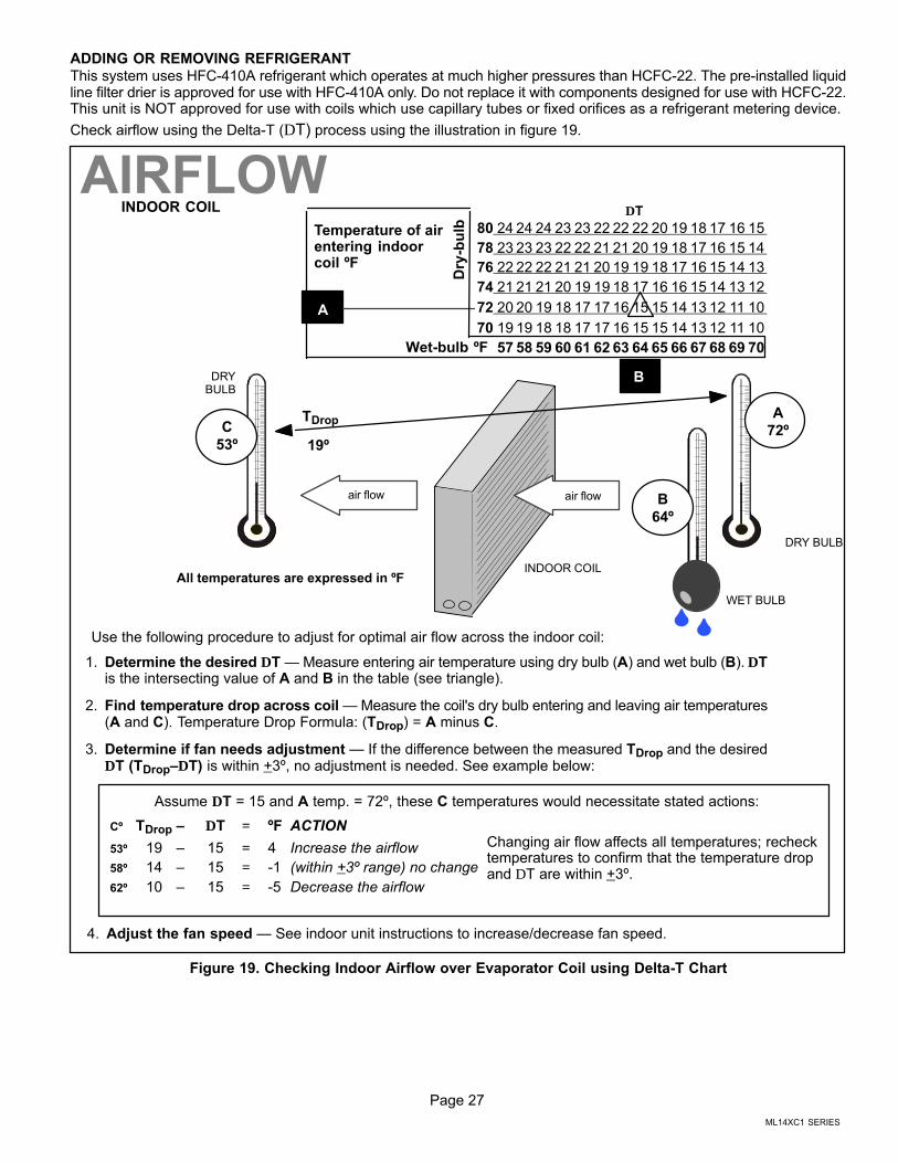
ADDING OR REMOVING REFRIGERANT
This system uses HFC-410A refrigerant which operates at much higher pressures than HCFC-22. The pre-installed liquidline filter drier is approved for use with HFC-410A only. Do not replace it with components designed for use with HCFC-22.This unit is NOT approved for use with coils which use capillary tubes or fixed orifices as a refrigerant metering device.
Check airflow using the Delta-T (DT) process using the illustration in figure 19.
Cº TDrop – DT = ºF ACTION
53º 19 – 15 = 4 Increase the airflow
58º 14 – 15 = -1 (within +3º range) no change
62º 10 – 15 = -5 Decrease the airflow
DT
80 24 24 24 23 23 22 22 22 20 19 18 17 16 15
78 23 23 23 22 22 21 21 20 19 18 17 16 15 14
76 22 22 22 21 21 20 19 19 18 17 16 15 14 13
74 21 21 21 20 19 19 18 17 16 16 15 14 13 12
72 20 20 19 18 17 17 16 15 15 14 13 12 11 10
70 19 19 18 18 17 17 16 15 15 14 13 12 11 10
57 58 59 60 61 62 63 64 65 66 67 68 69 70
Temperature of airentering indoorcoil ºF
INDOOR COIL
DRY BULB
DRYBULB
WET BULB
B
TDrop
19º
A
Dry
-bu
lb
Wet-bulb ºF
A
72º
B
64º
C
53º
air flowair flow
All temperatures are expressed in ºF
1. Determine the desired DT — Measure entering air temperature using dry bulb (A) and wet bulb (B). DTis the intersecting value of A and B in the table (see triangle).
2. Find temperature drop across coil — Measure the coil's dry bulb entering and leaving air temperatures(A and C). Temperature Drop Formula: (TDrop) = A minus C.
3. Determine if fan needs adjustment — If the difference between the measured TDrop and the desiredDT (TDrop–DT) is within +3º, no adjustment is needed. See example below:
4. Adjust the fan speed — See indoor unit instructions to increase/decrease fan speed.
Assume DT = 15 and A temp. = 72º, these C temperatures would necessitate stated actions:
AIRFLOW
Use the following procedure to adjust for optimal air flow across the indoor coil:
INDOOR COIL
Changing air flow affects all temperatures; rechecktemperatures to confirm that the temperature dropand DT are within +3º.
Figure 19. Checking Indoor Airflow over Evaporator Coil using Delta-T Chart
Page 28
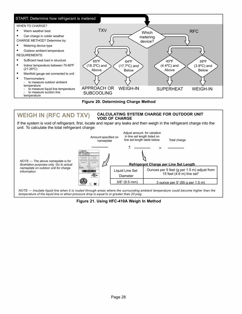
WHEN TO CHARGE?
� Warm weather best
� Can charge in colder weather
CHARGE METHOD? Determine by:
� Metering device type
� Outdoor ambient temperature
REQUIREMENTS:
� Sufficient heat load in structure
� Indoor temperature between 70‐80ºF(21-26ºC)
� Manifold gauge set connected to unit
� Thermometers:- to measure outdoor ambienttemperature- to measure liquid line temperature- to measure suction linetemperature
TXV RFC
APPROACH ORSUBCOOLING
WEIGH‐INSUPERHEAT
65ºF
(18.3ºC) and
Above
START: Determine how refrigerant is metered
39ºF
(3.8ºC) and
Below
Whichmeteringdevice?
WEIGH‐IN
64ºF
(17.7ºC) and
Below
40ºF
(4.4ºC) and
Above
Figure 20. Determining Charge Method
Liquid Line Set
Diameter
Ounces per 5 feet (g per 1.5 m) adjust from15 feet (4.6 m) line set*
3/8” (9.5 mm) 3 ounce per 5' (85 g per 1.5 m)
Refrigerant Charge per Line Set LengthNOTE — The above nameplate is forillustration purposes only. Go to actualnameplate on outdoor unit for chargeinformation.
NOTE — Insulate liquid line when it is routed through areas where the surrounding ambient temperature could become higher than thetemperature of the liquid line or when pressure drop is equal to or greater than 20 psig.
CALCULATING SYSTEM CHARGE FOR OUTDOOR UNITVOID OF CHARGE
If the system is void of refrigerant, first, locate and repair any leaks and then weigh in the refrigerant charge into theunit. To calculate the total refrigerant charge:
Amount specified onnameplate
Adjust amount. for variationin line set length listed online set length table below. Total charge
+ =
WEIGH IN (RFC AND TXV)
Figure 21. Using HFC-410A Weigh In Method
Page 29
ML14XC1 SERIES
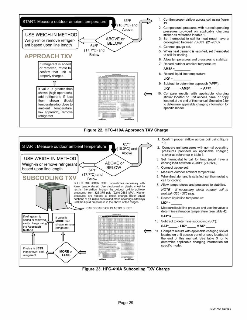
DO NOT CHARGE UNIT
(Results of charging at lowtemperatures not reliable)
START: Measure outdoor ambient temperature
USE WEIGH‐IN METHOD
Weigh‐in or remove refrigerant based upon line length
1. Confirm proper airflow across coil using figure19.
2. Compare unit pressures with normal operatingpressures provided on applicable chargingsticker as reference in table 1.
3. Set thermostat to call for heat (must have acooling load between 70‐80ºF (21-26ºC).
4. Connect gauge set.
5. When heat demand is satisfied, set thermostatto call for cooling.
6. Allow temperatures and pressures to stabilize.
7. Record outdoor ambient temperature:
AMBº =_________
8. Record liquid line temperature:
LIQº = __________
9. Subtract to determine approach (APPº):
LIQº_____ - AMBº _____ = APPº_____
10. Compare results with applicable chargingsticker located on unit access panel or copylocated at the end of this manual. See table 2 forto determine applicable charging information forspecific model.
ABOVE orBELOW
If value is greater than
shown (high approach),
add refrigerant; if less
than shown (liquid
temperature too close toambient temperature,
low approach), remove
refrigerant.
If refrigerant is added
or removed, retest to
confirm that unit is
properly charged.
64ºF
(17.7ºC) and
Below
65ºF
(18.3ºC) and
Above
APPROACH TXV
Figure 22. HFC-410A Approach TXV Charge
DO NOT CHARGE UNIT
(Results of charging at lowtemperatures not reliable)
START: Measure outdoor ambient temperature
USE WEIGH‐IN METHOD
Weigh‐in or remove refrigerantbased upon line length
BLOCK OUTDOOR COIL: [sometimes necessary withlower temperatures] Use cardboard or plastic sheet torestrict the airflow through the outdoor coil to achievepressures from 325-375 psig (2240-2585 kPa). Higherpressures are needed to check charge. Block equalsections of air intake panels and move coverings sidewaysuntil the liquid pressure is in the above noted ranges.
If value is
MORE than
shown, remove
refrigerant.
1. Confirm proper airflow across coil using figure19.
2. Compare unit pressures with normal operatingpressures provided on applicable chargingsticker as reference in table 1.
3. Set thermostat to call for heat (must have acooling load between 70‐80ºF (21-26ºC)
4. Connect gauge set
5. Measure outdoor ambient temperature
6. When heat demand is satisfied, set thermostat tocall for cooling
7. Allow temperatures and pressures to stabilize.
NOTE - If necessary, block outdoor coil to
maintain 325 - 375 psig.
8. Record liquid line temperature:
LIQº = ______
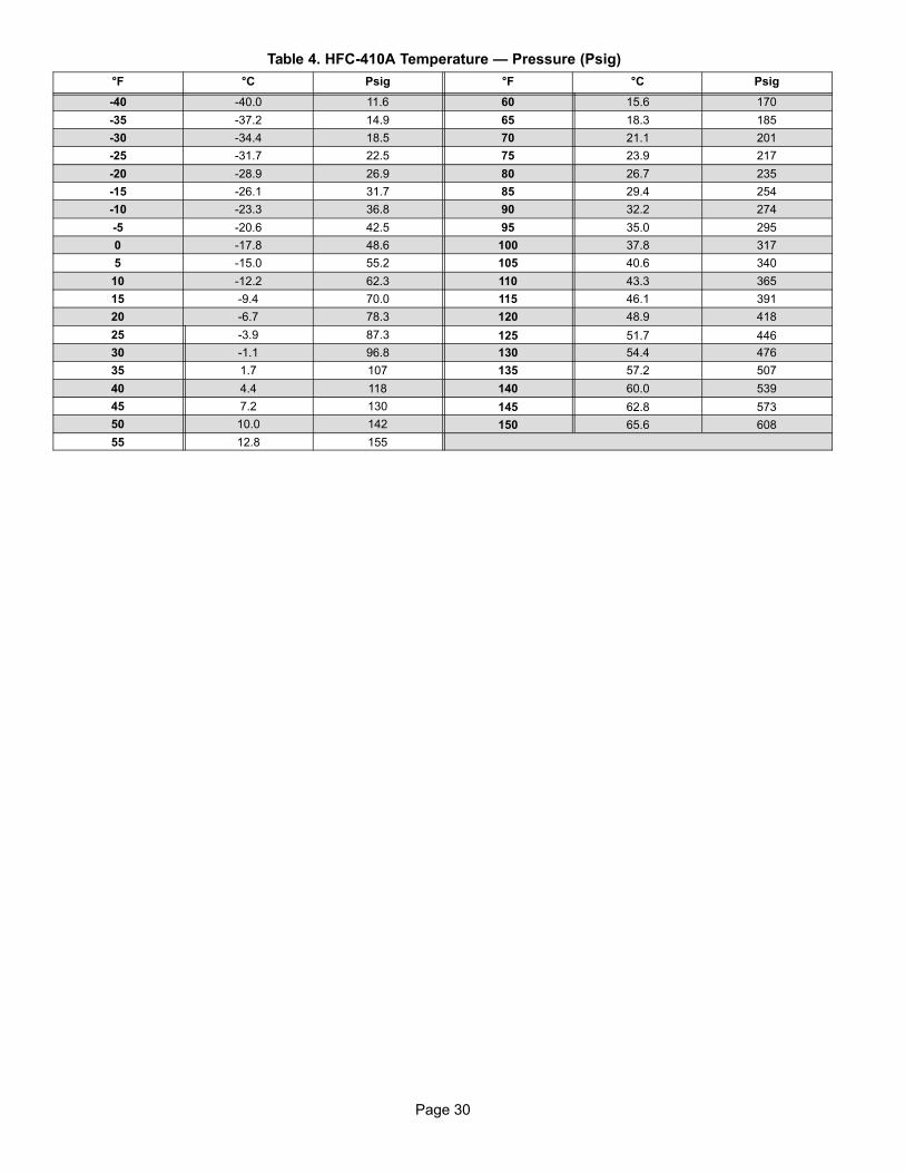
9. Measure liquid line pressure and use the value todetermine saturation temperature (see table 4):
SATº = ______
10. Subtract to determine subcooling (SCº):
SATº_____ - LIQº _____ = SCº _____
11. Compare results with applicable charging stickerlocated on unit access panel or copy located atthe end of this manual. See table 3 for todetermine applicable charging information forspecific model.
MORE orLESS
If value is LESS
than shown, add
refrigerant.
If refrigerant is
added or removed,
verify charge using
the Approach
Method.
ABOVE orBELOW
64ºF
(17.7ºC) and
Below
65ºF
(18.3ºC) and
Above
CARDBOARD OR PLASTIC SHEET
SUBCOOLING TXV
Figure 23. HFC-410A Subcooling TXV Charge
Page 30
Table 4. HFC-410A Temperature — Pressure (Psig)
°F °C Psig °F °C Psig
-40 -40.0 11.6 60 15.6 170
-35 -37.2 14.9 65 18.3 185
-30 -34.4 18.5 70 21.1 201
-25 -31.7 22.5 75 23.9 217
-20 -28.9 26.9 80 26.7 235
-15 -26.1 31.7 85 29.4 254
-10 -23.3 36.8 90 32.2 274
-5 -20.6 42.5 95 35.0 295
0 -17.8 48.6 100 37.8 317
5 -15.0 55.2 105 40.6 340
10 -12.2 62.3 110 43.3 365
15 -9.4 70.0 115 46.1 391
20 -6.7 78.3 120 48.9 418
25 -3.9 87.3 125 51.7 446
30 -1.1 96.8 130 54.4 476
35 1.7 107 135 57.2 507
40 4.4 118 140 60.0 539
45 7.2 130 145 62.8 573
50 10.0 142 150 65.6 608
55 12.8 155