Embed Size (px)
Citation preview

INSTALLATION AND SERVICINGINSTRUCTIONS
ANDUSER'S INFORMATION MANUAL
**INSTALLER — AFFIX THIS INSTRUCTIONPACKET ADJACENT TO THE FURNACE.
**HOMEOWNER — RETAIN THESEINSTRUCTIONS FOR FUTURE REFERENCE.
INSTRUCTIONS D'ENTRETIEN ETINSTALLATION
ETMANUEL DE L'USAGER
**INSTALLATEUR -- PLACEZ LA POCHETTED'INSTRUCTIONS À COTÉ DU GÉNÉRATEUR
D'AIR CHAUD.
**PROPRIÉTAIRE -- CONSERVEZ CESINSTRUCTIONS POUR Y RÉFÉRER PLUS TARD.
LITERATURE BOOKLET NO. 20537001ISSUE 0222
20536901

Owner Record
Furnace Model # Serial # Installation Date
INSTALLED BY:
Dealer
Address
Telephone # License #
Contact Person
Other Equipment Installed:
Equipment Type
Model # Serial # Installation Date
Equipment Type
Model # Serial # Installation Date
Equipment Type
Model # Serial # Installation Date
WHEN FRENCH IS REQUIRED!
ATTENTION: MR. INSTALLER OR HOMEOWNER
TO OBTAIN INSTALLATION INSTRUCTIONS, USER'S INFORMATION MANUAL AND FURNACEMARKINGS IN FRENCH CONSULT WITH YOUR DEALER OR LOCAL DISTRIBUTOR:
HAVE AVAILABLE THE MODEL NO. AND SERIAL NO. LOCATED ON THE UNIT RATING PLATE TOINSURE THE CORRECT FRENCH INSTRUCTION PACKET.
POUR OBTENIR DE LA DOCUMENTATION EN FRANÇAIS!
À L'ATTENTION DE L'INSTALLATEUR OU DU PROPRIÉTAIRE
POUR OBTENIR LES INSTRUCTIONS D'INSTALLATION, LE MANUEL DE L'USAGER ET LESMARQUAGES EN FRANÇAIS, CONSULTEZ VOTRE MARCHAND OU LE DISTRIBUTEUR DE VOTRE RÉGION:
AYEZ EN MAIN LE MODELE ET LE NUMÉRO DE SÉRIE INDIQUÉS SUR LA PLAQUE SIGNALÉTIQUEDE L'APPAREIL POUR OBTENIR LA POCHETTE D'INSTRUCTIONS EN FRANÇAIS APPROPRIÉE.

20532901 Issue 0215 Page 1 of 6
USER'S INFORMATION MANUALGas-Fired Furnace
READ ALL INSTRUCTIONS IN THIS MANUAL AND RETAIN THIS AND ALL ADDITIONAL INSTRUCTIONS FOR FUTURE REFERENCE.
Congratulations...
...you have one of the most modern gas furnaces made.Your unit has been carefully selected to keep you warmand comfortable during the winter months. It will deliversuperb performance with only minimal help from you.
To keep your operating costs low and to eliminateunnecessary service calls, we have provided a fewguidelines. These guidelines will help you understandhow your gas furnace operates and how to maintain it soyou can get years of safe and dependable service.
GAMA Certified
The Gas Appliance Manufacturers Association (GAMA)symbol verifies that Annual Fuel Utilization Efficiency(AFUE) ratings for our gas furnaces have been derivedfrom U.S. Government standard tests.
CSA International Design Certified
The CSA International symbols on each nameplate isyour assurance that your furnace design meets nationallyrecognized standards for safety and performance.
— Do not store or use gasoline or otherflammable vapors and liquids in thevicinity of this or any other appliance.
— What to do if you smell gas:
• Do not try to light any appliance. • Do not touch any electrical switch; do
not use any phone in your building. • Leave the building immediately. • Immediately call your gas supplier from
a neighbor's phone. Follow the gassupplier's instructions.
• If you cannot reach your gas supplier,call the fire department.
— Installation and service must beperformed by a qualified installer,service agency or the gas supplier.
FIRE OR EXPLOSION HAZARD
Failure to follow safety warnings exactlycould result in serious injury death orproperty damage.
TABLE OF CONTENTS
SAFETY . . . . . . . . . . . . . . . . . . . . . . . . . . 2
OPERATING YOUR FURNACE . . . . . . . . . . . 2Lighting Instructions . . . . . . . . . . . . . . . . . 2Temperature Control . . . . . . . . . . . . . . . . . 3Fan Operation . . . . . . . . . . . . . . . . . . . . . 3
MAINTENANCE OF YOUR FURNACE . . . . . . 4Periodic Inspections . . . . . . . . . . . . . . . . . 4Cleaning/Replacing the Filter . . . . . . . . . . . 5Parts Replacement Guide . . . . . . . . . . . . . 6

For your safety -
20532901 Issue 0215 Page 2 of 6
Read before operating
Here are a few "Do's and Don'ts"
• Do become familiar with the instructions.
• Do check to see that your home has adequateinsulation, weatherstripping, caulking, and stormwindows. Elimination of infiltration of outside air anddrafts can save up to 40% of your fuel bill.
• Do consider adding a humidifier to your heatingsystem. Higher indoor humidity slows evaporationof perspiration, making the home seem warmer.
• Don't waste fuel by setting your thermostat too high.Energy conservation experts recommend a daytimethermostat setting of 68°F, with a lower setting atnight.
• Don't turn off the furnace when you expect to beaway for more than a day. Instead, lower thethermostat setting a few degrees. You can thenrestore normal comfort level quickly and save fueltoo.
• Don't block registers with furniture.
• Don't put a lamp, TV, or radio too near yourthermostat. This will cause it to give a false reading.
If you do not follow these instructionsexactly, a fire or explosion may result,causing property damage, personal injury,or loss of life.
These furnaces are equipped with an ignition devicewhich automatically lights the burners. Do not try tolight the burners by hand.
Before operating, smell around the furnace area for gas.Be sure to smell next to the floor because some gas isheavier than air and will settle to the lowest point. Referto "What to do if you smell gas" on page 1 if the odorof gas is present.
Use only your hand to adjust the gas control switch;never use tools. If the switch will not move by hand,don't try to repair it, call a qualified service technician.Force or attempted repair may result in a fire orexplosion.
Do not use this furnace if any part has been under water.
A flood-damaged furnace is extremely dangerous.Attempts to use the furnace can result in fire or explosion.A qualified service agency should be contacted to inspectthe furnace and to replace all gas controls, control systemparts, electrical parts that have been wet or the furnaceif deemed necessary.
The furnace area must be kept clear andfree of combustible materials, gasoline, andother flammable vapors and liquids.Failure to do so could cause actions thatmay result in property damage, personalinjury, or loss of life.
Operating Your Furnace
Lighting Instructions
1. STOP! Read the previous safety information.
2. Set the thermostat to the lowest setting.
3. Turn off all electric power to the furnace.
4. Remove the burner compartment access panel.
5. This appliance is equipped with an automatic ignition.device. Do not try to light the burners by hand.
6. Move the gas control switch to "OFF" (see Figure 1).
Figure 1Gas Control Diagram
7. Wait 5 minutes to clear out any gas, then smell forgas (including at the bottom of the unit near theground). If you smell gas, stop and follow thedirections in "What to do if you smell gas" on page1. If you don't smell gas, continue to next step.
8. Move the gas control switch to "ON".
9. Replace the burner compartment access panel.
10. Turn on all electric power to the furnace.

11. Set the thermostat to the desired setting.
20532901 Issue 0215 Page 3 of 6
12. If the furnace will not operate, follow the instructionsin "To Turn Off Gas to Furnace" and call yourservice technician or gas supplier.
To Turn Off Gas to Furnace
1. Set the thermostat to the lowest setting.
2. Turn off all electric power to the furnace if service isto be performed.
3. Remove the burner compartment access panel.
4. Move the gas control switch to "OFF" (see Figure 1).Do not force.
5. Replace the burner compartment access panel.
Temperature Control
There are many types and styles of thermostats. Yoursmay look different from the one pictured in Figure 2,depending on the type of thermostat and whether coolingwas installed with the system. However, almost allthermostats perform the same basic functions describedin the following section.
Figure 2
Thermostat Operation
There are two (2) switches located on the thermostat (seeFigure 2). One switch controls the heating and cooling (ifapplicable) functions. The other switch is for "FAN"operation, either continuous or automatic. On thethermostat is the temperature range for the heatingtemperature and the cooling temperature desired.
To put the system into operation, push the switch toeither "HEAT" or "COOL" position. After you have chosenthe type of operation you desire, move the thermostat dialor lever to select the temperature you would like thesystem to maintain.
Fan Operation
You may wish to increase your comfort by setting yoursystem for continuous air circulation of the indoor air.The fan switch on the thermostat permits you to do this.
With the switch in the "ON" position the fan will operatecontinuously. "AUTO" position gives fan operation onlywhen the unit is in either heating or cooling.
What to do if your unit is not heating properly
If your furnace is operating but fails to provide completecomfort, check the following before calling for service:
1. Be sure the thermostat setting is correct.
2. Check to see if the filter is clean.
3. Be sure air can circulate freely throughout your home.Do not block supply registers or return grilles withfurniture or rugs.
And if you also have cooling...
4. Keep surface of the outdoor coil free from dirt, lint,paper, or leaves.
5. Check and clean indoor coil, if necessary. (Thischeck should be made at the start of each coolingseason by your service technician).
What to do if your unit fails to operate
1. Be sure the main switch that supplies power to thefurnace is in the "ON" position.
2. Replace any burned-out fuses or reset circuitbreakers.
3. Be sure the thermostat is properly set.
4. If the furnace still does not start, call your servicetechnician.
Should the gas supply fail to shut off or ifoverheating occurs, shut off the gas valveto the furnace before shutting off theelectrical supply.

Maintenance Of Your Furnace
20532901 Issue 0215 Page 4 of 6
Always shut off all power to the unit beforeattempting any of the followingmaintenance procedures. Failure to do somay result in personal injury.
There are routine maintenance steps you should take tokeep your furnace operating efficiently. This maintenancewill assure longer life, lower operating costs, and fewerservice calls. In addition to the maintenance procedureslisted in this manual, there are also other service andmaintenance procedures that require the skills of aservice person who has specialized tools and training.(See "Servicing the Furnace" section of the Installationand Servicing part of this booklet.) Personal injury canresult if you are not qualified to do this work. Pleasecall your dealer when service is needed.
Cleaning
The cabinet of the furnace can be cleaned with soap andwater. Grease spots can be removed with a householdcleaning agent. The cabinet can be kept attractive bypolishing with automotive wax at least twice a year.
Installations Around Insulation
Insulating materials may be combustible. Therefore, afurnace installed in an attic or other insulated space mustbe kept free and clear of insulating materials. Make sureto examine the furnace area when the furnace is installedor additional insulation has been added.
Periodic Inspections
Your gas furnace is designed to give many years ofefficient, satisfactory service. However, the varied airpollutants commonly found in most areas can affectlongevity and safety. Chemicals contained in everydayhousehold items such as laundry detergents, cleaningsprays, hair sprays, deodorizers, and other productswhich produce airborne residuals may have an adverseaffect upon the metals used to construct your appliance.
It is important that you conduct periodic physicalinspections of your appliance, paying special attention tothe gas burner and the flue outlet from the furnace.These components are located at the front of the unit. Aflashlight will be useful for these inspections. Make oneinspection prior to the beginning of the heating seasonand another during the middle.
Should you observe unusual amounts of any of thefollowing conditions, it is important that you call your
authorized dealer at once to obtain a qualified serviceinspection:
• Rust, flakes, or other deposits• Coatings• Corrosion
Even if no unusual rust or other conditions are observed,it is recommended that the furnace be inspected andserviced at least once per year by a qualified servicetechnician. Regular inspection and plannedmaintenance will assure many years of economicalperformance from your gas furnace.
Combustion Air
Adequate combustion and ventilation airmust reach your gas furnace to provide forproper and safe operation. Do not block orobstruct air openings on the furnace, airopenings communicating with the area inwhich the furnace is installed and thespacing around the furnace. Anyobstruction of this airflow can cause anunsafe condition which may result in deathor permanent injury.
Furnaces located in a closet, alcove, or utility room musthave provision for adequate air supply by means of upperand lower grilles in the door, or by the introduction ofoutside air, or both. National Fuel Gas Code, ANSIZ223.1 (latest edition), CAN/CGA B149.1 & .2 InstallationCodes (latest edition), and local requirements aregenerally alike. However, local codes take precedence.
Venting and Furnace Support
Venting of this furnace must comply with our publishedinstructions. Be sure the installer has followed theserequirements. If not, you should request the installer tocomply as soon as possible.
For your safety, please note the following:
1. 80% furnaces may be common vented with anotherappliance in certain circumstances. Refer to theinstallation instructions and Category I VentingTables, National Fuel Gas Code ANSI Z223.1 (latestedition), for proper installation guidelines. In Canada,see CAN/CGA B149.1 & .2 Installation Codes (latestedition).
2. This furnace is not designed for use with a ventdamper. Use of such a device will not improve theefficiency of this furnace.

The vent from your furnace may rise vertically and
20532901 Issue 0215 Page 5 of 6
terminate above the roof. When horizontal venting an80% furnace, an approved sidewall venter must be used.Refer to the installation instructions for further informationon horizontal venting of an 80% furnace.
Make sure all flue product carrying areas and materialsexternal to the furnace (i.e. vent terminals, etc..) are clearand free of any obstruction, slope upward, and have noholes or leaks.
Check to see that the furnace cabinet is sound and firmlysupported, without sagging. There should be no cracksor gaps between the furnace and the base or floor, whichwould permit entry of unfiltered air.
It is important that the outside area where the ventterminates is kept clear of any obstructions which mightblock or impede the venting of the furnace. Shouldventing become blocked at anytime, your furnace isequipped with a special safety control to preventoperation of the furnace until the condition has beencorrected. Contact your dealer if you desire moreinformation about this safety feature.
Should any unusual conditions be observed during yourinspections, call an authorized service dealer immediately.
For proper venting terminations, see the InstallationInstructions furnished with the furnace.
Return Air
Ascertain that all return air duct connections are tight andsealed to the furnace cabinet and that all return air grillesor registers are located outside the space containing thefurnace.
Cleaning/Replacing the Filter
It is very important to clean or replace the air filterregularly. Dirty filters are the most common cause ofinadequate heating or cooling performance and cansharply increase the operational costs of your unit. Insome cases, they can double the cost. The air filtershould be inspected at least every 6 weeks andcleaned or replaced as required.
Your furnace may use either a disposable filter or apermanent filter. The type of filter may be indicated on alabel attached to the filter. If a disposable filter is used,replace with the same type and size. If a permanent filteris used, clean filter and place back in furnace. To cleana permanent filter, shake filter to remove excess dirtand/or use a vacuum cleaner. Wash filter in soap ordetergent water and replace after filter is dry. Permanentfilters do not need to be oiled after washing.
Permanent filters may be replaced with disposable filters.
Refer to Table 1 when selecting the proper size andquantity of disposable filter.
If your air distribution system has a central return air filter-grille, you do not need a filter in your furnace. Clean thefilter-grille the same way permanent filters are cleaned.
Table 1EXTERNAL FILTER RACK SIZE
BTUINPUT
FILTERSIZE
50,000 13 X 23
75,000 13 X 23
100,000 16½ X 26
125,000 20 X 23
Safety Interlock Switch
The blower compartment door on your high efficiency gasfurnace is equipped with a safety interlock switch that willautomatically shut off your complete system (includingblower) once the door is removed. This is for yourpersonal safety. Be sure to check your furnace for properoperation once the door or panel has been replaced.
If the system does not operate once the panel has beenreplaced, try removing and replacing it once again. If thefurnace still does not operate, call your dealer for service.
Rollout Switch
This unit is equipped with a manual reset hightemperature sensor or rollout switch. In the unlikely eventof a sustained main burner flame rollout, the rollout switchwill shut off the flow of gas by closing the main gas valve.The switch is located inside the gas burner area. Flamerollout can be caused by blockage of the power ventsystem, a blocked heat exchanger, or improper gaspressure or adjustment. If this event occurs, the unit willnot operate properly. The gas supply to the unit shouldbe shut off and no attempt should be made to place itin operation. The system should be inspected by aqualified service technician.
Lubrication
Lubrication of the bearings in the circulating air blowermotor and the combustion blower motor is notrecommended.
Burner Flame
While the furnace is in operation, observe the mainburner flames. Compare these observations to Figure 3to determine if proper flame adjustment is present. Ifyour observations indicate improper flame adjustment, callyour authorized service dealer for service.

20532901 Issue 0215 Page 6 of 6
Figure 3
Do not attempt to adjust flame! Your servicerepresentative will perform this adjustment correctly.
Warranty Procedure
When warranty parts are required:1. Be prepared to furnish the following information:
a. Purchaser's nameb. Complete model number, serial number, and
date of installation.c. An accurate description of the problem or
defective parts.2. Contact your dealer or distributor.
Keep this User's Information Manual (includingWarranty) and proof of purchase for your records.Your warranty is determined from your date ofinstallation. If proof of your date of installation is notsupplied, the warranty will be based on themanufacture date code.
Failure to follow the correct warranty procedure couldresult in disallowance of warranty claim.
PARTS REPLACEMENT INFORMATION GUIDE
CASING GROUP GAS CONTROL GROUP BLOWER GROUP Top Panel Manifold Blower Assembly Bottom Panel Manifold Retention Plate Blower Housing Front & Back Left Panel Burner Blower Motor Front Center Panel Orifice Blower Wheel Back Center Panel Gas Valve Capacitor Back Blower Panel Blower Cutoff Blower Door Blower Support Corner Post
ELECTRICAL GROUP HEAT EXCHANGER GROUP INDUCER GROUP Control Box Primary Heat Exchanger Pressure Switch Limit Switch Flue Box Inducer Blower & Motor Fan Timer Control Board Burner Box Panel Rollout Switch Transfer Tube Transformer Burner Inlet Plate
TO OBTAIN INFORMATION ON PARTS: Consult your installing dealer or classified section of your localtelephone directory under the "Heating Equipment" or "Air Conditioning Contractors & Systems" headings for dealer listingor see the first page of the installation instruction section of this manual for the name and address to contact.
Have available the Model No. and Serial No. located on the unit rating label located on the furnace to insure correctreplacement part.
WARNING: Improper installation, adjustment, alteration, service or maintenance can cause personal injury or propertydamage. Consult a qualified installer, service agency, or your local gas supplier for information or assistance.

AFFIX LABEL HERE
INSTALLATION AND SERVICING INSTRUCTIONSHORIZONTAL GAS-FIRED
NON-CONDENSINGWARM AIR FURNACE
Issue 0222
TABLE OF CONTENTS
Safety . . . . . . . . . . . . . . . . . . . . . . . . . . . . . . . . . . . . . . . . . . . 2
Furnace Specifications . . . . . . . . . . . . . . . . . . . . . . . . . . . . . . . 3
Introduction . . . . . . . . . . . . . . . . . . . . . . . . . . . . . . . . . . . . . . . 6
Location/Placement . . . . . . . . . . . . . . . . . . . . . . . . . . . . . . . . . . 6
Air for Combustion & Ventilation . . . . . . . . . . . . . . . . . . . . . . . . 8
Ducting . . . . . . . . . . . . . . . . . . . . . . . . . . . . . . . . . . . . . . . . . . 9
Venting . . . . . . . . . . . . . . . . . . . . . . . . . . . . . . . . . . . . . . . . . . 10
Electrical Connections . . . . . . . . . . . . . . . . . . . . . . . . . . . . . . . . 13
Gas Connections . . . . . . . . . . . . . . . . . . . . . . . . . . . . . . . . . . . 13
Theory of Operation . . . . . . . . . . . . . . . . . . . . . . . . . . . . . . . . . 15
Start-Up Operation & Checkout . . . . . . . . . . . . . . . . . . . . . . . . . 16
Servicing The Furnace . . . . . . . . . . . . . . . . . . . . . . . . . . . . . . . 20
Sequence of Operation . . . . . . . . . . . . . . . . . . . . . . . . . . . . . . . 22
Trouble Shooting Guide . . . . . . . . . . . . . . . . . . . . . . . . . . . . . . . 23
Wiring Diagram . . . . . . . . . . . . . . . . . . . . . . . . . . . . . . . . . . . . . 24
RETAIN THESE INSTRUCTIONS FOR FUTURE REFERENCE
Do not store or use gasoline or otherflammable vapors and liquids in thevicinity of this or any other appliance.
Installation and service must be performedby a qualified installer, service agency orthe gas supplier. Installation by anunqualified person may lead to equipmentdamage and/or a hazardous conditionwhich may cause bodily injury and harmand, as such, at the sole discretion of themanufacturer, the entire warranty may bevoided and be of no further force andeffect.
WHAT TO DO IF YOU SMELL GAS:
• Do not try to light any appliance.• Extinguish any open flame.• Do not touch any electrical switch; do
not use any phone in your building.• Immediately call your gas supplier from
a neighbor's phone. Follow the gassupplier's instructions.
• If you cannot reach your gas supplier,call the fire department.
20531501 Issue 0222 Page 1 of 24

SAFETY
The following is a list of safety precautions and their locations in this manual.
These safety rules and precautions must be followed when installing this furnace.
1. Use only with type of gas approved for this furnace. Refer to the furnace ratingplate.
2. Install this furnace only in a location and position as specified in TheLocation/Placement Section on page 6 of these instructions.
3. Provide adequate combustion and ventilation air to the furnace space asspecified in Air for Combustion and Ventilation section on page 8 of theseinstructions.
4. Combustion products must be discharged outdoors. Connect this furnace to anapproved vent system only, as specified in Venting on page 11 of theseinstructions.
5. Never test for gas leaks with an open flame. Use a commercially availablesoap solution made specifically for the detection of leaks to check allconnections, as specified in The Gas Connection section on page 13 of theseinstructions.
6. Always install furnace to operate within the furnace's intended temperature-riserange with a duct system which has an external static pressure within theallowable range, as specified in Furnace Specifications on page 3 of theseinstructions. See furnace rating plate.
7. When a furnace is installed so that supply ducts carry air circulated by thefurnace to areas outside the space contining the furnace, the return air shallalso be handled by duct(s) sealed to the furnace casing and terminating outsidethe space containing the furnace. See page 9 for Ducting.
8. A gas-fired furnace for installation in a residential garage must be installed asspecified in The Location / Placement section on page 7 of these instructions.
9. The furnace is not to be used for temporary heating of buildings or structuresunder construction. As noted on page 6 under Introduction.
20531501 Issue 0222 Page 2 of 24

FURNACE SPECIFICATIONS
20
53
15
01
Issue
0
22
2 P
ag
e 3
of 2
4
MODEL
UNIT DIMENSIONS DUCT SUPPLYOPENING
FLUEDIAM.
BLOWERDOOR
MAX. OVERCURRENT
PROTECTION
MAX.UNIT
AMPS
ELECTRICALSUPPLY MIN. WIRE
SIZE(AWG)
TEMPERATE-RISERANGE
NETWEIGHT
LBSLENGTH WIDTH HEIGHT
A B C D E F G H
B050A3B 50 13 1/2 23 1/8 11 5/8 21 3/8 4 2 0 15 8.3 14 30 - 60 112
B075A3B 50 13 1/2 23 1/8 11 5/8 21 3/8 4 3 0 15 9.9 14 40 - 70 121
B075A4B 50 13 1/2 23 1/8 11 5/8 21 3/8 4 3 1 15 11.7 14 30 - 60 121
B100A4B 50 17 23 1/8 15 1/8 21 3/8 4 4 0 15 11.7 14 40 - 70 141
B100A5B 50 17 23 1/8 15 1/2 21 3/8 4 4 1 20 13.1 12 30 - 60 141
B125A5B 50 20 1/2 23 1/8 18 5/8 21 3/8 4 5 0 15 11.7 14 40 - 70 161

FURNACE BLOWER SPECIFICATIONS AND AIR FLOW DATA
BLOWERSYSTEM
BLOWERSPEED
EXTERNAL STATIC (IN. W.C.)
0.1 0.2 0.3 0.4 0.5 0.6 0.7 0.8 0.9 1.0
B050A3B(10X6 WHEEL)
(1/3HP MOTOR)
LOW 615 605 595 580 555 525 490 445 395 340
MED 925 940 945 935 915 890 850 800 735 665
HIGH 1570 1550 1515 1470 1415 1340 1255 1160 1050 925
B075A3B LOW 1005 975 940 905 870 835 795 750 705 665
(10X6 WHEEL) MED 1405 1340 1280 1215 1150 1085 1015 945 870 795
(1/3HP MOTOR) HIGH 1755 1695 1635 1560 1475 1385 1285 1170 1045 915
B075A4B LOW 1415 1405 1390 1355 1315 1255 1190 1105 1015 905
(10X6 WHEEL) MED 1745 1695 1635 1565 1485 1405 1310 1205 1095 980
(1/2HP MOTOR) HIGH 1915 1845 1765 1680 1590 1495 1390 1285 1165 1045
B100A4B LOW 1260 1235 1205 1175 1140 1105 1065 1025 985 940
(12X9 WHEEL) MED 1470 1465 1465 1455 1435 1410 1375 1335 1295 1240
(1/2HP MOTOR) HIGH 1845 1825 1795 1755 1715 1665 1610 1550 1485 1410
B100A5B LOW 1380 1365 1340 1305 1265 1215 1160 1090 1015 925
(12X9 WHEEL) MED 1795 1780 1755 1720 1670 1610 1540 1455 1360 1255
(3/4HP MOTOR) HIGH 2385 2330 2265 2195 2105 2015 1910 1795 1670 1535
B125A5B LOW 1195 1155 1110 1065 1020 970 915 860 805 750
(12X12 WHEEL) MED 1480 1455 1425 1392 1355 1315 1272 1225 1174 1120
(1/2HP MOTOR) HIGH 1825 1805 1785 1760 1735 1705 1675 1640 1600 1560
NOTES:1. Air flow values in cubic feet per minute (CFM), rounded to nearest five (5) CFM.2. Data taken without filters in place or A/C evaporator in place.
When operating the furnace in the heating mode, the static pressure and the temperature rise(supply air temperature minus return air temperature) must be within those limits specified on therating label. Failure to follow this warning could lead to severe furnace damage.
Turn OFF all gas and electrical power to furnace before performing any maintenance or serviceon unit. (Unless specific test requires gas and electrical supplies.) Failure to take this precautionmay result in personal injury due to electrical shock or uncontrolled gas leakage.
20531501 Issue 0222 Page 4 of 24

FURNACE WIRING SPECIFICATIONS
20531501 Issue 0222 Page 5 of 24

The furnace cabinet must have an uninterrupted or unbroken electrical ground to minimizepersonal injury if an electrical fault should occur. The unit must also be electrically grounded inaccordance with local codes, or in the absence of local codes, with the latest edition of the (U.S.)National Electrical Code ANSI/NFPA No. 70 or CSA Standard C22.1; Part 1 Canadian ElectricalCode, if an external electrical source is utilized. DO NOT use gas piping as an electrical ground.
INTRODUCTION
This furnace is design certified by CSA International as a Category I furnace using air from inside the structure forcombustion. The combustion system is fan-assisted which means it is equipped with an integral mechanical means to drawproducts of combustion through the heat exchanger.
It is shipped as a packaged unit, complete with burners and controls, and requires a line voltage (115V) connection tothe junction box, a thermostat hook-up as per the wiring diagram and a gas line connection. This furnace can be installedin either horizontal right or horizontal left airflow positions. The design of this furnace is NOT CSA Certified forinstallation in recreation vehicles, in manufactured (mobil) homes, outdoors or for temporary construction heating.
This furnace has been designed to interface with split system cooling equipment (approved by a nationally recognizedtesting laboratory) so as to provide "year round air conditioning". The blower has been sized for both heating and coolingand the furnace controls include a cooling fan relay.
The furnace installation must conform with local building codes or in the absence of local codes, with the latest editionof the (U.S.) National Fuel Gas Code ANSI Z223.1 (NFPA-54) or Canadian Natural Gas and Propane Installation CodesCSA B149.1.
For complete information on installation standards consult the (U.S.) National Fuel Gas Code, obtainable from theNational Fire Protection Association, Inc., Batterymarch Park, Quincy, MA 02269 or the American Gas Association, 1515Wilson Boulevard Arlington, VA 22209 or the Canadian installation codes obtainable from Canadian Standards Association,178 Rexdale Boulevard, Etobicoke, Ontario, Canada M9W 1R3.
This furnace is designed for minimum continuous return-air temperature of 60°F dB or intermittent operation down to55°F dB such as when used with a night setback thermostat. Return-air must not exceed a maximum continuoustemperature of 85°F dB.
These instructions are written for individual residential installation only. For multi-unit installation, pleasecontact manufacturer for recommendations.
LOCATION / PLACEMENT
Site Selection: This furnace may be located in an attic, closet, basement, crawl space, alcove or suspended from theceiling of a utility room or basement. Select a location that will meet all requirements for safety,clearances, ventilation and combustion air, ductwork design, gas piping, electrical wiring and venting.
Clearances: The following minimum clearances, or greater, must be provided between the furnace and adjacentconstruction.
TABLE 1 MINIMUM INSTALLATION CLEARANCES"HORIZONTAL" POSITION
Suitable for attic, alcove or closet installation† on combustible flooring at minimum clearance from adjacent construction not lessthan the following:* Line contact only permissible between lines formed by intersection of the top and two sides of the furnace jacket and building joist,studs, or framing.
Top Sides Back Front Vent
2" 6" 6" 6" ** 6" with single wall vent
2" 6" 6" 6" ** 1" with B1 vent
† For closet installation see Air for Combustion and Ventilation.** From End of Inducer Motor
20531501 Issue 0222 Page 6 of 24

Failure to comply with all of the clearanceswill create a fire hazard.
The furnace should also be located as near to thecenter of the air distribution system as possible, andshould be installed level.
This furnace may be installed on non-combustibleflooring or on wood flooring, however, it must not beinstalled directly on carpeting, tile or any othercombustible material.
Line contact is only permissible between lines formedby the intersection of the furnace top, the front and backsides, and building joists, studs or framing (See Figure 1).
Figure 1HORIZONTAL LINE CONTACT
Furnace must not lean back. It must be level ortilt up to 2° to the front. (See Figure 1.)
A clearance of at least 30" should be provided at thefront of the unit for servicing. For attic installations, thepassageway and servicing area adjacent to the furnaceshould be floored.
If the furnace is to be installed in a crawl space,consult local codes. (Use of a concrete pad 1" to 2" thickis recommended.)
If the furnace is to be suspended from the ceiling, itwill be necessary to use steel pipe straps around eachend of the furnace. These straps should be attached tothe furnace with sheet metal screws and to the rafterswith bolts. The furnace may also be suspended by usingan angle iron frame bolted to the rafters. (See Table onpage 3 for size and weight of furnace.) Care must betaken to allow for service access.
If a furnace is to be installed in a residential garage,it must be installed so the burners and the ignition sourceare located not less than 18" above the floor and thefurnace must be located or protected to avoid physicaldamage by vehicles.
Do not place combustible material on thefurnace jacket. Failure to comply with thiswarning will create a fire hazard.
This furnace is not watertight and is notdesigned for outdoor installation. Thisfurnace shall be installed in such a manneras to protect the electrical componentsfrom water. Outdoor installation would leadto a hazardous electrical condition and topremature furnace failure.
20531501 Issue 0222 Page 7 of 24

AIR FOR COMBUSTION AND VENTILATION
Contaminated Combustion Air and Fuels:Allowing exposure to substances containing chlorine
or fluoride could harm the furnace and void warranty.Substances to avoid include, but are not limited to:
• Permanent wave solutions• Chlorinated waxes and cleaners• Chlorine based swimming pool chemicals• Water softening chemicals• De-icing salts or chemicals• Carbon tetrachloride• Halogen type refrigerants• Cleaning solvents (such as perchloroethylene)• Printing inks, paint removers, varnishes, etc.• Hydrochloric acid• Cements and glues• Antistatic fabric softeners for clothes dryers• Masonry acid washing materials• Unrefined Gases
Contaminated combustion air may cause prematurefailure of the heat exchanger that may lead to ahazardous condition and/or bodily harm, or loss oflife.
Adequate Ventilation and Combustion Air:This section is provided to give guidelines for the
introduction of air for ventilation and combustion air. Thetotal quantity of air provided to the installation area mustequal the requirements of all gas appliances in the area.
Adequate facilities for providing air for combustionand ventilation must be provided in accordance with thelatest edition of the National Fuel Gas Code ANSIZ223.1/NFPA54 or CSA B149.1 Natural Gas and PropaneInstallation Codes, or applicable provisions of the localbuilding codes.
The furnace shall be installed in a location in whichthe facilities for ventilation permits satisfactory combustionof gas, proper venting and maintenance of ambienttemperature at safe limits under normal conditions of use.The furnace shall be located so as not to interfere withproper circulation of air.
In addition to air needed for combustion, ventilation inthe form of process air must be provided as required for:cooling of equipment or material, controlling dew point,heating, drying, oxidation or dilution, safety exhaust andodor control. Air must be supplied for ventilation,including all air required for comfort and proper workingconditions for personnel.
For purposes of this instruction the followingdefinitions apply:
Confined Space: A space whose volume is lessthan 50 cubic feet per 1000Btu/hr of the aggregate inputrating of all appliances installedin that space.
Unconfined Space: A space whose volume is notless than 50 cubic feet per 1000Btu/hr of the aggregate inputrating of all appliances installedin that space. Roomscommunicating directly with thespace in which the appliancesare installed, through openingsnot furnished with doors, areconsidered a part of theunconfined space.
If the installation area meets the definition of"Unconfined Space" and does not have additional airrequirements as described, the furnace may be installedwithout making special provisions for combustion andventilation air.
Whenever this furnace is installed in an area alongwith one or more gas appliances, the total Btu/hrinput of all appliances must be included whendetermining the free area requirements forcombustion and ventilation air openings.
Do not block the combustion or ventilation airopenings in the furnace. Any blockage will result inimproper combustion and may result in a firehazard or unsafe condition.
If ventilation and/or combustion air must be suppliedto the "Confined Space" from outside the buildingstructure, two permanent openings to the outdoors mustbe created. Each opening must have a free area of notless than one square inch per 4000 Btu per hour of totalinput of all appliances within the "Confined Space". (SeeFigures 2 and 3). Neither openings can be blocked atany time.
20531501 Issue 0222 Page 8 of 24

Figure 2
CONFINED SPACE / OUTDOOR AIRFROM ATTIC
For an attic installation it is important to keepinsulation 12" or more away from any furnaceopenings. Some types of insulating materials maybe combustible.
Figure 3CONFINED SPACE / OUTDOOR AIR
FROM ATTIC & CRAWL SPACE
Furnaces installed with combustion air drawn froma heated space which includes exhaust fans,fireplaces, or other devices that may produce anegative pressure should be considered confinedspace installations.
DUCTINGThe proper sizing of warm air ducts is necessary to insure satisfactory heating operation. Ductwork should be in
accordance with the latest editions of (U.S.) NFPA-90A (Air Conditioning Systems) and NFPA-90B (Warm Air Heatingand Air Conditioning Systems) or Canadian equivalent.
Ductwork Recommendation:The supply ductwork should be attached to the
flanged opening provided at the discharge end of thefurnace. See page 3 Furnace Specifications for thedimensions of this opening.
Undersized return air vents will adversely affectthe airflow capability of the furnace and could causeoverheating of the heat exchanger. The followingrecommendations should be followed when installing theductwork:1. Install locking-type dampers in all branches of the
individual ducts to balane out the system. Dampersshould be adjusted to impose the proper static at theoutlet of the furnace.
2. Noncombustible flexible duct connectors arerecommended to connect both the supply and returnducts to the furnace.
3. In cases where the return air grille is located close tothe blower inlet, there should be at least one 90° airturn between blower and return grille. Furtherreduction in sound can be accomplished by installingacoustical air turning vanes and/or lining the inside ofthe duct with acoustical material.
4. It is recommended that the supply duct be providedwith a removable access panel. This opening shallbe accessible when the furnace is installed and shallbe such a size that the heat exchanger can beviewed for possible openings using light assistance ora probe can be inserted for sampling the air stream.The access panel shall be designed so as to preventleaks when locked in position. If an air conditioningcoil is installed, the access panel to the coil can beused for this purpose.
When supply ducts carry air circulated by thefurnace to areas outside the spaces containing thefurnace, the return air shall also be handled by aduct sealed to the furnace casing and terminatingoutside the space containing the furnace. Incorrectductwork termination and sealing will create ahazardous condition that could lead to bodily harm.
20531501 Issue 0222 Page 9 of 24

Air openings, intake and outlet pipes, return airgrilles and warm air registers must not beobstructed.
Filters:Air filters must be used in every installation. Minimum filter size and suggested filter material are
shown in Table 2. If different type filter is used, it mustbe an equivalent high airflow capacity.
Table 2 FILTER SIZE SELECTIONBTU
INPUTFILTER
SIZE
50,000 13 X 23
75,000 13 X 23
100,000 16 ½ X 26
125,000 20 X 23
If the washable permanent filters are used with thisunit they should be cleaned periodically to preventnuisance tripping of the high limit switch and failure toprovide adequate filter media can cause equipmentmalfunction, uneven room temperature and excessive fuelusage.
When installing the furnace with cooling equipment foryear round operation, the following recommendationsmust be followed for series or parallel air flow:1. In series flow applications, the coil is mounted after
the furnace in an enclosure in the supply air stream.The furnace blower is used for both heating andcooling airflow.
2. In parallel flow installation, dampers must be providedto direct air over the furnace heat exchanger whenheat is desired and over the cooling when cooling isdesired.
IMPORTANT: The dampers should be adequate toprevent cooled air from entering the furnace, and ifmanually operated, must be equipped with means toprevent operation of either the cooling unit or furnaceunless the damper is in the full cool or full heat position.
The coil MUST be installed on the air dischargeside of the furnace. Under no circumstancesshould the air flow be such that cooled, conditionedair can pass over the furnace heat exchanger. Thiswill cause condensation in the heat exchanger andpossible failure of the heat exchanger that couldlead to a fire hazard and/or hazardous conditionsthat may lead to bodily harm. Heat exchangerfailure due to improper installation will not becovered by warranty.
VENTING
Venting for the furnace must be to the outside and inaccordance with local codes or requirements of the localutility. In the absence of local codes, venting mustconform to the applicable sections of the latest edition ofthe (U.S.) National Fuel Gas Code ANSI Z223.1/NFPA54, and/or CSA B149.1 Natural Gas and PropaneInstallation Codes, and the vent manufacturersinstructions.
This furnace is CSA International approved as aCategory I forced air appliance and can not be ventedinto a vent system with any Category II, III or IVappliance. It must be vented vertically, or nearlyvertically, unless installed with a listed mechanical venterin accordance with horizontal venting instructions. It mustnot be connected to any portion of a mechanical draftsystem operating under positive pressure
The vent system must be securely fastened to thefurnace flue collar with two (2) field supplied, corrosionresistant, sheet metal screws located at least 120degrees apart and midway up the collar (see Figure 4).
Figure 4 VENT SYSTEM CONNECTION
20531501 Issue 0222 Page 10 of 24

Pre-Installation Vent System Inspection:Before this furnace is installed, it is highly
recommended that any existing vent system becompletely inspected.
For a chimney or "B" vent, this should include thefollowing:1. Inspection for any deterioration in the chimney or "B"
vent. If deterioration is discovered, the chimney mustbe repaired or the "B" vent must be replaced.
2. Inspection to ascertain that the vent system is clearand free of obstructions. Any blockage must becleared before installing this furnace.
3. Cleaning the chimney or "B" vent if previously usedfor venting a solid fuel burning appliance or fireplace.
4. Confirming that all unused chimney or "B" ventconnections are properly sealed.
5. Verification that the chimney is properly lined andsized per the applicable codes.
Masonry Chimney:This furnace can be common vented into an existing
tile lined masonry chimney provided:1. The chimney is currently serving at least one
drafthood equipped appliance.2. The vent connectors and chimney are sized in
accordance with the applicable sections of the (U.S.)National Fuel Gas Code ANSI Z223.1/NFPA54,and/or CSA B149.1 Natural Gas and PropaneInstallation Codes.
This furnace must NOT be vented ALONE into anexisting masonry chimney (either tile lined or unlined)unless the chimney is also lined with either a type B ventsystem or a listed single wall, metal lining system. Bothof these systems must be sized in accordance with theapplicable sections of the (U.S.) National Fuel Gas CodeANSI Z223.1/NFPA 54, and/or CSA B149.1 Natural Gasand Propane Installation Codes.
Before venting this furnace into a chimney, check thechimney for deterioration and repair if necessary. Thisfurnace must not be vented into a chimney serving aseparate appliance designed to burn solid fuel. Type II"B" vent connectors must be used on all installations andit must be sized per the applicable sections of the (U.S.)National Fuel Gas Code ANSI Z223.1/NFPA 54, and/orCSA B149.1 Natural Gas and Propane Installation Codes.
Type "B" Vent:The furnace is also approved for use with a "B" vent
that terminates through the roof. Refer to the applicablesections of the (U.S.) National Fuel Gas Code ANSIZ223.1/NFPA 54, and/or CSA B149.1 Natural Gas andPropane Installation Codes for proper sizing and set-upof this furnace with "B" vent for a dedicated vent systemor a common vented system.
Horizontal Venting:This furnace is design certified by CSA International
for horizontal venting through an outside wall by use ofone of the following auxiliary draft inducer kits:
Table 3 AUXILIARY DRAFT INDUCERSVent Kit MFR Model * Furnace Input
Field Controls Co.SWG-4G
50000, 75000, 100000 or125000
Tjernlund Products Inc.SS1 OR SS1C
50000, 75000, 100000 or125000
GPAK-J 50000, 75000 or 100000
GPAK-1 100000 or 125000
* See rating label on this furnace for input
Vent Length: Max. 60 ft. - Min. 12 ft.Vent Diameter: 4 in.
Follow instructions included with venting kit for proper installation and setup.
Location Requirements for Horizontal Venting:Locate the vent terminal adhering to the following
minimum clearances:1. Vent terminal must be located at least one (1') foot
above the grade or at least one (1') foot above thenormal expected snowfall.
2. Avoid installing vent terminal above public walkways.If this is not possible, install the terminal at leastseven (7') feet above the walkway.
3. Vent terminal should be at least four (4') feet to theside of and at least one (1') foot above doors andwindows.
4. Vent terminal should be at least three (3') feet aboveany forced air inlet located within ten (10') feet.
5. Vent terminal should be located at least six (6') feetfrom the combustion air intake of another appliance.
6. Vent terminal should be located at least four (4') feetabove any electric or gas meters, regulators, andrelief equipment.
General Venting Requirements:This furnace may be common vented only with other
Category I appliances. Common venting is allowed aspermitted by National and/or local codes. Refer to theapplicable sections of the (U.S.) National Fuel Gas CodeANSI Z223.1/NFPA 54, and/or CSA B149.1 Natural Gasand Propane Installation Codes for proper sizing and setup.
The vent must be terminated with a listed vent cap orroof assembly. This venting must be installed inaccordance with the vent manufacturer's instructions andbe in accordance with all local codes and/or NationalCodes.
The following requirements are provided for a properventing system:1. Be sure that the chimney flue is clear of any dirt or
debris.2. Be sure that the chimney is not servicing an open
fireplace.
20531501 Issue 0222 Page 11 of 24

3. Never reduce the pipe size below the outlet size ofthe furnace without checking the applicable sectionsof the (U.S.) National Fuel Gas Code ANSIZ223.1/NFPA 54, and/or CSA B149.1 Natural Gasand Propane Installation Codes.
4. All pipe should be supported using the proper clampsand/or straps. These supports should be at leastevery four (4') feet.
5. All horizontal runs of pipe should have at least a 1/4"(in.) per foot of upward slope from the furnace to thevent terminal.
6. All runs of pipe should be as short as possible withas few turns as possible.
7. Seams should be tightly joined and checked forleaks.
8. The flue pipe must not extend into the chimney butbe flush with the inside wall.
9. The chimney or vent pipe must extend at least three(3') feet above the highest point where it passesthrough a roof of a building and at least two (2') feethigher than any portion of a building within ahorizontal distance of ten (10') feet. It shall alsoextend at least five (5') feet above highest connectedequipment flue collar.
Checking For Vent Oversizing:If this furnace is replacing a furnace that is attached
to a venting system serving other appliances, the ventingsystem is likely to be too large to properly vent all of theattached appliances. An improperly sized venting systemcan lead to condensation, leakage, or spillage.
CARBON MONOXIDE POISONING HAZARD
Failure to follow the steps outlined below for each appliance connected to the venting system being placedinto operation could result in carbon monoxide poisoning or death.
The following steps shall be followed for each appliance connected to the venting system being placed intooperation, while all other appliances connected to the venting system are not in operation:
1. Seal any unused openings in the venting system.
2. Inspect the venting system for proper size and horizontal pitch, as required in the National Fuel Gas Code,ANSI Z223.1/NFPA 54 or the CSA B149.1, Natural Gas and Propane Installation Codes and theseinstructions. Determine that there is no blockage or restriction, leakage, corrosion and other deficiencieswhich could cause an unsafe condition.
3. As far as practical, close all building doors and windows and all doors between the space in which theappliance(s) connected to the venting system are located and other spaces of the building.
4. Close fireplace dampers.
5. Turn on clothes dryers and any appliance not connected to the venting system. Turn on any exhaust fans,such as range hoods and bathroom exhausts, so they are operating at maximum speed. Do not operatea summer exhaust fan.
6. Follow the lighting instructions. Place the appliance being inspected into operation. Adjust the thermostatso appliance is operating continuously.
7. Test for spillage from draft hood equipped appliances at the draft hood relief opening after 5 minutes of mainburner operation. Use the flame of a match or candle.
8. If improper venting is observed during any of the above tests, the venting system must be corrected inaccordance with the National Fuel Gas Code, ANSI Z223.1/NFPA 54 and/or CSA B149.1, Natural Gas andPropane Installation Codes.
9. After it has been determined that each appliance connected to the venting system properly vents whentested as outlined above, return doors, windows, exhaust fans, fireplace dampers and any other gas-firedburning appliance to their previous conditions of use.
20531501 Issue 0222 Page 12 of 24

ELECTRICAL CONNECTIONS
When installed, the furnace must be electricallygrounded in accordance with local codes or, in theabsence of local codes, with the (U.S.) National ElectricalCodes, ANSI/NFPA 70 or CSA Standard C22.1; Part 1Canadian Electrical Code. For proper installation refer tofurnace rating label for electrical ratings and for the fieldwiring of this unit refer to furnace wiring specifications onpage 5 or alternately from the wiring diagram on page 24.In all instances, other than wiring for the thermostat, thewiring to be done and any replacement of wire shallconform with the temperature limitation for Type T wire[63°F rise (35°C)].
The electrical connections and the thermostatconnections are made through the openings on the sideof the control box.
The control system depends on the correct polarity ofthe power supply. Connect "Hot" (H) wire and "Ground"(G) wire as shown in furnace wiring specification onwiring diagram. Use reference Table on page 3 (FurnaceSpecifications), for over current protection, max unit amprating and wire size. Use copper wire only for 115V-supply service to unit. When replacing any originalinternal wiring, use only 105°C, 16 AWG copper wire.
Instructions for wiring the thermostat are packed inthe thermostat (field supplied) box. Make the thermostatconnections as shown in furnace wiring specifications tothe wire pigtails on the 24-volt terminal board located inthe control box.
When installing optional accessories to this appliance,follow the manufacturer's installation instructions includedwith the accessory.
The unit cabinet must have an uninterrupted orunbroken electrical ground to minimize personalinjury if an electrical fault should occur. This mayconsist of electrical wire or approved conduit wheninstalled in accordance with existing electricalcodes. Do not use gas piping as an electricalground. Failure to follow this warning can result inan electrical shock, fire, bodily harm, or loss of life.
GAS CONNECTIONS
Gas piping shall be of such size and so installed asto provide a supply of gas sufficient to meet maximumdemands without undue loss of pressure between the gasmeter and the furnace. It is recommended that the gasline to the furnace shall be a separate line direct from themeter, unless the existing gas line is of ample capacity.Refer to gas pipe capacity table in the National Fuel GasCode, ANSI Z223.1/NFPA 54 or the CSA B149.1 NaturalGas and Propane Installation Code.
If local codes allow the use of a flexible gas applianceconnector, always use a new listed connector. Do notuse a connector which has previously serviced anothergas appliance.
Use a joint compound (pipe dope) that is resistant tothe action of liquefied petroleum gases or any otherchemical constituents of the gases to be conductedthrough the piping.
For proper furnace operation the maximum gassupply pressure is 14" w.c. and the minimum gassupply pressure is 4.5" w.c. - Natural (11" w.c. - LP)as shown on rating label.
Before any system of gas piping is finally put intoservice, it should be carefully tested to determine if it isgas tight. Check all piping for leaks using soapy waterand a brush. The piping must stand a pressure of six (6)inches of mercury (3 PSIG) for a period of ten (10)minutes or as required by local authority.
FIRE OR EXPLOSION HAZARD
Failure to follow the safety warnings exactly couldresult in serious injury, death or property damage.
Never test for gas leaks with an open flame. Usea commercially available soap solution madespecifically for the detection of leaks to check allconnections. A fire or explosion may result causingproperty damage, personal injury or loss of life.
The furnace and its individual shutoff valvemust be disconnected from the supply pipingsystem during any pressure testing of that systemat test pressures in excess of 1/2 PSIG (3.5kPa or14"w.c.).
The furnace must be isolated from the gassupply piping system by closing its individualmanual shutoff valve during any pressure testing ofthe gas supply piping system at pressures equal toor less than 1/2 PSIG (3.5kPa or 14"w.c.). Failureto follow the above procedures could lead to ahazardous condition and bodily harm.
20531501 Issue 0222 Page 13 of 24

Figure 5GAS CONTROL PIPING
Figure 6ATYPICAL GAS SERVICE CONNECTION
Figure 6BTYPICAL GAS SERVICE CONNECTION
This furnace is manufactured for use with Natural gasand must be converted using the proper LP conversion kitfor use with LP (Propane) gas. For LP (Propane) gas, atank regulator is required to reduce supply pressure to12"-13"w.c. For manifold pressure see Table 5.
A main manual shut off valve must be used in thegas piping. The shut off type and location must followlocal codes and should always be in an accessible butprotected location. In the absence of local codes therecommended methods for installing the gas piping to thefurnace are shown in Figures 5 and 6.
The gas valve contains two threaded ports for a 1/8"NPT tap in order to test incoming gas pressure andoutgoing manifold pressure (See Figure 9).
Many soaps used for leak testing are corrosive tocertain metals. Piping must be rinsed thoroughlywith clean water after leak check has beencompleted.
Never use an open flame when testing for gasleaks! Use of an open flame could lead to a fire orexplosion.
Field Reversal:
Before proceeding with field reversal, insure that allelectrical power is turned off and that all gas pipingis shut off and disconnected from the furnace.Failure to do so could result in an extremelyhazardous condition and bodily harm.
Figure 7FIELD REVERSED
Figure 8STANDARD
This furnace may be field reversed allowing for a leftto right airflow instead of the factory positioned right to leftair flow (See Figure 7 and 8). Field reversal isaccomplished by inverting the furnace so that the "top"panel is down.
20531501 Issue 0222 Page 14 of 24

THEORY OF OPERATION
Here's How Your System Works:
Call For HeatThe thermostat calls for heat by energizing the "W"
terminal. The control checks to see the limit switch isclosed and pressure switch is open. If the limit switch isopen, the control responds per the Open Limit sectionfollowing. If the pressure switch is closed, the control willflash "3" on the LED and wait indefinitely for the pressureswitch to open. If the pressure switch is open, the controlproceeds to pre-purge.
Pre-PurgeThe control energizes the induced draft motor and
waits for the pressure switch to close. The controlflashes "3" on the LED while the pressure switch is open.If the pressure switch does not close within 60 secondsof the inducer energizing, the control will de-energize theinducer for 300 seconds, and then re-energize theinducer. This cycle shall continue as long as a call forheat exists until the pressure switch is proven.
When the pressure switch is proven closed, thecontrol begins the pre-purge time. If flame is present anytime while in pre-purge, the control will flash "5" on theLED and go into soft lockout. The control runs theinducer for a 15 second pre-purge time, then proceeds tothe ignition trial period.
Ignition Trial PeriodThe control energizes the spark and main gas valve.
The inducer remains energized. If flame has not beensensed within the 7 second ignition trial, the control de-energizes the gas and spark outputs and proceeds withignition retires. If flame is not established after three (3)trials for ignition, the control will flash "2" on the LED andgoes into lockout.
Blower On DelayThe control waits for 30 seconds from the time the
gas valve opened and then energizes the indoor blowerheat speed. The gas valve and inducer remainenergized. The control proceeds to steady heat mode.
Steady HeatControl inputs are continuously monitored to ensure
limit and pressure switches are closed, flame isestablished, and the thermostat call for heat remains.When the thermostat call for heat is removed, the controlde-energizes the gas valve and begins post-purge andblower off delay time.
Open LimitAny time the limit switch is open, the control de-
energizes the gas valve and runs the indoor blower motoron heat speed, and runs the induced draft motor. Whilethe llimit switch is open, the control flashes "4" on theLED. Check for a restriction in the duct system (i.e. dirty
filters, blocked ductwork, closed registers......) .When the switch re-closes, the control runs the
induced draft motor through post-purge and runs theindoor blower through the selected fan off delay. If thecall for heat is still present when the limit switch closes,the control will begin an ignition sequence while theblower off delay continues. Note: An open limit switchbreaks the power ("R") to the thermostat. Cycling on thelimit is an abnormal condition and a corrective actionmust be taken. Failure to correct this condition coulddamage the heat exchangers and void the warranty.
Post PurgeThe inducer output remains on for a 15 second post-
purge period after the thermostat is satisfied.Blower Off Delay
The indoor blower motor is de-energized after a 90second blower off delay. Blower timing begins when thethermostat is satisfied. If the thermostat calls for heatwhile in the blower off delay, the control immediatelyrestarts the ignition sequence while the blower off delaycontinues.
Should overheating occur, or the gas supply fail toshut OFF, turn OFF the manual gas valve to theappliance BEFORE turning OFF the electricalsupply. A failure to adhere to this warning canresult in a fire or explosion and bodily harm.
For cooling operation, when the inside temperatureexceeds the thermostat setting, the thermostat will turnON the cooling system.
When the thermostat calls for cooling, power from thetransformer energizes the fan control board (for bloweroperation) and the outdoor condensing unit (for airconditioning).
The fan control board will automatically turn on theblower and condensing unit. The air moving over theindoor coil by the blower is cooled (and dehumidified) andpasses through the ducts to the room registers.
When the thermostat is satisfied, the fan controlboard is de-energized and the condensing unit is shut-off.The blower will continue to operate for an additional 30seconds for added cooling efficiency.
20531501 Issue 0222 Page 15 of 24

STARTUP AND OPERATIONAL CHECKOUT
Do not use this furnace as a construction heater.Use of this furnace as a construction heaterexposes the furnace to abnormal conditions,contaminated combustion air and the lack of airfilters. Failure to follow this warning can lead topremature furnace failure and/or vent failure whichcould result in a fire hazard and/or bodily harm.
The automatic gas valve controls the flow of gas tothe main burners. The ignition system control switch builtinto the automatic valve body has 2 positions: "OFF" and"ON" (Figure 9). To shut off gas manually: Rotate switchfrom "ON" to "OFF" position. When in "OFF" position, themain burners are extinguished.
This furnace is equipped with an automatic sparkignition control and does not require the manual lightingfor furnace operation.
Figure 9GAS CONTROL DIAGRAM
Do not attempt to manually light the burners.Failure to follow this warning can lead to electricalshock that could result in bodily harm.
After the ductwork connections have been made, gaspiping and electrical wiring completed and the furnacehas been properly vented, the unit should be started andadjusted for proper operation. Check off the followingsteps as they are completed.
1. Be sure all electrical power is OFF.2. Check all wiring using proper wiring diagram on
inside of the control box cover.3. Turn ON the electrical power.4. Set the gas control knob in the "ON" position.5. Set the thermostat above room temperature.6. The ignitor will spark and the main burners will ignite.
Figure 10TYPICAL FLAME APPEARANCE
(Main Burners)
7. Recheck for leaks in the manual shut off valve, gascontrol valve and gas connections using a soapsolution.
Never use an open flame when testing for gasleaks! Use of an open flame could lead to a fire orexplosion.
Many soaps used for leak testing are corrosive tocertain metals. Piping must be rinsed thoroughlywith clean water after leak check has beencompleted.
Manifold Pressure Adjustment:Turn OFF the gas and electrical before
preceeding! Remove the manifold pressure tap pipeplug from the gas valve (Figure 9 outlet pressure tap) andinstall a pressure tap and connect it to a manometer.Turn on the gas and electrical supplies, then measure themanifold pressure with the furnace in operation.
Remove the cap to access the screw for inputadjustment (Figure 9 Pressure Regulator). Turnregulator-adjusting screw IN to increase pressure,OUT to decrease pressure. Replace the cap. Measurethe manifold pressure.
For Natural gas, best results are obtained with amanifold pressure of 3.2" to 3.5"w.c. For units that havebeen converted to LP (Propane) gases, a manifoldpressure of 10"w.c. is necessary. After properadjustment, turn OFF gas, replace manifold pressure tappipe plug and turn ON gas.
20531501 Issue 0222 Page 16 of 24

At higher altitudes and varying heating valves,manifold pressure or orifice changes mayberequired. Consult Tables 6 and 7 for appropriatevalues. Failure to follow this warning could lead toa hazardous furnace operating condition and resultin serious bodily injury or loss of life.
Determining Furnace Input - Natural Gas ONLY:
NOTE: Burner access panel of furnace must be in placewhen checking gas input.
1. Turn OFF all other gas appliances (except for pilotburners) served by the same gas meter.
2. With furnace operating in full heat cycle, note howmany seconds it takes for one full revolution of thesmallest dial on the meter. Typically, this will be a1/2 - or - 1 - cubic foot test dial.
3. Using the number of seconds for one revolution andthe size of the meter dial, determine the cubic footper hour of gas flow by using the formula providedbelow or Table 4.
Cubic Ft/Hr =Number of Dial Revolutions x Cubic Foot/Revolution x 3600
Time (in seconds) Required for Number of Timed Revolutions
TABLE 4Gas Rate (Cubic Feet per Hour)
Seconds forOne
Revolution
TEST DIAL
1/2CubicFeet
1CubicFoot
2CubicFeet
10 160 360 720
12 150 300 600
14 129 257 514
16 113 225 450
18 100 200 400
20 90 180 360
22 82 164 325
24 75 150 300
26 69 138 276
28 64 129 258
30 60 120 240
32 56 113 226
34 53 106 212
Seconds forOne
Revolution
TEST DIAL
1/2CubicFeet
1CubicFoot
2CubicFeet
36 50 100 200
38 47 95 190
40 45 90 180
42 43 86 172
44 41 82 164
46 39 78 156
48 37 75 150
50 36 72 144
52 35 69 138
54 34 67 134
56 32 64 128
58 31 62 124
60 30 60 120
4. Calculate the furnace input using the followingformula:
BTUH = Cubic Ft/Hr x BTU/Cubic Foot
The local gas supplier should be able to provide theheating value of the gas, in BTU/cubic foot. If aspecific value is not available, use 1000 BTU/cubicfoot for Natural gas or 2500 BTU/cubic foot forPropane (LP).
Furnace input should be maintained within ± 2% ofthe value on the rating plate or appropriate altitudederate. Adjust manifold pressure or change mainorifices size if required.
5. Calculate the unit's actual input rate.
Example: If the heating value of the natural gas is 1015Btu/cu. and it takes 60 seconds to burn 2 cu.ft. of gas then:
Input = 1015 Btu/cu. ft. X 1 rev X 2 cu. ft./rev. X 3600 60 sec.
Input = 121,800 Btu/hr.
Burner Orifice Sizing:The furnace is supplied with standard orifices for the
gas shown on the rating plate. Table 5 showscombinations of heating values and specific gravities forvarious gases, from which proper input can be obtained.
If changing orifices is required, remove the manifoldfrom the furnace (following the instructions found on page20) and replace orifices as required by Table 5, thealtitude derating section of this instruction or as local codedictates.
TABLE 5Burner Orifice Selection
Type of Gas@Manifold Press.(Heating Value-Specific Gravity)
Btu per Cu. Ft.
OrificeSize
(Drill #)
Natural Manifold Press.= 3.5"w.c.800-0.6900-0.61000-0.61100-0.6
40414243
Propane Manifold Press.= 10"w.c.2500-1.53 54
After securing the manifold assembly, replace allother components and/or wiring, being sure that allconnections and screws are tightened properly.
Altitude Derating:The following information is provided as guidelines for
altitude derating and is not meant to supersede any stateor local codes. Local codes have priority over any othersand in some case might limit your options in dealing withan altitude derate situation.
NOTE: In Canada for altitudes up to 4500 ft. (1372 m)see the rating label on this furnace for propermanifold pressure and orifice size. Certificationfor installations at altitudes over 4500 ft. (1372 m)is the jurisdiction of local authorities.
20531501 Issue 0222 Page 17 of 24

Check with your local gas company to find out if thegas supply in your area is derated. Gas deration negatesthe necessity of performing any adjustment on thefurnace.
If your gas supply is not derated, and regardless ofthe type of gas used, installation of this furnace atelevations above 2,000 ft. requires an input reduction atthe rate of four percent (4%) for each 1,000 ft. above sealevel.
Unless an orifice change is specified by an applicablecode, or the furnace is to be installed above 6,999 feet,the recommended method of altitude derating this furnaceis to appropriately lower your manifold pressure. Theappropriate manifold pressures based on the elevationand the heating value can be found in Table 6.
TABLE 6High Altitude Manifold Pressure Derate(with standard 42 orifice Natural / 54 orifice LP sizes)
Altitude(Feet)
*Heating Value of Natural Gas(BTU/FT3)
LPPropane
900 950 1000 1050 1100 2500
0-999 4.32 3.88 3.50 3.16 2.84 10
1000-1999 4.32 3.88 3.50 3.16 2.84 10
2000-2999 3.67 3.29 2.97 2.68 2.41 8.46
3000-3999 3.38 3.04 2.74 2.47 2.22 7.74
4000-4999 3.11 2.79 2.52 2.27 2.04 7.05
5000-5999 2.88 2.58 2.33 2.10 1.89 6.40
6000-6999 2.64 2.37 2.14 1.93 1.73 5.77
* Heating-Value based on atmospheric pressure of 30 inhg and 60°F temperature.
If local codes require an orifices change or if thefurnace installation is above 6,999 feet. The appropriateorifice size based on the elevation and the heating valuecan be found in Table 7. Sizing of the orifice must bebased on the previously mentioned 4% derate for each1,000 feet for installations at/or above 2,000 feet rule andthe orifices must be drilled in such a way as to assureconcentricity. Hand drilling of orifices is unacceptable.
TABLE 7High Altitude Orifice Size Derate
Altitude(Feet)
*Heating Value of Natural Gas(BTU/FT3)
LPPropane
900 950 1000 1050 1100 2500
2000-2999 N.C. N.C. 43 43 44 N.C.
3000-3999 N.C. N.C. 43 44 44 N.C.
4000-4999 43 43 44 44 45 55
5000-5999 43 44 44 45 46 55
6000-6999 44 44 45 46 47 55
7000-7999 44 45 46 47 48 56
8000-8999 45 46 47 48 48 56
9000-9999 46 47 48 48 49 56
10000-10999 47 48 49 49 50 57
* Heating-Value based on atmospheric pressure of 30 inhg and 60°F temperature.
Hand drilling of orifices is never acceptable since itcould lead to delayed ignition, overfiring, impropercombustion, flashback and flame rollout. All theseconditions could lead to a fire hazard and bodilyharm, or loss of life.
Blower Adjustment Checkout:Prior to any blower adjustment, electrical service must
be turned OFF.This furnace is equipped with a 3 speed direct drive
motor to deliver a temperature rise within the rangespecified on the rating label, between the return andsupply plenums, at the external duct static pressure notedon the rating label.
Adjust the blower speed so that the temperature riseis within the rise specified on the rating plate. Consult thewiring diagram for speed changes on the direct drivemotor.
Limit Control Checkout:After the furnace has been in operation for at least 15
minutes, restrict the return air supply by blocking thefilters or closing the return registers and allow the furnaceto shut down on high limit. The main burners will shutOFF and the main blower and combustion blower shouldcontinue to run. Remove the restriction and the burnersshould come back on in a few minutes.
Flame Rollout Switch:This unit is equipped with two (2) manual reset flame-
rollout switches that protects against improper venting ofthe flue gases from the heat exchanger due to blockagecausing heat (or flames) to "rollout" into the burner boxfrom the heat exchangers, either safety device willactivate and shut off power to the automatic gas valvebefore there is damage to the furnace. The loss of powerto the gas valve will shut off the gas burners. Should thisoccur, it will be necessary to determine the cause of therollout, correct the condition that caused it, and reset theflame-rollout switch.
The furnace should be allowed to cool-off beforeattempting to reset the switch. Failure to followthese instructions could result in injury due to burns!
20531501 Issue 0222 Page 18 of 24

The switches are located behind the burner accesspanels they are accessed by removing the burner accesspanels from the furnace, and are reset by pushing in thebutton in the middle of the switch (between the two wireconnections - See Figure 11). Very little force is requiredto push the reset button, and a "click" should be heardwhen the switch resets.
Figure 11FLAME ROLLOUT SWITCH
Pressure Switch Check:To check the operation of the pressure switch vent
safety control, remove the vent from the combustionblower. Place the furnace into operation. Graduallycover up the blower outlet; the main burners should shutOFF. Remove the restriction and the unit should relight.Replace the vent adaptor and reseal the opened joints asrequired.
The operational checkout is now complete. Be sureto adjust the thermostat to the desired setting and informthe homeowner how to operate the furnace system beforeleaving the job site.
If the pressure switch activates to shut the furnacedown, the vent system must be checked andcleared. Failure to do so may result in seriousbodily harm or nuisance furnace shutdown and/ora hazardous condition that may lead to propertydamage, personal injury or death.
20531501 Issue 0222 Page 19 of 24

SERVICING THE FURNACE
ELECTRICAL SHOCK, FIRE OR EXPLOSIONHAZARD
Failure to follow safety warnings exactly could resultin dangerous operation, serious injury, death orproperty damage.
Improper servicing could result in dangerousoperation, serious injury, death or property damage.
• Before servicing, disconnect all electricalpower to furnace.
• When servicing controls, label all wiresprior to disconnecting. Reconnect wirescorrectly.
• Verify proper operation after servicing.
The ability to properly perform maintenance on thisequipment requires certain mechanical skills andtools. If you are at all uncertain, contact yourdealer for qualified maintenance and service sinceimproper service could lead to furnace shutdown ora hazardous condition which could lead to anunsafe condition and bodily harm.
Combustion Component Check:The heat exchanger, gas burners and venting system
must be checked each year, prior to the heating season,by a qualified dealer/serviceman.
The following procedures should be performed: 1. Remove the burner/manifold assembly from the
furnace, follow the instructions found on this page. 2. Place the burner/manifold assembly on a flat work
area and vacuum the burners. It might be necessaryto use a soft bristly brush to remove dirt and thenvacuum.
3. Remove the burner opening inlet plate. This willexpose the burner openings of the primary heatexchangers.
4. Vacuum the length of each heat exchanger tubeusing a straight attachment into the burner openingsand then vacuum the burner box.
5. Replace the burner opening inlet plate, andburner/manifold assembly. Insure that all gaskets areproperly positioned and that no leaks exist.
6. Reattach all wiring and piping as per the wiringdiagram and installation instructions.
7. Turn on utilities and check for leaks using soapy
water and a brush. 8. A visual check of the main burner should be made at
the beginning of each heating season. 9. Check the input rate and adjust if necessary.10. Perform a safety check of the limit control and
pressure switch.11. Check the air filter, clean and/or replace as
necessary.12. Replace the appropriate access panels or doors.
Never use an open flame when testing for gasleaks! Use of an open flame could lead to a fire orexplosion!
Many soaps used for leak testing are corrosive tocertain metals. Piping must be rinsed thoroughlywith clean water after leak check has beencompleted.
Manifold (or Burner/Manifold) Removal/Replacement:1. Make sure that all utilities (gas and electricity) are
turned off upstream of the furnace.2. Disconnect the gas line from the gas valve. Be sure
that a wiring diagram is available, or be ready tomark any wires that are disconnected. Unplug thetwo (2) connectors from the gas valve, three (3)connectors from the rollout switch, flame sensor andsparker ignitor wire.
3. Remove burner access panel and the two (2) screwsholding the forword manifold supports.
4. Slide the burner/manifold assembly forward throughthe burner access opening. Being careful not to jarethe sparker or flame sensor.
Figure 12FURNACE PANEL REMOVAL
20531501 Issue 0222 Page 20 of 24

5. Slide the burner/manifold assembly forward, out ofthe furnace until the assembly is clear of the manifoldretention pins.
6. To reinstall the burner/manifold assembly, reverse theabove steps.
Blower Removal/Replacement:
Removal1. Turn OFF all electrical power to the furnace.2. Remove the blower access panel.3. Unplug wires from the blower assembly, auxiliary limit
and door interlock switch to the control box.4. Remove the two (2) blower retaining screws from the
front blower leg (See Figure 13). These are the two(2) screws located in the blower compartment thatsecure the blower leg to the blower partition panel.
5. Slide the blower forward about two (2) inches. Thiswill disengage the rear blower leg from the blowerpartition. Rotate the blower down to clear the top ofthe unit and continue sliding the blower forward untilit is out of the unit.
Replacement1. Place the blower in the blower opening of the unit
and slide the blower back, into the unit, taking care toclear the top of the unit.
2. When the blower is completely into the cabinet, rotatethe rear of the blower up so that the face of the rearblower leg engages the back partition clip in theblower partition.
3. Continue sliding the blower into the unit until the frontleg lies flat against the blower partition and blowerretaining screw holes are aligned. The rear of theblower should be against the clip in the partition andshould be under the partition clip.
4. Reattach the two (2) blower securing screws, anydisconnected wiring and the blower access panel.
Lubricating Motors:Direct drive motor and blower assemblies are factory
lubricated and normally do not require oiling. If oiling isrequired lubrication of the blower motor is to bepreformed only by a qualified service agency.
Figure 13BLOWER REMOVAL AND REPLACEMENT
20531501 Issue 0222 Page 21 of 24

SEQUENCE OF OPERATION
20531501 Issue 0222 Page 22 of 24
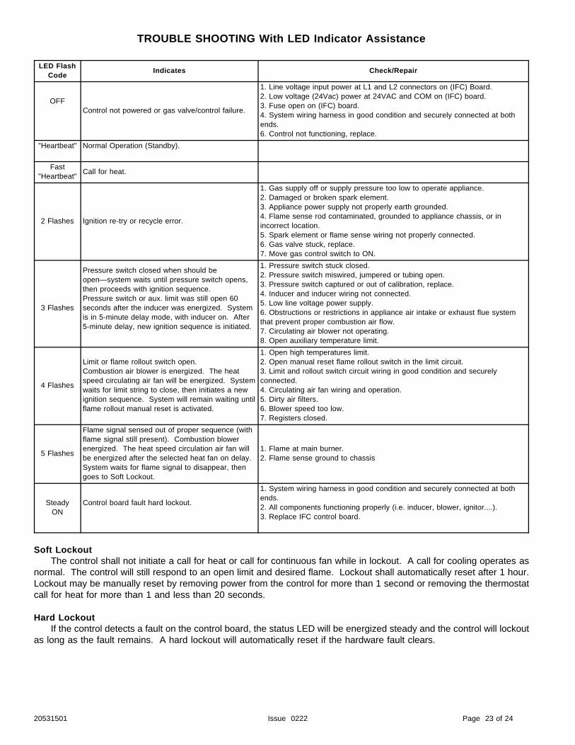
TROUBLE SHOOTING With LED Indicator Assistance
LED FlashCode
Indicates Check/Repair
OFFControl not powered or gas valve/control failure.
1. Line voltage input power at L1 and L2 connectors on (IFC) Board.2. Low voltage (24Vac) power at 24VAC and COM on (IFC) board.3. Fuse open on (IFC) board.4. System wiring harness in good condition and securely connected at bothends.6. Control not functioning, replace.
"Heartbeat" Normal Operation (Standby).
Fast"Heartbeat"
Call for heat.
2 Flashes Ignition re-try or recycle error.
1. Gas supply off or supply pressure too low to operate appliance.2. Damaged or broken spark element.3. Appliance power supply not properly earth grounded.4. Flame sense rod contaminated, grounded to appliance chassis, or inincorrect location.5. Spark element or flame sense wiring not properly connected.6. Gas valve stuck, replace.7. Move gas control switch to ON.
3 Flashes
Pressure switch closed when should beopen—system waits until pressure switch opens,then proceeds with ignition sequence.Pressure switch or aux. limit was still open 60seconds after the inducer was energized. Systemis in 5-minute delay mode, with inducer on. After5-minute delay, new ignition sequence is initiated.
1. Pressure switch stuck closed.2. Pressure switch miswired, jumpered or tubing open.3. Pressure switch captured or out of calibration, replace.4. Inducer and inducer wiring not connected.5. Low line voltage power supply.6. Obstructions or restrictions in appliance air intake or exhaust flue systemthat prevent proper combustion air flow.7. Circulating air blower not operating.8. Open auxiliary temperature limit.
4 Flashes
Limit or flame rollout switch open.Combustion air blower is energized. The heatspeed circulating air fan will be energized. Systemwaits for limit string to close, then initiates a newignition sequence. System will remain waiting untilflame rollout manual reset is activated.
1. Open high temperatures limit.2. Open manual reset flame rollout switch in the limit circuit.3. Limit and rollout switch circuit wiring in good condition and securelyconnected.4. Circulating air fan wiring and operation.5. Dirty air filters.6. Blower speed too low.7. Registers closed.
5 Flashes
Flame signal sensed out of proper sequence (withflame signal still present). Combustion blowerenergized. The heat speed circulation air fan willbe energized after the selected heat fan on delay. System waits for flame signal to disappear, thengoes to Soft Lockout.
1. Flame at main burner.2. Flame sense ground to chassis
SteadyON
Control board fault hard lockout.
1. System wiring harness in good condition and securely connected at bothends.2. All components functioning properly (i.e. inducer, blower, ignitor....).3. Replace IFC control board.
Soft LockoutThe control shall not initiate a call for heat or call for continuous fan while in lockout. A call for cooling operates as
normal. The control will still respond to an open limit and desired flame. Lockout shall automatically reset after 1 hour.Lockout may be manually reset by removing power from the control for more than 1 second or removing the thermostatcall for heat for more than 1 and less than 20 seconds.
Hard LockoutIf the control detects a fault on the control board, the status LED will be energized steady and the control will lockout
as long as the fault remains. A hard lockout will automatically reset if the hardware fault clears.
20531501 Issue 0222 Page 23 of 24

WIRING DIAGRAM
20531501 Issue 0222 Page 24 of 24