Embed Size (px)
Citation preview

ServicingInstructionsType C BoilersG.C.N: 41-116-06
41-116-07LEAVE THESE INSTRUCTIONSWITH THE END-USER
Country of destination: GB

2
1. SERVICING INSTRUCTIONS
1.1 REPLACEMENT OF PARTS
1.2 TO GAIN GENERAL ACCESS
- Removing the front panel- Removing the sealed chamber front cover- Removing the side panels
1.3 ACCESS TO THE COMBUSTION CHAMBER
- Removing the combustion cover- Removing the burner and jets- Removing the electrodes- Removing the main heat exchanger- Removing the air pressure switch- Removing the fan
1.4 SERVICING AND REMOVAL OF THE GAS VALVE
- Setting the gas pressures- Removing the spark generator- Removing the gas valve
1.5 ACCESS TO THE WATER CIRCUIT
- Removing the pump pressure switch- Removing the safety valve- Removing the automatic air vent- Removing the pump- Removing the pressure gauge- Removing the expansion vessel- Removing the overheat thermostat- Removing the frost thermostat- Removing the regulation thermostat
1.6 ACCESS TO THE CONTROL SYSTEM
- Checking the fuses- Removing the P.C.B.s
2. FAULT FINDING
2.1 FAULT FINDING GUIDE (FLOW-CHARTS)
3. ELECTRICAL DIAGRAMS
4. SHORT SPARE PARTS LIST
TABLE OF CONTENTS

2. The control panel moves downward and when pulled forward,rotates on two lateral hinges; the panel stays in a semi-horizontal position, which allows access to the inner parts ofthe boiler (FIG. 1.2);
3. In order to increase the manouvering space, it is possible toraise the control panel and rotate it to a fully horizontal position(FIG. 1.3);
4. Remove the screws “B” from the front panel bottom lip (FIG. 1.4);
5. Lift the front panel up and forward from the raised screws at thethe top of the casing (FIG. 1.5).
FIG. 1.4
B
FIG. 1.5
3
1. SERVICING INSTRUCTIONS
The life of individual components varies and they will needservicing or replacing as and when faults develop.The fault finding sequence chart in chapter 2 will help to locatewhich component is the cause of any malfunction, and instructionsfor removal, inspection and replacement of the individual parts aregiven in the following pages.
1.1 REPLACEMENT OF PARTS
1.2 TO GAIN GENERAL ACCESS
All testing and maintenance operations on the boiler require thecontrol panel to be lowered. This will also require the removal ofthe casing.
1.2.1 Removing the front panel
1. Loosen the fastening screws “A” of the control panel located onthe lower part of the panel itself. (FIG. 1.1);
A
FIG. 1.3
FIG. 1.1
FIG. 1.2
To ensure efficient safe operation, it is recommended that theboiler is serviced annually by a competent person.
Before starting any servicing work, ensure both the gas andelectrical supplies to the boiler are isolated and the boiler iscool.Before and after servicing, a combustion analysis should be madevia the flue sampling point (please refer to the Installation Manualfor further details).
After servicing, preliminary electrical system checks must becarried out to ensure electrical safety (i.e. polarity, earth continuity,resistance to earth and short circuit).

4
1.2.2 Removing the sealed chamber front cover
1. Remove the screws “C” (FIG. 1.6);2. Lift the sealed chamber front cover from the locating pins
(FIG. 1.7).
FIG. 1.6
CC
FIG. 1.7
1.2.3 Removing the side panels
1. Remove the four screws “D” for each side panel (FIG.1.8);2. Pull the panel away from the boiler at the base, then lift the
panel up and remove from the boiler.
D
D
D
FIG. 1.8
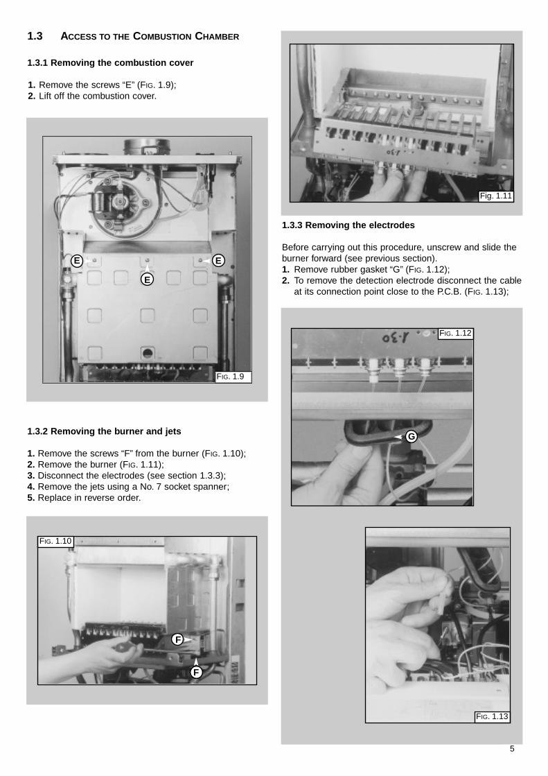
1.3.3 Removing the electrodes
Before carrying out this procedure, unscrew and slide theburner forward (see previous section).1. Remove rubber gasket “G” (FIG. 1.12);2. To remove the detection electrode disconnect the cable
at its connection point close to the P.C.B. (FIG. 1.13);
FIG. 1.12
G
FIG. 1.13
1.3.2 Removing the burner and jets
1. Remove the screws “F” from the burner (FIG. 1.10);2. Remove the burner (FIG. 1.11);3. Disconnect the electrodes (see section 1.3.3);4. Remove the jets using a No. 7 socket spanner;5. Replace in reverse order.
5
1.3.1 Removing the combustion cover
1. Remove the screws “E” (FIG. 1.9);2. Lift off the combustion cover.
1.3 ACCESS TO THE COMBUSTION CHAMBER
E
E
E
FIG. 1.9
FIG. 1.10
Fig. 1.11
F
F

6
3. Remove screw “H” (FIG. 1.14);4. Gently slide the electrode downward (FIG. 1.15).
To replace, repeat the steps in reverse order, payingparticular attention to the following:a -Centre the electrode in the positioning hole carefully,
otherwise the electrode may break;b -Ensure that the left hand and right hand electrodes are
located the correct way round (facing each other), togive the correct spark gap;
c -Check that the cables have been connected correctly;d -Check that the rubber gasket covers the cable/ electrode
connection point completely.
FIG. 1.14
FIG. 1.15
H
1. Drain the boiler of water;2. Release the overheat thermostat sensor “I” (FIG. 1.16);3. Release the two connection nuts “J” connecting the
exchanger to the flow and return pipes (FIG. 1.17);4. Remove the heat exchanger by sliding forward (FIG.
1.18).
1.3.4 Removing the main heat exchanger
FIG. 1.17
J
Fig. 1.16
I
FIG. 1.18

1. Disconnect electrical connections “N” and silicon pipe “O”(FIG.1.22);
2. Remove screw “P” and remove the fan collar clamp “Q”(FIG.1.23);
3. Remove screws “R” (FIG.1.24);4. Remove fan and mounting plate (FIG.1.25).
1.3.6 Removing the fan
1. Disconnect the electrical connections “K” and siliconepipes “L” from their connection points (FIG. 1.19);
2. Remove screws “M” on the top of the sealed chamber(FIG. 1.20);
3. Lift out the air pressure switch (FIG. 1.21);4. Unscrew to remove the switch from the plate.
FIG. 1.20
FIG. 1.19
7
1.3.5 Removing the air pressure switch
L
L
K
M
M
FIG. 1.21
FIG. 1.24
R
R
FIG. 1.23
PQ
FIG. 1.22
N
O
FIG. 1.25

8
1.4 SERVICING AND REMOVAL
OF THE GAS VALVE
1.4.1 Setting the gas pressures
1
2
3
4
A
B
C
F
G
D
Setting the minimum and the maximum power of the boiler1. Check that the supply pressure to the gas valve is a minimum of 20 mbar
for natural gas. Turn off the gas supply at the isolation point under theboiler
2. To do this, slacken the screw “A”.Fit the pipe of the pressure gauge to the inlet pressure test point of the gasvalve “B”.Turn on the gas supply at the isolation point under the boiler and withthe boiler running, read the inlet working pressure on the gauge.When you have completed this operation, turn off the gas supply at theisolation point under the boiler, remove the pressure gauge and tightenthe screw “A” securely into its housing to seal off the gas. Turn on the gassupply at the isolation point under the boiler and test the screw forgas escaping with an approved soap and water solution.
3. To check the pressure supplied by the gas valve to the burner, with theboiler turned off, slacken the screw “C”. Fit the pipe of the pressure gaugeto the outlet pressure test point of the gas valve “D”.Disconnect the compensation pipe “E”either from the gas valve or fromthe sealed chamber.
4. Push the On/Off button to “ON” position -green light- and push the Heatingbutton to “ON” position -green light-Turn on the boiler by setting the external controls.Adjust the 10mm nut “F” on the modureg to set the gas pressure Turn thenut clockwise to increase and anti clockwise to decrease the pressure untilthe required pressure is achieved (see TABLE A page 9)
5. To set the minimum power, disconnect the supply cable from the moduregand adjust screw “G” whilst holding nut “F”.Turn the screw clockwise to increase the pressure and anticlockwise todecrease the pressure until the required pressure is achieved (see TABLE
A page 9)6. When you have completed the above operations, turn off the external
controls, re-connect the supply terminal to the modureg on the gas valveand replace the cap on the screw of the modureg.
Setting pressure for soft ignition.The soft light pressure is factory set.If the ignition is not regular (e.g: not complete burner ignition or ignitionnoise) check the soft light regulator position.The soft light pressure will need adjusting as follows:- Turn off electrical supply;- referring to diagram 5, open the dust cap of the soft light regulator, by
unscrewing in clockwise direction the white screw;- turn the adjustment screw one step in the direction max to increase or in
the direction min to decrease the soft light pressure;- after each adjustment of the regulator, turn on the electrical supply and
recheck burner ignition (wait 20 seconds between each cycle to allow the gas valves’ internal servo system to reset). When the required level is achieved, close the dust cap.
7. Remove the pipe from the pressure gauge and connect screw “C” to thepressure outlet in order to seal off the gas.
8. Carefully check the pressure outlets for gas leaks (valve inlet and outlet).
IMPORTANT!Whenever you disassembleand reassemble the gasconnections, always check forleaks using an approved soapand water solution.
VG002Ac
VG002Ad
VG002Af
VG002Ae
E
VG
002A
b5

9
GA
S B
UR
NE
R P
RE
SS
UR
E
OPERATING POWER
Regulating the heating power fornatural gas (G20)
GA
S B
UR
NE
R P
RE
SS
UR
E
OPERATING POWER
Regulating the heating power forbutane gas (G30)
GA
S B
UR
NE
R P
RE
SS
UR
E
OPERATING POWER
Regulating the heating power forpropane gas (G31)
21 R
FF
I28
RF
FI
2.4
20
8.5 3.3
0.71.7
1.05
3.15
1.26
11
1.6
84.7
111.1
1.78 1.7662.8 62.1
27.5 27.2
14.6
3.1
37.4
0.78 0.77
27.5
6.2 2.4 8.0
10.7
37.0
44.5
2.34
0.94
82.6
33.2
2.31
0.93
81.5
32.8
4.3
0.6
27.7
4.6
10.8
1.8
35.5
6.0
13.8
2.3
14 x 1.30 14 x 0.77 14 x 0.77
TABLE A
21 kW
28 kW
21 kW
28 kW
21 kW
28 kW
CG004A
CG005A
CG006A
TB
005A

10
FIG. 1.28
FIG. 1.29
FIG. 1.30
U
VV
1.4.3 Removing the gas valve
Important! Before removing the gas valve, ensure the gassupply is turned off.
1. Disconnect all the cables from the solenoid andmodureg;
2. Remove the spark generator (see previous section);3. Release the top nut “U” (FIG. 1.28);4. Remove the screws “V” from the bottom of the gas valve
pipe (FIG. 1.29);5. Remove the gas valve (FIG. 1.30).
1.4.2 Removing the spark generator
1. Disconnect ignition leads “S” by pulling upward(FIG. 1.26);
2. Remove the screw “T” (FIG. 1.27);3. Remove the spark generator by pulling forward from the
gas valve.
FIG. 1.27
FIG. 1.26
S
T

11
1. 5. 2 Removing the safety valve
1. Loosen nut “Y” (FIG. 1.33);2. Disconnect the discharge pipe work from below the
boiler;3. Unscrew and remove the valve.
1.5.3 Removing the automatic air vent1. Unscrew valve top “Z” (FIG. 1.34);2. Remove valve complete with float (FIG 1.35).
FIG. 1.33
FIG. 1.34
Y
Z
FIG. 1.35
Important! Before any component is removed, the boilermust be drained of all water.
1.5 ACCESS TO THE WATER CIRCUIT
FIG. 1.31
W
FIG. 1.32
X
1.5.1 Removing the pump pressure switch
1. Remove the cable of the pump pressure switch “W”(Fig. 1.31);
2. Unscrew the pump pressure switch by using a spanneron the nut “X”(FIG. 1.32);
3. Remove the pump pressure switch.
12
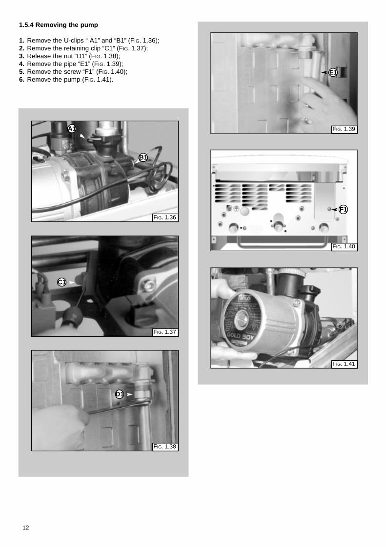
1.5.4 Removing the pump
1. Remove the U-clips “ A1” and “B1” (FIG. 1.36);2. Remove the retaining clip “C1” (FIG. 1.37);3. Release the nut “D1” (FIG. 1.38);4. Remove the pipe “E1” (FIG. 1.39);5. Remove the screw “F1” (FIG. 1.40);6. Remove the pump (FIG. 1.41).
FIG. 1.37
FIG. 1.36
FIG. 1.38
C1
A1
B1
FIG. 1.39
FIG. 1.40
FIG. 1.41
D1
E1
F1

13
1.5.6 Removing the expansion vessel
1. Release nuts “H1” and remove the gas pipe (FIG. 1.44);2. Release nut “I1” (FIG. 1.45);3. Remove lock-nut “J1” (FIG. 1.46);4. Remove the expansion vessel (FIG. 1.47).
1.5.5 Removing the pressure gauge
1. Remove the U-clip “G1” and remove the pressure gaugecoupling (FIG. 1.42);
2. Push the pressure gauge through the control panel fromthe rear (FIG. 1.43).
FIG. 1.42FIG. 1.44
G1
FIG. 1.43
H1
I1
FIG. 1.45
FIG. 1.46
FIG. 1.47
H1
J1

14
1.5.6 Removing the overheat thermostat
1. Disconnect the overheat thermostat electricalconnections “K1” (FIG. 1.48);
2. Then remove the thermostat from its mounting byreleasing the securing clip (FIG. 1.49).
1.5.7 Removing the frost thermostat
1. Disconnect the frost thermostat electrical connection“L1” (FIG. 1.50);
2. Then remove the thermostat from its mounting byreleasing the securing clip (FIG. 1.51).
1.5.8 Removing the regulation thermostat
1. Remove the regulation thermostat sensor from itsmounting by releasing the securing clip “M1” (FIG. 1.52);
2. Separate the facia panel from the rear of the controlpanel (see section 1.6.2);
3. Remove the electrical connections “N1 from theregulation thermostat (FIG. 1.53);
4. Pull the regulation knob from the spindle of thethermostat;
5. Remove the thermostat from the control panel facia byunscrewing the mounting screws.
FIG. 1.48
FIG. 1.49
K1
FIG. 1.52
FIG. 1.51
M1
L1
FIG. 1.50FIG. 1.53
N1

15
1.6.2 Removing the P.C.B.s
1. Isolate electricity;2. Remove the screws “O1” (FIG. 1.56);3. Separate the facia panel from the rear of the control
panel;4. Unplug all electrical connections from the P.C.B. and
remove the screws “P1” and remove the P.C.B. (FIG.1.57).
FIG. 1.56
O1
O1 O1
O1O1
P1
P1
P1P1
O1
FIG. 1.57
1.6.1 Checking the fuse
1. Remove the inspection cover on the reverse of thecontrol panel (FIG. 1.54);
2. Remove the fuse mounted on the reverse of theinspection cover (FIG. 1.55).
1.6 ACCESS TO THE CONTROL SYSTEM
FIG. 1.54
FIG. 1.55
Important! Isolate the electrical supply to the boiler beforeaccessing the control panel.

16 B063
2. FAULT FINDING
PRELIMINARY CHECKSMAKE SURE THAT:
ISTHE SUPPLY
L.E.D. ILLUMINATED?
ISTHE L.E.D.
ILLUMINATED?
NO
NO
NO
YES
NO
1 - CHECK THE FUSES2 - CHECK THERE IS POWER
SUPPLIED TO THE P.C.B.S3 - CHECK/REPLACE THE P.C.B.
(CT1)
1 - CHECK THE INTEGRITYOF THE L.E.D.
2 - CHECK/REPLACE THE P.C.B.(CT1)
PRESS THEON/OFF BUTTON
PRESS THE CENTRALHEATING BUTTON
FROSTPROTECTION IS
ACTIVATED <5¡C. IS THEFROSTPROTECTION
REQUESTED?
ISTIME CLOCK/
PROGRAMMERAND/OR ROOM
CALLING FORHEATING?
THE
THERMOSTAT
A
1 - THERE IS SUFFICIENTWATER IN THE SYSTEM
2 - THE GAS IS TURNED ON3 - THE ELECTRICAL SUPPLY
IS TURNED ON
YES
YES
YES
It is possible to detect and correct any defect by using the standard faultfinding diagrams described in this chapter.
2.1 FAULT FINDING GUIDE
(FLOW-CHARTS)
FC
002A
a

17B063
IS THE PUMPRUNNING? NO
YES
POWER TOTHE PUMP?
1 - CHECK THE OPERATIONOF THE PUMP
2 - RELEASE/REPLACE THEPUMP
1 - CHECK THE PUMP CABLE2 - CHECK/REPLACE P.C.B.
(CT1)3 - CHECK THE SYSTEM
PRESSURE GAUGE IS AT1.5 BAR
A
IS THE FANRUNNING?
BOILERSHUTDOWN?
POWER TOTHE FAN?
NO
YES
YES
NO
YES
NO
NO
YES
1 - CHECK/REPLACE AIRPRESSURE SWITCHAND CABLE
2 - CHECK IF THE RESET
DETECTION ELECTRODE
IS JAMMED3 - CHECK/REPLACE
1 - CHECK/REPLACE FANCONNECTION CABLE
2 - CHECK/REPLACE P.C.B.3 - CHECK/REPLACE AIR
PRESSURE SWITCH
1 - REPLACE THE FAN
1 - RESET THE BOILER
INTERNALP.C.B. PROTECTION
ACTIVATED?
B
NO
YES
FC
002A
b

18 B063
IS THE BURNERALIGHT?
YES
NO
YES
YES
BOILERWORKING?
YES
NO
NO
NO
NO
YES
5 - CHECK/REPLACE P.C.B. (CBM2)
4 - CHECK/REPLACE P.C.B. (CBM2)
4 - CHECK/REPLACEP.C.B. (CBM2)
1 - CHECK/REPLACE IGNITIONELECTRODES
2 - CHECK THE CABLES3 - CHECK SPARK GENERATOR4 - CHECK IGNITION ELECTRODE
CABLES
1 - CHECK POWER SUPPLY TOTHE GAS VALVE
2 - CHECK OPERATION OF THEGAS VALVE
3 - REPLACE THE GAS VALVE
1 - CHECK IF THE FLAME
ELECTRODE2 - CHECK THE SOFT-LIGHT
GAS PRESSURE3 - CHECK/REPLACE DETECTION
ELECTRODE
STRIKES THE DETECTION
PRESS THE RESETBUTTON
IS THEAIR PRESSURE SWITCH
ACTIVATED?
CHECKP ON PRESSURE
TEST POINT
DOESTHE SPARKSEQUENCE
START?
HAS THEBOILER SAFETY
SHUTDOWN BEENACTIVATED?
1 - CHECK EXHAUST DISCHARGE2 - CHECK VENTURI AND TUBES3 - CHECK THE FAN EFFICIENCY4 - REPLACE FAN
1 - CHECK AIR PRESSURESWITCH CABLE
2 - CHECK/REPLACE AIRPRESSURE SWITCH
3 - CHECK/REPLACE P.C.B.(CBM2)
B
P mbar0.5
P 0.5 mbar∆
ISTHERE STILLA PROBLEM?
NORMALOPERATION
NORMALOPERATION
NOYES
FAULT LIST POSSIBLE CAUSES1
2
3
4
5
NOISEY OPERATIONNOISEY OPERATION
DECREASE/INCREASE OF HEATING CIRCUITPRESSUREDECREASE/INCREASE OF HEATING CIRCUITPRESSURE
REPEATED SHUTDOWNSREPEATED SHUTDOWNS
REPEATED OPERATION OF SAFETY THERMOSTATREPEATED OPERATION OF SAFETY THERMOSTAT
INSUFFICIENT RADIATOR TEMPERATUREINSUFFICIENT RADIATOR TEMPERATURE
- MAIN HEAT EXCHANGER FAULTY OR BLOCKEDWITH LIME-SCALE DEPOSITS
- LOW HEATING SYSTEM WATER PRESSURE- CHECK GAS PRESSURES- CHECK HEATING THERMOSTAT- CHECK FAN- CHECK PUMP
- MAIN HEAT EXCHANGER FAULTY OR BLOCKEDWITH LIME-SCALE DEPOSITS
- LOW HEATING SYSTEM WATER PRESSURE- CHECK GAS PRESSURES- CHECK HEATING THERMOSTAT- CHECK FAN- CHECK PUMP
- CHECK FOR LEAKS ON THE HEATING CIRCUIT- FAULTY FILLING LOOP- FAULTY EXPANSION VESSEL
- CHECK FOR LEAKS ON THE HEATING CIRCUIT- FAULTY FILLING LOOP- FAULTY EXPANSION VESSEL
- FAULTY DETECTION ELECTRODES- CHECK GAS PRESSURES- CHECK FLAME DETECTION ELECTRICAL CIRCUIT
- FAULTY DETECTION ELECTRODES- CHECK GAS PRESSURES- CHECK FLAME DETECTION ELECTRICAL CIRCUIT
- FAULTY HEATING THERMOSTAT- FAULTY OVERHEAT THERMOSTAT- PRESENCE OF AIR IN THE HEATING CIRCUIT- CHECK BURNER PRESSURES- CHECK EXCHANGER FLUEWAY
- FAULTY HEATING THERMOSTAT- FAULTY OVERHEAT THERMOSTAT- PRESENCE OF AIR IN THE HEATING CIRCUIT- CHECK BURNER PRESSURES- CHECK EXCHANGER FLUEWAY
- CHECK HEATING THERMOSTAT- CHECK BY-PASS- CHECK GAS PRESSURE
- CHECK HEATING THERMOSTAT- CHECK BY-PASS- CHECK GAS PRESSURE
∆
≤
∆
FC
002A
c

19B063
3. ELECTRICAL
DIAGRAMS
SE011A
LEGEND:
A - On/Off SwitchB - On/Off L.E.D.C - Heating SwitchD - Heating L.E.D.E - Reset ButtonF - Ignition Failure (Lockout) L.E.D.
A01 - Pump Pressure SwitchA02 - Frost ThermostatA03 - ModulatorA04 - Circulation PumpA05 - Regulation Thermostat
A06 - External Control SystemA07 - Time Clock ConnectorA08 - External (Room) ThermostatA09 - Air Pressure SwitchA10 - FanA11 - Overheat ThermostatA12 - Spark Generator/Gas Valve SupplyA13 - Detection Electrode
Colours:Wh -WhiteBl -BlueGry -GreyBrn -BrownBlk -BlackRd -RedGrn/Yll -Yellow/Green

20 B063
SF008A

21B063
21/28 RFFI354
353
352351
33
63 61
9
10
11
12
7
4
3
2
60
62
1
1112
11 1165676869 64
11
72
104
100
9799
98
77
79
8081
101
80
106107 105
10375
76 102
13
64
66
1164 64
82
59
89
74
1324 30 31 32 37 38
13
19
20
16
14
17
15
58
57
56
5554
53
49
41 43
47
48
4645
44
50
42
13
94
21 2322
19
301 302 303
304
38 3839
9347
29
85
515296
95
92
4036 3733 34 35
90
18
84
86
13
28272625
6
83
8788
8
5
31
78
73
71 70
91
4. SHORT SPARE
PARTS LIST
microSYSTEM 21/28 RFFI
ES
002A

22 B063
998616573521573520570760998612573528998447569390998627999542574279999475998809999476998424998836999091999577999499999245998517998484571651997182998943998489999894998620998893999538998618998669998887998939998433998434999501950030998623998622998624998644998643998738998961999207998716998717
Keyno.
G.C. partno.
ARISTONPart No.Description
25
13161819212223252627293031
33AB33CD
45484955
60AB60CD
7375
76AB76CD78AB78CD
8183A83B83C83D
87AC87BD
9395979899
351352353
354AB354CD
361362
164 282164 225
164 229
164 261
E03 818
E24 076E24 075
Expansion vesselGasket 3/8"Gasket 3/4"Thermostat (frost)Flow groupGasket 1/2"Safety valve (1/4" 3 bar)Gasket 1/4"Pump pressure switchSpark GeneratorGasketGas valveAuto air ventReturn groupO-ringPumpPumpThermostat (regulation)P.C.B. (CBM2 AT-FFI2X)Pressure gaugeGasketAir pressure switchAir pressure switchGasketO-ring (2.65 x 10.27)FanFanMain exchangerMain exchangerThermostat (overheat)Burner 12 ramp (natural gas)Burner 12 ramp (LPG)Burner 14 ramp (natural gas)Burner 14 ramp (LPG)Burner jet (natural gas 1.30)Burner jet (LPG 0.77)P.C.B. (CT1)Fast fuse 2ATElectrode (ignition R.H.)Electrode (ignition L.H.)Detection electrodeO-ring (A.A.V.)Auto air ventGasket (pump head)Pump headPump headBurner jet 1.30 full kit (natural gas)Burner jet 0.77 full kit (LPG)
1
1111
1111111111111
11
1
1111
111111111111
microSYSTEM 21/28 RFFI

23B063
NOTES

23 9
9 84
155
0 00
0 -
Manufacturer: Merloni TermoSanitari SpA - Italy
Commercial subsidiary: MTS (GB) LIMITEDMTS BuildingHughenden AvenueHigh WycombeBucks HP13 5FT
Telephone: (01494) 755600
Fax: (01494) 459775
Internet: http://www.mtsgb.ltd.uk
E-mail: [email protected]
Technical Service Hot Line: (01494) 539579


![Excell 80sp Installation and Servicing Instructions[1]](https://img.pdfslide.net/doc/110x75/5520bdd84979590a3f8b4b4c/excell-80sp-installation-and-servicing-instructions1.jpg)